
Basic Arithmetic
4.1 Introduction
At this point, algorithms for initialization, clearing, zeroing, copying, comparing, and setting small constants have been established. The next logical set of algorithms to develop are addition, subtraction, and digit shifting algorithms. These algorithms make use of the lower level algorithms and are the crucial building block for the multiplication algorithms. It is very important that these algorithms are highly optimized. On their own they are simple O(n) algorithms but they can be called from higher level algorithms, which easily places them at O(n2) or even O(n3) work levels.
All of the algorithms within this chapter make use of the logical bit shift operations denoted by ![]() and
and ![]() for left and right logical shifts, respectively. A logical shift is analogous to sliding the decimal point of radix-10 representations. For example, the real number 0.9345 is equivalent to 93.45%, which is found by sliding the decimal two places to the right (multiplying by β2 = 102). Algebraically, a binary logical shift is equivalent to a division or multiplication by a power of two. For example, a
for left and right logical shifts, respectively. A logical shift is analogous to sliding the decimal point of radix-10 representations. For example, the real number 0.9345 is equivalent to 93.45%, which is found by sliding the decimal two places to the right (multiplying by β2 = 102). Algebraically, a binary logical shift is equivalent to a division or multiplication by a power of two. For example, a ![]() k= a· 2k while
k= a· 2k while ![]() .
.
One significant difference between a logical shift and the way decimals are shifted is that digits below the zero′th position are removed from the number. For example, consider 11012 ![]() 1; using decimal notation this would produce 110.12. However, with a logical shift the result is 1102.
1; using decimal notation this would produce 110.12. However, with a logical shift the result is 1102.
4.2 Addition and Subtraction
In common twos complement fixed precision arithmetic negative numbers are easily represented by subtraction from the modulus. For example, with 32-bit integers, a – b(mod 232) is the same as a+(232– b) (mod 232) since 232 = 0 (mod 232). As a result, subtraction can be performed with a trivial series of logical operations and an addition.
However, in multiple precision arithmetic, negative numbers are not represented in the same way. Instead, a sign flag is used to keep track of the sign of the integer. As a result, signed addition and subtraction are actually implemented as conditional usage of lower level addition or subtraction algorithms with the sign fixed up appropriately.
The lower level algorithms will add or subtract integers without regard to the sign flag. That is, they will add or subtract the magnitude of the integers, respectively.
4.2.1 Low Level Addition
An unsigned addition of multiple precision integers is performed with the same long-hand algorithm used to add decimal numbers; that is, to add the trailing digits first and propagate the resulting carry upward. Since this is a lower level algorithm, the name will have a “s_” prefix. Historically, that convention stems from the MPI library, where “s_” stood for static functions that were hidden from the developer entirely.
Algorithm s_mp_add. This algorithm is loosely based on algorithm 14.7 of HAC [2, pp. 594], but has been extended to allow the inputs to have different magnitudes. Coincidentally, the description of algorithm A in Knuth [1, pp. 266] shares the same deficiency as the algorithm from [4]. Even the MIX pseudo machine code presented by Knuth [1, pp. 266–267] is incapable of handling inputs of different magnitudes (Figure 4.1).
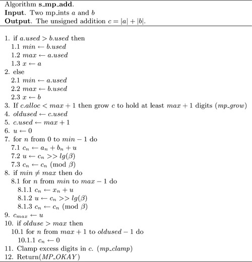
The first thing that has to be accomplished is to sort out which of the two inputs is the largest. The addition logic will simply add all of the smallest input to the largest input and store that first part of the result in the destination. Then, it will apply a simpler addition loop to excess digits of the larger input.
The first two steps will handle sorting the inputs such that min and max hold the digit counts of the two inputs. The variable x will be an mp_int alias for the largest input or the second input b if they have the same number of digits. After the inputs are sorted, the destination c is grown as required to accommodate the sum of the two inputs. The original used count of c is copied and set to the new used count.
At this point, the first addition loop will go through as many digit positions as both inputs have. The carry variable μ is set to zero outside the loop. Inside the loop an “addition” step requires three statements to produce one digit of the summand. The first two digits from a and b are added together along with the carry μ. The carry of this step is extracted and stored in μ, and finally the digit of the result cn is truncated within the range 0 ≤ cn<β.
Now all of the digit positions that both inputs have in common have been exhausted. If min ≠ max, then x is an alias for one of the inputs that has more digits. A simplified addition loop is then used to essentially copy the remaining digits and the carry to the destination.
The final carry is stored in cmax, and digits above max up to oldused are zeroed, which completes the addition.
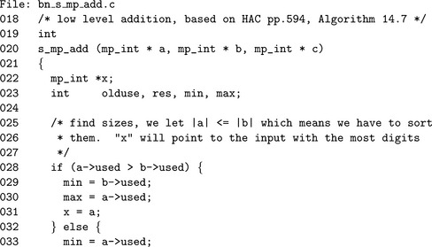

We first sort (lines 28 to 36) the inputs based on magnitude and determine the min and max variables. Note that x is a pointer to an mp_int assigned to the largest input, in effect it is a local alias. Next, we grow the destination (38 to 42) to ensure it can accommodate the result of the addition.
Similar to the implementation of mp_copy, this function uses the braced code and local aliases coding style. The three aliases on lines 56, 59 and 62 represent the two inputs and destination variables, respectively. These aliases are used to ensure the compiler does not have to dereference a, b, or c (respectively) to access the digits of the respective mp_int.
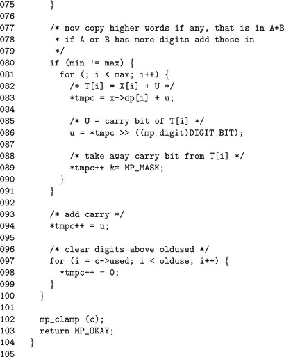
The initial carry u will be cleared (line 65); note that u is of type mp_digit, which ensures type compatibility within the implementation. The initial addition (lines 66 to 75) adds digits from both inputs until the smallest input runs out of digits. Similarly, the conditional addition loop (lines 81 to 90) adds the remaining digits from the larger of the two inputs. The addition is finished with the final carry being stored in tmpc(line 94). Note the “++” operator within the same expression. After line 94, tmpc will point to the c.used′th digit of the mp_int c. This is useful for the next loop (lines 97 to 99), which sets any old upper digits to zero.
4.2.2 Low Level Subtraction
The low level unsigned subtraction algorithm is very similar to the low level unsigned addition algorithm. The principal difference is that the unsigned subtraction algorithm requires the result to be positive. That is, when computing a – b, the condition |a| ≥ |b| must be met for this algorithm to function properly. Keep in mind this low level algorithm is not meant to be used in higher level algorithms directly. This algorithm as will be shown can be used to create functional signed addition and subtraction algorithms.
For this algorithm, a new variable is required to make the description simpler. Recall from section 1.3.1 that a mp_digit must be able to represent the range 0 ≤ x < 2β for the algorithms to work correctly. However, it is allowable that a mp_digit represent a larger range of values. For this algorithm, we will assume that the variable γ represents the number of bits available in a mp_digit (this implies 2γ>β).
For example, the default for LibTomMath is to use a “unsigned long” for the mp_digit “type” while β 228. In ISO C, an “unsigned long” data type must be able to represent 0 = x < 232, meaning that in this case γ ≥ 32.
Algorithm s_mp_sub. This algorithm performs the unsigned subtraction of two mp_int variables under the restriction that the result must be positive. That is, when passing variables a and b the condition that |a| > |b| must be met for the algorithm to function correctly. This algorithm is loosely based on algorithm 14.9 [2, pp. 595] and is similar to algorithm S in [1, pp. 267] as well. As was the case of the algorithm s_mp_add both other references lack discussion concerning various practical details such as when the inputs differ in magnitude (Figure 4.2).
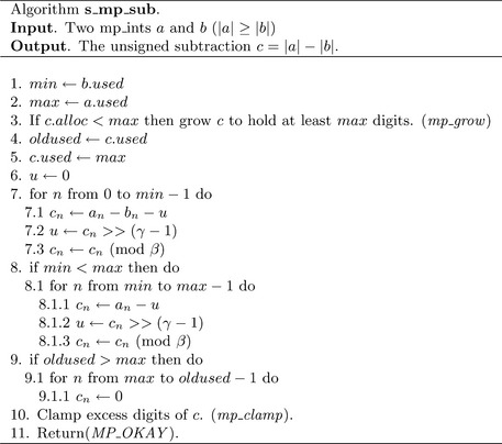
The initial sorting of the inputs is trivial in this algorithm since a is guaranteed to have at least the same magnitude of b. Steps 1 and 2 set the min and max variables. Unlike the addition routine there is guaranteed to be no carry, which means that the result can be at most max digits in length as opposed to max+ 1. Similar to the addition algorithm, the used count of c is copied locally and set tothe maximal count for the operation.
The subtraction loop that begins on step 7 is essentially the same as the addition loop of algorithm s_mp_add, except single precision subtraction is used instead. Note the use of the γ variable to extract the carry (also known as the borrow) within the subtraction loops. Under the assumption that two’s complement single precision arithmetic is used, this will successfully extract the desired carry.
For example, consider subtracting 01012 from 01002, where γ = 4 and β = 2. The least significant bit will force a carry upwards to the third bit, which will be set to zero after the borrow. After the very first bit has been subtracted, 4–1 = 00112 will remain, When the third bit of 01012 is subtracted from the result it will cause another carry. In this case, though, the carry will be forced to propagate all the way to the most significant bit.
Recall that β < 2γ. This means that if a carry does occur just before the lg(β)′th bit it will propagate all the way to the most significant bit. Thus, the high order bits of the mp_digit that are not part of the actual digit will either be all zero, or all one. All that is needed is a single zero or one bit for the carry. Therefore, a single logical shift right by γ −1 positions is sufficient to extract the carry. This method of carry extraction may seem awkward, but the reason for it becomes apparent when the implementation is discussed.
If b has a smaller magnitude than a, then step 9 will force the carry and copy operation to propagate through the larger input a into c. Step 10 will ensure that any leading digits of c above the max′th position are zeroed.
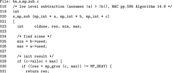
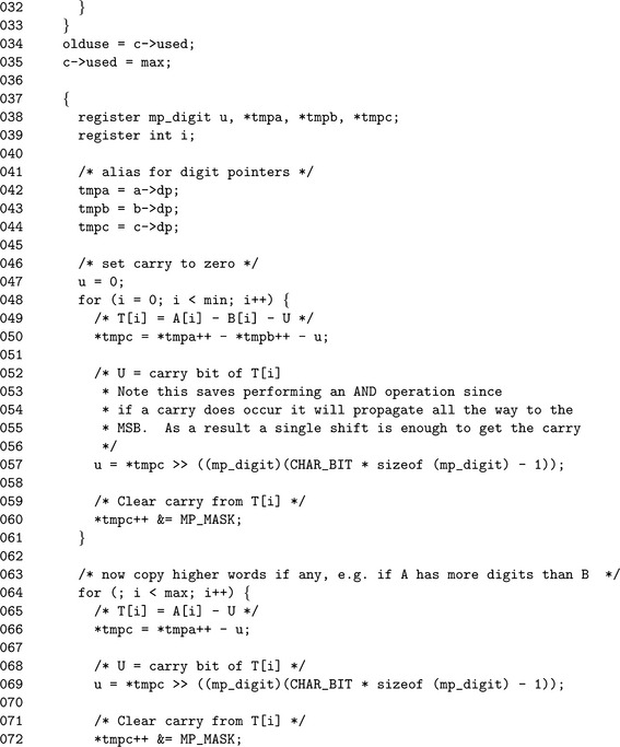
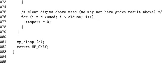
Like low level addition we “sort” the inputs, except in this case, the sorting is hard coded (lines 25 and 26). In reality, the min and max variables are only aliases and are only used to make the source code easier to read. Again, the pointer alias optimization is used within this algorithm. The aliases tmpa, tmpb, and tmpc are initialized (lines 42, 43 and 44) for a, b, and c, respectively.
The first subtraction loop (lines 47 through 61) subtracts digits from both inputs until the smaller of the two has been exhausted. As remarked earlier, there is an implementation reason for using the “awkward” method of extracting the carry (line 57). The traditional method for extracting the carry would be to shift by lg(β) positions and logically AND the least significant bit. The AND operation is required because all of the bits above the lg(β)′th bit will be set to one after a carry occurs from subtraction. This carry extraction requires two relatively cheap operations to extract the carry. The other method is to simply shift the most significant bit to the least significant bit, thus extracting the carry with a single cheap operation. This optimization only works on twos complement machines, which is a safe assumption to make.
If a has a larger magnitude than b, an additional loop (lines 64 through 73) is required to propagate the carry through a and copy the result to c.
4.2.3 High Level Addition
Now that both lower level addition and subtraction algorithms have been established, an effective high level signed addition algorithm can be established. This high level addition algorithm will be what other algorithms and developers will use to perform addition of mp_int data types.
Recall from section 5.2 that an mp_int represents an integer with an unsigned mantissa (the array of digits) and a sign flag. A high level addition is actually performed as a series of eight separate cases that can be optimized down to three unique cases.
Algorithm mp_add. This algorithm performs the signed addition of two mp_int variables. There is no reference algorithm to draw upon from either [4] or [4] since they both only provide unsigned operations. The algorithm is fairly straightforward but restricted, since subtraction can only produce positive results (Figure 4.3).
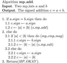
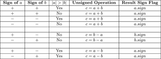
Figure 4.4 lists the eight possible input combinations and is sorted to show that only three specific cases need to be handled. The return code of the unsigned operations at steps 1.2, 2.1.2, and 2.2.2 are forwarded to step 3 to check for errors. This simplifies the description of the algorithm considerably and best follows how the implementation actually was achieved.
Also note how the sign is set before the unsigned addition or subtraction is performed. Recall from the descriptions of algorithms s_mp_add and s_mp_sub that the mp_clamp function is used at the end to trim excess digits. The mp_clamp algorithm will set the sign to MP_ZPOS when the used digit count reaches zero.
For example, consider performing – a + a with algorithm mp_add. By the description of the algorithm the sign is set to MP_NEG, which would produce a result of −0. However, since the sign is set first, then the unsigned addition is performed, the subsequent usage of algorithm mp_clamp within algorithm s_mp_add will force −0 to become 0.
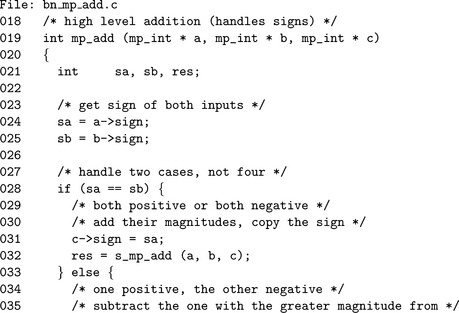
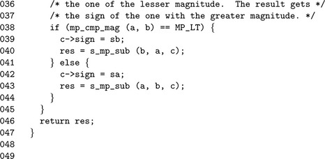
The source code follows the algorithm fairly closely. The most notable new source code addition is the usage of the res integer variable, which is used to pass the result of the unsigned operations forward. Unlike in the algorithm, the variable res is merely returned as is without explicitly checking it and returning the constant MP_OKAY. The observation is this algorithm will succeed or fail only if the lower level functions do so. Returning their return code is sufficient.
4.2.4 High Level Subtraction
The high level signed subtraction algorithm is essentially the same as the high level signed addition algorithm.
Algorithm mp_sub. This algorithm performs the signed subtraction of two inputs (Figure 4.5). Similar to algorithm mp_add there is no reference in either [4] or [4]. Also this algorithm is restricted by algorithm s_mp_sub. Figure 4.6 lists the eight possible inputs and the operations required.
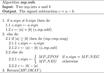
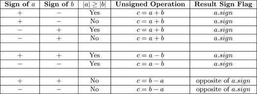
Similar to the case of algorithm mp_add, the sign is set first before the unsigned addition or subtraction, to prevent the algorithm from producing –a – –a= −0 as a result.
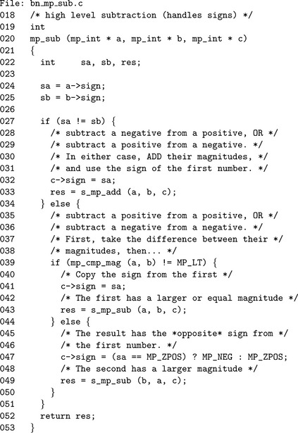
Much like the implementation of algorithm mp_add, the variable res is used to catch the return code of the unsigned addition or subtraction operations and forward it to the end of the function. On line 39, the “not equal to” MP_LT expression is used to emulate a “greater than or equal to” comparison.
4.3 Bit and Digit Shifting
It is quite common to think of a multiple precision integer as a polynomial in x; that is, y= f(β) where f(x) =![]() This notation arises within discussion of Montgomery and Diminished Radix Reduction, and Karatsuba multiplication and squaring.
This notation arises within discussion of Montgomery and Diminished Radix Reduction, and Karatsuba multiplication and squaring.
To facilitate operations on polynomials in x as above, a series of simple “digit” algorithms have to be established. That is to shift the digits left or right and to shift individual bits of the digits left and right. It is important to note that not all “shift” operations are on radix-β digits.
4.3.1 Multiplication by Two
In a binary system where the radix is a power of two, multiplication by two arises often in other algorithms and is a fairly efficient operation to perform. A single precision logical shift left is sufficient to multiply a single digit by two.
Algorithm mp_mul_2. This algorithm will quickly multiply a mp_int by two provided β is a power of two. Neither [4] nor [4] describes such an algorithm despite the fact it arises often in other algorithms. The algorithm is set up much like the lower level algorithm s_mp_add since it is for all intents and purposes equivalent to the operation b= |a| + |a| (Figure 4.7).
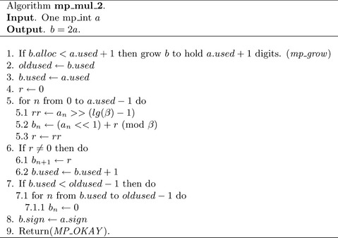
Steps 1 and 2 grow the input as required to accommodate the maximum number of used digits in the result. The initial used count is set to a.used at step 4. Only if there is a final carry will the used count require adjustment.
Step 6 is an optimization implementation of the addition loop for this specific case. That is, since the two values being added together are the same, there is no need to perform two reads from the digits of a. Step 6.1 performs a single precision shift on the current digit an to obtain what will be the carry for the next iteration. Step 6.2 calculates the n′th digit of the result as single precision shift of an plus the previous carry. Recall from Chapter 5 that an ![]() 1 is equivalent to an. 2. An iteration of the addition loop is finished with forwarding the carry to the next iteration.
1 is equivalent to an. 2. An iteration of the addition loop is finished with forwarding the carry to the next iteration.
Step 7 takes care of any final carry by setting the a.used′th digit of the result to the carry and augmenting the used count of b. Step 8 clears any leading digits of b in case it originally had a larger magnitude than a.
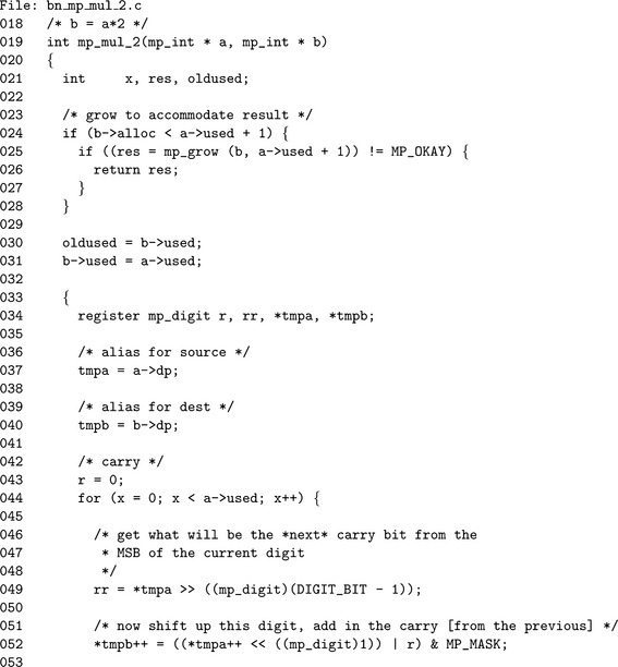
This implementation is essentially an optimized implementation of s_mp_add for the case of doubling an input. The only noteworthy difference is the use of the logical shift operator on line 52 to perform a single precision doubling.
4.3.2 Division by Two
A division by two can just as easily be accomplished with a logical shift right, as multiplication by two can be with a logical shift left.
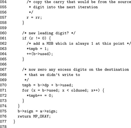
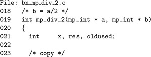
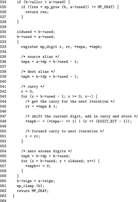
Algorithm mp_div_2. This algorithm will divide an mp_int by two using logical shifts to the right. Like mp_mul_2, it uses a modified low level addition core as the basis of the algorithm. Unlike mp_mul_2, the shift operations work from the leading digit to the trailing digit. The algorithm could be written to work from the trailing digit to the leading digit; however, it would have to stop one short of a.used – 1 digits to prevent reading past the end of the array of digits (Figure 4.8).
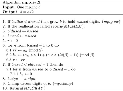
Essentially the loop at step 6 is similar to that of mp_mul_2, except the logical shifts go in the opposite direction and the carry is at the least significant bit, not the most significant bit.
4.4 Polynomial Basis Operations
Recall from section 4.3 that any integer can be represented as a polynomial in x as y = f(β). Such a representation is also known as the polynomial basis [3, pp. 48]. Given such a notation, a multiplication or division by x amounts to shifting whole digits a single place. The need for such operations arises in several other higher level algorithms such as Barrett and Montgomery reduction, integer division, and Karatsuba multiplication.
Converting from an array of digits to polynomial basis is very simple. Consider the integer y = (a2, a1, a0)βand recall that y=![]() . Simply replace βwith x and the expression is in polynomial basis. For example, f(x) = 8 x + 9 is the polynomial basis representation for 89 using radix ten. That is, f(10) = 8(10)+ 9 = 89.
. Simply replace βwith x and the expression is in polynomial basis. For example, f(x) = 8 x + 9 is the polynomial basis representation for 89 using radix ten. That is, f(10) = 8(10)+ 9 = 89.
4.4.1 Multiplication by x
Given a polynomial in x such as f(x) =![]() , multiplying by x amounts to shifting the coefficients up one degree. In this case, f(x) · x =
, multiplying by x amounts to shifting the coefficients up one degree. In this case, f(x) · x =![]() . From a scalar basis point of view, multiplying by x is equivalent to multiplying by the integer β.
. From a scalar basis point of view, multiplying by x is equivalent to multiplying by the integer β.
Algorithm mp_lshd. This algorithm multiplies an mp_int by the b′th power of x. This is equivalent to multiplying by βb. The algorithm differs from the other algorithms presented so far as it performs the operation in place instead of storing the result in a separate location. The motivation behind this change is the way this function is typically used. Algorithms such as mp_add store the result in an optionally different third mp_int because the original inputs are often still required. Algorithm mp_lshd (and similarly algorithm mp_rshd)is typically used on values where the original value is no longer required. The algorithm will return success immediately if b ≤ 0, since the rest of algorithm is only valid when b > 0 (Figure 4.9).
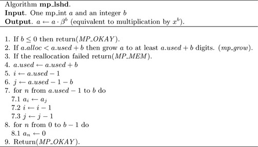
First, the destination a is grown as required to accommodate the result. The counters i and j are used to form a sliding window over the digits of a of length b (Figure 4.10). The head of the sliding window is at i (the leading digit) and the tail at j (the trailing digit). The loop in step 7 copies the digit from the tail to the head. In each iteration, the window is moved down one digit. The last loop in step 8 sets the lower b digits to zero.
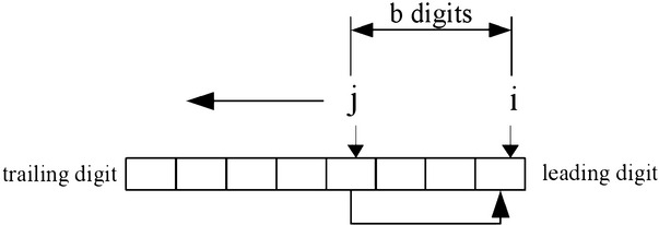

The if statement (line 24) ensures that the b variable is greater than zero since we do not interpret negative shift counts properly. The used count is incremented by b before the copy loop begins. This eliminates the need for an additional variable in the for loop. The variable top(line 42) is an alias for the leading digit, while bottom(line 45) is an alias for the trailing edge. The aliases form a window of exactly b digits over the input.
4.4.2 Division by x
Division by powers of x is easily achieved by shifting the digits right and removing any that will end up to the right of the zero′th digit.
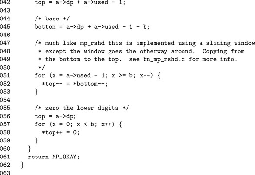
Algorithm mp_rshd. This algorithm divides the input in place by the b′th power of x. It is analogous to dividing by a βb but much quicker since it does not require single precision division. This algorithm does not actually return an error code as it cannot fail (Figure 4.11).
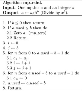
If the input b is less than one, the algorithm quickly returns without performing any work. If the used count is less than or equal to the shift count b then it will simply zero the input and return.
After the trivial cases of inputs have been handled, the sliding window is set up. Much like the case of algorithm mp_lshd, a sliding window that is b digits wide is used to copy the digits. Unlike mp_lshd, the window slides in the opposite direction from the trailing to the leading digit. In addition, the digits are copied from the leading to the trailing edge.
Once the window copy is complete, the upper digits must be zeroed and the used count decremented.
![]()
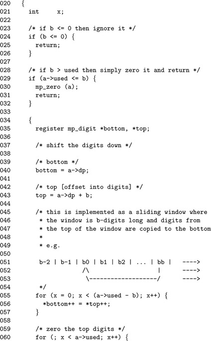
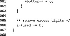
The only noteworthy element of this routine is the lack of a return type since it cannot fail. Like mp_lshd(), we form a sliding window except we copy in the other direction. After the window (line 60), we then zero the upper digits of the input to make sure the result is correct.
4.5 Powers of Two
Now that algorithms for moving single bits and whole digits exist, algorithms for moving the “in between” distances are required. For example, to quickly multiply by 2k for any k without using a full multiplier algorithm would prove useful. Instead of performing single shifts k times to achieve a multiplication by 2±k, a mixture of whole digit shifting and partial digit shifting is employed.
4.5.1 Multiplication by Power of Two
Algorithm mp_mul_2d. This algorithm multiplies a by 2b and stores the result in c. The algorithm uses algorithm mp_lshd and a derivative of algorithm mp_mul_2 to quickly compute the product (Figure 4.12).
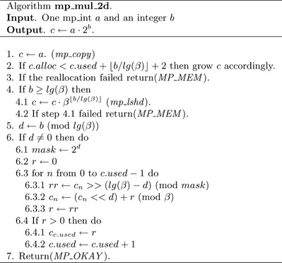
First, the algorithm will multiply a by ![]() , which will ensure that the remainder multiplicand is less than β. For example, if b= 37 and β= 228, then this step will multiply by x leaving a multiplication by 237–28 = 29 left.
, which will ensure that the remainder multiplicand is less than β. For example, if b= 37 and β= 228, then this step will multiply by x leaving a multiplication by 237–28 = 29 left.
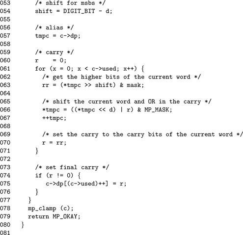
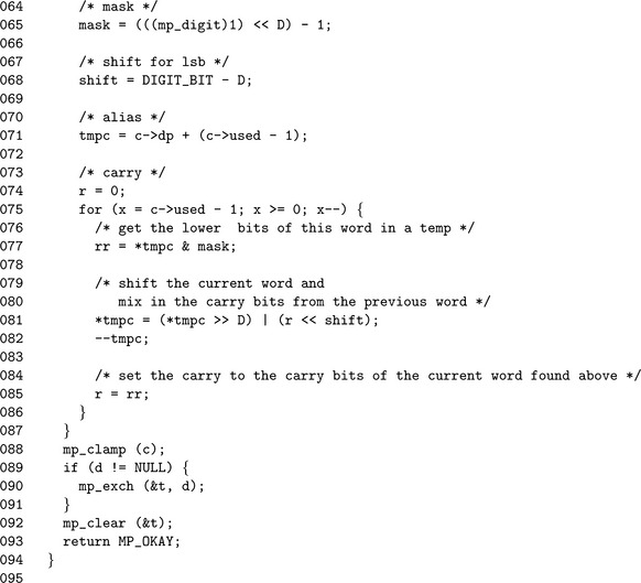
After the digits have been shifted appropriately, at most lg(β) −1 shifts are left to perform. Steps 5 calculates the number of remaining shifts required. If it is non-zero, a modified shift loop is used to calculate the remaining product. Essentially the loop is a generic version of algorithm mp_mul_2 designed to handle any shift count in the range 1 ≤ x < lg(β). The mask variable is used to extract the upper d bits to form the carry for the next iteration.
This algorithm is loosely measured as a O(2n) algorithm, which means that if the input is n-digits, it takes 2n “time” to complete. It is possible to optimize this algorithm down to a O(n) algorithm at a cost of making the algorithm slightly harder to follow.
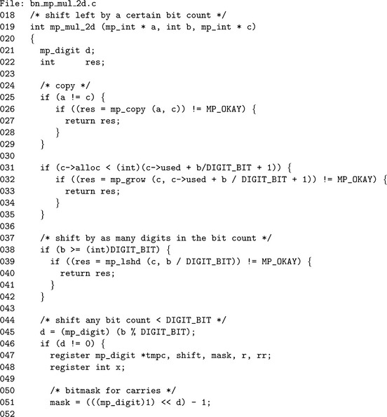
The shifting is performed in place, which means the first step (line 25) is to copy the input to the destination. We avoid calling mp_copy() by making sure the mp_ints are different. The destination then has to be grown (line 32) to accommodate the result.
If the shift count b is larger than lg(β), then a call to mp_lshd() is used to handle all the multiples of lg(β), leaving only a remaining shift of lg(β)–1 or fewer bits left. Inside the actual shift loop (lines 61 to 71) we make use of pre-computed values shift and mask to extract the carry bit(s) to pass into the next iteration of the loop. The r and rr variables form a chain between consecutive iterations to propagate the carry.
4.5.2 Division by Power of Two
Algorithm mp_div_2d. This algorithm will divide an input a by 2b and produce the quotient and remainder. The algorithm is designed much like algorithm mp_mul_2d by first using whole digit shifts then single precision shifts. This algorithm will also produce the remainder of the division by using algorithm mp_mod_2d (Figure 4.13).
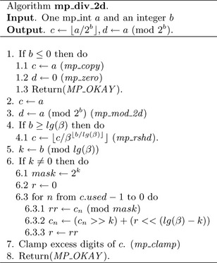
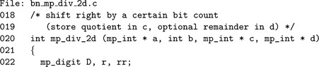
The implementation of algorithm mp_div_2d is slightly different than the algorithm specifies. The remainder d may be optionally ignored by passing NULL as the pointer to the mp_int variable. The temporary mp_int variable t is used to hold the result of the remainder operation until the end. This allows d and a to represent the same mp_int without modifying a before the quotient is obtained.
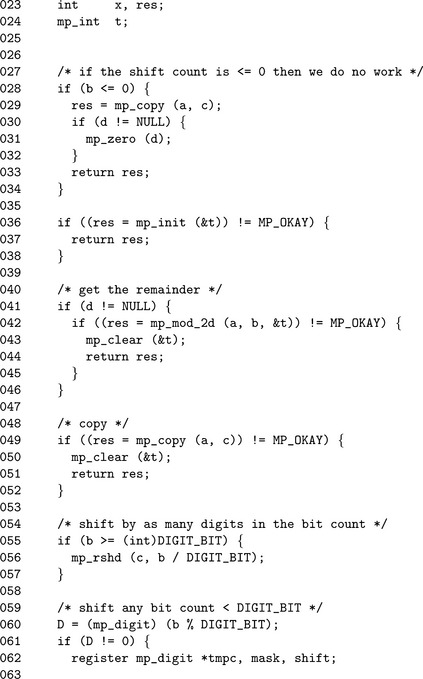
The remainder of the source code is essentially the same as the source code for mp_mul_2d. The only significant difference is the direction of the shifts.
4.5.3 Remainder of Division by Power of Two
The last algorithm in the series of polynomial basis power of two algorithms is calculating the remainder of division by 2b. This algorithm benefits from the fact that in twos complement arithmetic, a(mod 2b) is the same as a AND 2b −1.
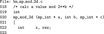
Algorithm mp_mod_2d. This algorithm will quickly calculate the value of a(mod 2b). First, if b is less than or equal to zero the result is set to zero. If b is greater than the number of bits in a, then it simply copies a to c and returns. Otherwise, a is copied to b, leading digits are removed and the remaining leading digit is trimmed to the exact bit count (Figure 4.14).
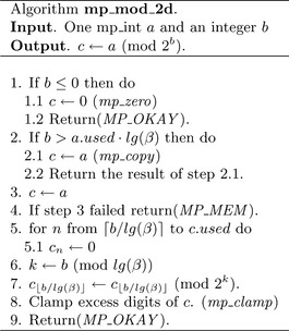
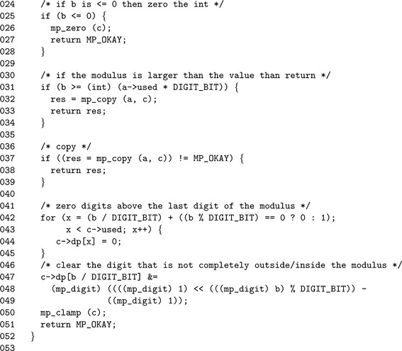
We first avoid cases of b ≤ 0 by simply mp_zero()′ing the destination in such cases. Next, if 2b is larger than the input, we just mp_copy() the input and return right away. After this point we know we must actually perform some work to produce the remainder.
Recalling that reducing modulo 2kand a binary “and” with 2k−1 are numerically equivalent we can quickly reduce the number. First, we zero any digits above the last digit in 2b (line 42). Next, we reduce the leading digit of both (line 47) and then mp_clamp().
3. Devise an algorithm that performs a. 2b for generic values of b in O(n) time.
3. Devise an efficient algorithm to multiply by small low hamming weight values such as 3, 5, and 9. Extend it to handle all values up to 64 with a hamming weight less than three.
2. Modify the preceding algorithm to handle values of the form 2k−1.
3. Using only algorithms mp_mul_2, mp_div_2, and mp_add, create an algorithm to multiply two integers in roughly O(2n2)time for any n-bit input. Note that the time of addition is ignored in the calculation.
5. Improve the previous algorithm to have a working time of at most ![]() ) for an appropriate choice of k. Again, ignore the cost of addition.
) for an appropriate choice of k. Again, ignore the cost of addition.
2. Devise a chart to find optimal values of k for the previous problem for n= 64 ![]() . 1024 in steps of 64.
. 1024 in steps of 64.
2. Using only algorithms mp_abs and mp_sub, devise another method for calculating the result of a signed comparison.