
9
Logical Link Control and Adaptation Protocol
Logical Link Control and Adaptation Protocol (L2CAP) takes data from higher layers of the Bluetooth stack and from applications and sends it over the lower layers of the stack. L2CAP passes packets either to the Host Controller Interface (HCI), or in a host-less system, L2CAP passes packets directly to the Link Manager (LM).
Figure 9–1 shows L2CAP’s position in the Bluetooth stack for the cases with and without a Host Controller Interface. Note that L2CAP transfers data, not audio (though protocols such as voice over IP are regarded as data and would use L2CAP packets if transferred over a Bluetooth system).
L2CAP has many functions:
- Multiplexing between different higher layer protocols, allowing them to share lower layer links.
- Segmentation and reassembly to allow transfer of larger packets than lower layers support.
- Group management, providing one-way transmission to a group of other Bluetooth devices.
- Quality of service management for higher layer protocols.
Figure 9–1 L2CAP’s position in the Bluetooth protocol stack.
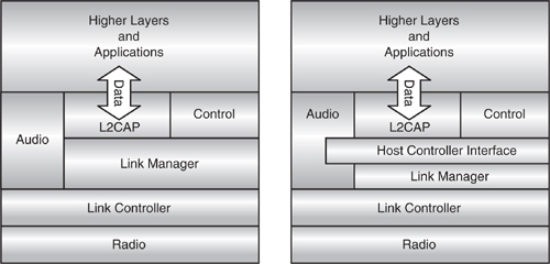
L2CAP relies on ACL connections to pass data reliably from end to end. A separate control function must set up the ACL connections when they are required by L2CAP and close them down when they are no longer required. L2CAP also relies upon the ACL connection’s quality of service to provide the quality of service negotiated with higher layers.
9.1 Multiplexing Using Channels
L2CAP provides multiplexing to allow several higher layer links to pass across a single ACL connection. This allows several different user applications to share an ACL link with the higher layers of the Bluetooth stack (such as the service discovery protocol).
L2CAP uses channel numbers to label packets so that when they are received, they can be routed to the correct place. Because L2CAP entities must also communicate with one another to control channels, a special channel number is reserved for signalling packets used to control L2CAP connections. A second channel number is reserved for receiving multicast packets. A range of channel numbers are available to label L2CAP connections being used by higher layers. These channel numbers are allocated as connections are set up (see section 9.2, L2CAP Signalling).
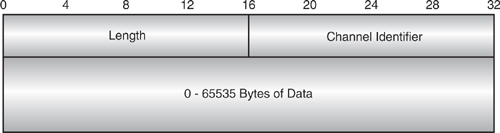
The channel number is carried in a two byte channel identifier, which comes after the length field in every L2CAP packet as shown in Figure 9–2.
The rest of the L2CAP packet carries the data from higher layers. The packet size is variable, and the length of the data is only limited by the two byte field. This allows L2CAP to carry up to 65,535 bytes of data per packet. The large capacity of L2CAP packets allows the packet boundaries of higher layer protocols to be preserved.
Figure 9–2 Structure of an L2CAP packet.
9.2 L2CAP Signalling
The L2CAP signalling channel is allocated the channel ID 0x0001. It is used to send control information between peer L2CAP entities to handle connecting, configuring, and disconnecting L2CAP connections. Bluetooth has rules for naming the signals which follow a convention commonly used in communications protocols. These rules are illustrated in Figure 9–3.
Figure 9–3 Conventions for naming L2CAP signals.
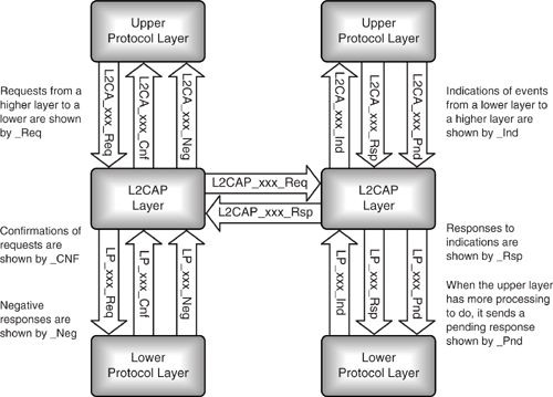
The rules for naming signals are:
- Prefix signals between peers at the same layer with the protocol’s initials (e.g., L2CAP).
- Prefix signals between higher and lower layers with the lower layer’s initials (e.g., L2CA).
- Suffix requests from a higher layer to a lower layer with “Req”.
- Suffix confirmations of requests sent from a lower layer to an upper layer with “Cnf”.
- If a response from a lower layer is negative, the suffix “Neg” may be used instead of “Cnf”.
- Suffix indications of events sent from a lower layer to a higher layer with “Ind”.
- Suffix responses to indications sent from a higher layer to a lower layer with “Rsp”.
- If a response to an indication requires further processing, “Rsp” may be replaced with “Pnd”, which is an abbreviation for pending response.
All requests from a higher layer to a lower layer must be acknowledged by a corresponding confirmation, but not all indications from a lower layer require a response or pending response.
9.2.1 L2CAP Signalling Structures
As with other layers of the Bluetooth stack, L2CAP signals use the common structure shown in Figure 9–4. The first byte has the OpCode identifying the contents of the signal. This is followed by an identifier field. Many commands may be sent in one packet, and the responses to these may return split across more than one packet, making it difficult to match up responses with original requests. To make it easier to pair up responses and requests, a new identifier is used for each request, and the identifier is copied from the request into the response.
L2CAP starts a timer when a message is sent, and if no response arrives, the message is re-sent. In this case, the original identifier is recycled, so if the command was received and it was the response that was lost, the responding device knows it should send another response, but it shouldn’t execute the command twice. Apart from retransmissions of commands, the identifiers shouldn’t be reused for 6 minutes; this allows 255 commands to be sent in 6 minutes (you might think the 1-byte field length for the identifier would allow 256 identifiers rather than 255, but the identifier 0x0000 is not used).
Figure 9–4 Structure of an L2CAP command.
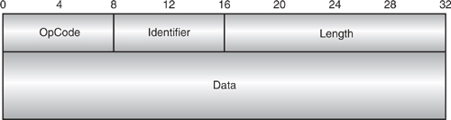
After the identifier field comes a length field; this gives the length of the data field. Many commands can be sent within one L2CAP packet; they are simply lined up one after another as shown in Figure 9–5. Different implementations of L2CAP can support different lengths of L2CAP packets. The maximum size of packet payload supported is called the Maximum Transmission Unit, or MTU. All implementations of L2CAP are required to support a packet payload length of at least 48 bytes for signalling, so unless the MTU is known, a signalling packet’s payload should be restricted to this length.
If a signalling packet is received which is longer than the MTU, it is rejected. A special reject packet is available which has a reason field giving the reason for the command being rejected. The reject packet is shown in Figure 9–6. It contains an identifier for the command being rejected. Of course, if many commands are being rejected because they are in a packet payload larger than the receiving device’s MTU, the receiving device may not be able to read all the commands, so this poses a potential problem copying identifiers into reject packets. To get around this problem, if a command packet payload is received which is larger than the receiving device’s MTU, all commands in the packet are rejected together using one reject packet. In this case, the identifier copied into the reject packet is the one taken from the first command in the packet.
Version 1.0 of the Bluetooth standard defines three reasons for rejecting a packet; these are:
- Command not understood—In this case, no data is returned.
- The request had an invalid connection identifier—The identifier is returned in the data field.
Figure 9–5 L2CAP signalling packet containing multiple commands.
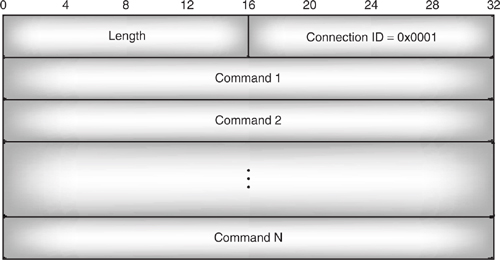
Figure 9–6 Structure of the L2CAP reject packet.
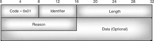
- The command packet payload was larger than the rejecting device’s MTU—In this case, the correct size of MTU is returned in the data field.
The reason field is two bytes long, so there is plenty of scope for future versions of the standard to define more reject reasons.
9.3 Establishing A Connection
L2CAP uses ACL links to reliably pass data without errors across the lower layers of the Bluetooth stack. Bluetooth’s broadcast transmission is not reliable, so broadcast should not be used, and L2CAP implementations should use point to point ACL links.
To establish a link, the higher layer protocol will send a request to the L2CA layer to connect. If there is no existing ACL connection, this causes L2CAP to send a request to a lower layer protocol to connect. As shown in Figure 9–1, the protocol below the L2CA layer could be either HCI or LM. Figure 9–7 illustrates the case where there is an HCI layer and L2CAP uses HCI to establish an ACL connection. (In this diagram, messages in italics are implementation-dependent, but use names suggested by the Bluetooth specification. Messages not in italics have formats fully defined by the specification.)
As can be seen from Figure 9–7, the steps involved in setting up an ACL connection are quite complex. This diagram illustrates how L2CAP relies on the rest of the protocol stack to provide reliable data connections.
Messages 8 and 9 show HCI on the side accepting the connection, indicating to the L2CAP layer that it has been paged and a decision is required on whether or not to connect. In the L2CAP standard, there are no primitives defined for the lower layers to indicate that a connection request has been received. Instead there is just an LP_ConnectInd primitive, which indicates that the connection has been completely set up. One could argue that the writers of the standard intended that the baseband should be set to auto-accept connections, in which case, it would only be informed after the connection had been fully set up. In this case, only having an LP_ConnectInd primitive makes sense. However, it is possible that some implementers may want more control over the connections, as having the ability to reject them earlier on in the setup process allows a device to save both bandwidth and power.
Figure 9–7 Messages for setting up an L2CAP connection over HCI.
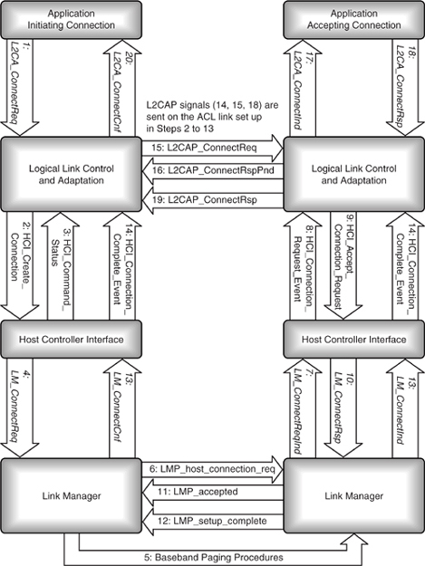
If the device was set to auto accept connections, Messages 8 and 9 would be omitted; otherwise, it makes sense to send the message to L2CAP as shown.
Also note in the diagram the two sets of messages, 13 and 14, which are sent up the stack when the connection is complete. The L2CAP entities on both sides must know that the ACL link is in place before they can exchange L2CAP messages. In a system with an HCI, message 14, the HCI_Connection_Complete event, indicates to both sides that the ACL connection is available for exchange of L2CAP messages. The same HCI event is used on both the initiating and accepting sides, and as it is sent almost simultaneously on both sides, the two sets of messages are given the same number.
Figure 9–8 shows a general case with L2CAP connecting via a lower layer protocol. In a hostless system, the lower protocol layer could be the Link Manager. This illustrates successful establishment of a connection across the lower layers, but if the lower protocol failed to establish a connection, LP_ConnectCnfNeg messages would be sent in place of the LP_ConnectCnf.
In this diagram, the stage of accepting the connection between receiving a paging packet and configuring the connection has been left out, so, unlike the previous diagram, it is assumed that the baseband has been set up to accept connections without informing higher layers until they are complete.
Once an ACL connection is established across the lower layers, L2CAP packets can be sent across it. In Figures 9–3, 9–7, 9–8, L2CAP packets are shown being exchanged directly between peer L2CAP entities, but, of course, they are transferred across the lower layers of the stack in lower layer Protocol Data Units (PDUs). The first message sent is an L2CAP_ConnectReq (Figure 9–9). In addition to the usual OpCode, identifier, and length fields, the message carries the following parameters:
- A Protocol Service Multiplexer (PSM) value specifying the protocol using this connection.
- A source Channel ID (CID), the Channel CID allocated to the connection by the initiating device.
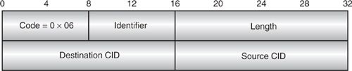
An L2CAP_ConnectionRsp message is sent in response to the connection request. The response contains the following parameters:
- The destination Channel ID (CID) containing the CID which will be used for the connection by the responding device. This must be stored, as it will be needed later when disconnecting.
- The source Channel ID (CID), which is copied from the L2CAP_ConnectionReq.
- A result field, which gives the status of the connection: successful setup, pending setup, refused for security reasons, or refused due to lack of resources.
- If the connection is pending, a status field explains what operation is waiting to complete. This can be authentication, authorisation, or an unspecified operation.
The structure of the L2CAP_ConnectionRsp packet is shown in Figure 9–10.
Figure 9–8 Messages for setting up an L2CAP connection over a lower protocol.
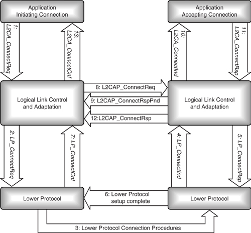
Figure 9–9 Structure of an L2CAP connection request packet.
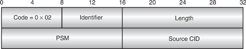
Figure 9–10 Structure of an L2CAP connection response packet.

9.4 Configuring A Connection
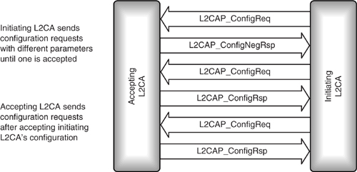
Once a connection has been established, it must be configured. The initiating L2CA begins by sending configuration requests in L2CAP_ConfigReq messages. If these are rejected, an L2CAP_ConfigNegRsp message is returned (or a command reject is sent if the request is badly formed—for instance, with an illegal channel ID), and the initiating device must try again with different parameters until its parameters for the connection are accepted with an L2CAP_ConfigRsp message.
Once the initiating device has configured the outbound channel going to the accepting device, the accepting device can configure the return channel using the same set of messages as shown in Figure 9–11.
If two devices have difficulty deciding on a mutually agreeable set of parameters, L2CAP_ConfigReg and L2CAP_ConfigNegRsp messages could be exchanged for a very long time. When devices abandon attempts to configure the channel is up to each implementation, but the standard sets an absolute maximum time of two minutes; after that time, the devices either work with the parameters they have or close down the connection.
Figure 9–11 Message sequence chart for L2CAP configuration.
Parameters which can be configured are:
- Maximum Transmission Unit (MTU).
- Flush timeout.
- Quality of service.
9.4.1 Maximum Transmission Unit
The MTU specified in an L2CAP_ConfigReq message is the maximum size in bytes of packet payload a device is willing to accept. As mentioned above, if the MTU requested is larger than a device can support, it will reject the request with a reject packet containing the MTU it can handle. Then it is up to the requesting device to decide whether to accept that size MTU or abandon the connection.
9.4.2 Flush Timeout
The flush timeout gives the amount of time in milliseconds that a device will spend trying to transmit an L2CAP packet segment before it gives up. If a packet segment does not get through before the flush timeout is exceeded, the segment can’t get through and the whole packet is flushed (thrown away). The flush timeout controls how many times the baseband can retransmit a packet. Since a baseband slot pair takes 1.25 ms if the flush timeout is set to 1, it is below the minimum polling interval of the baseband, so the value of 1 is taken to mean no retransmissions. The value 0xFFFF also has a special meaning: It is used when there is no timeout and the link manager keeps retransmitting the packet until link manager decides the link has been lost.
The flush timeout is applied to the channel in the same direction as the L2CAP_ConfigReq travels; that is to say, the transmitting device tells the receiving device what flush timeout it wishes to implement. If no flush timeout is specified, the default value is 0xFFFF (retransmit until the link is lost).
9.4.3 Quality of Service
The quality of service option can select best effort, or a guaranteed quality of service. Keep in mind that a wireless link subject to interference cannot guarantee quality of service, it can only configure the channel so that it does not compromise quality of service by accepting more traffic than it can handle. Values such as token rate, token bucket size, peak bandwidth, latency, and delay variation can also be negotiated.
The quality of service is applied to the channel in the same direction that the L2CAP_ConfigReq travels; that is to say, the transmitting device tells the receiving device what quality of service it wishes to implement. More details of how L2CAP handles quality of service can be found in Chapter 17.
9.5 Transferring Data
Once the channel has been created and configured, it can be used to transfer data. How the higher layers pass data to and from the L2CA layer is implementation dependent, but the standard suggests that L2CA_DataWrite and L2CA_DataRead signals can be used as shown in Figure 9–12. An L2CAP_Data message is used to carry the data between peer L2CA entities.
If a higher layer tries to send a packet which would exceed the receiving end’s MTU, then only the first MTU bytes are sent.
9.5.1 Segmentation and Reassembly
Some higher layer protocols use packet sizes larger than those which Bluetooth can handle, so L2CAP provides segmentation of higher layer packets going down the stack, and reassembles them as they pass up the stack (see Figure 9–13).
L2CAP data packets have a 4 byte header which is transmitted with the data. Naturally, the more data that can be transmitted with one header, the more efficient the system is, so L2CAP packets are very large, carrying up to 65,535 bytes of data.
The Host Controller Interface (HCI) uses smaller packets. The actual size of the packet is implementation-dependent because some embedded systems will have very little memory and won’t be able to buffer large packets. However, HCI also has headers, and if packets become too small, it would be inefficient, so the specification says that all implementations must support packets carrying up to 255 bytes of data. Because HCI packets are smaller than L2CAP packets, the L2CAP packets may have to be segmented into the data portions of several HCI packets. When the packets come to be reassembled, the L2CAP layer has to know where the start of each L2CAP packet is, so the HCI Packet Boundary (PB) flag is used to identify which HCI packet has the start of the L2CAP packet.
Figure 9–12 L2CAP data exchange.
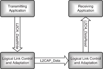
Figure 9–13 Segmentation and transport of L2CAP packets.

The HCI can use several different transport layers. If USB (Universal Serial Bus) is used, each HCI packet is sent in one USB transaction, but a USB transaction may involve the transfer of several 64 byte USB frames. Whatever transport layer is used, the same HCI packets are reassembled on the lower side of the HCI layer as were transmitted on the upper side.
The baseband uses a variety of different packets with varying data capacities. The lower layers of the Bluetooth stack may have to pick different packet types on a slot by slot basis. For example, some slots may be reserved for communicating with Slaves in low power modes such as Sniff or Park, so a link which normally uses 5 slot packets may sometimes only have space for a single slot packet as other slots have been reserved. Because the slot sizes available may change moment by moment, only the lower layers of the stack can decide what size baseband packet to use. Therefore, there is another level of segmentation which is performed in the lower layers of the stack, where HCI packets may be split up into the payloads of several baseband packets.
It is still important that the start of L2CAP packets is recognisable, so the baseband logical channel field identifies packets which carry the start of a new L2CAP packet.
Each baseband packet may have to be retransmitted several times, but unless the link is lost altogether, the baseband will reliably transfer packets in order, and any repeats received will be filtered out (as long as broadcast is not used). So even though L2CAP packets may be split up and reassembled several times in passing through the Bluetooth protocol stack, they can always be delivered reliably and reassembled in the right order, with the start of each L2CAP packet easily identifiable.
9.6 Disconnecting And Timeouts
There are two ways for an L2CAP channel to be closed down: a higher layer protocol or service can request that it be closed down or it can time out.
Once data transfer has finished, the protocol or service using the channel can send an L2CA_DisconnectReq to request disconnection. The exact format of this message is implementation specific, but it should contain the ID of the channel to disconnect.
When L2CAP receives the L2CA_DisconnectReq, it causes an L2CAP_Disconnect-Req packet to be sent across the baseband link to the peer L2CAP at the other end of the channel. At the same time, L2CAP stops sending and receiving data on the channel. Any queues of data for transmission are emptied, and any data received is just discarded.
The L2CAP_DisconnectReq packet is shown in Figure 9–14. Because each L2CAP connection has a different channel ID at each end of the connection, the disconnect request contains two channel IDs: the ID for the source end of the connection can be copied from the L2CA_DisconnectReq, and the Channel ID for the destination end was passed in the connection response and stored in L2CAP when the channel was first set up.
The device receiving the L2CAP_DisconnectReq discards all data queued for transmission on that channel, since the device which sent the L2CAP_DisconnectReq is discarding all data it receives anyway. The device receiving the L2CAP_DisconnectReq replies with an L2CAP_disconnectRsp as shown in Figure 9–15.
Figure 9–14 Structure of an L2CAP disconnect request packet.
When the L2CAP that sent the L2CAP_DisconnectReq receives the L2CAP_DisconnectRsp, it can inform the upper protocol layer of the result of its disconnect request. A result with the code 0x0000 is sent back to indicate success. If no response is received, 0xEEEE is sent back to indicate that the request timed out. The upper layer protocol or service can then decide whether to re-issue the request. The exchange of messages used to disconnect an L2CAP channel is shown in Figure 9–16.
In addition to channels being disconnected by the upper layers sending messages, they can also be disconnected as a result of timeouts. Every time L2CAP sends a signal, it starts a Response Timeout Expired (RTX) timer. The length of the RTX timer varies between implementations, but it must start between one second and one minute. Obviously, it doesn’t make sense to retransmit a packet while the baseband is still attempting to transmit it, so the RTX timer should be set so that retransmission doesn’t start until after the baseband has given up transmitting the packet. If the flush timeout is infinite so the baseband keeps trying to retransmit until the link is lost, then L2CAP should not retransmit at all.
If the timer expires before the response is received, either a duplicate message can be sent or the channel can be disconnected. If a duplicate message is sent, the RTX timeout for the duplicate is double the previous timeout. It is up to the implementers to decide how many times to retransmit, but obviously it doesn’t make sense to keep trying forever if the message isn’t getting through. In these cases, the baseband link has probably been lost, so if no response is received within 60 seconds, the channel should just be disconnected without sending an L2CAP_DisconnectReq.
Figure 9–15 Structure of an L2CAP disconnect response packet.
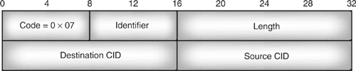
Figure 9–16 Message sequence chart for disconnecting an L2CAP channel.

There is one exception to disconnecting after 60 seconds: If the far end returns a response which indicates it has more processing to do, then an Extended Response Timeout Expired (ERTX) timer may be used instead of the RTX timer. The ERTX timer is just like the RTX timer except that where the RTX timer can take any value between one second and one minute, the ERTX timer’s range is between one minute and five minutes. The ERTX timer must be within this range, but its exact value is up to the implementation.
As each signal is sent, an RTX timer is started, and this can be changed to an ERTX timer where the far end of a link returns a pending response (for example, an L2CAP_ConnectRspPending, which indicates the far end is processing a connect request). This means that there can be many RTX and ERTX timers running simultaneously.
9.7 Connectionless Data Channels
L2CAP provides connectionless channels to connect a device to a group of one or more other devices in a single direction.
Connectionless channels cannot be configured for quality of service. This is because trying to negotiate the same quality of service with a whole group of devices could take forever, so it’s only practical to use best effort (which is the default quality of service). L2CAP sends connectionless data to all devices in a group, but because connectionless channels are best effort, the data is not guaranteed to arrive.
Transmit connection IDs are set up as connectionless channels are established, but the same L2CAP channel Identifier 0x0002, is used as the receive end of all connectionless channels.
With connection oriented L2CAP traffic, a Protocol Service Multiplexer (PSM) value is associated with a particular connection ID, but this cannot be done with connectionless traffic because all connectionless traffic is received on the same connection ID (0x0002). To provide a way of associating a PSM value with connectionless traffic, the PSM value is added into every connectionless L2CAP packet at the start of the payload data field as shown in Figure 9–17.
Figure 9–17 Structure of a connectionless L2CAP packet.

The PSM field takes up at least two bytes. The least significant bit of each byte in the PSM field is a continuation flag. If it is zero, there are more bytes to come; if it is 1, then this is the last byte of the PSM field.
Some PSM values are defined by the Bluetooth standard; these are:
- 0x0001 service discovery protocol.
- 0x0003 RFCOMM, serial port emulation.
- 0x0005 TCS-BIN, Telephony Control protocol Specification - Binary.
- 0x0007 TCS-BIN-CORDLESS.
PSM values 0x1001 upwards are available for assigning to services as L2CAP connections are established (although because of the rules for the continuation flag, not all values of PSM are legal as the least significant byte must be odd and all other bytes in a PSM must be even).
9.8 Enabling And Disabling Incoming Connectionless Traffic
It is possible that higher layer applications might only want to receive traffic addressed directly to them, so L2CAP defines messages to disable connectionless traffic.
The exact format of the message to disable connectionless traffic is implementation dependent, but the message should include a Protocol Service Multiplexer (PSM) parameter. Traffic destined for one protocol or service can be disabled by specifying its PSM value. For example, the message sequence chart at the right of Figure 9–18 shows connectionless traffic destined for RFCOMM being disabled by a message specifying the PSM reserved for RFCOMM, which is 0x0003. The result of the L2CA_DisableCLT is simply success or fail; no reason for failure need be given.
Figure 9–18 Message sequence charts for disabling connectionless traffic.
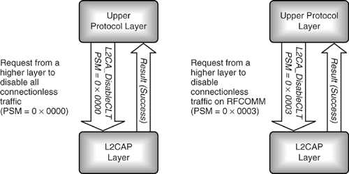
To disable all connectionless reception, the PSM parameter is set to the invalid value 0x0000 as shown at the left of Figure 9–18. Implementations are allowed to only support blocking all connectionless reception; in this case, any attempts to block with the PSM parameter being anything other than zero would fail.
An L2CA_EnableCLT message works similarly to the L2CA_DisableCLT and enables reception of connectionless packets. It also has a PSM parameter which works the same way as the PSM parameter for L2CA_DisableCLT, with an all zero value specifying that connectionless reception should be enabled for all protocols and services.
9.9 Handling Groups
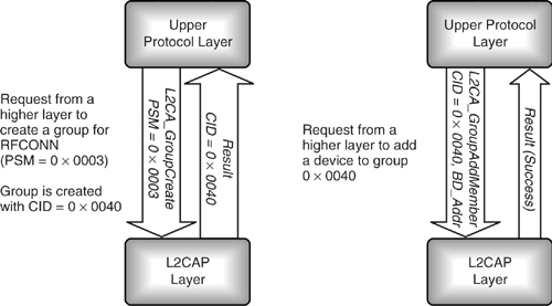
To send connectionless traffic, first an L2CAP group must be created. As with all messages between L2CAP and higher layer protocols, the exact format of the message is implementation specific, but it should include a PSM field for the protocol or service which will transmit to the group. The response carries the connection ID (CID), which will be used by the upper protocol layer to transmit to the group. The connection ID is also used to add devices to the group; this is done by sending the group’s connection ID and the Bluetooth device address of the device to be added. For instance, the message sequence chart at the left of Figure 9–19 shows a group being created for RFCOMM (PSM = 0x0003). The result returns an ID of 0x0040 for the new group. The chart at the right shows a device being added to the newly created group. The parameters for the L2CA_GroupAddMember request are the connection ID and the Bluetooth device address of the device to be added; the reply is a success (0x0000) or failure (0x0001) result.
Figure 9–19 Message sequence chart for creating a connectionless group and adding a device.
An L2CA_GroupRemoveMember command is also available; this is similar to the L2CA_GroupAddMemberCommand and takes the same parameters: an ID to specify the group from which the device is to be removed and the Bluetooth device address of the device to be removed. The result is either success (0x0000) or failure (0x0001) if the specified device was not a member of the specified group.
L2CA_GroupClose may be used to close down a connectionless channel. This request takes a single parameter: the ID of the connection to be closed.
Finally, the L2CA_GroupMembership request may be used to find the Bluetooth device addresses of devices in a group. The CID of the group is passed as a parameter of L2CA_GroupMembership; the result is success (0x0000) or failure (0x0001). If success, then a list of Bluetooth device addresses is also returned in the result. The list comes after the success code.
A peculiarity of the Bluetooth standard is that while devices must be individually added to a group, when data is sent to the group, it is permissible to send it to devices which are not in the group. Perhaps this was originally specified because it would allow the baseband to broadcast L2CAP data. Whatever the original reason, the version 1.0 baseband broadcast mechanism has flaws which mean it cannot reliably be used for L2CAP data, so it is difficult to see why bandwidth should be wasted transmitting an L2CAP packet to devices not in the group it is intended for. It is unlikely that any implementation would choose to waste bandwidth in this way, but applications writers should be aware that connectionless L2CAP traffic may be sent to devices outside the group it is intended for; so where privacy is important, encryption should be used.
Figure 9–20 Structure of an L2CAP echo request packet.
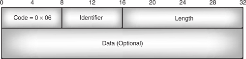
9.10 Echo And Ping
Echo requests ask the peer L2CAP device to send an echo response back. They can be used simply to test a link, or they can be used to pass implementation specific commands, since they include a data field as shown in Figure 9–20. Naturally, any devices using the echo request data field to extend the L2CAP command set should be careful to ensure that there is a matching implementation at the other end or their commands could have unexpected results!
The echo response packet matches the echo request in everything but the packet’s code. The identifier from the echo request is copied to the echo response, as is the length field and any data (see Figure 9–21).
An upper protocol layer can initiate an L2CAP echo request and response exchange using the L2CA_Ping request. This request is implementation dependent, but it should take the following parameters:
- BD_ADDR—Bluetooth device address of device to which the L2CAP_EchoReq will be sent.
- ECHO_DATA—A pointer to the data to be sent in the L2CAP_EchoReq (this is optional).
Figure 9–21 Structure of an L2CAP echo response packet.

Figure 9–22 Message sequence chart for L2CAP ping and echo.
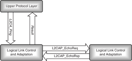
- Length—Two bytes giving the length of the ECHO_DATA (if there is no data, length = 0).
The result begins with a success (0x0000) or fail (0x0001) code. The ping fails when an echo request is sent but L2CAP times out before a response is received (refer to Figure 9–22).
9.11 Get Information
L2CAP has L2CAP_InfoReq and L2CAP_InfoRsp messages, which can be used to exchange information between peer L2CA layers.
Figure 9–23 shows that the L2CAP_InfoReq packet. The information type parameter specifies the type of information being requested. Version 1.0 of the standard only specifies one information type which can be retrieved: 0x00001 gets the value of the MTU on the connectionless channel.
Figure 9–23 Structure of an L2CAP information request packet.
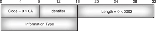
Figure 9–24 Structure of an L2CAP information response packet.
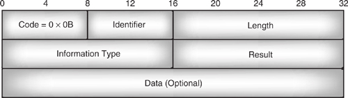
Figure 9–24 shows that the L2CAP_InfoRsp information type matches the information type sent in the request; the result is 0x0000 for success or 0x0001 for failure. If the information request was successful, the data field holds the requested information. For the connectionless MTU, this takes two bytes.
If an upper protocol layer wants to get information from L2CAP, it sends an L2CA_GetInfo request. The exact format of this request is implementation-dependent, but it should include the Bluetooth device address of the device to which the request will be sent and the information type field to identify the information being requested (for version 1.0 implementations, the information type must be 0x0001 to request the connectionless MTU).
The result of the L2CA_GetInfo request carries a result parameter, which can take the following values:
- 0x0000—Success, a response was received; this result will be followed by MTU data.
- 0x0001—The request was not supported by the local device, so there is no data.
- 0x0002—The request was not supported by the remote device, so there is no data.
- 0x0003—The request timed out before a response was received, so there is no data.
If the request was successful, a pointer to the requested data and a size field giving the length of the data are also returned. (For the connectionless MTU request; the response is two bytes long, so the length field will be 0x0002.) Figure 9–25 shows how the L2CA_GetInfo request triggers the L2CAP_InfoReq and L2CAP_InfoRsp messages between peer L2CA layers.
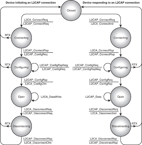
9.12 L2CAP State Machine
Internally, L2CAP has a state machine driven by L2CA signals from higher layers and L2CAP signals carried across lower layers. Figure 9–26 shows the L2CAP state machine for setting up a connection. At any stage, if L2CAP signals fail to appear before a Response Timeout (RTX), the channel will be closed. (Notice that the RTX applies only to the L2CAP signals. The standard does not specify timeouts for the L2CA signals from higher layers.)
Figure 9–25 Message sequence chart for L2CA_getInfo.
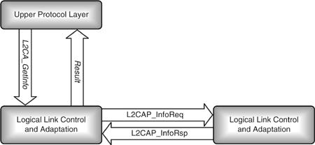
Figure 9–26 shows how higher layers drive L2CAP, and how L2CAP peers communicate. It does not show signals going to lower protocol layers, so data transfer in the open state does not show the signals used to pass data across the lower layers. For clarity, the diagram only shows data being passed from the initiating device to the responding device, although in reality, data can go in both directions.
Notice that the device which is initiating the connection waits for signals from its higher layer application, so its higher layer application drives it through the states. In this example, the device accepting the connection waits for L2CAP signals from the device initiating the connection, and is driven through states by L2CAP signals. However, its application could also drive the L2CAP connection, for example, by either requesting to reconfigure the link or requesting disconnect.
9.13 Implementation-Dependent Issues
The L2CAP specification does not include many things which are needed to implement the system. The most obvious omission is the exact format of the L2CA primitives used to communicate with higher layers and the LP primitives used to communicate with lower layers. However, there are other issues, not quite so obvious, which any implementor needs to consider. This section highlights a few of those issues.
L2CAP messages which cause L2CAP connections to be dropped are specified, but the L2CAP specification makes no mention of an LP primitive to drop the baseband link. If a Bluetooth device has been set up to keep a connection alive by passing poll packets when there is no data, then links which are not being used by L2CAP could stay up, causing an unnecessary waste of bandwidth and unnecessary power consumption. Implementers of Bluetooth systems need to decide sensible ways for L2CAP to drop baseband links after the last L2CAP connection using a link has closed down.
Figure 9–26 L2CAP state machine.
There is a lower protocol message, LP_ConnectInd, which is sent to L2CAP when lower layers have finished setting up a link. This is equivalent to the HCI_Connection_Complete event, which signals to a host that a connection has been set up and configured for use. However, there is no equivalent to the HCI_Connection_Request, which signals to a host that a device has been paged and allows the host to accept or reject the connection before configuration commences. Implementers may wish to add extra primitives to allow information to be passed to L2CAP at the stage when a device has been paged but has not yet configured a connection. If they do not do this, then the device will have to be set to automatically accept connections; otherwise, connections could time out before they have been configured because there is no entity in the system accepting connection requests.
Of course, the functionality described above does not have to be handled by L2CAP. Some implementors choose to add a separate device manager which handles accepting lower layer connections for L2CAP and also handles tearing down ACL connections when L2CAP no longer needs them.
9.14 Summary
L2CAP provides the facilities higher layer protocols need to communicate across a Blue-tooth link. These facilities are:
- Establishing links across underlying ACL channels using L2CAP signals.
- Multiplexing between different higher layer entities by assigning each one its own connection ID.
- Providing segmentation and reassembly facilities to allow large packets to be sent across Bluetooth connections.
Higher layer applications and protocols communicate with L2CAP using implementation dependent primitives known as L2CA signals. The standard defines what these signals should do, but the exact implementation can vary from one Bluetooth system to the next.
All applications must use L2CAP to send data. It is also used by Bluetooth’s higher layers such as RFCOMM and SDP, so L2CAP is a compulsory part of any Bluetooth system.