
17
Quality of Service
Simple Bluetooth devices will have one application or protocol using a single link. Different applications and protocols will place different demands on the link. For example, a file transfer wants to move data reliably and as fast as possible; it doesn’t matter if the link is bursty (sometimes fast, sometimes slower when there are errors on the link and packets have to be retransmitted). On the other hand, an application transferring compressed video or audio streams may want a link that is not bursty and may be able to miss a few packets as long as the delay on the link is not too high.
In devices where there are many links operating at once, the bandwidth allocated to each link must be decided. Many applications or protocols will want high bandwidth, but some applications will never require high data rates; for instance, many remote controls will never transfer more than a few bytes a second.
The Bluetooth specification provides Quality Of Service (QOS) configuration to allow the properties of links to be configured according to the requirements of higher layer applications or protocols. The properties which can be configured are:
- The type of QOS—Whether the link guarantees its settings, will just make an attempt at achieving them, or possibly offer no service at all.
- Token rate—The rate at which data may be sent on a link.
- Token rate bucket size—This is a measure of how much storage will be available in the stack for data. Bursty links will most likely need more storage than links which flow evenly.
- Peak bandwidth—The maximum rate that back to back packets can be sent—that is to say, packets all dedicated to one link with no other links getting to transfer in between them.
- Latency—The delay between data being ready to send and being sent out over the radio for the first time.
- Delay variation—The spread between the maximum and minimum delay across a link.
Figure 17–1 shows how messages throughout the Bluetooth protocol stack are used to control QOS. Messages configuring and setting up QOS flow vertically up and down the layers of the stack, but there is also horizontal messaging when peer entities on different devices negotiate QOS. Both the link manager (LM), and the Logical Link Control and Adaptation Layer (L2CA) are involved in peer to peer negotiations to configure QOS for a link.
Figure 17–1 Quality of service messaging.

The L2CA uses the Logical Link Control and Adaptation Protocol (L2CAP) to request a particular QOS on a link. The L2CA at the far end of the link tries to achieve the requested QOS by asking its local link manager. On systems with an HCI, L2CA communicates with LM via HCI as shown in Figure 17–1.
The link manager configures and controls the baseband links. So it is LM which actually implements QOS policies. LM has various means to try to meet the QOS which L2CA requests.
To ensure that data is removed from its transmission buffers fast enough to satisfy the token rate LM has guaranteed on a connection, LM guarantees a polling interval, that is to say a maximum gap between subsequent transmissions on a link. If the packet type on a connection changes, the amount of data transferred in each packet will change, so the polling interval may also change.
Under some circumstances, the polling interval will not change even if packet types change. This is because the poll interval is the maximum time between transmissions from the Master to a particular Slave. The gap between transmissions affects the latency (delay) on a connection, as well as the bandwidth available to a Slave. So if increasing the poll interval would take latency beyond what has been guaranteed, then the poll interval won’t be changed.
The link manager can also affect the overall behaviour of the system according to the QOS settings it has accepted. If the link manager accepts a connection with a maximum possible token rate and a service type of guaranteed, then the link manager should try to meet this by refusing all connection requests from remote devices. It could also maximise bandwidth available to the ACL connection by stopping periodic page and inquiry scans (it doesn’t want to accept new connections anyway, so there’s not a lot of point in scanning for new devices in the area).
Link managers at opposite ends of a link must agree on the QOS they are trying to achieve: It is no good to one link manager successfully transmitting lots of packets if the LM at the other end doesn’t have the resources to receive them and forward them up the stack. So in addition to controlling the baseband layers, LM performs end to end negotiations of QOS using the LMP. When L2CAP requests a particular QOS configuration, link managers at the opposite ends of a link negotiate. If they agree that they can achieve the requested QOS, the L2CAP which requested it is informed, and it can tell its peer L2CAP
that QOS configuration has succeeded; otherwise, QOS configuration fails and L2CAP must decide whether to give up or try again with a different QOS. This decision is actually taken by the application above L2CAP which requested the QOS in the first place.
It should be obvious by now that QOS involves some complex tradeoffs in the management of a device’s ACL links. Sometimes the required QOS won’t be possible because of interference on the radio link, and sometimes it won’t be possible just because the device doesn’t have the capacity available. To cope with this, the Bluetooth specification provides a variety of messages at various levels to negotiate acceptable levels in QOS, and to signal when those levels just can’t be met.
17.1 Requesting QOS
When a link is first set up, there is usually a negotiation phase where the parameters for the link are configured. This is the point where security is usually configured; QOS can be configured at this point too. Just as with security, the QOS can be changed later on if higher layer applications or protocols need to change it. This might be because a new service wants to use the link, or because the radio environment has changed and the requested QOS is no longer realistic. This section explains how the layers of the Bluetooth protocol stack interact to change QOS on a link in response to a QOS request.
17.1.1 QOS Requests from Higher Layers to L2CA
A service, application, or higher level protocol which needs a certain QOS requests it at the time a Logical Link Control and Adaptation Layer (L2CA) connection is set up by sending a configuration request to L2CA. The exact format of exchanges between higher layers and L2CA is implementation-specific, but the Bluetooth specification suggests possible primitives.
L2CA_ConfigReq is used to request configuration of a channel. Among its parameters, this request includes a channel identifier and a flow specification which gives the QOS required on the channel. How L2CA responds to this message depends upon the state of the L2CA channel when the request is sent:
- If the channel is closed, then an L2CA_ConfigRspNeg is returned to the upper layer indicating that the channel cannot be configured.
- If the channel is in configuration state, then L2CA begins QOS negotiation.
- If the channel is open, data transmission on the channel is stopped at a convenient point (say at the end of an L2CAP packet), then L2CA moves the channel to the configuration state and begins QOS negotiation.
To begin QOS negotiations, an L2CAP_ConfigReq Message is sent to the L2CA at the other end of the channel (see Figure 17–1) and an RTX timer is started to check the response time.
17.1.2 L2CAP Peer-to-Peer QOS Request
To configure QOS at the Logical Link Control and Adaptation (L2CA) layer, a configuration packet is sent. The structure of this packet is shown in Figure 17–2. The packet begins with the fields common to all L2CA signalling commands:
Figure 17–2 L2CA QOS configuration request packet.
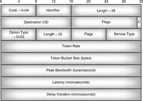
- Code—Identifies the type of command. The code 0x04 identifies the configuration command.
- Identifier—This field is changed for each request, and copied into the response, so that responses and requests can be matched up.
- Length—Identifies the overall length in bytes of the data part of the command (this does not include the code, identifier, and length fields).
These are followed by four fields common to all L2CA configuration request commands:
- Destination channel ID—Identifies the endpoint of the channel on the device which is receiving the command.
- Flags—Although this is a 2-byte field, only the least significant byte is used in versions 1.0 and 1.1 of the specification. This is a continuation flag. If this is 1, then more configuration requests will follow; if it is 0, then the channel is configured, and the remote device may enter the open state.
- Option type—Set to 0x03, this indicates the configuration request deals with QOS.
- Option length—The length of the remaining option parameters.
The remaining fields contain the configuration options for QOS.
- Flags—In versions 1.0 and 1.1, this is reserved for future use, and must be set to zero.
- Service type—The level of service; possible values are no service, best effort, or guaranteed. If best effort is chosen, the device receiving the request has three options: it may choose to ignore the rest of the parameters, it may try to satisfy the request but not respond, or it may respond with the settings it believes it can achieve.
- Token rate—The rate at which an application using the channel will be granted credit. It is measured in bytes per second. An application may send data up to the token rate, but shouldn’t exceed it. 0xFFFFFFFF is actually a value larger than the maximum capacity of a Bluetooth link, so it has a special meaning: it requests the maximum available rate. 0x00000000 also has a special meaning: rather than indicating zero token rate, it indicates that the requester is not specifying a token rate.
- Token rate bucket size—The size of the token bucket, that is to say the size of buffer which should be made available to receive data. Bursty data needs a large token bucket; continuous data needs a small bucket, or none at all (predictably, if no token bucket is needed, this is indicated by sending a bucket size of 0x00000000). Again the value 0xFFFFFFFF has a special meaning: it means that the largest possible token bucket should be allocated.
- Peak bandwidth—The maximum rate at which applications may send back to back packets. The value 0x00000000 does not say that maximum bandwidth is zero, rather it says that the maximum bandwidth is not known.
- Latency—The maximum delay between sending a bit and it being transmitted for the first time over air. (Note that “for the first time” implies that retransmissions may mean that the real latency is higher than this value.) The value 0xFFFFFFFF has a special meaning: it indicates that the requester doesn’t care about latency.
- Delay variation—The difference in microseconds between the longest and shortest delay a packet will experience. This affects the amount of buffer space that will be needed to reassemble a continuous stream of data. The value 0xFFFFFFFF has a special meaning: it indicates that the requester doesn’t care about delay variation.
If QOS is not configured, the device should use the following default values:
- Service Type = Best effort.
- Token rate = 0x00000000 (unspecified).
- Token bucket size = 0x00000000 (no bucket needed).
- Peak bandwidth = 0x00000000 (unknown).
If L2CA only needs the default QOS parameters, then QOS does not need to be configured. If any other parameters are needed, then an L2CAP_ConfigReq is sent, informing the remote L2CA of the parameters the local L2CA wants.
The remote side may disagree, in which case it sends an L2CAP_ConfigRsp with Result = Configuration Failed. The local side must try again with different parameters, or give up on the connection.
The local L2CA keeps trying again with different parameters until the remote L2CA agrees; the local L2CA decides the QOS level achievable is unacceptable.
17.1.3 HCI QOS Setup
For systems with a separate host and Bluetooth module, the HCI provides the means for the Logical Link Control and Adapatation Layer (L2CA) to control the link manager.
The link manager provides QOS capabilities according to the requests from L2CAP. On systems with an HCI, these requests are received via HCI_QOS_Setup commands.
When L2CAP receives an L2CAP_ConfigReq message with new configuration options for QOS, it must find out if the link manager can satisfy the request. On systems with a separate host and Bluetooth module, the sequence of messages shown in Figure 17–3 are triggered by the host requesting a new QOS. The sections below go through these messages in turn.
Figure 17–3 Message sequence chart for HCI_QoS_Setup.
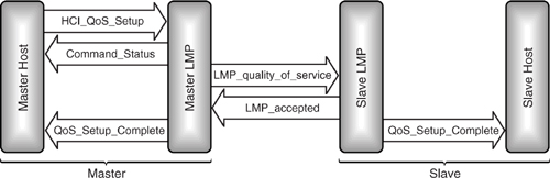
The first message is an HCI_QoS_Setup. Its parameters reflect the parameters of the L2CAP_ConfigReq received by the L2CA layer (see section 17.1.2); they are:
- Connection_Handle—Identifies an ACL connection. This is the connection carrying the L2CA channel being configured.
- Flags—Reserved.
- Service_Type—One of: no traffic, best effort, or guaranteed.
- Token_Rate—In bytes per second.
- Peak_Bandwidth—In bytes per second.
- Latency—In microseconds.
- Delay_Variation—In microseconds.
For a Slave, this command triggers an LMP request to the Master to provide the Slave with the specified QOS. For a Master device, this command triggers a request to the Slave to accept the specified QOS.
17.1.4 LMP QOS Negotiation
LMP commands can be used to configure the poll interval and NBC. The poll interval is the maximum interval between packets sent from Master to Slave. NBC is the number of times a broadcast packet will be repeated (because broadcast packets are not acknowledged, they must be repeated to ensure that they have been received).
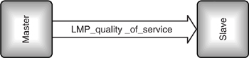
The LMP QOS request can be used to request a new poll interval and NBC. If the Master sends LMP_quality_of_service, the Slave cannot reject the new QOS so there is no need for an LMP_accepted message. This is shown in Figure 17–4.
Figure 17–4 LMP message sequence chart for QOS request from Master.
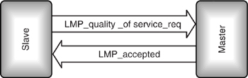
In contrast, Figure 17–5 shows an LMP_quality_of_service_req which can be rejected, so this message requires an LMP_accepted (or LMP_not_accepted) response.
Figure 17–5 LMP message sequence chart for QOS request from Slave.
17.1.5 QOS Setup Completion
The HCI_QoS_Setup_Complete event is generated when LMP has finished setting up QOS. The HCI_QoS_Setup event contains a status field. If the setup succeeded (an LMP_accepted was received), then this is set to zero to indicate success; if the setup failed (an LMP_not_accepted was received), then the status field will indicate an error. For instance, the value 0x0d indicates that the host at the other end of the link terminated the connection, due to low resources. This could also be used to indicate that the remote host would not accept the QOS parameters requested. (In fact, the host has not completely rejected the connection and LMP can try again with different QOS parameters; while slightly inaccurate, this is the error message that best reflects the situation).
If HCI_QoS_Setup indicates that QOS setup failed, then the L2CA layer must send a L2CAP_ConfigRsp with Result = Configuration Failed. The L2CA which sent the original L2CAP_ConfigReq can then signal to the higher layer application which requested the QOS that it is unavailable by sending an L2CA_ConfigRspNeg. The application must then decide whether to try again with a less demanding QOS, or to give up. At this stage, a decision could also be made to shut down some connections or services so that the desired QOS could be achieved. The Bluetooth specification does not specify how the higher layers should handle failure to achieve the desired QOS, this is left up to the implementers of the higher layer applications, services, or protocols.
If HCI_QOS_Setup indicates that QOS setup suceeeded, then the L2CA layer must send a L2CAP_ConfigRsp with Result = Success. The L2CA which sent the original L2CAP_ConfigReq can then signal to the higher layer application which requested the QOS that it is available by sending an L2CA_ConfigRsp. If this was the last configuration request on the L2CA channel, the channel will then move to the open state and be available for transferring data at the desired QOS.
17.2 QOS Violations
Once a channel has been configured for a particular QOS, it is possible that interference or system errors may stop that QOS from being achieved. It is important that applications are aware if their QOS is not as requested, as they may wish to shut down the link rather than run it at an inappropriate quality, or the user may wish to shut down other links to improve the quality available on this link.
The link manager attempts to empty its transmit buffers at the rate specified by the QOS parameters to which it has agreed. If the transmit buffers overflow LM reacts by sending a QOS violation event to the L2CA layer. Even if the service type is best effort, unless L2CA said it didn’t care about token rate, a QOS violation event should be reported. In systems with an HCI, the QOS violation event is sent as an HCI_QOS_Violation event.
When the L2CA layer receives the QOS violation event, it calls an L2CA_QoSViolationInd callback to indicate to the higher layer application protocol or service using the connection that the requested service is not being provided. This provides an opportunity for the higher layer to decide whether it wants to reconfigure the connection or take some other action.
17.3 Flushing And Delays
The link manager will attempt to enforce delay variance by setting the polling interval for each connection. This ensures that packets are transmitted regularly on all connections. However, sometimes a connection is subject to interference and packets just can’t get through. Old data will accumulate in the stack, while the baseband tries again and again to transmit the same packet. On systems with an HCI, when the lower layers of the stack run out of buffers, the host will be flow controlled and the lower layers will continue trying to resend the same old data while the host is prevented from sending new data.
This is a good system where it is vital that every packet gets through. For example, if a file is being transferred across an ACL link, it is important for every byte to get through correctly. However, on some types of links, it is more important that fresh data is sent. For example, some video compression systems can handle a missing packet by freezing the picture, and if such a system is being used, it is more important to show up to date information than to make sure that every last byte gets through.
For systems where it is important for data to be fresh and not so important for every byte to get through, the Bluetooth specification provides flush commands at the HCI. If the host sends an HCI_Flush command, all data currently waiting for transmission on a link is thrown away. This might mean that the first part of an L2CAP packet is thrown away, so if data transmission started again immediately after an HCI_Flush, the far end of the link could be sent part of an L2CAP packet. Such a fragment of an L2CAP packet would have to be discarded by the receiving L2CA layer, so there is really no point in sending it. Instead, the host controller just discards any data packets it receives for the flushed link until it sees the start of the next L2CAP packet. Once the start of the next L2CAP packet is seen, data transmission begins again as normal. When the flush has finished, an HCI_Command_Complete is returned to tell the host that data transmission is restarting.
Because each ACL link goes to a different device, it is possible for one link to need flushing, while other links are perfectly okay. So, the HCI_Flush command takes a Connection_Handle, which allows the host to specify which link it wants to flush old data from.
Some applications will want to flush whenever data gets beyond a certain age. On poor links, this could lead to many HCI_Flush commands being sent. To save on the number of messages being sent up and down the stack, the Bluetooth specification provides a facility for automatically flushing data once it gets beyond a preset age. The higher layers decide upon a timeout, which governs how long the baseband will spend trying to send an L2CAP packet. A timer is started when the first fragment of each L2CAP packet is sent. If the whole packet hasn’t been sent by the time the timer has expired, then the packet is flushed. The flush timeout is set by the host using the HCI_Write_Automatic_Flush_Timeout command. Like the HCI_Flush command, this command has a Connection_Handle parameter to specify which ACL link it applies to, and of course, it also has a parameter Flush_Timeout, specifying the length of the timer. The timer is specified in units of 625μS (the length of a Bluetooth slot). If the timeout is set to zero, this doesn’t mean flush a packet before it has been sent, it means don’t flush any packets on that link, that is to say, switch off automatic flushing.
The value of the timer can be checked with an HCI_Read_Automatic_Flush_Timeout command.
An HCI_Flush_Occurred event is generated each time a flush occurs. This event is generated whether the flush occurred because of an HCI_Flush command, or because of an automatic flush.
17.3.1 Failed Contact Counter
The failed contact counter measures the number of times in a row an automatic flush happens. Although the counter is returned in a 2 byte parameter, only 12 bits of it are used, so its range is from 0 to 0x0FFF. When a host sends an HCI_Read_Failed_Contact_Counter command, the counter’s value is returned in an HCI_Command_Complete event.
The failed contact counter increments each time an automatic flush happens. The counter is reset to zero when a new connection is established, and when an L2CAP packet is acknowledged for the connection. The counter can also be reset to zero by the HCI_Reset_Failed_Contact_Counter command. This means that the counter will only be nonzero while a series of automatic flush events are happening.
Figure 17–6 shows how the value of the failed contact counter changes as a series of flush events happens.
Figure 17–6 Automatic flushing and failed contact counter.

17.4 Link Supervision
If enough flushes occur in a row, it is possible that the link is incapable of use: maybe the device at the other end has moved out of range, or perhaps it has even been switched off. If this happens, a link supervision timer will elapse and allow the link to be shut down, so that its active member address (AM_ADDR) can be reused.
A separate link supervision timer, Tsupervision, is kept for each link. Each link supervision timer is reset whenever a packet which passes its Header Error Check (HEC) and has the correct AM_ADDR is received on a link. The supervision timer begins counting from a value, supervisionTO. The default value is 20 s, but it can be changed using an HCI_Write_Link_Supervision_Timeout command; possible values range from 0.625 s to 40.9 s. The current value of supervisionTO can be checked with the command HCI_Read_Link_Supervision_Timeout. Since the timer can be set differently on each connection, this command takes a Connection_Handle parameter.
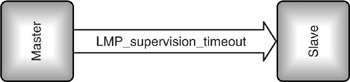
The Master determines how often the Slaves will be contacted, so the Master determines the link supervision timeout. It then communicates the timeout to Slaves by sending an LMP_supervision_timeout command to the Slave’s link manager as shown in Figure 17–7.
Figure 17–7 Message sequence chart for LMP_supervision_timeout.
The value of the supervision timeout should be set to be longer than any hold or sniff periods which are in force on the link. Parked Slaves can be unparked and reparked before the timer elapses, or the timer can be switched off.
17.5 Broadcast Channel Reliability
When a packet is unicast (sent point to point), the Master transmits and the Slave replies. The Slave’s reply carries an Acknowledge (ARQN) bit in the packet’s header which lets the Master know whether or not its transmission was received correctly. When a packet is broadcast, it is sent to many Slaves. There is no reply because if all Slaves replied at once, their transmissions would interfere with each other and no data would get through.
Because Slaves cannot acknowledge receipt of broadcast packets, the Master doesn’t know when broadcast packets have been received, and when they were wiped out by radio interference, so the Master doesn’t know when it needs to retransmit packets. To make the broadcast link reasonably reliable, the Master can transmit each broadcast packet several times. This gives a reasonable chance that one of the broadcast transmissions will get through.
Figure 17–8 shows the difference between broadcast and unicast transmission:
Figure 17–8 Broadcast repetition.
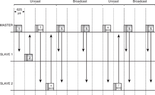
- Packet 1 is a unicast from the Master to Slave 1.
- Packet 2 carries the Slaves reply, including an acknowledge bit to tell the Master the packet got through intact.
- Packet 3 is a SCO packet to Slave 2.
- Packet 4 is the Slave’s reply. SCO packets are never retransmitted, so even though they carry the standard header including the ARQN bit, it is not used for retransmission.
- Packet 5 is a broadcast packet sent by the Master to both Slaves. Neither Slave replies, so this packet it re-transmitted several times to make sure it gets through.
- Packets 6 and 7 are SCO packets. Since these must go out regularly in reserved slots, they interrupt the broadcast repetitions.
Because Slaves only transmit on ACL links when they are addressed by the Master, only the Master is allowed to broadcast on an ACL link.
The more times the Master retransmits, the more reliable the broadcast will be. On the other hand, the more times the Master retransmits, the more bandwidth will be used up, so the data rate will go down. The number of broadcast repetitions must be set to give a tradeoff between data rate and reliability.
For systems with an HCI, the HCI_Write_Num_Broadcast_Retransmissions command sets the number of times the Master transmits each broadcast packet to be sent by the host. The command has a single parameter: the number of retransmissions. The default number of retransmissions is one, that is to say each broadcast packet is sent twice (one transmission plus one retransmission). The HCI_Read_Num_Broadcast_Retransmissions command can be used to check the current broadcast retransmission setting.
The number of broadcast retransmissions should be adjusted as the quality of the link can be expected to vary for many reasons: the distance mobile devices can vary affecting signal strength; objects can get in the way of the link and absorb power; and sources of radio interference can reduce the channel quality.
17.5.1 Channel Quality Monitoring
The host should adjust parameters such as broadcast retransmission according to the quality of the link. To do this, it has to get information on the link quality. The HCI provides the HCI_Get_Link_Quality command to aid in monitoring link quality.
The HCI_Get_Link_Quality command retrieves a value of link quality for a specified connection (the connection is identified by a Connection_Handle parameter). The link quality value is a number between 0 and 255; how it is calculated is up to each implementation to decide, though all implementations have higher numbers indicating higher quality links. This value could be used to reflect a Bit Error Rate (BER) on the link.
17.6 Data Rates And Packet Types
The Bluetooth specification provides a variety of packets for carrying data. Usually DM and DH packets will be used on ACL links. DM stands for Data Medium rate and DH stands for Data High rate. The DH packets achieve a higher rate by using less error correction in the packet; this leaves more room for data. Naturally, the single-slot packets DM1 and DH1 carry less data than the 3-slot packets DM3 and DH3, and the 5 slot packets DM5 and DH5 have the maximum capacity for payload data. Table 17–1 shows the difference in capacity of the different packet types.
Table 17–1 DM and DH Packets
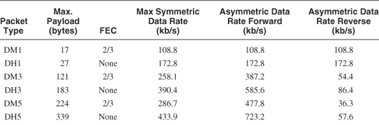
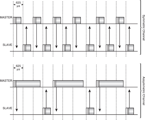
Table 17–1 gives figures for symmetric, asymmetric forward, and asymmetric reverse channels. A symmetric channel uses the same packet types in both directions. This channel type would be used when both Master and Slave needed to send data at about the same rate. Often data will need to be transferred faster in one direction than in the other; for example, if a PDA is browsing the Web via a server, there will be a high data rate from the server to the PDA as Web pages are downloaded, but in the reverse direction, only a few bytes of data will need to be transferred to specify the next link to browse. For such situations, Bluetooth provides asymmetric channels: a large packet size is used in the forward (high data rate) direction, and a small packet size is used in the reverse (low data rate) direction. Figure 17–9 shows a symmetric channel with single-slot packets in both directions, an asymmetric channel with the Master sending 3 slot packets, and the Slave sending single slot packets. Asymmetric channels can be configured so that the Master or the Slave transmits at the higher rate.
Figure 17–9 Symmetric and asymmetric channels.
Asymmetric channels can give higher data rates in the forward direction, but the data rates given in Table 17–1 are for the maximum number of bytes of data which can be transferred on air. When calculating data rates for applications, it should be kept in mind that packet sizes will affect how efficiently packets are transferred. This can mean that asymmetric channels may not be appropriate. Also, higher protocol layers such as L2CAP and RFCOMM will use some of the channel’s capacity with headers and framing information.
For example, if we assume that a regular stream of 20 byte packets is sent via RFCOMM, L2CAP, and HCI, this is what will happen:
RFCOMM adds a byte of address, a byte of control, a byte of length indicator, and a byte of Frame Check Sequence (FCS). (See Chapter 10 for more details.) These extra four bytes mean that L2CAP receives a 24 byte packet. (In fact, RFCOMM escapes some characters, so the data rate could be worse, depending on the data patterns sent.)
L2CAP adds two bytes of length and two bytes of channel ID onto the packet. (See Chapter 10 for more details.) These extra four bytes mean that HCI receives a 28 byte packet.
If the link is using DH1 packets, the payload is 27 bytes, so the L2CAP packet will have to be split up into two DH1 packets.
A DH1 packet can be transmitted at most once every slot pair, which is once every 1350 μS, so 800 packets can be sent each second. Each packet could carry 27 bytes, giving a maximum data rate of 21.6 Kbyte/s, or 172.8 Kbits/s; but in practice, each pair of packets is carrying 28 bytes, giving a data rate on air of 112.2 Kbyte/s, or 89.6 Kbits/s. The data rate is down by almost half at 52%.
400 packets of 20 bytes each can be sent per second to RFCOMM, so above RFCOMM, the data rate is only 8 Kbyte/s, or 64 Kbit/s. Now the data rate is down by 37% of the maximum on air rate.
If we repeat the calculations and see what transfer rates are achieved above RFCOMM for 20 byte packets, we get the figures in Table 17–2. As the packet sizes increase, they become a less and less efficient way of transporting the small RFCOMM packets, so instead of data rates increasing, they decrease.
Table 17–2 Data Rates for 20 byte Packet into RFCOMM Compared with Maximum
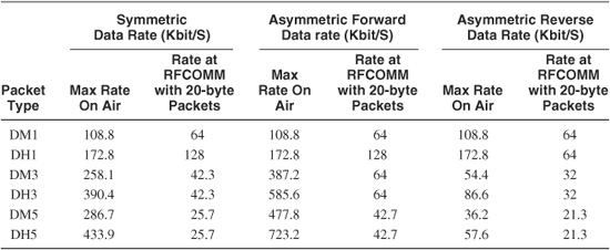
The example above was chosen to make a point and the figures are particularly bad, but it should be kept in mind that figures quoted for Bluetooth channel rates in the specification will not translate to the same data rate at the Application Level.
Another consideration when choosing packet types is the likelihood of corruption. If many packets are being retransmitted, then it is better to use short packets, as these are more likely to get through without errors.
In a real system, losses due to retransmission and signalling packets interfering with data flow will also reduce the data rate.
17.6.1 Channel Quality-Driven Data Rate
The host can change the packet types in use on the link using the HCI_Change_Connection_Packet_Type command. This command has two parameters: a Connection_Handle identifying the connection being configured and a Packet_Type parameter that sets the range of packets which may be used for transferring data on the connection. At least one packet type must be specified.
For ACL connections, the packets are chosen from DM1, DH1, DM3, DH3, DM5, and DH5. Note that the AUX packets are used for test, but are not used for transferring data in normal operation, so they are not among the packet types which can be set by the HCI_Change_Connection_Packet_Type command.
For SCO connections, the packets are chosen from HV1, HV2, and HV3. Note that connections cannot be configured to use DV packets. The baseband specification suggests that the device could automatically use DV packets to transfer data on the SCO link, if data is available to be sent to the same destination as the SCO packet.
If a connection is configured to use both high rate and medium rate packets, there is a choice of higher data rate (DH packets) or better error protection (DM packets). The Bluetooth specification provides a mechanism for devices to automatically switch between DM and DH packet types according to the error rate on the link.
The simplest mechanism would be for each device to monitor the link. If it saw a high BER on the link when it was using DH packets, it could switch to sending DM packets; if it saw a good link when using DM packets, it could switch back to DH packets. However, it is possible for the quality of radio receivers to vary greatly between devices. This could lead to one device seeing few errors on the channel while the other sees a much higher error rate. Therefore, the type of packet transmitted on the link has to be controlled by the quality of the packet at the opposite end of the link, not at the same end; that is to say the Master chooses the Slave’s packet types, and the Slave chooses the Master’s packet types.
To achieve this control, messages have to be sent across the link. The Link Management Protocol is used to do this. To begin using channel-driven QOS, the LMP_auto_rate message is sent, as shown in Figure 17–10. This signals that the device sending the message is willing to let its peer LM choose packet types on the link. If the link manager at the far end of the link decides that it wants to change the packet type, it sends back an LMP_preferred_rate message, which has a single parameter: the data rate, which can be set to high rate (use DH packets) or medium rate (use DM packets).
Figure 17–10 Message sequence chart for channel quality-driven packet type change.
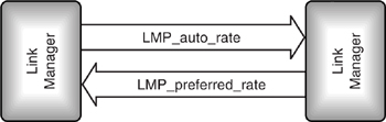
Note that the LMP_preferred_rate message is not used to switch between single slot, 3 slot, and 5 slot packets; it merely chooses whether DH packets or DM packets are used.
To make the choice between packet types, the link manager needs information on the quality of the link. The Forward Error Correction (FEC) and Header Error Correction (HEC) are dealt with by the baseband part of the Bluetooth protocol stack. The baseband also takes care of retransmissions. In order for link manager to choose whether or not to switch between high and medium rate packet types, it must be able to access information from the baseband on how many errors the baseband is correcting and how many packets are being retransmitted.
In some environments, the link quality will fluctuate, with periodic bursts of errors caused by interference, objects blocking the link, or devices moving around. If a device is frequently switching between DH and DM packets, it may use more bandwidth on the messages causing the switch than it saves on using DH packets. Under such circumstances, it would make sense to stay using DM packets, or at least require a low bit error rate to be measured for a while before the switch is made.
The Bluetooth specification does not specify the exact criteria for making the switch between packet types, so it is up to implementers to decide the details of when they will choose to switch rates, both in the data used to make the decision to switch and the levels of errors at which the switch is made.
17.7 Summary
For the Bluetooth specification, getting Quality of Service (QOS) means getting the required data rate, delay variance, and reliability.
The link manager provides QOS capabilities by a variety of means, including choosing packet types, setting polling intervals, allocating buffers, allocating bandwidth to links, and deciding whether to perform scans. Link Managers negotiate peer-to-peer to ensure that QOS is coordinated at both ends of a link.
At the L2CA level, too, QOS is negotiated end-to-end: one L2CA signals its peer to request a QOS; this peer in turn asks its local link manager if it can fulfill the request. On systems with an HCI, this interaction between L2CA and link manager is accomplished through a series of HCI commands and events.
For unicast (point to point), a reliable link is provided by the receiver acknowledging packets. Any packets which are not acknowledged are retransmitted. Broadcast packets are not acknowledged, so to provide a reliable link, a Bluetooth device can be set to retransmit broadcast packets a certain number of times.
Sometimes on point-to-point links, the baseband’s attempts to provide a reliable link can result in data being kept in the stack and retransmitted time and time again while the baseband waits for an acknowledgement. For some applications, old data is not worth sending, so a flushing mechanism can be used to override the reliable link and allow the system to throw away data. This can be done directly with a command, or automatically when a timer elapses.
L2CA and the lower layers of the stack do their best to provide the QOS which higher layer applications and protocols request, but as with any wireless system, there are never any real guarantees, so sometimes the QOS requested can’t be achieved. In such cases, the lower layers tell the higher layers by sending QOS_violation events, so the higher layers of the stack know the required QOS is not being achieved and can decide what to do about it.
If a link’s quality deteriorates, one thing that can be done is changing the packet types in use. These can be set directly through the HCI, or the Link Manager can be set to automatically switch between high-rate packets and medium-rate packets, which have better error protection. If multi-slot packets are in use, then using shorter packets can also help to make a link more reliable, though it should be kept in mind that data rates can suffer if short packets or packets with more error protection are used.
Sometimes a link is lost altogether and no good packets can be received. If this happens a supervision timer will elapse. When this happens, the link is judged to be beyond saving, so it will be reset. Any higher layer applications or services wanting to use the link will have to set it up again from scratch.