
14
The Telephony Control Protocol
Bluetooth’s Telephony Control protocol Specification (TCS) defines how telephone calls should be sent across a Bluetooth link. It gives guidelines for the signalling needed to set up both point to point, and point to multipoint calls. It also provides a way to send DTMF tones across a Bluetooth link. TCS is adapted from ITU-T Recommendation Q.931. Bluetooth also defines a subset of TCS called “lean TCS”.
The acronym used for telephony control does not fit in with the convention used in the rest of the Bluetooth stack. The Link Manager Protocol specification is abbreviated to LMP, the Logical Link Control and Adaptation Protocol specification is abbreviated to L2CAP, but the Telephony Control protocol Specification is abbreviated to TCS. The reason for not following the convention of the rest of Bluetooth is that the acronym TCP is so widely used for the Internet task control protocol that reusing the same acronym would be certain to cause confusion.
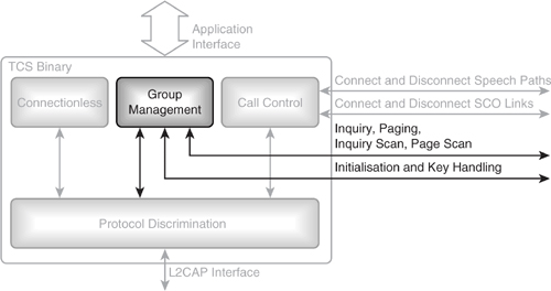
Figure 14–1 shows how TCS fits into the rest of the Bluetooth protocol stack. A hostless system is shown so there is no Host Controller Interface (HCI) layer. If TCS were implemented on a system with HCI, then the HCI layer would sit below L2CAP and above the baseband and Link Manager.
Telephony control relies upon the presence of a speech synchronisation and control system which can be used to set up speech paths through the baseband using SCO links.
Telephony control is split up into four parts:
Figure 14–1 Telephony control protocol stack.
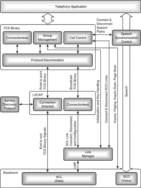
- Call control—Handles connection and disconnection.
- Group management—Handles groups of devices; this part manages inquiry, paging, and scanning, as well as security.
- Connectionless—Handles broadcast information.
- Protocol discrimination—Handles directing messages between the other parts of TCS and L2CAP.
TCS is driven by a telephony application which provides the user interface, and provides the source of voice or data transferred across the connections set up by TCS.
The specification for TCS suggests that multiple calls could be handled by running multiple instances of TCS, each with its own L2CAP channel identifier. The assigned numbers part of the Bluetooth core specification allocates L2CAP protocol service multiplexer numbers for TCS-BIN and for TCS-BIN cordless. The mechanism by which more instances could be identified has not been defined.
14.1 TCS Signalling
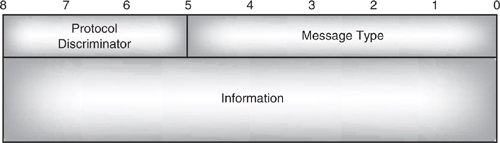
TCS signalling messages are carried in the payload of L2CAP packets. TCS adapts the format used by Q.931, as not all of the information is required. For comparison, Figure 14–2 shows the original Q.931 structure and Figure 14–3 shows the structure used in TCS. Q.931 has extra length fields and also has a call reference value (a handle used to connect a call with a local application which registered the call and which will handle cancellation of the call).
Figure 14–2 Structure of a Q.931 signalling message.
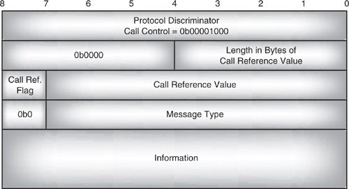
Figure 14–3 Structure of a TCS signalling message.
Note that in Figure 14–2, and elsewhere in this chapter, the least significant bit is on the right. This is the opposite of the convention used in other chapters, but follows the form used in the Q.931 standard and in the TCS part of the Bluetooth specification. Q.931 and TCS use a different convention for bit ordering from most Bluetooth protocols, so care should be taken when interpreting messages that the Endianness is correct.
The three bits of the protocol discriminator field are used to distinguish between Call Control (CC) messages and other TCS messages. It has three possible values:
- 0b000—Call Control (CC) signalling.
- 0b001—Group Management (GM) signalling.
- 0b010—Connectionless (CL) signalling.
The five bits of message type are used to identify which message is being sent. The message types can be divided up into groups: call establishment, call clearing, miscellaneous, group management, and connectionless. The following sections examine the groups of signals and describe how they are used.
14.1.1 Information Elements
The information part of a TCS signalling message is made up of information elements. These can be fixed length or variable length.
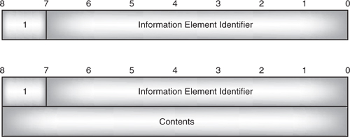
Figure 14–4 shows the two types of fixed length information elements: single byte and two byte elements. Fixed length information elements always have a single bit flag in bit 8 of the first byte, which is set to 1. The remaining seven bits of the first byte carry an information element identifier. For a single byte, fixed length information element, this makes up the whole of the information element.
Double byte information elements have the identifier followed by a byte of content. It is possible to work out from the identifier whether the information element will be one or two bytes.
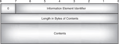
Variable length information elements have the flag bit set to 0. Just like fixed length information elements, they begin with seven bits of information element identifier, which is followed by a single byte length field giving the length of the rest of the information in bytes, and finally the content follows in the rest of the information element. A variable length information element is illustrated in Figure 14–5.
Figure 14–4 Fixed length information elements.
It is possible to have a variable length information element with a length of 0; this is interpreted as if it were absent from the message. Only optional information elements can be sent with the length set to 0.
Most TCS messages have an optional company specific information element. (In fact, only the five messages dealing with DTMF tone generation don’t have an optional company specific information element.) This allows designers to add their own extensions to TCS, but of course, care should be taken when using these because all devices must be able to interoperate with devices which don’t support added in company specific features. The company specific information element includes a company identifier. This is needed so that one company’s commands aren’t confused with another’s. Company identifiers have been allocated for the original promoters group: Ericsson, Nokia Mobile Phones, Intel Corporation, IBM Corporation, and Toshiba Corporation; all other values are reserved. This means that unless more numbers are allocated in future versions of the specification, other companies should not add proprietary extensions to the specification (if they do, they risk these extensions being misinterpreted by other devices, and causing unpredicted effects).
Figure 14–5 Variable length information element.
14.2 Call Establishment Signalling
Call establishment messages (with their type values) are:
- 0b00101—SETUP.
- 0b00110—SETUP ACKNOWLEDGE.
- 0b01010—INFORMATION.
- 0b00100—PROGRESS.
- 0b00000—ALERTING.
- 0b00001—CALL PROCEEDING.
- 0b00010—CONNECT.
- 0b00011—CONNECT ACKNOWLEDGE.
TCS calls can be set up using signalling on a point to point channel or a point to multipoint channel. Point to point would be used when it is known exactly which device the call is intended for. Point to multipoint could be used when a variety of devices might answer the call. For example, a home telephony system might want to send a call alert to every phone in range, whichever phone answers first then takes the call.
Figure 14–6 shows the simpler connection scenario where a call is routed to one known device. First an L2CAP channel is established to the device, then a call request is sent on the L2CAP channel. If the call is accepted, then a speech or data channel is set up between the two devices.
Figure 14–6 Connecting a point to point call.
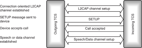
Figure 14–7 Connecting a point to multipoint call.
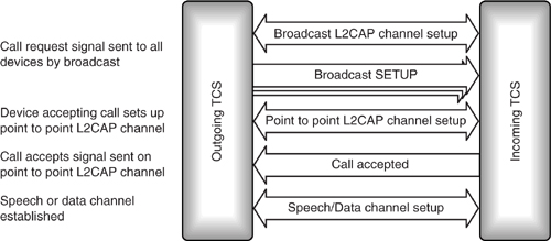
Setting up a call via the broadcast channel is shown in Figure 14–7. It is a little more complex than setting up a point to point call. The signal must be broadcast on the beacon channel. The beacon channel reaches Slaves which are parked, as well as active Slaves. (The broadcast signal may not reach Slaves in Park or Sniff mode.) Only the Master of a piconet may broadcast on the beacon channel, so only the Master may broadcast a call request.
Slaves wishing to accept the call request may not have an active TCS L2CAP signalling channel available. If they do not, then they must set up an L2CAP channel using the Protocol and Service Multiplexer (PSM) number reserved for TCS, which is 0x0005. This will be a point to point link. Once this link has been established, then the device can accept the call on it, and both devices can go on to establish a link for voice or data traffic.
It is possible when a SETUP message is broadcast that several devices will be willing to accept the call, so several devices will answer. For example, a home telephony system could have several handsets all capable of answering incoming phone calls on the same home phone number. TCS only supports point to point calls, so the connection can only be made to one device. The connection will be made to the first device which answers; any other devices which answered the SETUP message but were not assigned the call are sent RELEASE messages to let them know they will not receive a connection.
14.2.1 SETUP Message
The SETUP message carries all the information needed to establish a data or voice connection for a call:
- Call class—Identifies a call as an external call, internal call, service call, or emergency call.
- Sending complete—Sent when the called party number is complete.
- Bearer capability—Gives information on the required capabilities for the link to be used as a TCS bearer channel.
- Signal—Information about whether tones and alerts a handset can generate are switched on or off.
- Calling party number—The number which originated the call.
- Called party information number digits—The number the call is directed to.
- Company specific—This information element can be used to add vendor specific information to any message.
Only the call class is mandatory. The call class is external call for a call connected to a third party on an external network, for example, GSM, ISDN, or PSTN. The call class is internal call for an intercom call, that is to say, a call between two members of a Wireless User Group (see Section 14.5 for more on wireless user groups). The call class is service call for a call which is just used to transfer configuration information. An emergency call is a special class of external call; it has its own call class because emergency calls are often handled differently from normal calls. For example, emergency calls are not charged to the user, and on GSM networks, the SIM card which authorises network access is not needed for emergency calls.
The bearer capability describes the type of link which is needed for the call. It includes the link type (SCO for voice or ACL for data), the packet type (HV1, HV2, HV3, or DV), the voice coding (CVSD, PCM A-law, or PCM μ-law), and the quality of service parameters for the link. If there is no bearer information, then the link type defaults to a SCO link using CVSD coding and HV3 packets.
In Q.931 as in TCS, the signal information element says whether tones and alerts are on or off. Q.931 has values for setting ring, intercept, network congestion, confirm, answer, call waiting, off-hook warning, preemption, and various alerting tones. Bluetooth versions 1.0 and 1.1 have just three possible values: external call, internal call, and call back. TCS has a very limited set of tones compared with the range the Q.931 standard supports, presumably the reasoning behind this is that limiting the range of tones generated will make implementing TCS tone generation simpler. However, it is also possible that this part of the TCS specification needs more work, because it is unclear from the values how a tone is switched on and off. In Q.931, the signal information element has different values when switching a tone on and off, whereas TCS only has one value for each of external call, internal call, and call back.
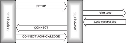
14.2.2 Message Sequences for Establishing a Call
The SETUP message is the first message sent when establishing a call. In lean TCS, it only has to carry a call class to say whether the call is internal, external, service, or emergency.
If lean TCS is not being used and the SETUP message doesn’t have a sending complete information element, the called party number might be incomplete. If an incoming side isn’t using lean TCS and suspects the called party number is incomplete, then it has to try to get some more information. It does this by sending a SETUP acknowledgement message.
The outgoing (calling) side responds with one or more INFORMATION messages. When the incoming side gets a message with a sending complete information element or otherwise works out that it has the whole of the called number, then it sends a CALL PROCEEDING message to the outgoing side, to let that side know that it is processing the call.
Next, the incoming side starts alerting its user; typically this would involve sounding a ring tone or tune to let the user know a call is coming in. The incoming side sends an ALERTING message to let the outgoing side know that the user is being alerted.
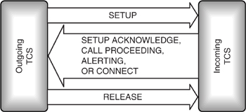
When the user accepts the call (usually by pressing a button), the incoming side tells the outgoing side by sending a CONNECT message. The outgoing side replies with a CONNECT accept message and the call begins. The call setup messages are shown in Figure 14–8.
The SETUP message may carry all the information needed to connect, in which case, the SETUP ACKNOWLEDGE and INFORMATION messages are not needed.
Figure 14–8 Message sequence chart for TCS connection with optional messages.
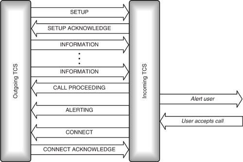
Figure 14–9 Lean TCS message sequence chart for TCS connection.
Also, the incoming side can omit either of the CALL PROCEEDING and ALERTING messages.
Figure 14–9 shows a minimal set of messages to establish a connection. This minimal set would be implemented by a device using lean TCS.
If a SCO link is being used as the bearer for the call, then the SCO link initialisation is started before the CONNECT message is sent. The audio path is connected to the SCO link when the CONNECT or CONNECT ACKNOWLEDGE message is received.
14.2.3 Timeouts
What happens if the call isn’t picked up? Even a normal PSTN phone will not ring forever; eventually the network will decide that nobody is going to answer the call and will disconnect. With Bluetooth devices setting up calls over TCS, there may be no network involved, so the devices have to decide for themselves when to give up trying to connect a call.
To do this, the outgoing device starts a 20 s timer, T303, when it sends the SETUP message. If there is no response to the setup message by the time T303 expires, then the outgoing side gives up on the call. What it does depends upon whether the SETUP message was broadcast or sent to one device.
- If the SETUP message was broadcast, the outgoing side just gives up on the call.
- If the SETUP message was sent point to point to one device, then a RELEASE COMPLETE message is sent to the same device.
The release complete message has a parameter which specifies why the call was released. In this case, the parameter is set to 102, which means “recovery on timer expiry”.
Similarly, a series of other timeouts are used throughout call establishment. These are illustrated in Figure 14–10. There is no timeout defined on the incoming side during the period when the user is being alerted. The assumption is that the application will implement its own timeout and either accept or reject the call.
Figure 14–10 States involved in call establishment.
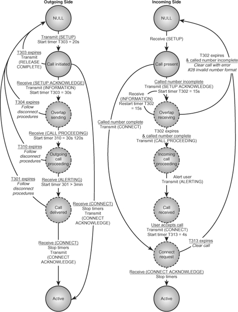
For lean TCS, the outgoing (left) side of the diagram would just have null, call initiated, and active states. The incoming (right) side of the diagram would just have null, call present, and active states.
The optional states are shown with dashed outlines; any of these states can be skipped. For clarity, Figure 14–10 does not show all the possible state transitions when some of the optional states are skipped.
14.3 Call Clearing Signalling
The disconnect procedure uses three call clearing messages:
- 0b00111—DISCONNECT.
- 0b01000—RELEASE.
- 0b01001—RELEASE COMPLETE.
Either the incoming or outgoing side can start a disconnect by disconnecting from the bearer channel and sending a DISCONNECT message. The side receiving the disconnect message also disconnects from the bearer channel and sends a RELEASE message and goes to the null state. When the side which initiated the disconnect receives a RELEASE COMPLETE message, it too goes to the null state. The message exchange to disconnect is shown in Figure 14–11.
The side which transmits the DISCONNECT starts a 30 μs timer, T305, when it sends the DISCONNECT message. If this expires it sends a RELEASE message.
Whenever a RELEASE message is sent, a 4 s timer, T308, is started. If the timer expires before a RELEASE COMPLETE is received, the side which sent the RELEASE returns to the null state. This applies whether the RELEASE was sent because a DISCONNECT was received, or because T305 timed out.
Figure 14–11 Message sequence chart for call clearing.
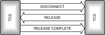
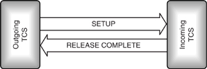
Figure 14–12 Message sequence chart for rejecting a call.
The outgoing side can send in band tones while the call is being cleared. If it wants to do this, it tells the other side by sending the progress indicator message “#8 in-band information or appropriate pattern is now available” in the DISCONNECT signal.
A call can also be cleared by the incoming side rejecting a SETUP message by responding with a RELEASE COMPLETE message, as shown in Figure 14–12.
When a SETUP signal is sent on the broadcast channel, it is possible that more than one device will respond. The outgoing side sends a release message to any device which sends a SETUP ACKNOWLEDGE, CALL PROCEEDING, ALERTING, or CONNECT and which hasn’t been selected for the connection. These messages are sent on the L2CAP channel the device responded on. The messages for call clearing are shown in Figure 14–13.
Because a call is only assigned to one device, it is not possible for multiple devices to join in on a call at the same time. This means that TCS is limited to point to point links; it does not support conference calls among Bluetooth devices in a WUG.
Figure 14–13 Message sequence chart for clearing a call to a multipoint device.
14.4 DTMF Signalling
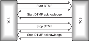
TCS messages can be used to control DTMF (Dual Tone Multiple Frequency) tone generation. DTMF tones are pairs of tones sounded together which are used to send numbers down a phone line. The messages in this category (with their type values) are:
- 0b10000: Start DTMF—Starts a DTMF tone at the far end of a link.
- 0b10001: Start DTMF acknowledge—Confirms that the tone is being sounded.
- 0b10010: Start DTMF reject—Refuses a start DTMF message.
- 0b10011: Stop DTMF—Stops a DTMF tone at the far end of the link.
- 0b10100: Stop DTMF acknowledge—Confirms that the tone has been stopped.
DTMF tones can only be sent while a call is in the active state.
To get a device to generate DTMF tones, it is sent a start DTMF message. The side receiving the message can either reject it with a start DTMF reject message, or begin generating a tone and respond with a start DTMF acknowledge message.
To stop a DTMF tone, a stop DTMF message is sent. This message cannot be rejected, so the DTMF tone generation is always stopped and a stop DTMF acknowledge reply sent.
14.4.1 Register Recall
In register recall, a register in a mobile phone handset is seized by an incoming call so that a value can be entered into the register, or so that some action in the handset can be triggered.
To do this in TCS, an INFORMATION message is sent with a keypad facility information element set to 0x16 = register recall. Once the INFORMATION message has been sent, numbers can be sent as DTMF tones using the DTMF tone control messages as shown in Figure 14–14. In this way, the far end of the link can control a phone handset as if its keypad buttons were being pressed.
Figure 14–14 Message sequence chart for DTMF tone generation.
14.5 Wireless User Group (WUG) Signalling
A Wireless User Group (WUG) is a collection of Bluetooth devices which support TCS. When devices in a WUG are joined in a piconet, the Master of the piconet is also the Master of the WUG. WUG functions are provided by the Group Management (GM) part of TCS (see Figure 14–15).
The Master of a piconet communicates with every device in the piconet, but the Slaves only communicate directly with the Master. So, it makes sense for the Master to act as a coordinator for the WUG by gathering information and distributing it to the Slaves.
The Master coordinates the WUG by telling the members of the WUG which other devices are in the same WUG. The Master also coordinates authentication by telling all the members the parameters they should use for authentication and encryption. Because the Master distributes authentication and encryption information, once a Slave has paired with the WUG Master, it can use the same parameters for any WUG member without pairing again. This means that establishing secure links within a WUG is faster because the pairing step can be skipped.
The GM messages (with their type values) are:
- 0b00110—ACCESS RIGHTS REQUEST.
- 0b00111—ACCESS RIGHTS ACCEPT.
- 0b01000—ACCESS RIGHTS REJECT.
- 0b00000—INFO SUGGEST.
Figure 14–15 TCS group management.
- 0b00001—INFO ACCEPT.
- 0b00010—LISTEN REQUEST.
- 0b00100—LISTEN SUGGEST.
- 0b00011—LISTEN ACCEPT.
- 0b00101—LISTEN REJECT.
ACCESS RIGHTS messages are used when devices join a WUG. INFO messages are used to distribute information needed to connect between WUG members. LISTEN messages are used by WUG members to connect directly to one another, bypassing the WUG Master.
14.5.1 Joining a WUG
For a device to join a WUG as an active member, it must first join the piconet where the Master is the WUG Master. The device joining can stop there and just use the TCS services of the WUG Master, or it can ask for full access rights to the WUG.
To ask for access rights to the WUG, the new device sends an ACCESS RIGHTS REQUEST message to the WUG Master. As shown in Figure 14–16, the Master can choose to accept or reject the new joiner. Every WUG member is given access to security information on all WUG members, so it is important that the WUG Master does not accept the access rights request if it does not trust the joining device.
14.5.2 Configuration Distribution
Unlike normal networks, Bluetooth piconets can frequently change their configuration as devices move in and out of range. This means that the members of a WUG which are visible to the Master can keep changing. The Master needs to be able to tell all the members of the WUG when a WUG member disappears or a new member appears.
Figure 14–16 Message sequence charts for obtaining access rights.
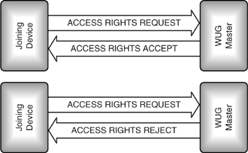
Figure 14–17 Message sequence chart for configuration distribution.
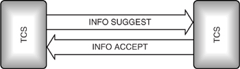
To do this, the Master sends information to all the WUG members it can see using an INFO SUGGEST message. The WUG member replies with an INFO ACCEPT message (Figure 14–17). There is no message for refusing the INFO SUGGEST message, but the WUG members are not forced to store and use the information it contains.
The INFO SUGGEST message carries a configuration data information element. This begins with the standard fields for a variable length information element: the information element identifier (0b00000001), followed by the length of the contents in bytes. Next, the configuration information for each active member of the WUG is listed, starting with the lowest numbered WUG member. The information given is:
- Two bytes of internal number, encoded in IA5 characters.
- Six bytes of Bluetooth address.
- Sixteen bytes of link key for using on the outgoing channel to the WUG member.
Every time the configuration of the WUG changes, all information needed to contact every active member of the WUG is sent.
It may seem insecure to send all the link keys every time the WUG configuration changes, but because all communications within a WUG are encrypted, they are always transmitted in encrypted form. To keep the configuration information as secure as possible, the Master does not broadcast it, instead the Master transmits the INFO SUGGEST message separately to each device on a point to point channel using that device’s link key.
Handing over every single device’s link keys to any new WUG member means that member has access to all the services provided by every other WUG member. This is the reason why the WUG Master is allowed to refuse a new member sending an ACCESS REQUEST to join the WUG.
14.5.3 Fast Intermember Access
There would be no point in handing out information on the link keys of WUG members if they could only communicate through the Master, so not surprisingly, WUGs have facilities for links to be set up directly between members.
A WUG member which wants to talk directly to another WUG member sends a LISTEN REQUEST message to the WUG Master. This message carries the number of the WUG member the sender wants to connect with. The Master forwards a LISTEN SUGGEST message to the WUG member identified by the number in the LISTEN REQUEST message.
The LISTEN SUGGEST message has at most two information elements: one identifying the type of the message and an optional element for company specific information. This means that the WUG member receiving the LISTEN SUGGEST knows another device wants to establish a link with it, but has no idea who the other device is.
If the device receiving the LISTEN SUGGEST is willing to link directly with another WUG member, it replies with a LISTEN ACCEPT containing its clock offset, and the Master forwards this to the device which requested the link.
The message sequences for accepting a LISTEN REQUEST are shown in Figure 14–18.
The clock offset in the LISTEN ACCEPT message has to be an offset from the WUG Master’s clock since this is the clock that all WUG members are synchronised with, and it is their only common point of reference.
The device sending the LISTEN ACCEPT message starts a 2 s timer, T405, and begins page scanning immediately after sending the message. The device which sent the original LISTEN REQUEST receives the LISTEN ACCEPT and immediately uses the clock offset information to start paging the device it wants to connect with.
Setting up a connection between two WUG members in this way is faster than normal paging and page scanning for two reasons. First, the devices can guarantee that their paging and page scanning will be in phase; they don’t have a delay while they wait for a page and page scan to coincide. Second, because the paging device knows the clock offset of the page scanning device, it can predict what frequency it will be scanning on, so it can hop onto that frequency faster than if it were just probing randomly.
It is possible that the LISTEN SUGGEST will be rejected. The two possible sequences for a LISTEN SUGGEST being rejected are shown in Figure 14–19.
The top chart shows the Master rejecting the message. This can happen for three reasons. First, it can occur when the WUG member uses a called party number which doesn’t match any of the devices in the WUG. In this case, the Master replies with a LISTEN REJECT message containing the error code “#1 unallocated (unassigned) number”. Second, the Master can reject when the called number is valid but the device isn’t answering (probably because it moved out of the range of the Master). In this case, the Master replies with a LISTEN REJECT message containing the error code “#20, Subscriber absent”. The third possible reason for rejecting is when the called party number belongs to a WUG member which is already involved in an external call via the WUG Master. In this case, the Master replies with a LISTEN REJECT message containing the error code “#17, User busy”.
Figure 14–18 Message sequence chart for fast intermember access.
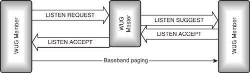
Figure 14–19 Message sequence charts for rejecting fast intermember access.
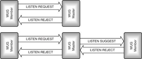
The lower chart shows the second WUG member rejecting the connection. The user is only allowed to reject the call if it is already involved in an internal call within the WUG. In this case, the call is rejected with a LISTEN REJECT message containing the error code “#17, User busy”.
14.6 Connectionless Signalling
There is just one connectionless message:
- 0b00000—CL INFO.
The CL INFO message can carry audio control information and vendor specific information. It does not apply to a specific channel.
The audio control information element can be used to increase or decrease volume and microphone gain.
When TCS signalling messages are sent on the connectionless (broadcast) channel, the Master must switch from using the usual semi-permanent link keys to using KMaster, the broadcast link keys. For more details on security on the broadcast link, see Chapter 15.
14.7 TCS Call States
TCS uses the user side of Q.931, however this is still quite complex, so a subset of Q.931 states has been defined called “lean TCS”. Figure 14–20 shows the state transition diagram for lean TCS.
There are five general states which can apply to both incoming and outgoing sides:
- Null—No call is present.
- Active—A call has been allocated to a particular device, and channels have been set up.
- Disconnect Request—A request to disconnect has been sent, but no response has been received.
- Disconnect Indication—The network (outgoing) side has disconnected, so the incoming side has been invited to disconnect.
- Release request.
Figure 14–20 State transition diagram for lean TCS.
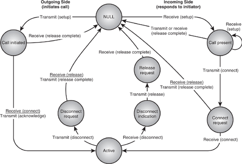
The outgoing side can also be in the call initiated state. The incoming side can also be in the call present or connect request state.
TCS allows for the implementation of more states to cover the complete Q.931, but only the lean TCS states are mandatory. Lean TCS has been defined because many hand-held Bluetooth devices will have limited computing resources, so lean TCS allows a simpler implementation, saving on memory and processing.
14.8 Summary
TCS provides call control signalling to establish voice and data calls between Bluetooth devices. These can be used to direct calls from an external network to other Bluetooth devices. For instance, a cellular phone could receive a call and use TCS to redirect the call to a laptop, allowing the laptop to be used as a hands-free phone.
TCS signals are sent on an L2CAP channel with a Protocol and Service Multiplexor (PSM) reserved for TCS. A separate bearer channel is established to carry the call; this can be a SCO channel or an ACL channel. Once TCS calls have been established, DTMF tones can be sent on the TCS signalling channel.
TCS can be used to join devices in a Wireless User Group (WUG). A piconet Master acts as the WUG Master and handles pairing to all devices which join the WUG. The WUG Master distributes information on WUG members throughout the WUG. Devices in a WUG can request connections directly to one another, allowing calls to be set up faster than if they were not in the WUG.
TCS does not define handover of calls from one device to another, and does not provide a mechanism for groups of devices to enter into conference calls; only point to point links are supported.