
15
Encryption and Security
Cable based communication is inherently secure. However, since anyone could potentially listen into a wireless transmission, security is a key issue for wireless communications systems.
Security is dealt with at many levels in the Bluetooth specification:
- The baseband specification details the SAFER+ algorithms used for security procedures.
- The Link Manager specification covers link level procedures for configuring security.
- The HCI specification details how a host controls security and how security-related events are reported by a Bluetooth module to its host.
- The Generic Access Profile covers security modes and user-level procedures for use in all products implementing Bluetooth profiles.
- There is also a Bluetooth SIG white paper on the security architecture, which suggests a framework for implementing security and gives examples of how services might use security.
The Bluetooth specification uses a variant of the SAFER+ cipher to authenticate devices (to ensure they are who they claim to be). Designed by Cylink Corporation as a candidate for the U.S. Advanced Encryption Standard (AES), it has since been released into the public domain.
The encryption engine must be initialised with a random number. After initialisation, the encryption engine needs four inputs:
- A number to be encrypted or decrypted (this is the data being passed between devices).
- The Master’s Bluetooth device address.
- The Master’s Bluetooth slot clock (clock bits 26-1; bit 0, which measures half slots, isn’t used).
- A secret key which is shared by both devices.
All devices in a piconet know the Master’s Bluetooth device address and slot clock. The secret key used for encryption varies. Sometimes a device wants to verify that it shares a secret key with another device that claims to share the key. The verifier can’t just ask the claimant to transmit the key because anybody could eavesdrop on it. Instead, the verifier sends a random number and gets the claimant to encrypt the number using the secret key and return the encrypted version. The verifier can encrypt the random number using the secret key, and compare its result with the claimant’s result. If they match, then both sides must have had the same secret key. This exchange of messages is shown in Figure 15–1.
Figure 15–1 Authentication using the Bluetooth encryption engine.
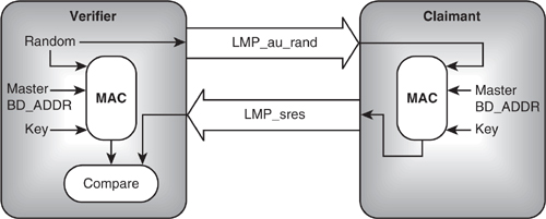
The full exchange of messages to authenticate a device is slightly more complicated than this, as both devices’ encryption engines must first have been initialised with the same random number.
15.1 Key Generation And The Encryption Engine
The cipher algorithm adopted by the Bluetooth SIG for authentication and encryption is a variant of a strong contemporary algorithm available in the public domain. SAFER+ (Secure And Fast Encryption Routine) is the latest in a family of 64 bit block ciphers developed by the Swiss Federal Institute of Technology and Cylink Corporation in the United States since 1993. SAFER+ generates 128 bit cipher keys from a 128 bit plaintext input.
In 1998, SAFER+ was submitted as a candidate successor to the Data Encryption Standard (DES)—referred to as the Advanced Encryption Standard (AES)—in the United States.
During the AES candidate testing phase in 1999, SAFER+ was found by the U.S. National Institute of Standards and Technology (NIST) to have a good security margin with only some minor security gaps. In fact, these do not affect the 128 bit version of the algorithm used in Bluetooth anyway. However, it was not accepted into the second round due to its relatively slow speed when compared with the other candidates, especially for 32 and 64 bit microprocessor-based implementations.
More details on the SAFER+ algorithm are available in1 or on the NIST Web site at http://www.nist.gov/aes.
1Prof. J.L. Massey, Prof. G.H. Khachatrian, Dr. M.K. Kuregian, SAFER+ Candidate Algorithm for AES—Submission Document, Cylink Corp, June 1998.
In Bluetooth, the plaintext is provided by a combination of a predefined device PIN number or a unit key and random number. The resulting key is then loaded together with the BD address, Master clock bits, and another 128 bit random number into a bank of Linear Feedback Shift Registers (LFSRs). The output of these LFSRs is combined by a Finite State Machine (FSM) called the “Summation Combiner” to produce a cipher stream which is then exclusive-OR’d (XOR’d) with either the transmit or receive data streams as required.
The LFSR block and Summation Combiner are together referred to as the “Encryption Engine” and this process as the “E0” algorithm. This is the part that actually encrypts or decrypts the data bitstream, while the key generator is the part that uses the SAFER+ algorithm to generate the keys used by E0.
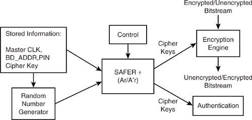
The diagram in Figure 15–2 illustrates the functional structure of the authentication and encryption procedures. During initialisation, a device specific PIN number is used to generate a 128 bit key using the BD_ADDR of the claimant and a random number shared by the claimant and verifier. The authentication procedure ensures that both units are using the same 128 bit key, and therefore that the same PIN number was entered into both units. This key (Kinit) is used to create a new 128 bit key, shared between two units (Kcombo) by the key generator which includes the current key, a new random number from each unit, and each unit’s BD_ADDR. This new key is a link key and is used with the BD_ADDR and the results of the authenticate routine to produce an encryption key Kc. This encryption key may be shortened to K' c due to national security export restrictions in some countries. The encryption key is then used with the Bluetooth clock value and the BD_ADDR to initialise the Encryption Engine, which produces the cipher stream. This cipher stream is then used to both cipher and decipher the bitstream data.
Figure 15–2 Encryption and authentication block diagram.
There are three main operations that need to be performed:
- Random number generation—This may be carried out in hardware or software.
- Key generation—Based on the SAFER + algorithm, this is a slow process, typically involving hardware and software elements. Since key generation is not performed frequently and then only during the lengthy LMP negotiation procedures, it is not time critical.
- Encryption—Engine initialisation and cipher stream generation use precalculated encryption keys and address/clock information, but the stream generation occurs in real time and is thus typically implemented in hardware.
15.1.1 Encryption Keys
There are a number of different keys used in Bluetooth, and these can be divided into three main types: link keys, sub-keys, and the resulting encryption keys. Each key is generated using one of a set of five different “E” algorithms, and with the exception of E0, they are all based on the SAFER+ algorithm.
15.1.1.1 Link Key: K. Link keys are used as authentication keys between Blue-tooth devices and to generate encryption keys. There are various types of link keys, each is generated in a different way. Link keys are 128 bit numbers generated using “E” implementations of the SAFER+ algorithm. They are used for all security transactions. Link keys can be either semipermanent (used for many sessions) or temporary (used during a current session only). Whenever a new link key is generated, it is verified by mutial authentication.
15.1.1.2 Master Key: Kmaster. This type of key is for point to multipoint communications and may replace for a time the current link key. This key is generated using an E22 implementation of the SAFER+ algorithm and is temporary.
15.1.1.3 Unit Key: e.g., KA. This semipermanent key is generated in every single unit often only once during factory setup. While it is unlikely, the unit key might be changed at any time.
15.1.1.4 Combination Key: KAB. Changing the unit key is undesirable since in some systems, many units may wish to use the same unit key as link key. A combination key is dependent on two units; each unit produces and sends a random number to the other. A new 128 bit combination key is derived using SAFER+ for each new combination. A combination key replace is often used to replace the unit key for a period and while they are generated in a different way, they are functionally indistinguishable. A combination key is often created toward the end of unit pairing.
15.1.1.5 Initialisation Key: Kinit. The 128 bit initialisation key is a link key used for a single session and is created each time the unit is initialised. The initialisation key is only used when no combination keys or unit keys have been exchanged yet. The key is generated using an E22 implementation of SAFER+ and uses the PIN number. An initialisation key is often created toward the beginning of unit pairing.
15.1.1.6 Encryption Key: Kc. This key is derived from the current link key, but may be shortened due to national security export restrictions in some countries. The full-length key is derived with the E3 SAFER+ algorithm. The Encryption Engine, E0, uses this key to produce the cipher stream.
15.1.2 The E Algorithms
E0—Cipher stream generation / Encryption Engine.
E0 creates and applies the cipher stream to the bitstream data.
First the block of LFSRs is loaded with the BD address, Master clock bits, and 128 bit random number in an appropriate order. The outputs of these LFSRs are combined by a Finite State Machine (FSM) called the “Summation Combiner” to produce a cipher stream. This is then exclusive-OR’d (XOR’d) with either the transmit or receive data streams as required. The Bluetooth clock, CLK[26:1], is of course incremented on each slot and since E0 is reinitialised at the start of each new packet, a new cipher stream will be created for each packet.
- E1—Authentication. Here, both Ar and A'r are used to encrypt and validate the E2-generated keys used in the authentication process.
- E2—Authentication key generation. E2 creates the keys which are to be used by the E1 authentication algorithm. Two modes of operation are used depending on the key to be generated:
- E21—Uses a 48 bit BD address to create unit keys and combination keys.
- E22—Uses a user-supplied PIN to create initialisation keys and the master key
- E3—Encryption key generation. E3 is the algorithm that generates the ciphering key, Kc, used by E0. E3 is based on A'r, the modified SAFER+ algorithm.
All SAFER+ based algorithms—that is E1, E2x, and E3—take a 128 bit input and return a 128 bit key. However, to comply with certain national security export restrictions, E0 includes a key length reduction mechanism, which ensures that the LFSRs are loaded with a key of the permissible effective length.
15.1.3 Key Generation and SAFER+
The original SAFER+ algorithm uses a fixed block size of 128 bits, with key lengths of 128, 192, or 256 bits. For Bluetooth, the key length is between 1 and 16 octets, so a Blue-tooth key is between 8 and 128 bits. If a key length shorter than 128 bits has been selected, then the key length used for encryption is reduced by a modulo operation. The reduced key is encoded with a block code; this is done to more uniformly distribute the starting states of the encryption sequence.
The SAFER+ algorithm processes the 128 bit input as 16 octets. The algorithm is broken down into 8 rounds, where all 16 octets are processed bit serially in parallel.
For each round, two sub-keys are combined with the new input data. One sub-key is applied to the input data, while the other is applied to the data after the substitution stage. In both cases, the sub-key elements are added both bitwise and octetwise. After the last round, a seventeenth sub-key is also applied, this time to the result data. Each of the sub-keys is created from the input word according to a schedule, which is dictated by the “Bias Words”. This serves to randomise the sub-keys produced.
Each round consists of two “substitution” functions: one that implements an exponential function and one that implements a logarithmic function. These introduce the desired nonlinearity.
An Invertible Linear Transform (ILT) is then imposed in the form of a Pseudo Hadamard Transformation (PHT), followed by an Armenian Shuffle (AS) bitwise interleaving function. These two operations are carried out three times with a final PHT phase at the end. The PHT function consists of multiple accumulates and bit shifting operations.
The seventeen sub-keys are generated from the 128 bit input to the algorithm. The Sub-Key Generation (SKG) process involves creating a parity word, rotating each of the octet bits, and rotating the octets. The result is then added mod256 to a precalculated bias word.
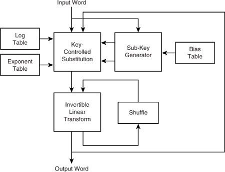
The block diagram in Figure 15–3 depicts the basic structure of the algorithm. Look-up tables are shown for the log, exponent, and bias functions, which is the most likely implementation, though the actual function could of course be used if appropriate.
Figure 15–3 SAFER+ functional block diagram.
15.1.3.1 Ar and A'r. The SAFER+ algorithm is referred to as Ar in the Blue-tooth standard. However, as such, it is only used as part of the authentication procedure. The A'r algorithm is used at least once in almost all key generation procedures and is a modified version of the SAFER+ algorithm where the input to Round 1 is fed back into the algorithm during Round 3. This makes A'r noninvertible and of course unsuitable for use as an encryption algorithm.
15.1.3.2 Advantages of SAFER+ and Associated Implementation Issues. In cryptographic terms, SAFER+ is a relatively simple algorithm, yet it provides a high level of security. Its designers claim that it has no weak keys, is robust against both linear and differential cryptanalyses, and its transparency (that is, its use of only well defined mathematical functions) makes it clear that there are no so-called “trap doors” allowing third party deciphering. The minor security gaps mentioned above were uncovered using differential cryptoanalysis and affect the 192 and 256 bit versions of SAFER+. The 128 bit version as used in Bluetooth diffuses the full key into the algorithm very quickly and so is robust to such attacks. In addition, regular link key changes will further prevent the viability of a cryptoanalysis attack.
Its regular structure and byte orientation make the algorithm suitable for implementation in silicon and small footprint microprocessors (i.e., 8 bit), while also being highly optimisable for modern high performance DSPs or 32 bit microprocessors. A silicon implementation of the SAFER+ algorithm can compute a 128 bit key in less than 100 μs when clocked at 20 MHz.
The following sections explain how the SAFER+ encryption engine can be used to support a variety of security features.
15.2 Secret Keys And Pins
To use encryption, Master and Slave must share the same secret key. This secret key is never transmitted on air. The secret key could be built in by manufacturers (a fixed key), or it could be derived from a Personal Identification Number (PIN) entered through a user interface (a variable key).
An example of a device which could sensibly use fixed keys is a headset for a cellular phone. These could be sold with fixed keys, so that they would not need a costly and bulky user interface to enter security information. To ensure that both ends of the link share the same keys, the user could enter the headset’s information into a cellular handset (these already have an interface suitable for entering numbers, so, unlike the headset, a facility to enter PINs would not add to the cost of the device).
An example of an application where PINs might need to be altered frequently is a hotel or conference center offering Bluetooth LAN access points. When a guest checked in, he or she could be given a PIN number which would allow use of encryption on data sent to the LAN access points.
If a device is to have variable PINs, then naturally the user interface must support entering new PINs. So for devices with an HCI, it is the host (which owns the user interface) that determines whether the PIN is fixed or variable. The HCI_Write_PIN_Type command is used by the host to tell the Bluetooth device whether the PIN is fixed or variable. (The HCI_Read_PIN_Type command can be used to check whether the lower layers believe a fixed or variable PIN is in use.)
When a Bluetooth device needs to query the host for a PIN, it can send the event HCI_PIN_Code_Request_Event. If the host can supply a PIN, it replies with the command HCI_PIN_Code_Request_Reply, which contains the PIN in its parameter list. If the host has no PIN to supply, it responds with the command HCI_PIN_Code_Negative_Request_Reply, which will cause attempts at using security features to fail.
15.2.1 The Bluetooth Passkey
The Generic Access Profile defines the terms used by a Bluetooth device’s user interface. HCI and LMP use the term “PIN,” but the Generic Access Profile requires the user interface to use the term “Bluetooth passkey”.
The PIN used by the baseband can be up to 128 bits (16 bytes). PINs can be entered as decimal digits, or optionally they may be entered as alphanumeric characters. Unicode UTF-8 coding is used to transform the characters into digits.
Because some devices which allow PINs to be entered will not support alphanumeric entry, devices sold with fixed PINs should be sold with a note of the PIN given as decimal digits.
The Logical Link Control and Adaptation Layer (L2CA) needs to be aware that entering PINs through a user interface may take some time. L2CA has a timeout on a response (RTX). The RTX timer’s value is implementation dependent, but it is initially set between 1 and 60 seconds. If the timer elapses while waiting for PIN entry, the timed out request will be resent with the timeout doubled. This continues until the requester decides to abandon configuration. To avoid this timing out, a device which knows it will take some time should send a connection pending response to its peer. This indicates that some processing is happening which may take some time and causes an Extended Response Timer (ERTX) to be started in place of the RTX timer, thus giving sufficient time for the PIN to be entered. ERTX is again implementation dependent, but its value is initially between 1 minute and 5 minutes, so it allows much more time for the user to enter a PIN.
15.3 Pairing And Bonding
The Generic Access Profile calls two devices that know they share a link key bonded. The procedures involved in creating a relationship based on a common link key is called bonding.
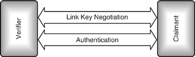
Bonding involves creating a link specifically for the purpose of creating and exchanging a common link key. During bonding, the link managers create and exchange a link key then verify it by mutial authentication. The Link Level procedures of link key generation and authentication as shown in Figure 15–4 are collectively called pairing.
Figure 15–4 LMP procedures involved in pairing.
Bonding may involve higher layer initialisation procedures as well as link level pairing. At the User Interface Level, the term “Bluetooth bonding” is used to refer collectively to bonding and pairing procedures.
15.3.1 Authentication
Authentication is the process by which devices verify that they share a link key.
Mutual authentication takes place when link keys are generated; authentication can also be controlled using HCI commands. The process of authentication itself uses a series of messages to be exchanged using Link Management Protocol.
Authentication can be triggered via HCI commands at any time; it does not have to happen at link setup. For instance, a new application which requires security might start using an existing link. This would trigger authentication.
Authentication would usually take place as a prelude to setting up encryption on a link, but authentication can be done independently of encryption. It is conceivable that a device might want to use authentication to check if it is communicating with the correct device, even if it had chosen not to encrypt traffic on the link.
For devices with an HCI, authentication can be requested with the command HCI_Authentication_Requested. When authentication completes, the HCI_Authentication_Complete event is sent from the device to the host. This contains a status field, which either indicates success or failure. Possible reasons for failure are:
- The connection being authenticated doesn’t exist.
- Authentication failed.
- Authentication isn’t a supported feature on the Bluetooth device.
- The command is not allowed (for example, when authentication has been disabled).
Authentication can also fail if the claimant does not have a link key to authenticate with. In this case the claimant responds to the LMP_au_rand with LMP_not_accepted.
As a side effect of a successful authentication procedure, a parameter called the Authenticated Ciphering Offset (ACO) is calculated and then used to generate the ciphering keys, which are then used to encrypt data. If a Master and a Slave initiated authentication together, they could end up with two different ACOs, so they would not be capable of decrypting one another's encrypted data. To keep this from happening, version 1.1 introduced a new rule that link managers must reply to any outstanding LMP_au_rand authentication request signals with LMP_sres secure response signals before sending their own LMP_au_rand authentication request signals. It is still possible for LMP_au_rand messages to cross, however. If this happens and the Master receives a reponse to its own LMP_au_rand, it is allowed to respond with LMP_not_accepted with the error code “LMP Error Transaction Collision”. In this way, Link Managers should be capable of ensuring that only one authentication is in progress at any time, thus also avoiding mismatching ACOs.
Authentication can be enabled or disabled via the HCI using the command HCI_Write_Authentication_Enable. HCI_Read_Authentication_Enable can be used to check whether authentication is enabled or disabled. Authentication cannot be enabled on a per-connection basis; it is either enabled or disabled on all connections at once.
Before authentication can take place, both devices must initialise their encryption engines with the same number, this process is shown in Figure 15–5. An LMP_in_rand message is sent carrying the random number; both sides then use the to initialise their encryption engines.
Figure 15–5 LMP message sequence chart for authentication.

Next the verifier sends an LMP_au_rand message containing the random number to be authenticated by the claimant. The claimant encrypts this number using its link key, and then returns the encrypted number in a secure response message, LMP_sres. The verifier encrypts the random number from LMP_au_rand with its link key and compares it with the encrypted version in LMP_sres. Thus the verifier can decide whether both sides share the same link key without the link key ever being transmitted on air.
15.3.2 Unit Keys
Every Bluetooth device that supports security has a unit key. The unit creates the unit key using its random number generator on first startup; thereafter, the unit key normally does not change. The unit key is used when generating link keys for secure communications.
If a Bluetooth device is sold or otherwise changes hands, the new owner might want to change the unit key. For devices with an HCI, this is simply done by sending the HCI_Create_New_Unit_Key command. If the old key is in use, the old key carries on being used for existing links. So for maximum security, old link keys should be deleted when a new unit key is created. The host does not need to know the unit key, so there are no messages for a host to read or write the unit key.
15.3.3 Link Key Generation
Once Master and Slave know that they share a secret key, they could use that key for encrypting traffic. But if data with a pattern is sent, then it is possible to eventually crack the link key. Therefore for maximum security, the link key should be changed regularly. So a mechanism is needed to create link keys to use for data encryption. Obviously a key that was just transmitted on the air would not be very secure, so keys are disguised by exclusive ORing them with a key generated from the random number in the LMP_au_rand message previously sent and the PIN.
To get a shared key, each unit sends a key in an LMP_unit_key or LMP_comb_key message as shown in Figure 15–6. The rules for choosing a key are:
Figure 15–6 LMP message sequence chart for link key generation.

- If both devices send a LMP_unit_key, the Master’s unit key is used.
- If one device sends a LMP_unit_key and one sends a LMP_comb_key, the unit key is used.
- If both devices send a LMP_comb_key, then a combination key formed from two keys is used.
So a link key can be a unit key chosen by one unit only, or a combination key made of elements from both units. Since it is possible that either device’s unit keys may have been compromised, the combination key is more secure and is recommended.
After generation of the link key, both devices mutually authenticate one another by exchanging LMP_au_rand and LMP_sres messages. First the initiating LM sends LMP_au_rand and the responding LM sends LMP_sres, then the responding LM sends LMP_au_rand and the initiating LM sends LMP_sres.
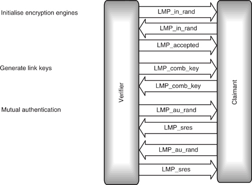
An example of a set of LMP messages used to initialise encryption, generate combination keys, and authenticate are shown in Figure 15–7. It is worth noting that the messages exchanged during this process changed between version 1.0b and version 1.1: in version 1.0b authentication took place after the generation of initialisation keys, as well as after generation of link keys. Authenticating twice slowed down the process and did not increase security, so the duplicate authentication was removed from version 1.1 of the Bluetooth specification.
Figure 15–7 LMP message sequence chart for authentication.
15.3.4 Changing Link Keys
If the host decides for some reason that the current link key may have been compromised, it can create a new link key using the HCI command HCI_Change_Connection_Link_Key. Because each connection uses a different link key, this command has a connectionHandle parameter to identify the connection on which the link key is to be changed. It may take some time for a new link key to be negotiated, so the Bluetooth module replies to this command with an HCI_Command_Status event.
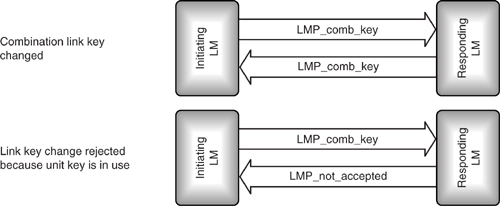
The sequence of LMP messages used to change the link key is shown in Figure 15–8. It is exactly the same as the messages used to negotiate the key in the first place. If the key is a unit key, it cannot be changed at the LMP level, so when a new combination key is sent, it will be rejected with an LMP_not_accepted message.
Once the new link key has been generated, an HCI_Link_Key_Notification event and HCI_Change_Connection_Link_Key_Complete event are sent to the host. Both devices also conduct mutual authentication after changing the link keys.
15.3.5 Changing to Temporary Link Keys
If broadcast information is to be encrypted, a temporary link key must be used. A temporary key is needed because when a device receives a packet, it must decrypt it immediately so that it can respond to any errors in the packet. A Slave device does not know until it receives a packet whether it is broadcast or point to point, and so does not have time to switch between a broadcast key and a link key. Since there is no time to switch keys, the device must use the same key for broadcast and point to point links.
Figure 15–8 Message sequence charts for changing a link key.
Because broadcasts are sent to every device in the piconet, the same broadcast link key must be used by all devices on the piconet. This means that devices which previously had individual link keys and could not read one another’s packets are now all using the same key, so security is compromised. Furthermore, the link key must be usable by all devices, so it must use the shortest key length of any of the devices in the piconet. Obviously if security has to be compromised in this way to implement broadcast encryption, the links should return to using their normal link keys as soon as broadcast encryption is switched off again; therefore, the link key used for broadcast is a temporary key.
Because only the Master can broadcast, it is the Master that creates the temporary link key. An HCI_Master_Link_Key command can be used by the host to force a Master to create and use a temporary link key. This command has a Key_Flag parameter which is used to specify the type of link key being created. Because some link management level negotiation must take place before the keys are in use, the module responds immediately with an HCI_Command_status event, and only sends an HCI_Master_Link_Key_Complete event when all LMP negotiations have taken place and the new key is in use. Both devices conduct mutual authentiocation to verify the new link key.
The temporary link key will only be valid for the current session, so every time a new encrypted broadcast session is started, a new temporary link key will need to be created (and mutual authentication is conducted to verify the key). Because the temporary link key is only used for a short period, temporary link keys cannot be changed (in version 1.0b any keys could be changed, but in practice temporary link keys never needed to be changed, version 1.1 removed the ability to change temporary link keys).
To create a temporary link key, the Master first creates a 128 bit master key, Kmaster. The Master creates this key by combining two 128 bit random numbers using the SAFER+ Encryption Engine. This Encryption Engine is used instead of using a random number directly in case the Master’s random number generator is not very good. By combining two random numbers in this way, an extra degree of randomness is introduced, making it much more difficult for a snooping device to guess the master key.
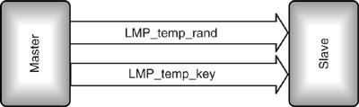
Having created the master key, the Master creates another random number and sends it to the Slave in an LMP_temp_rand message. Both Master and Slave then use the SAFER+ Encryption Engine to combine the random number and the current link key to create an overlay. The Master adds this overlay modulo-2 to the master key and sends the result in LMP_temp_key as shown in Figure 15–9.
Figure 15–9 Message sequence chart for changing to a temporary link key.
Because the Slave calculates the same overlay, it can extract the master key. Thus, as soon as it receives LMP_temp_key, it extracts the master key, mutual authentication takes place to verify the key, and it is then used as the current link key. Every time the link key is changed, encryption is stopped and restarted to ensure that all devices on the piconet have picked up the new key and are using the correct parameters.
The master key carries on being used until the end of the session, or until the link key is changed again.
15.3.6 Reverting to Semipermanent Link Keys
The semipermanent link keys are just the normal link keys used for point to point communications. For some devices, such as headsets, there may be no facility to enter new keys. For these devices the term “semipermanent” may be misleading, as the key used for point to point communications is permanently stored. For other devices the key may occasionally be changed and the term “semipermanent” is more accurate. The same HCI_Master_Link_Key command that was used to switch to a temporary key is used to switch back to a semipermanent key. Only the Key_Flag parameter is changed to specify that the key is reverting back to the semipermanent link key which was in use before the temporary link key.
Because the semipermanent link key is the link key which was in use before, both devices already know the key. This means that there is no need to send the key, so the LMP_use_semi_permanent_key message has no parameters. The Slave cannot refuse a request to return to using the semipermanent link key, so it simply acknowledges receipt of the message with LMP_accepted as shown in Figure 15–10.
Figure 15–10 Message sequence chart for changing to a semipermanent link key.

As for all other link key changes, when the piconet reverts to using the semipermanent link key, encryption must be stopped and restarted. The device which sent LMP_use_semi_permanent_key initiates authentication once encryption is back on to verify the new link key (arguably this check is redundant as it could tell the key was correct by successful decryption of data).
15.3.7 Storing Link Keys
In the procedure described above, a link key was created by negotiation. Link keys can also be set up by simply writing via the HCI, or the keys from one session can be read by the host, stored, and then written back later. Remembering link keys from previous sessions can obviously save the time involved in negotiation and get an encrypted link running faster. Many hosts have nonvolatile memory available, so having the host store data between sessions saves adding cost to the Bluetooth device. Another advantage of the host remembering keys is that if the host is something like a laptop with Bluetooth PCMCIA card, changing cards will not cause keys to change. Also, if the card is removed, security keys cannot be read from it. Keys stored on the host can be protected by passwords and so are potentially more secure than keys stored in a removable Bluetooth device.
Every time a new link key is generated, an HCI_Link_Key_Notification event is sent to the host. The parameters of this message are the new link key and the Bluetooth Device Address (BD_ADDR) of the device at the other end of the connection.
When the module wants to retrieve a link key from the host, it sends an HCI_Link_Key_Request event. This event has a single parameter: the Bluetooth Device Address of the device at the other end of the ACL link for which the link key is required. If the host can supply the link key, it is sent back in an HCI_Link_Key_Request_Reply command; if for some reason the host can’t supply a link key, it responds instead with a HCI_Link_Key_Request_Negative_Reply command.
The Bluetooth module does not remember link keys when power cycled. Since it tells the host every time a new link key is generated, the host should know all the link keys in use, but it is possible that a Bluetooth module which has its own power source may be connected to a new host, then the host would not know the keys in the module.
The host is provided with a HCI_Read_Stored_Link_Key command to retrieve link keys from the module. The module responds with the HCI_Return_Link_Keys event; this event has three parameters:
- Num_Keys—The number of link keys being requested.
- BD_ADDR[i]—An array of Num_Keys Bluetooth Device Addresses.
- Link_Key[i]—An array of link keys which match the Bluetooth Device Addresses.
The command HCI_Read_Stored_Link_Key can be used to read the key for a particular link, or to read all link keys. HCI_Write_Stored_Link_Key is used to store a key for a given link (the link is specified by the Bluetooth Device Address of the device at the other end of the link). A device may only be able to store a limited number of keys, so HCI_Delete_Stored_Link_Key can be used to remove link keys from storage.
15.3.8 General and Dedicated Bonding
Bonding involves setting up a link for the purpose of exchanging link keys, and possibly other security information. Because the device which initiates bonding is the device which sets up the connection by paging, when bonding, it is always the paging device which initiates authentication procedures.
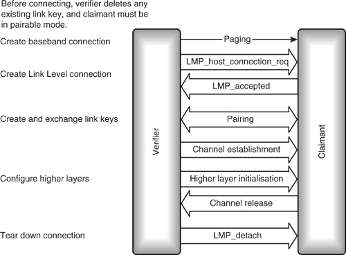
The Generic Access Profile divides bonding into two procedures: general bonding and dedicated bonding. Dedicated bonding happens when devices only create and exchange a link key. As soon as Link Level authentication procedures have completed, the channel is released before the higher layers connect. General bonding may involve exchange of data by higher layers to initialise their security parameters.
Link keys for bonded devices are stored by a Bluetooth device so that it does not have to create new link keys every time it connects. Since bonding involves creating a new link key, any old link key for the device being bonded with is deleted before bonding is performed. On devices with an HCI, the host can force deletion of a link key using the HCI_Delete_Stored_Link_Key command.
Because bonding involves pairing, the paged device must be in pairable mode before bonding can take place.
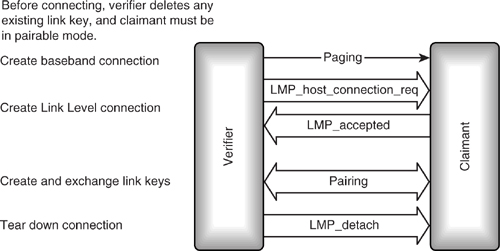
Figure 15–11 shows dedicated bonding. Note that there is no connection made above link manager level.
Figure 15–11 Dedicated bonding.
As Figure 15–12 shows, general bonding involves all the same steps as dedicated bonding, but in addition, an L2CAP channel is set up, and, depending on the application requiring security, higher layer channels may also be set up. Once such channels are set up, security information from higher layers may be passed across the channel. After higher layers are configured, the connection is torn down again.
Figure 15–12 General bonding.
Once two devices are bonded, they share a link key and can connect using that link key without having to go through pairing procedures again.
15.4 Starting Encryption
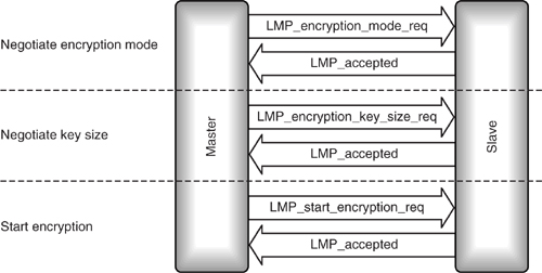
Once two Bluetooth devices have undergone authentication and agreed on a link key, there are three more steps before encrypted traffic can be exchanged:
- Negotiating encryption mode.
- Negotiating key size.
- Starting encryption.
The messages exchanged to start encryption are shown in Figure 15–13.
Figure 15–13 LMP message sequence chart for starting encryption.
15.4.1 Negotiating Encryption Mode
The encryption mode can be any one of the following:
- No encryption.
- Encrypt both point to point and broadcast packets.
- Only encrypt point to point packets.
On devices with an HCI, the encryption mode can be set using an HCI_Write_Encryption_Mode command and can be checked at any time using the HCI_Read_Encryption_Mode command.
The Link Manager uses an LMP_encryption_mode_req to request that the desired encryption mode be used on the channel. If the encryption mode is accepted, LMP_accepted is sent back; if it is not, LMP_not_accepted is sent, and the Master is free to try again, requesting a different encryption mode.
The encryption modecan be changed by resending the LMP_encryption_mode_req. Data transmission must be stopped when encryption mode changes; otherwise, data could be sent when the encryption mode is indeterminate, which would lead to data being corrupted or lost. To avoid this, data transmission is stopped before any encryption change. Version 1.0b of the specification said that data traffic had to be temporarily stopped, but there was some disagreement among implementers as to when to stop it: Should it stop immediately, at the end of an ACL packet, or at the end of an L2CAP packet? Version 1.1 of the specification clarified that data transmission should stop at the end of the current ACL packet with L2CAP data.
15.4.2 Negotiating Key Size
The United States has regulations governing the export of devices capable of using strong encryption schemes for encrypting data. To comply with these regulations, it is possible to manufacture a Bluetooth device which will not use the full 128 bit keys for encrypting data. Before encryption can be switched on, both units must agree on a key length to use. The Master begins by requesting the maximum key length it can use. If it is within the capabilities of the Slave, an LMP_accepted is returned; otherwise, an LMP_not_accepted is returned and the Master must try again with a shorter key. The Master keeps trying until it gets an LMP_accepted.
15.4.3 Starting Encryption
Once an encryption mode and key size has been chosen for the link, encryption can be switched on and off. The HCI_Set_Connection_Encryption command uses an ACL connection handle to identify the device which is having encryption switched on or off. When the link manager has finished negotiating encryption on the link, an HCI_Encryption_Change event is sent back to the host. No traffic should be sent on the ACL link while encryption is being enabled or disabled, as the link will be occupied with LMP traffic.
The final step is to send an LMP_start_encryption_req. Once the LMP_accepted reply has been received, encrypted data can be exchanged on the ACL link.
This section has described the Master driving encryption mode, but it is also possible for the Slave to send the messages to authenticate, pair, negotiate modes, and switch encryption on and off. We have also described a sequence where each message is exchanged in sequence at link setup, but it is equally possible for authentication to proceed at any time, and for link keys to be changed at any time, or indeed link keys from a previous encryption session could be stored and used.
15.4.4 Stopping Encryption
Since encryption does nor slow down traffic on a link usually once encryption has been started there is no need to stop it. However there may be a need to change encryption parameters after encryption has been started, and this cannot be done whilst encryption is active. Before making changes which affect encryption—for example, changing link keys—encryption is stopped, it is then restarted after the change.
In version 1.0b, the master could stop encryption with an LMP_stop _encryption_mode_req, but there was no clearly defined way for the slave to stop encryption. Version 1.1 specified that any unit wanting to stop encryption could send an LMP_encryption_mode_req with the encryption-mode parameter set to no encryption (zero). If the other device responds with LMP_accepted, the Master sends an LMP_stop _encryption_req message to stop encryption.
After any changes are made, encryption can be restarted using the same LMP_encryption_mode_req which was used to initially start encryption.
15.5 Security Modes
The Generic Access Profile defines three security modes:
- Security Mode 1 is nonsecure—Devices in Security Mode 1 will never initiate any security procedure. Supporting authentication is optional for devices which only support Security Mode 1.
- Security Mode 2 gives Service Level-enforced security—The channel or service using an L2CAP connection decides whether or not security is required. So until an L2CAP channel has been established, a device in Security Mode 2 will not initiate any security procedures. Once an L2CAP channel has been established, the device then decides whether or not it needs authorisation, authentication, and encryption, and goes through appropriate security procedures.
- Security Mode 3 is Link Level-enforced security—A device in Security Mode 3 initiates security procedures before it sends an LMP_setup_complete message. If security measures fail the device, the connection will not be set up. It is possible to set up devices supporting Security Mode 3 so that they will only connect with pre-paired devices. In this case, they would reject an LMP_host_connection_req from any other devices (they would reply with an LMP_not_accepted message).
In addition to these specific security modes, the other modes of a Bluetooth device may be used to increase security. For maximum protection of data, a device can be set in nonconnectable mode when it is not in use. In this mode, the device will not respond to paging, so other devices cannot connect with it.
Nondiscoverable mode can be used to stop a device from responding to inquiries. If this is used, then only devices which already know the device’s Bluetooth Device Address can connect to it.
15.6 Security Architecture
The Bluetooth security white paper defines a security architecture which may be used to implement Mode 2 Service Level-enforced security on Bluetooth devices. Because the implementation of security at Service Level does not affect interoperability, the white paper is purely advisory and is not a Bluetooth specification.
15.6.1 Security Levels
In addition to the authentication procedures defined in the Bluetooth specification, the security white paper introduces the concept of an authorised or trusted device. An authorised device has been specifically marked in a server’s database as having access to a service.
Devices and services can be divided into different security levels. The security white paper splits devices into three categories and two trust levels:
- Trusted devices—Paired or bonded devices which are marked in a database as trusted, and can be given unrestricted access to all services.
- Known untrusted devices—Devices which have been paired or bonded, but are not marked in a database as trusted; access to services may be restricted.
- Unknown devices—No security information is stored, the device is untrusted, and access to services may be restricted.
It would also be possible to implement different levels of trust for services as well as devices. For example, reading and writing to a calendar could be defined as different services. Read access to the calendar might be restricted to a range of devices known to belong to co-workers who had an interest in seeing appointments. Write access to the calendar might be restricted to a smaller set of devices belonging to the owner of the calendar.
The security white paper suggests that the security requirements for authorisation, authentication, and encryption of services could be set separately. This gives three security levels for services:
- Open services—Any device may access these; there are no security requirements.
- Authentication-only services—Any device which can go through authentication may access these (authentication proves it shares a secret key with the service provider).
- Authentication and authorisation services—Only trusted devices may access these (trusted devices are recorded as trusted in the server’s database as well as having a secret key).
Each service should have its security level set independently, so a device having access to one service does not imply that it has access to others. It should be possible to define a default level of security which will apply to all services, unless they are specifically set to a different level.
15.6.2 The Security Manager
The existence of trusted devices and of different levels of authorisation for different services imposes a requirement for databases to hold device and service information.
Different protocols will wish to access the information in these databases according to the profile being implemented; for instance:
- L2CAP will enforce security for cordless telephony.
- RFCOMM will enforce security for dialup networking.
- OBEX will use its own security policy for file transfer and synchronisation.
To allow uniform access to the databases by all layers, a security manager handles security transactions with the various layers. All exchange of information with the security databases goes through the security manager as illustrated in Figure 15–14.
Figure 15–14 Security architecture.

Applications and protocols wishing to use security features register with the security manager. The security manager stores security information in the security databases on behalf of the rest of the system. Security policies are enforced by exchanging queries with the security manager:
- Applications query to find out whether a particular device is allowed to access a service.
- HCI queries to find out whether to apply authentication and/or encryption to a connection.
- The user interface is queried by the security manager to get PINs.
- The user interface is queried by the security manager to authorise new devices.
- Protocol layers query the security manager with access requests.
The device database holds information on whether devices are authenticated and authorised. The service database holds information on whether authorisation, authentication, and encryption are required for access to a service.
The security white paper suggests that if a service has not registered with the service database, then the default settings should be:
- Incoming connection—Requires authorisation and authentication.
- Outgoing connection—Requires authentication.
As the security white paper is not a part of the Bluetooth specification, there is no requirement to implement security in the way suggested by the white paper. However, designers implementing security in Bluetooth devices should consider the white paper’s recommendations.
15.6.3 Setting up Security on New Connections
Because it is the service that decides the level of security to be enforced, security cannot be enforced when an ACL (data) connection is first set up. Instead, security is enforced only when access is requested to a protocol or service which requires security. The protocol or service requests access from the security manager. The security manager looks up the service or protocol in the service database to see what level of security to impose. Then it looks up the connecting device in the device database to see whether it meets the requirements of the service. If necessary, the security manager enforces authentication and/or encryption, and sends any necessary queries for PINs or authorisation to the user interface. Access is then granted or refused, and if access was granted, the service can be used.
It is possible that some services may use a connection without encryption, then another service will begin using the service which requires encryption. Encryption will be set up for the service which requires it, but other than a short pause in traffic while LMP messages are exchanged, this will not be apparent to the other services.
Other than the link management messages required to configure security, there is no impact on bandwidth. The same number of bits are sent on air for an encrypted link as are sent on an unencrypted link.
15.7 Summary
Bluetooth has powerful security features with the SAFER+ encryption engine using up to 128 bit keys.
At the Link Level, it is possible to authenticate a device: This verifies that a pair of devices share a secret key derived from a Bluetooth passkey, also known as a Personal Identification Number (PIN). The Bluetooth passkey is either entered in a user interface, or, for devices such as headsets which do not have a user interface, it can be built in by the manufacturer.
After authentication, devices can create shared link keys which can be used to encrypt traffic on a link. The combination of authentication and creating link keys is called pairing. At the Application Level, pairing, possibly accompanied by exchange of higher level security information, is called bonding.
Authentication may be repeated after pairing, in which case the link key is used as the shared secret key.
Three modes of security can be implemented: Mode 1 is not secure, Mode 2 has security imposed at the request of applications and services, and Mode 3 has security imposed when any new connection is established.
A Bluetooth security white paper suggests an architecture for implementing security in the higher layers of a Bluetooth protocol stack. This is based on Mode 2 security. In addition to being authenticated by the link management procedures, the security architecture introduces the idea of devices being authorised by a user to use particular services. The security architecture suggests implementing this through a pair of databases: one holds information on which devices are authenticated and/or authorised, and the other holds information on whether services require authentication, authorisation, and/or encryption. Services and protocols register with a central security manager, which handles access to the databases. After registration, the central security manager grants permissions to use services.
Security is essential to many applications which will use Bluetooth links, but hiding the complexity of Bluetooth security from the user is essential if Bluetooth devices are to be easy to use. Through the security architecture, it is possible to implement security at a variety of levels with minimal intervention from the user.