
6
Audio
6.1 Introduction
A major application for Bluetooth is as a carrier of audio information. Indeed, we have already seen that up to three full–duplex audio channels are provided for in the standard. This functionality allows us to build devices such as wireless headsets, microphones, and headphones using Bluetooth for all manner of consumer products such as cellular phones, call centre switchboards, or even personal music playback. The audio quality provided by Bluetooth is the same as one would expect from a cellular telephone (not surprising since Bluetooth uses the same audio data format as the GSM system).
Audio data is carried via Synchronous Connection–Oriented (SCO) channels and through the use of several coding schemes. Different trade–offs of quality and robustness are available.
This chapter explains how this capability is provided, how to control it, and what limitations exist. We begin at the bottom of the protocol stack by explaining the physical interfacing and coding operations involved, and work our way up the stack looking at how the audio subsystem of a Bluetooth device is configured and controlled. We conclude by examining the level of performance and quality one can expect from Bluetooth so as to allow us to make qualitative judgements on the suitability of Bluetooth audio transmission and reception for a given application.
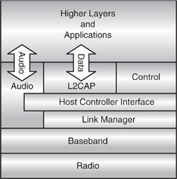
Figure 6–1 Position of audio in the Bluetooth protocol stack.
6.2 Audio Transports In The Protocol Stack
The standard specifies that audio should be carried on SCO channels, while data is carried on ACL channels. Version 1.0b of the standard only defines profiles and transport mechanisms for SCO via HCI in the same way as for ACL; see Figure 6-1.
However, packets crossing the HCI are flow controlled and are subject to variable latency due to the microcontroller executing the HCI and LM tasks. These interruptions in the audio path can lead to SCO packet loss or a requirement for expensive buffering in the baseband. To avoid such complications, many implementers use a direct PCM route1 to interface the audio CODECs directly to a serial digital PCM stream at 8kHz.
1 The direct PCM route was originally presented as an HCI transport mechanism in the Bluetooth white papers, which were a precursor to the specification. However, the PCM transport did not make it into either the 1.0b or present 1.1 specifications, although there is some mention of it in the baseband part of the standard.
6.3 Quality And Bandwidth
The correct way to evaluate audio quality is to use subjective techniques, especially because the various compression schemes in current use exploit the way that the human ear interprets the audio signal. However, a simple way to evaluate the audio quality delivered by a Bluetooth SCO link is to compare the un–coded audio bandwidth and sampling size with that of other audio systems, as shown in Table 6–1. Note how the data rate reduces as more or stronger compression or coding is used.
Clearly, a Bluetooth SCO link can not encode and carry raw CD quality sound. However, with suitable compression, such as MP3 (MPEG Layer 3 Audio) it would be technically feasible to use an ACL channel2 for high quality audio, although version 1.1 of the specification does not define a profile for such a device.
2 The maximum asymmetric data rate for a Bluetooth ACL link is 723.2 kb/s, which would comfortably carry MP3–coded audio. However, the coded audio data rate must be sustained.
Table 6–1 Comparison of Audio Data Rates
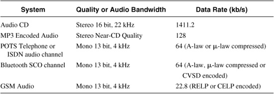
The level of audio quality provided by a SCO link is approximately equivalent to that of a GSM cellular telephone audio channel. Not surprising considering the origins of the Bluetooth standard.
6.4 SCO Links
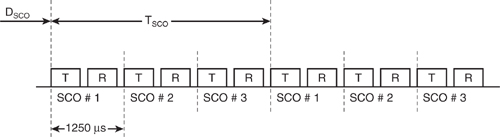
When SCO link is established via the initial ACL link setup and subsequent SCO link negotiation, the packets are exchanged on air as shown in Figure 6–2, where DSCO and T SCO are the start offset and repeat period respectively, as defined in Chapter 4. One, two, or three channels are possible, however, in each case, the bandwidth of each channel is always 64 kb/s. This can be shown as follows:
On each channel, new packets comprising n bits are sent and received once every TSCO slots. Thus, the number of bits passed in each direction per second is:
![]()
where TSCO = 6 and n = 240 for an HV3 packet. For more protected SCO packets, where less source data is carried, TSCO must be reduced to maintain the source bandwidth. For an HV2 packet (FEC = 2/3), TSCO = 4, n = 160, and for an HV1 packet (FEC = 1/3), TSCO = 2, n = 80.
This places a basic requirement on the audio to be carried by Bluetooth and is a fundamental reason for the need to use audio coding techniques, since 64 kb/s does not provide satisfactory audio quality for typical Bluetooth applications. By comparison, the raw, linear PCM audio bandwidth of a GSM cellular phone before speech transcoding is 104 kb/s. The other fundamental reason for using any audio coding is to increase robustness to noise and on–air error sources.
Figure 6–2 SCO channel timing.
6.5 Audio Codecs
Bluetooth specifies three different audio coding techniques: Log PCM coding using either A–law or –law and CVSD (Continuous Variable Slope Delta modulation). The 64–ksamples/s source signal must be band limited to 4kHz to prevent aliasing in the encoder.
6.5.1 Log PCM
Log PCM coding is used in a whole manner of existing devices such as fixed-line telephone handsets and the PSTN (Public Switched Telephone Network). Log coding compresses the input data via a logarithmic transfer function so as to represent the more accurate (higher bit width) data with a less accurate (lower bit width) output value. However, the logarithmic transfer function ensures that the effect of the compression gives rise to a minimal decrease in quality as perceived by the human ear.
The specification of the exact characteristics are defined by the International Telecommunications Union (ITU-T), recommendation G.711, which provides conversion tables to and from linear PCM and log PCM for both A–law and -law compression. These tables are based on an approximation of the logarithmic function by a series of linear segments.
The input to the log PCM encoders is up to 3 channels of 13 bit (for A–law) or 14 bit (forμ–law) linear PCM at 8kHz, while the output is up to 3 channels of 8 bit encoded data at 8kHz.
6.5.2 CVSD
CVSD is a more complex technique than log coding, which exploits the strong correlation between adjacent audio samples by quantising the difference in amplitude between the two samples as opposed to the entire sample amplitude. This requires fewer quantisation steps for the same signal quality, and consequently lower bandwidth. Generally referred to as DPCM (Differential PCM), this approach can be modified to reduce the required bandwidth even further by making the quantisation step adaptive, so–called ADPCM (Adaptive DPCM). This technique represents low–amplitude signals with acceptable accuracy without sacrificing performance on large–amplitude signals.
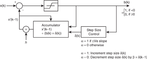
Figure 6–3 CVSD encoder block diagram.
In essence, CVSD is ADPCM with delta modulation, where only two levels are used to represent the differential in amplitude or delta. Because a single binary digit is used to represent each sample, the sample rate and bit rate are equal, and as a consequence, the signal quality (SNR) is directly related to the sample rate. By transmitting the delta signal as a sequence of single bits on air, CVSD is much more robust to random bit errors in the channel than the log PCM techniques described above.
The use of a 64-kb/s CVSD CODEC provides toll quality speech, which is acceptable for most Bluetooth applications. Indeed, due to its encoded nature and low bandwidth but acceptable quality, CVSD has often been used in military communications systems since it was first proposed by Greefkes and Riemens in 1970.3
3 J.A. Greenfkes and K. Riemens, “Code Modulation with Digitally Controlled Companding for Speech Transmission,” Philips Technical Review, pp. 335-353, 1970.
6.5.2.1 CVSD Operation. The CVSD encoder and decoders are shown in Figures 6–3 and 6–4, respectively.
The step size is crucial to the performance of any delta modulation scheme. If small, tracking of slowly changing, low amplitude signals is good at the expense of poor tracking of fast, abruptly changing signals. When the step size is such that the CODEC is unable to keep up with the input signal, a phenomenon called slope overload occurs (see Figure 6-5).
Increasing the step size will reduce the problem of slope overload at the expense of increased noise due to the resulting large grained quantisation steps. Ultimately, low amplitude signals are not quantised accurately enough and they appear as an alternating one–zero pattern. Since an alternating one–zero bit pattern has a mean value of zero, the decoded output signal will integrate to zero and the signal will be lost. By adjusting the quantisation step size, CVSD makes a compromise between these two extremes.
Figure 6–4 CVSD decoder block diagram.
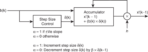
The step size, δ(k), increases whenever a certain proportion of the previous bits are the same. In other words, if the input slope is seen to be going in the same direction relative to the CVSD approximation, then the step size is increased to catch up with it. This is accomplished by increasing the step size if the previous four bits are identical, that is, if the input has been consistently ahead of (greater or smaller than) the CVSD approximation for four consecutive bits.
The syllabic companding parameter, , determines when to increase the step size (when the last four input bits are the same) or allow it to decay (when not). The step size decay time, β, is related to the length of a speech syllable. Although a human speech syllable is around 100ms in duration, pitch changes are around 10ms in duration. Bluetooth specifies a βwhich corresponds to 16ms.
Figure 6–5 CVSD slope overload.

Figure 6–6 Effect of large decay factor.

The accumulator decay factor, h, determines how quickly the output of the CVSD decoder returns to zero in the absence of a strongly changing input. Bluetooth specifies an h which causes the output to decay to zero on the order of 0.5ms. The specification is rather vague on the reasoning behind the choice of such a large value for the accumulator decay h. As illustrated in Figure 6–6, the large decay factor means it can require several positive steps to recover from a single negative step. Indeed, positive steps are lessened by the decay, while negative steps are enhanced. This follows since the step parameter δ only operates when x(k) <x1(k–1) and b(k) = 1.
Bluetooth specifies 0.1% raw BER from the radio under various test conditions. Since audio data is not retransmitted and may not use FEC, this BER of 0.1% will be evident at the input to the CVSD decoder. Simulation shows that a BER of 0.1% does not significantly degrade the quality of the CVSD decoder output. A BER of 1% is quite noticeable, while a BER of around 5% and above causes the output to become unintelligible.
Bluetooth specifies the sample input and output to the CVSD CODEC as 16 bit signed.
6.5.2.2 Sample Rate Conversion (Interpolation and Decimation). Clearly, the processing frequency for log PCM and CVSD are not the same; Log PCM processes 13 or 14 bit samples and 8 bit symbols at 8kHz, while CVSD process 16 bit samples and single–bit symbols at 64kHz. It is possible to simply configure the PCM interface of the audio subsystem to operate at either 8kHz or 64kHz as appropriate and indeed with only analog / digital converters connected to the CODECs, this is acceptable. However, the extra information represented by the 16 bit samples at 64kHz are redundant and merely a side effect of the CVSD process. Furthermore, the effective data rate is far too high to make it sensible to pass on to another device as it is, particularly if the audio is to be routed via HCI. Therefore, it is necessary to interpolate and decimate so as to reduce the 64kHz sample data rate to the same 8kHz rate as that required for the log PCM CODECs.
This up sampling to 64kHz and down conversion to 8kHz must not introduce any significant noise above 4kHz. The simplest way to achieve this is by using a low–pass FIR filter with a sufficient number of taps. The baseband input data is interpolated from 8kHz up to 64kHz by the filter, which is clocked at 64kHz. For down–conversion, only every eighth output is used, but again filtering is required. The resulting data stream should exhibit negligible difference in power spectral density with respect to the input signal.
6.6 Audio Subsystem
Figure 6-7 shows a block diagram of a typical Bluetooth audio subsystem. As described, the log PCM encoding and decoding functions share a common path to and from the PCM
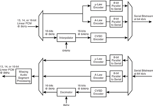
data at 8kHz; the CVSD CODEC, however, requires interpolation and decimation. Each of the blocks shown has already been discussed, except for one labeled “Missing Audio Segment Processing.”
6.6.1 Error Handling (Missing Audio Segment Processing)
Although some SCO packets are protected by FEC, none of the audio traffic is protected by a CRC and re–transmission is of course not possible due to the time-bounded nature of SCO data. Further, although much has been made of the robustness of CVSD to random bit errors, it is always possible that sufficient errors will occur so as to render a packet unusable. Although errors will not be detected in the packet payload, it is quite likely that the access code may be rejected or that the HEC will fail. In such situations, there will not be a valid audio packet for the CODECs to decode and so a mechanism for filling in or masking the missing data is required. The simplest technique is to repeat the decode of the previous packet again. A more sophisticated approach (and probably the acceptable minimum) is to dither the subsequent “repeat” packets with a random white noise to reduce the possibility of an audible tone due to the discontinuity clicks between packet repeats. If a new packet is not received after a predetermined time, it may also be necessary to fade the audio level to avoid the repetition becoming audible.
Since CVSD is a differential scheme, the decoder output depends on many previous symbols (unlike log PCM). When data is lost, the information about the current status of the accumulator and the step size is also lost. There are various ways to restart the algorithm when a new packet arrives. The simplest way is to reset the step size and accumulator to their initial values upon receipt of a new packet. The algorithm recovers itself quickly, and even for multiple missing bursts, the effect on sound quality is small.
6.7 Audio Data Formats And Hci
HCI uses the command HCI_Write_Voice_Setting to configure the audio subsystem and HCI_Read_Voice_Setting to read back the configuration status. The voice setting parameters apply equally to all audio channels and specify the baseband format for audio samples together with the chosen on-air coded format. Table 6–2 summarises the various parameters which comprise the two byte Voice_Setting commands and their meaning.
The specification of the HCI voice settings shows clearly that not only can the onair coding format be chosen from CVSD, A-law, and μ-law, but so too can the sample input / output data be chosen from three options: linear PCM, -law log PCM, and A-law log PCM. This avoids the need to decode in the host and re-encode in the Bluetooth device if the host device already handles audio data in a log PCM encoded form—as is the case in much PSTN equipment.
This choice of input formats leads to another complication in the audio subsystem, which is the requirement to be able to convert from A-law and -law into -law and A-law, or even CVSD where the chosen input format is not linear PCM. Although the ITU-T G711 recommendations provide conversion tables for A to -law and to A-law, due to the need to support CVSD, it is arguably more elegant to simply utilise the existing CODECs to return the data to linear PCM before re-encoding it appropriately.
Table 6–2 HCI Voice Setting Parameters
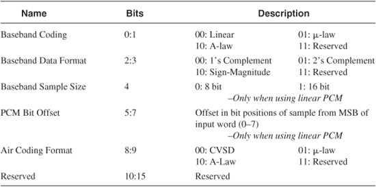
The choice of 8 or 16 bit sample size only applies to linear PCM since log coded data will always be 8 bits wide. When the sample data is 13 or 14 bits wide for log coding, the PCM bit offset parameter defines the displacement of the sample word within a 16 bit field.
6.8 Implementation
To implement an audio processing subsystem for Bluetooth, the subsystem above must be replicated for a maximum of three channels, either physically or temporally, and interfaced to a PCM data stream.
The higher layers of the standard describe HCI based SCO, where audio passes through the HCI via the protocol stack. The HCI route for audio is suitable where audio data is received directly by the HCI via a microcontroller interface, as may be the case with PC sourced audio. However, early Bluetooth white papers also described PCM based SCO—a transport route for audio PCM source data directly into and out of the CODEC subsystem via a dedicated PCM port. In the version 1.1 specification, this transport interface was not defined. However, it was hinted at in the baseband section, and indeed, has been implemented by the majority of Bluetooth component designers and manufacturers. The direct route to the CODECs is suitable for applications where digital audio is available directly, such as in cellular telephone, headset, or microphone applications.
6.8.1 Interfacing to Host Device Audio Levels
The specification again refers to the ITU-T G711 recommendations on audio levels and frequency response.
6.9 Summary
Audio is a fundamental component of the Bluetooth specification, which is capable of supporting up to 3 full duplex audio channels simultaneously. These SCO channels use pre-reserved slots to maintain temporal consistency of the audio carried on them. Because Bluetooth is a wireless protocol data, it may be corrupted in transmission by random interference. To compensate for this Bluetooth uses a delta modulation technique called CVSD. For higher quality over a good link Bluetooth also provides A-law and -law log PCM capability.
There are two routes for audio to pass through a Bluetooth system: to and from the HCI as data in HCI packets and via direct PCM connection to the baseband CODECs. The HCI route has some deficiencies in carrying audio data, such as HCI flow control holding up audio data in a system carrying mixed voice and data. The direct PCM route is not well specified in the Bluetooth specification, but is very common in commercial implementations.
The audio capabilities of Bluetooth are very suitable for “toll quality” voice applications such as between cellular mobile phone handsets and associated headsets. However, for higher quality audio applications such as hi-fi music, a far better alternative would be to send compressed audio using Bluetooth ACL data links.