
4
Baseband
4.1 Introduction
We begin this chapter by making some clear distinctions between the terms “Link Controller” and “Baseband” (see Figure 4–1). The Bluetooth specification uses these terms somewhat ambiguously, and a clear distinction will provide a useful handle on which to hang some later concepts.
Figure 4–1 Link control and the baseband.
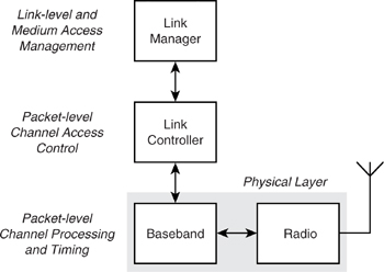
The Link Controller (LC) is responsible for carrying out link level operations over several data packet durations in response to higher level commands from the Link Manager (LM). The local and remote LC entities will manage the packet by packet process of establishing the link once commanded by LM and will maintain the link once established. The OSI Physical (PHY) layer is represented by the radio and the baseband. The radio interfaces between the on-air channel medium and the digital baseband, which formats data supplied by the LC for robust and reliable transmission over the channel and retrieves data from the channel for passing up the stack. The baseband is responsible for channel coding and decoding and low level timing control and management of the link within the domain of a single data packet transfer.
4.2 Bluetooth Device Address
Each Bluetooth device has a 48 bit IEEE MAC address known as the Bluetooth Device Address (BD_ADDR). This is used as a seed in some of the serial bit processing operations, and in particular for the derivation of the access code. The MAC address is split into Non-significant Address Part (NAP), Upper Address Part (UAP), and Lower Address Part (LAP) as follows:
- BD_Addr[47:32] – NAP[15:0]
Used to initialise the encryption engine stream LFSR. - BD_Addr[31:24] – UAP[7:0]
Used to initialise the HEC and CRC calculations and for frequency hopping. - BD_Addr[23:0] – LAP[23:0]
Used by sync word generation and frequency hopping.
4.3 Masters, Slaves, And Piconets
Bluetooth is a Time Division Multiplexed (TDM)1 system, where the basic unit of operation is a slot of 625 μs duration. In connection (i.e., transferring data), all transmit or receive operations occur in 1, 3, or 5 slots (a packet). In preconnection operation (i.e., the inquiry, paging, or scanning operation which precedes a connection), transmit and receive can sometimes occur in half slots. The packets are joined together in transmit and receive pairs. In connection, a packet pair can be 2, 4, 6, 8, or 10 slots long.
1 Strictly speaking, it is also Frequency Division Multiplexed (FDM) as well due to the use of frequency hopping. However, this is not used to increase a link’s capacity, but rather to increase robustness and reuse of the same spectrum.
Each Bluetooth device may be either a Master or a Slave at any one time, though not simultaneously. These two roles are defined as follows:
Master—The device which initiates an exchange of data.
Slave—The device which responds to the Master.
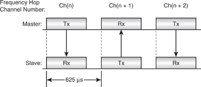
In addition, when communicating, Slave devices will utilise the timing of their Master and hop in synchronisation. With reference to Figure 4–2, the Master first transmits to the Slave device. This occurs with both devices tuned to radio channel Ch(n) 625 μs later, the two devices retune their radios, or “Hop” to Ch(n+1), and now the Slave is not only allowed to transmit, but indeed must respond whether it successfully understood the last packet or not. Following the Master’s reception slot, the Slave will now once again listen for a message. However, the Master may choose to transmit to someone else, or not transmit at all. The Slave will not transmit again until the Master again transmits to it.
Figure 4–2 Slot timing for single-slot packets.
Each device will hop once per packet. This is a fundamental part of the Bluetooth system and provides the following features:
- Security—Since the hopping is to a defined pseudo random sequence based on the device address of the Master.
- Reliability—Since if a particular radio interferer causes a packet to be lost on Ch(n), it is unlikely to be such a strong interferer on Ch(n+m), where n+m is guaranteed to be a significant distance from n due to the pseudo random hopping algorithm.
Bluetooth defines data packets which are 1, 3, or 5 slots long, and Figure 4–3 shows how the timing changes slightly for these multi-slot packets. Using a longer length packet allows higher data rates at the cost of reliability. Enough bursts of errors or interference to cause a packet to be rejected are more likely to occur during one single long packet on the same channel than in every single one of a number of shorter packets on different channels.
Figure 4–3 Slot timing for multi-slot packets.
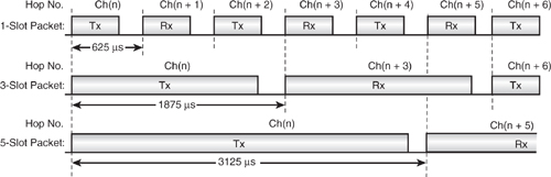
All packets have the same header and control data overhead, and so multi-slot packets are more data efficient. Also, since it is impractical to hop during a single packet due to the long radio settling time, the maximum amount of time is used for data transfer.
So, a Master is in control, deciding what—if anything—to transmit (1, 3, or 5 slot packet) and when to transmit it. The Slaves sit quietly, listening at the expected time, and any Slave hearing a packet with its own address receives the packet and responds to it.
Bluetooth would be a useful technology if all it did was facilitate point to point communication; however, it is much, much more than this. In fact, Bluetooth creates a kind of miniature Local Area Network (LAN); of course there is yet another Bluetooth buzz-word for this: “piconet”.
A piconet is an arbitrary collection of Bluetooth-enabled devices which are physically close enough to be able to communicate and are exchanging information in a regular way. A piconet is formed by a device configured as a Master, who “owns” the piconet, and between one and seven devices that always act as Slaves to this Master. All Slaves adopt the timing of the Master and will respond to any messages that include the Master’s “Access Code” (derived from the Master’s device address).
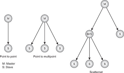
Figure 4–4 illustrates the topology of a point to point link between Master and Slave, together with a typical piconet. The third diagram shows something slightly different. Here, we have a Master with three Slaves, but the Master is itself a Slave belonging to another Master device. This is the so called “Scatternet.” Since Bluetooth has a limit of seven Slaves in a piconet, it may be desirable to link piconets together to form either wider physical coverage areas or just to link together more than eight devices. We will discuss the exact mechanism for this later, but essentially this is achieved by the Master device switching roles on a TDM basis between Master in its own piconet and Slave in the other Master’s piconet. This is illustrated in the diagram by the M/S label.
Figure 4–4 Piconets and scatternets.
As mobile devices move around, they can easily move out of range and lose contact with the piconet. Each link has a supervision timeout, which ensures that such links are closed down.
This ability of devices to move around makes a Bluetooth piconet very different from a traditional wired network. Because it is much more dynamic, network participants can be changing constantly. This makes the normal network administrator function far too cumbersome for administration functions such as network configuration and adding new members. It is for this reason that such networks are referred to as “ad-hoc” networks. The Bluetooth Link Controller has specific operations which can detect new devices in range and can easily form links to them.
4.4 System Timing
Before we look at the actual structure of the various Bluetooth packets and how a device addresses messages to specific other devices, it is useful to focus a little more on system timing and to understand the concept of the Bluetooth clock.
Like many communications protocols, Bluetooth synchronises most operations to a real time clock or time of day counter. This ensures that we can, for example, synchronise Tx-Rx data exchanges between devices, differentiate between lost and re-sent packets, and generate a predictable and reproducible pseudo random sequence of frequency hop channel numbers. The Bluetooth clock is a 28 bit count which is reset to 0 at power up and free-runs thereafter, incrementing every half slot, or 312.5 μs. It wraps approximately once per day. Every device has its own “Native” free-running counter that controls the timing and operation of that device. The native clock is referred to as CLKN.
If a device is operating as a Master it controls the piconet, and so it uses CLKN as its internal reference timing. If a device is operating as a Slave, then its timing must be exactly synchronised to that of its Master. Synchronising to the Master ensures that a Slave’s Rx and Tx slots line up correctly with the Master’s and that it chooses correctly matching hop channel numbers. To synchronise with the Master, a Slave must add an offset value onto its own native clock (CLKN) (see Figure 4–5). This offset derives a new clock value, CLK, which is its estimate of the Master’s CLKN. This is also referred to as the “piconet clock.”
Figure 4–5 Conceptual Bluetooth CLK offset application
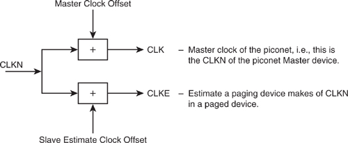
There is one other clock value defined in Bluetooth: CLKE, which is derived by adding another offset to CLKN. It is used by a Master to create an estimate of the CLK in a Slave device. This is used in the specific case of establishing a connection with a Slave before the Slave has synchronised to the Master. This will be explained later when we look at establishing a connection using the paging procedures.
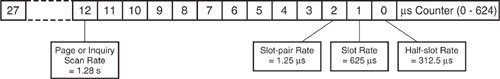
The lowest two bits of CLK are directly used to delimit the slots and half slots for packet transmit and receive. They also set the criteria for the choice of Tx or Rx, depending on whether the device is acting as a Master or a Slave. A Master transmission in connection always starts when CLK[1:0] = 00, and a Slave transmission in connection always starts when CLK[1:0] = 10. Figure 4–6 shows how CLK[27:0] is driven from the 1 μs symbol timing and how the lower parts of the clock, CLK[12:0], control the most important Bluetooth time periods.
Figure 4–6 The Bluetooth clock.
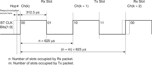
Figures 4–7 and 4–8 illustrate the use of CLK[1:0] and introduce the “Uncertainty window,” which accommodates any variation in the system timing between two communicating devices. The receiver in the Slave will be enabled some time earlier than we would expect the Master’s transmission to begin, and in the event of no transmission from the Master, the Slave’s radio will be turned off only after a timeout delay. This straddling of the “ideal” Rx start point allows timing drift to be accommodated and the Slave to resynchronise each time it receives. All devices perform a correlation against the first part of the packet; the “synchronisation word” so as to realign their timing to the start of the transmitting device. A Master will simply receive this packet on the resynchronised timing, while a Slave will actually change its system timing to match that of the Master’s. If a Master has not transmitted to a Slave for some time, the Slave will resynchronise within this window. In a connection, the uncertainty window is normally set to ± 10 μs. This allows for a Slave to be left alone for up to 800 slots, assuming a worst case of ± 20 ppm accuracy on each of the Master’s and Slave’s timing references.
Figure 4–7 Tx-Rx cycle of transceiver in normal Master mode.
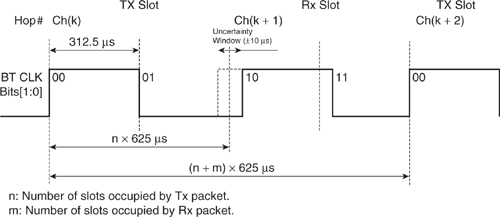
Figure 4–8 Tx-Rx cycle of transceiver in normal Slave mode.
4.5 Physical Links: Sco And Acl
A link is established between a device acting as Master and a device acting as Slave. Once a link has been set up, there are two basic types of data packets that may be exchanged with one very important distinction between the two—each is characterised by the two following link types:
- Asynchronous Connection-Less (ACL).
- Synchronous Connection Oriented (SCO).
4.5.1 ACL
An ACL link exists between a Master and a Slave as soon as a connection has been established. A Master may have a number of ACL links to a number of different Slaves at any one time, but only one link can exist between any two devices. As described above, the Master does not always transmit to the same Slave in a regular fashion. Thus the ACL link provides a packet-switched connection where data is exchanged sporadically as and when data is available from higher up the stack. The choice of which Slave to transmit to and receive from is up to the Master on a slot by slot basis, and so both asynchronous and isochronous (time bounded) services are possible. Most ACL packets facilitate error checking and retransmission to assure data integrity.
ACL links carry data to and from either the L2CAP or LMP layers. All user data is sent through L2CAP and passed to the baseband as L2CAP packets. Configuration and control of the links is carried out by the two opposing LM entities, and the associated command and control data is passed to the baseband as LMP packets. We will discuss this further in the section on logical links. Data is carried in DH (Data High rate) packets and DM (Data Medium rate) packets; the medium rate packets carry less data, but provide extra error protection.
A Slave may only respond with an ACL packet in the next Slave-to-Master slot if it has been addressed in the preceding Master-to-Slave slot. If the Slave fails to decode the Slave address in the packet header, it does not know for sure whether it was addressed or not and so is not allowed to respond.
Broadcast packets are ACL packets that are not addressed to a specific Slave and so are received by every Slave.
4.5.2 SCO
A SCO link is quite different and provides a symmetric link between Master and Slave with reserved channel bandwidth and regular periodic exchange of data in the form of reserved slots. Thus, the SCO link provides a circuit-switched connection where data is regularly exchanged, and as such it is intended for use with time-bounded information such as audio.
A Master can support up to three SCO links to the same Slave or to different Slaves. A Slave can support up to three SCO links from the same Master. Due to the time-bounded nature of SCO data, SCO packets are never retransmitted.
The Master will transmit SCO packets to the Slave at regular intervals, defined by the parameter TSCO. This is referred to as the “SCO interval” and is counted in slots. The Slave is always allowed to respond with a SCO packet in the reserved response slot, unless it correctly decoded the packet header and discovered that it had not been addressed as expected. If the packet was incorrectly decoded due to errors, then the Slave may still respond as the slot is reserved. Indeed, in normal operation, the Master is not allowed to transmit elsewhere in the reserved slot. An exception is a broadcast LMP message, which would take precedence over the SCO link.
A SCO link is set up by a Link Manager (LM) command from the Master to the Slave. This message will contain timing parameters to specify the reserved slots such as the SCO interval, TSCO, and the starting offset, DSCO. To avoid offsets being introduced by clock wrap-arounds, an initialisation flag in the setup command indicates which one of two initialisation procedures to use. The SCO link then commences as follows:
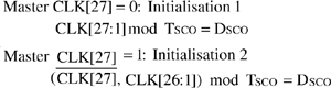
From now on, SCO data will be exchanged every TSCO slots.
A device must schedule any ACL traffic around reserved SCO slots so as to preserve the integrity of the SCO link. The one exception to this are Link Management control packets, which are allowed to override the SCO link since there must be a way to shut down SCO links in the event all bandwidth is reserved.
4.6 Bluetooth Packet Structure.
This section introduces the different types of packets that are used for communicating over interdevice ACL and SCO links. We break down the packets into their constituent parts such as access code, packet header, payload header, and payload.
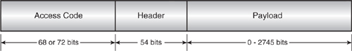
Every packet consists of an access code, a header, and a payload as illustrated in Figure 4–9. The access code is used to detect the presence of a packet and to address the packet to a specific device. For example, Slaves detect the presence of a packet by matching the access code against their stored copy of the Master’s access code. The header contains all the control information associated with the packet and the link, such as the address of the Slave for which the packet is intended. Finally, the payload contains the actual message information if this is a higher layer protocol message such as might be sent from L2CAP or LM, or the data if this is actually data being passed down the stack.
Figure 4–9 Bluetooth packet structure
4.6.1 Access Code
During a connection when a link is active, the access code (see Figure 4–10) identifies the packet as being from or to a specific Master, as it is formed from the Master’s Bluetooth device address. In other modes of operation, a special device address may be used, for example, in inquiry to produce the Inquiry Access Code (IAC).
Figure 4–10 Bluetooth access code structure.
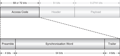
The first part of the access code is a 4 bit preamble which is used to detect the edges of the received data. The preamble is a fixed sequence of either 0 1 0 1 or 1 0 1 0, depending on the value of the first bit of the synchronisation word2 (sync word) so as to form a known 5 bit sequence. This gives the DC thresholding and clock recovery circuitry only 5 μs to create a reliable clock signal with which to sample and clock in the remainder of the data. If a payload is following on, then the last part of the access code is a four bit trailer, and, similar to the preamble, this may be used to perform more accurate DC thresholding and clock recovery. However, by this stage, the radio must already be settled to get good access code matching performance in a real-world environment.
2The preamble is 0101 for a sync word which starts with a 0, and 1010 otherwise. The trailer is 1010 for a sync word which ends with a 0, and 0101 otherwise.
The synchronisation word (see Figure 4–11) is formed from the 24 bit Lower Address Part (LAP) of the Bluetooth device address using an algorithm defined in the Bluetooth specification. First, the algorithm appends a predefined 6 bit sequence known as a Barker sequence to the LAP to improve the autocorrelation properties of the sync word. This is then XOR’d with bits 34 to 63 of a full length, 64 bit PN sequence P[63:0]. The resulting 30 bit sequence is then encoded with a (64, 30) BCH (Bose-Chaudhuri-Hocquenghem) block code to yield a 34 bit parity word. The remaining bits, 0 to 33 of the PN sequence, are then XOR’d with the 34 bit BCH parity word to derive the final coded parity word. The second XOR’ing stage removes the cyclic properties of the block code from the result.
Figure 4–11 Synchronisation word structure.

A more complete derivation is given in the specification. However, the significant point is that the 34 bit BCH parity word is the key element of the sync word and exhibits very high auto-correlation and very low co-correlation properties. Thus, when a device is correlating against its expected sync word, it will find a strong peak exactly where the reference sync word and received sync word line up. Other nonmatching sync words will feature no such peak and indeed will have a low average, much less than 50% of the maximum 34 possible. The remainder of the sync word is constructed from the actual LAP and Barker sequence used to generate the parity word and, as such, is less useful—the LAP in particular. Two devices’ LAPs may differ in only one bit; the two parity words, however, will be quite different, while the remainder of the sync words will be very similar.
It is a topic of debate in the industry that some of the space occupied by including the whole LAP may have been put to better use as an extended preamble to ease the DC thresholding and clock recovery problems in the radio. Oversampling the access code can mitigate this problem by allowing clock recovery to extend into the access code region.
The receiving device continually shifts data into a correlator which does a complete 64 point correlation against the reference or expected sync word. A match indicates that this packet is intended for the receiving device, and it will continue to receive the packet header; otherwise, after the uncertainty window has passed, the radio can be shut down to conserve power. In this way, a Slave will only receive packets which are transmitted by its Master within the Master’s own piconet. If two piconets are close by, each set of Slaves will only receive packets on its own piconet, which has that piconet’s sync word. The point in time at which the correlator match occurs is crucial, as this is when the Master is exactly 68 μs into its slot. This allows the Slave to readjust its own subslot timing to match up with the Master to within 1 μs. Similarly, a Master will only receive from its own Slaves.
4.6.1.1 Access Code Types. There are four distinct access codes, which might be in use at any one time, as follows:
- Channel Access Code (CAC)—The CAC is derived from the Master’s LAP and is used by all devices in that piconet during the exchange of data over a live connection.
- Device Access Code (DAC)—The DAC is derived from a specific device’s LAP. It is used when paging a specific device and by that device in Page Scan while listening for paging messages to itself.
- General Inquiry Access Code (GIAC)—The GIAC is used by all devices during the inquiry procedures, as no prior knowledge of anyone’s LAP will exist. The GIAC is fixed in the specification as 0x9E8B33.
- Dedicated Inquiry Access Code (DIAC)—There is a range of DIACs reserved by the specification for carrying out inquiry procedures between a specific set of devices only, i.e., printers or cellular handsets. These use LAPs in the range 0x9E8B00 – 0x9E8B3F. There have not been any definitions of specific DIACs for specific classes of devices as yet, and so the Generic Access Profile (GAP) specification indicates that only the Limited Inquiry Access Code (LIAC) should be used. This is the only currently defined DIAC and is based on the LAP 0x9E8B00. Two devices may use the LIAC on a temporary basis only where user intervention has caused them to attempt to discover and be discovered by each other.
4.6.2 Packet Header
The packet header in Figure 4–12 contains control information associated with the packet. In total, the header contains 18 bits of information, which are protected by a Forward Error Correction (FEC) code of 1/3. This encoding replicates the data three times so that each bit occupies 3 μs, or 3 bit periods on air. The resulting header is then 54 μs in length. This high level of redundancy and coding overhead is employed because each field is crucial to the correct operation of the link control protocol and thus the link. A CRC field is included to allow the entire packet to be ignored and the link status maintained should any of the contents become corrupted.
Figure 4–12 Packet header structure.
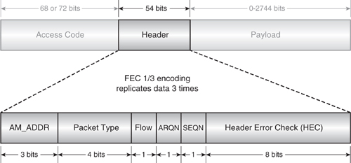
AM_ADDR. During the paging process, the Master will assign an Active Member ADDRess (AM_ADDR) to the Slave. This will then form the connection handle used to address all communications to the Slave and for the Master to differentiate between responses from different Slaves. The 3 bit field is sufficient for seven Slaves. An AM_ADDR of zero corresponds to a broadcast packet from the Master to be received by all of its Slaves. The FHS is an exception in that it is not a broadcast packet but can carry an AM_ADDR of zero. This is because no AM_ADDR has been assigned at the instant the FHS packet is first transmitted.
Packet Type. The packet type defines which type of traffic is carried by this packet (SCO, ACL, NULL or POLL), the type of error correction used for the payload, and how many slots the payload will last for.
Flow. This flag is asserted by a device when it is unable to receive any more data due to its receive buffer not being emptied.
ARQN and SEQN. The ARQN flag is asserted by a device to indicate that the previous reception was successful following validation of the CRC (ACKnowledge or ACK-condition). If, however, the ARQN was lost due to failure of the returned header, then the original sender of the data will assume a Negative-AcKnowledge (NAK) condition and retransmit the first packet again. Each time a new packet is sent, the SEQN (Sequence) flag is toggled. However, in this case, because the packet is resent, the SEQN flag will stay the same and the recipient will see two identical packets where the SEQN flag has not changed. It will then ignore the second and all subsequent packets until the SEQN flag changes. Even if the link is very bad, an ACK will eventually get through and the sequence will move on.
Header Error Check (HEC). The HEC field is simply a CRC function performed on the header represented in octal notation by the generator polynomial 647. It is initialised with either the Master or Slave UAP or DCI, depending on the packet. (DCI is a Default Check Initialisation and is all zeroes.) The HEC allows a recipient to ignore the remainder of a packet following failure of the HEC.
4.6.3 ACL Payload
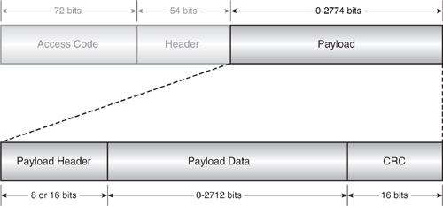
The payload field of all ACL packets (Figure 4–13) is split into three parts; the payload header, the payload data itself, and the Cyclic Redundancy Check (CRC) field.
Figure 4–13 ACL payload structure.
4.6.4 ACL Payload Header
The payload header field contains the following logical link control information (see Figure 4–14):
Figure 4–14 ACL payload header structure.
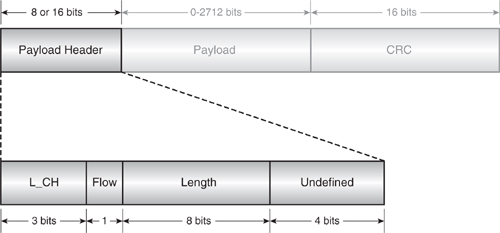
- The L_CH (Logical Channel) field—Indicates whether this payload is the start or continuation of an L2CAP message (since L2CAP messages may last several ACL packets) or an LMP message (which is carried only in single-slot ACL packets).
- The flow flag—Controls data transfer at the L2CAP level.
- The length field—Details the length in bytes of the payload data itself.
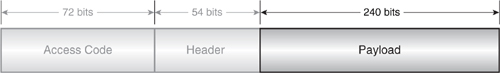
4.6.5 SCO Packet Structure
SCO packets (Figure 4–15) share the same access code and header as ACL packets, though the flow, ARQ, and SEQ fields are redundant since flow control and retransmission do not apply to SCO links. A CRC field is also absent. The size of the payload is fixed at 30 bytes (240 bits), with a source data size of 10, 20, or 30 bytes, depending on the packet type which selects the FEC ratio to use (1/3, 2/3, or none).
Figure 4–15 SCO packet structure.
4.6.6 Mixed SCO / ACL Packet Structure
A special case of SCO is the DV packet in Figure 4–16, which, like SCO packets, must be sent at regular intervals. The voice field is only large enough to send 10 byte, HV1-style data which is not FEC-protected. Similar to normal SCO packets, the voice field can not be retransmitted. However, the data field is protected with 2/3 FEC coding, a CRC field, and the usual flow, ARQ, and SEQ flags. Retransmission of the data field is possible, and this will occur alongside the ongoing SCO transmission in the voice field.
Figure 4–16 DV packet structure.
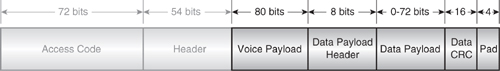
The data payload field will carry up to 9 bytes (72 bits) of data, and as such, the data field is closest to a DM1 packet in nature, although it is almost half the bandwidth. The pad field at the end of the packet is appended, as required, to the source data to ensure it is a multiple of 10 bits prior to FEC encoding.
4.6.7 Special Packets—ID, NULL, POLL, and FHS
The ID packet consists only of the access code and is used during “preconnection” operation, where a link has not yet been established and the relative timings between devices may be unrelated. The ID packet is a highly robust signalling mechanism, since the only information it carries is the access code of the device it is coming from or going to. It is detected and decoded simply by correlating against the desired access code.
The NULL packet consists only of the access code and packet header and is used to pass acknowledgment (ARQ) or flow control back to a device following reception of a packet. The NULL packet itself does not require acknowledgement.
This typically occurs during a link when the recipient of a data transfer has nothing to send in return. It must, however, still acknowledge the packet it has received. Indeed, on initial establishment of a link between two devices but in the absence of any data to transfer, the Slave sends NULL packets.
The POLL packet has the same structure as the NULL packet, but whereas the NULL packet does not have to be acknowledged, the POLL packet must be acknowledged whether or not the recipient has any data of its own to return. However, the POLL packet does not itself affect the acknowledgement or retransmission control scheme governed by ARQ and SEQ. The typical use of POLL is by a Master to check the presence of Slaves in a piconet, which must then respond if they are present.
The Frequency Hop Synchronisation (FHS) packet in Figure 4–17 is sent by an inquiry scanning device to an inquirer during the inquiry procedure, by a Master to a Slave during the page procedure and by a device taking over as Master when Master and Slave devices switch roles. In all cases, the FHS packet provides all the information required by the recipient to address the sender in terms of timing, and thus frequency hop channel synchronisation and correct device access code. The contents of the FHS packet are as follows:
Figure 4–17 FHS payload format.
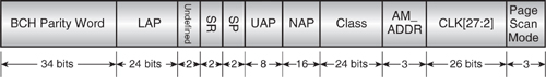
The BCH parity word field contains the key part of the sync word, and, together with the LAP and relevant Barker sequence, it will form the Device Access Code of the sender. Note, some Bluetooth devices always require the BCH parity word, even though it is possible to calculate the correct BCH word to use on-the-fly from the relevant LAP (and some devices do this).
The LAP, UAP, and NAP are the complete 48 bit device address of the sender and are used for different purposes in packet coding and hopping calculation.
SR and SP specify the page Scan Repetition and Scan Period times, respectively, while the page mode field indicates which page mode is used by the sender by default.
The class field indicates which device class the sender belongs to, such as printer, PDA, cellular handset, etc.
The AM_ADDR field indicates the AM_ADDR to be used by the recipient if being sent by a Master during paging or Master/Slave switch, or it must be zero if being returned by an inquiry scanning device.
The CLK field is the native Bluetooth clock of the sender to a slot-pair accuracy, that is CLK[27:2]. This allows the recipient to synchronise its complete clock by calculating the relevant offset and applying this to the native clock. The lower order bits and subslot, (i.e., μs) synchronisation is obtained by the action of the correlator matching against the Master’s DAC (or in the case of a Master/Slave switch, a separate message is sent giving the synchronisation information for the low order bits).
4.7 Packet Types And Packet Construction
Table 4–1 lists all the different packet types and their particular characteristics.
Table 4–1 Packet Type Summary
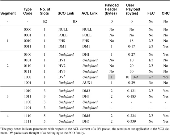
The Segment column splits the different packets into special control packets: single-slot data, 3 slot data, and 5 slot data, respectively. The different ACL packet types trade off more or less FEC coding and shorter or longer packets for lower data throughput with more robustness versus higher data throughput with less robustness. Greater protection against errors is at the expense of data redundancy, while long packets (i.e., Dx3 / Dx5) are more susceptible to an irrecoverable number of burst errors during the longer on-air packet time.
The different SCO packet types simply use increasing error correction to add redundancy and thus robustness. Bluetooth coded audio does not require the data bandwidth which a multi-slot packet would provide.
It is the responsibility of the Link Manager (LM) to monitor the quality and reliability of the link and decide what packet types are appropriate at any given time. Some devices will not support all the packet types, and so at link setup time, some negotiation is often necessary.
Symmetric throughput is obtained by using the same packet types in both directions. However, many applications have asymmetric bandwidth requirements. In general, a link may pass different length packets in one direction, to those passed in the other direction. Indeed, the maximum data throughput of 723.2 kb/s can be achieved with 5 slot packets in one direction and single-slot packets in the reverse direction at 57.6 kb/s. This compares with the maximum symmetric rate of 433.9 kb/s using DH5 packets in both directions.
4.8 Logical Channels
The specification defines five logical information channels which are carried over the physical SCO and ACL links. Although not commonly referred to, they are important in differentiating between the content of the various packets being passed and the information they carry. The channels are as follows:
LC (Link Control)—This is carried via the packet header and consists of the ARQ, SEQ, and associated control data. As described previously, this data is crucial to maintaining and controlling the link.
LM (Link Manager)—This is carried via a dedicated ACL payload and contains LM control data being exchanged between the two LM entities. Typically carried by DM-type packets, the LM channel is indicated by the L_CH = 11 code. Note that the DM1 packet is common to SCO and ACL links. This is to allow LMP messages to be carried over an active SCO link.
UA / UI (User Asynchronous) or User-Isochronous data)—This is carried via the ACL payload and contains L2CAP user data. Fragmentation is handled by the appropriate value of L_CH; 10 for start packets and 01 for continuation packets. Isochronous, though outside the scope of the baseband, will be correctly transported provided that it is timed correctly by entities higher up the stack.
US (User-Synchronous data)—Transparent Synchronous data is carried via SCO channel payloads.
4.9 Channel Coding And Bitstream Processing
Figure 4–18 describes the baseband data flow and how channel coding fits into the overall picture. Since each coding function is carried out on all or part of the data bitstream as it passes through the baseband, we shall also refer to this as bitstream processing.
Figure 4–18 Baseband data flow
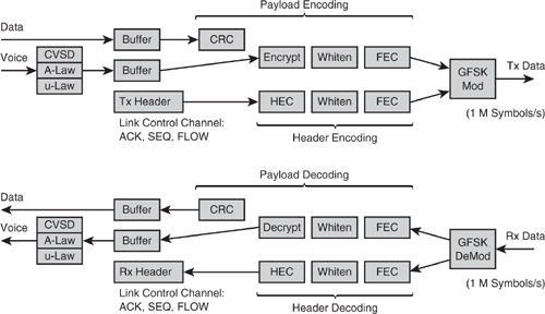
Coding of data before transmission through a carrier medium or channel is important to protect the data against an imperfect channel. Since Bluetooth is only designed to work over a line-of-sight link and the data rates are relatively modest for the signalling bandwidth, the necessary coding is not too complex. The coding applied to the data bit-stream in Bluetooth consists of the following elements:
CRC (Cyclic Redundancy Check) and Header Error Check (HEC) A CRC is performed on all packet headers and on ACL payload data to validate the integrity of the received data. FEC processing has a limited scope for correction and even detection of errors, while a CRC will flag any errors in the data. The 8 bit HEC is calculated over the packet header before applying FEC. The 16 bit CRC is calculated over the payload header and payload. In both cases, the LFSRs are initialised with an appropriate device UAP to provide more dependence on correct addressing to increase robustness to errors.
Encryption The details of encryption are covered separately in the section on security and encryption. The cipher stream, which is sourced by the encryption engine, is simply exclusive OR’d into the bitstream data path.
Whitening or bit randomisation Whitening involves mixing a pseudo-random bit sequence with the data bitstream to randomise the data. This greatly reduces the possibility of long sequences of zeros or ones, or put another way, DC bias. This would cause certain radio architectures (especially those that directly drive Tx data onto the VCO) to drift off channel. It also gives rise to better performance from the receive chain in a radio due to the avoidance of offsets which might otherwise build up.
FEC (Forward Error Correction) By adding extra “parity” bits created from the input data, a number of bit errors in the data may be detected and corrected. There are three FEC options selected by virtue of the packet type: non, 1/3, and 2/3. The strongest, 1/3 encoding, involves simply repeating each bit three times and is decoded by carrying out a majority function on the receive side. This is sufficient to detect two in every three bits input and to correct one in every three. The packet header uses 1/3 encoding, as the link information contained therein is the most critical part of the packet. 2/3 FEC is a (15, 10) shortened Hamming code typically implemented as an LFSR. For every 10 bits of data which pass through, the LFSR is “open circuited” (i.e., the taps removed) and the contents of the five registers are shifted out to form a 5 bit parity value. Thus, for every 10 bits input, 15 bits are output. This protection is sufficient to detect 2 bits in the 10 bit input and to correct 1 in every 10. Padding after the CRC is required to ensure the input data is a multiple of 10 bits in length.
Whitening and the HEC are applied to all packets with at least a header. FEC and CRC are only applied depending on the packet type, as shown in Table 4–1, and FEC may be traded off against link bandwidth as we have already discussed.
The ordering of bitstream processes is important. Considering the transmit path shown in Figure 4–18, first the CRC or HEC is attached to provide validation of the raw data. Then, the whitening is applied to randomise the data. Finally, the FEC is performed. The use of whitening before FEC maintains the performance of the FEC process where there is a long sequence of zeros or ones, which is quite likely in user data pay-loads.
SCO data is encoded or decoded by one of the three audio coding schemes and bypasses the CRC stage in both directions, since retransmission of SCO is not possible. The Tx / Rx buffers shown are to allow transmit data to be written and receive data to be read while the bitstream is processing live data. Each link will require its own transmit buffer since any previously transmitted ACL packet may have to be retransmitted much later after several other ACL packets have been transmitted on different links. Thus, the next packet may not be sent, it being replaced in sequence by a retransmission of the old packet. This selection of which buffer to send is under control of the ARQ scheme.
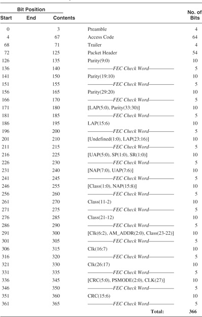
As an illustration of the application of FEC, Table 4–2 lists the complete composition of the FHS packet as transmitted on-air with 2/3 FEC. Note, the order of transmission is Least Significant Bit (LSB) first.
Table 4–2 FHS Packet Composition
4.10 Timebase Synchronisation And Receive Correlation
Now that we have discussed the operation of the overall system timing and have looked at the structure of the various packets, it is useful to understand how a Bluetooth device maintains timebase synchronisation by periodically correlating against the sync word. This is shown in Figure 4–19. Nominally, the window of accuracy expected within Blue-tooth is ± 10 μs or 20 symbols, which as described above requires resynchronisation at least every 800 slots. However, in other circumstances, such as inquiry scan or returning from park mode, this window may be larger.
Figure 4–19 Receive correlator timing.
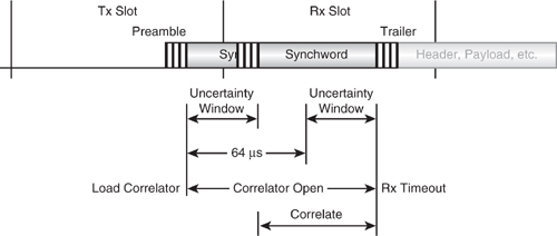
Correlation is carried out against the stored sync word of 64 bits and so the correlator must first shift in the full number of 64 receive bits. This process is started half the uncertainty window before the beginning of the slot. A 64 point correlation is then carried out and compared with a threshold value. Each successive receive bit is shifted in and the correlation repeated until a number (equal to the uncertainty window) of correlations have been made or the threshold value is breached. If the threshold is breached, the access code has been matched; if, on the other hand, the end point is reached, then the correlation has “timed out” and no valid access code was found.
At the point where the correlator matches, two operations must occur:
- An event is signalled to the receive state machine to commence reception.
- A measure of the subslot symbol accurate timing offset between the two devices is made and the complete clock offset updated appropriately to maintain CLK.
The match point is the point at which the last bit of the Master’s transmitted sync word has been received. Either the next bit in 1 μs time (68 bit access code) or the fifth bit in 5 μs time (72 bit access code) will be the start of the packet header. The timing offset between transmitter and recipient is measured at this point. If TMatch is the time in symbol ticks from the start of the recipient’s receive slot to the correlator match point as taken from the current value of the timebase, the offset is TMatch less the sync word length (64) and less the preamble length (4), or TMatch - 68.
The updated CLK and subslot count are applied immediately, and so the following reception of header and payload will be correctly synchronised. If the device is a Slave, then it updates its offsets so as to align with the Master. However, if the device is a Master, each subsequent slot pair will involve a different Slave, each using the Master’s timing. So, although the Master maintains an offset of zero in each case, it must resynchronise its receive process to find the correct start of data following the correlator match.
4.11 Frequency Hopping
Frequency hopping really is at the heart of Bluetooth, and we will see in the next chapter how it forms a fundamental part of the protocol. The hop channel selection function itself is a straightforward mapping algorithm which follows a different sequence depending on the link control state (i.e., inquiry, paging, etc.). It selects a particular sequence depending on parts of the supplied BD address (LAP and UAP). It then indexes through that sequence using the supplied Bluetooth CLK value. Due to the restrictions on channel allocation described in the radio chapter, the algorithm may be truncated to work with only 23 channels in some countries, rather than the usual 79.
The stream of channel numbers generated is passed to the RF subsystem, where they are programmed into the channel synthesiser.
For each of the 79 channels and 23 hop modes of operation, there are four sequences defined as listed below. The following descriptions are specific to 79 channel hop operation and selection is based on the LC state.
(i) Page or Inquiry
This is a fast sequence driven by the half slot clock using 32 equally distributed hops over the full range for transmit. The transmit sequence is split into two “trains”—A and B. The A train contains the 16 frequencies on either side of and nearest to the expected4 page or inquiry scan frequency that the scanning device is listening on. The B train contains the next 16 split on either side of the A train. The result is the sequence that follows:
4For inquiry there is no expected inquiry scan frequency.
f(k-8)…f(k)…f(k+7), f(k+8)…f(k+15), f(k-16)…f(k?9)
where f(k) is the expected channel as defined by CLKE during page. During inquiry, since no estimate exists, the sequence is driven by CLKN of the inquirer and we just start at a random point in the sequence. The correct BD address (or inquiry LAP / UAP) is of course important to provide both units with the same sequence. Over time, the order within the trains is shifted to avoid any constant mismatch.
After two half-slot transmits, the device listens on two half slots, but on frequencies corresponding to two successive page / inquiry response sequence frequencies that would follow from the two page / inquiry frequencies used for transmit. The algorithm is effectively a superset of that used for the response calculation to facilitate this “frequency handshaking” operation.
(ii) Page Response or Inquiry Response
During a response state, the CLKE (page response) or CLKN (inquiry response) input to the selection algorithm is frozen5 at its value when the scanning device correlator fires signalling reception of the ID packet. This ensures that once channel coincidence has been found, it is not lost. The first response is made at the same frequency, but each subsequent transmission is at the next in the page / inquiry sequence, obtained simply by incrementing a counter offset “N” once per slot pair in page response or after each FHS reply in inquiry response.
5Bluetooth V1.1 does not freeze the CLKN input to the selection algorithm as it is pointless.
(iii) Page Scan or Inquiry Scan
This is a very slow sequence, that uses the same BD address inputs as the page / inquiry scheme and thus follows the same sequence but is driven by CLKN bits 15 to 12 and thus hops at 1.28s.
(iv) Connection
Channel hops are produced at a rate of one per slot, except during multislot packets. There is no hop during a multislot packet, although the sequence continues unhindered after the packet. The sequence involves all 79 (or 23) hop frequencies spread equally, but with the maximum distance between each, with the longest possible time interval between repeats. Repeat patterns are not exhibited over a short time period.
4.12 Summary
The baseband is responsible for channel coding and decoding and low level control of the timing and management of the link within the domain of a single data packet transfer. It adds addressing and link control fields to the raw payload data and provides error detection and correction.
Devices exist in two basic modes of operation, either Slave or Master, and communicate between each other in miniature networks known as piconets, which consist of a number of Slaves controlled by a Master. The data links which exist between devices are classified into SCO for time bounded data such as audio and ACL for packet based data.
A number of different packet types exist, and these offer a tradeoff between reliability and data bandwidth.
Bluetooth ensures that devices maintain time synchronisation by repeatedly resynchronising to the Master’s transmissions. Since the frequency hopping algorithm is based on the device clock, this also ensures that frequency hopping is in step.