Take a moment to consider the ease of use that wireless devices provide. The scenario of a wireless notebook or Personal Digital Assistant (PDA) user accessing data network services over a fixed network via a LAN Access Point (LAP) instantly conjures up images of simplicity and ease-of-use. The LAN Access Profile provides the capability of a data terminal (DT) device to wirelessly access the services provided by a LAP. Figure 10-1 and Figure 10-2 show the various scenarios that are supported by this profile.

Figure 10-1. The LAN Access usage model is capable of allowing notebooks or PDAs to behave as DTs, where both devices can access the services provided by the LAN Access Point.

Figure 10-2. In this illustration, a notebook has been configured to behave as a LAN Access Point, while the other notebook behaves as the DT. The DT is now capable of accessing the services of the LAP.
The primary aim of the LAN Access Profile facilitates the support of the networking Internet Protocol (IP) over the Point-to-Point Protocol (PPP), which is a required component of the profile. This subsequently supports other related networking protocols, such as Transmission Control Protocol (TCP) and Network Basic Input/Output System (NetBIOS). There are numerous similarities with the Dial-up Networking (DUN) Profile, and these are explained in the following section.
It is often asked what the differences are between the LAN Access and the Dial-up Networking Profiles. In fact, there is little difference between the two. Both profiles depend upon the Serial Port Profile; both enable an IP stack to be supported and both require a PPP implementation. The subtlety exists in how the Bluetooth link is established. Figure 10-3 shows the components of the modem driver and the modem emulator, which sit within the DT and GW, respectively. Essentially, the modem component completes a direct serial cable connection between the DT and GW, forming a wireless bridge. Whereas the LAN Access Profile provides the direct services of a LAN through a LAP.
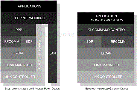
Figure 10-3. The components of the LAN Access and Dial-up Networking Profiles are shown to illustrate the subtle difference. The same applications can be used for both profiles.
The circumstances that arise for the different usages can be best illustrated by considering a user sitting in an office where a fixed [1] access point is readily available and where the user can make use of the services. However, in the DUN instance, a user may use his or her mobile phone to access those same services across a public telephone network. Essentially, the two profiles provide greater flexibility and mobility depending on your situation.
The PPP implementation in both profiles are similar and set out to achieve the same goals of enabling an IP stack, but the LAN Access Profile omits the use of AT commands (see the Dial-up Networking Profile, Chapter 8).
This section considers both existing and future usage models through scenarios that may be typical for the LAN Access Profile. We begin by exploring the existing models where, at face value, the LAN Access Profile provides the wireless ability to make use of a LAN and, in future usage models, we consider alternative means of providing other levels of wireless networking.
Earlier, we touched upon the single, multiple and PC-to-PC scenarios provided in Figure 10-1 and Figure 10-2; these are presently our existing usage models. A single DT is capable of connecting to a LAP and will have its full attention at its disposal. Multiple [2] DTs would inevitably cause the LAP to share its bandwidth resources. Like the single connection, the DT has the ability to utilise the services of the LAP; with multiple DTs, as well as providing the services of the LAP; it would also provide the ability for the DTs to share information with one another.
The other usage model to discuss here is the PC-to-PC scenario. In this instance, we do not necessarily have a DT or a LAP, but we do have two devices that are capable of supporting LAN Access. The scenario is such that DeviceA wishes to connect to DeviceB (there are certainly other profiles, which would also accommodate this scenario); DeviceB takes on the role of LAP and DeviceA takes the role of DT. DeviceA is now capable of exploring the services of DeviceB in the usual manner. For a specific PC-to-PC configuration, support is also offered for an independent connection to a PC that is running a PPP Server; for example, a Microsoft Windows 98 installed PC is bundled with a PPP Server. In order for these two devices to create a successful connection, an exchange of text strings must be performed: CLIENT and CLIENTSERVER.
A LAN Access Point might typically be installed in an area where it is not convenient to either install or continue a cabled network, or it may be installed in an area purely for convenience, such as a conference room. Although, this type of model does provide the image of an embedded device fixed to ceiling or wall, a LAP may take the form of a standalone PC or take a similar form to that of a modem, which may sit alongside or on top of a PC. Here, it has become Bluetooth-enabled and supports the LAN Access Profile. It may then be connected to the LAN or simply offer other resources. The important point here is not to confine our thinking to stereotypical images of what a device should be.
At its core, these models effectively provide the wireless means to connect to a LAN, but there are other numerous applications to be explored.
We have talked about the services of a LAP being provided by an existing cabled infrastructure. It would be possible to imagine that an infrastructure could comprise a series of access points that form the basis of a corporate or public network. In the same way that is currently depicted by the LAN Access Profile, users may now freely walk around an office and maintain the connection to the LAN, thereby achieving a seamless connection to the network. Current limitations of the v1.1 specification would dictate that, for each new access point the user is exposed to, a new authentication and encryption procedure would have to be endured. What is achieved from this new usage model is a wireless infrastructure providing ease-of-installation and mobility.
The general availability and low-cost of an access point would provide users with the potential to access data on-the-go, for example, at the train station or in a hotel. Many manufacturers are already considering this potential. It is possible to provide data services such as this in other public spaces, where the user is not confined to a particular area; Access Point Kiosks (APK) or similar facilities could be introduced. In the same way that we take public telephones for granted, accessing the services of an APK can be made readily available at a charge to the user (the duration of the connection or a one-off charge can be made). These models are not necessarily restricted to future usage scenarios. Our existing usage model is more than capable of providing these services, but the ability to roam from one device to another further simplifies the user experience.
We have seen these public services already in various guises. For example, we can connect to our corporate network and collect email when we are in a hotel using a standard modem, but how often have we spent time searching through our case looking for the correct connector and cable? With Bluetooth applications, we are building on the fundamental philosophy that sparked its creation: cable replacement technology.
The LAN Access Profile provides two new roles: a DT and a LAP. The LAP provides the ability for a DT to connect and to provide its services; this is achieved by running a PPP Server, which transports its packet over RFCOMM. The DT incorporates a PPP Client, again transporting packets over RFCOMM, which in both cases allows it to provide support for an IP stack. Previously, we touched upon the fact that the profile is capable of supporting the range of stereotypical networking protocols; Figure 10-4 demonstrates the architecture of the components that would make up the complete LAN Access model.
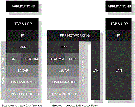
Figure 10-4. The core components of the Bluetooth protocol stack are shown illustrating how the components of the LAN Access Profile are integrated.
During any PPP communication, encryption must be enabled within the Link Manager (LM); any attempt to avoid an enforcement of this operation would result in a failure of connection.
Table 10-1. The list of behavioural characteristics that are typical for this profile.
|
CONFIGURATION |
ROLE |
DESCRIPTION |
|---|---|---|
|
DeviceA |
DT |
A device acting as a DT, which may take the form of a notebook or a PDA. In this particular context, the device is described as initiating the connection with the accepting device. |
|
Initiator |
This configuration describes the device that instigates the original connection or the device that wishes to initiate communication over an existing link. | |
|
DeviceB |
LAP A device that behaves as a LAN Access Point, where |
it manages incoming and outgoing network communication. It is also the party that accepts incoming connections from the DT. |
|
Acceptor |
This configuration describes the process of the device accepting the initiated communication from DeviceA. |
In Table 10-1, clarification is provided with regard to the roles used within the context of this profile. In general, DeviceA represents the initiating party and DeviceB represents the accepting party. The terms are often used interchangeably when describing specific operations in various contexts and are provided here for reference.
The LAP should support additional parameters to configure the user mode operation. The profile supports various scenarios and, as such, the user mode parameter setting can restrict the number of users accessing remote services.
You may remember that a maximum of seven users can simultaneously access the services of a LAP. In Table 10-2, we illustrate the two user modes available to a LAP administrator.
In Figure 10-5, we can see the LAP administrator setting the number of users capable of accessing this service to one and, as such, places the device into a Single-User Mode. Conversely, Figure 10-6 shows the user increasing the number of users capable of accessing the same service, that is, the LAP administrator places the device into Multi-User Mode.
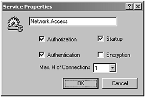
Figure 10-5. The LAP administrator has restricted the number of users to one; the setting has placed the device into a Single-User Mode. (Courtesy of TDK Systems Europe.)
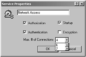
Figure 10-6. The LAP administrator has now increased the number of users capable of accessing the device; this setting has placed the device into Multi-User Mode. (Courtesy of TDK Systems Europe.)
In this chapter, the DT is referred to as DeviceA, or the initiator and the LAP is the acceptor and forms DeviceB. Initially, DeviceA takes the role of master of the piconet, but DeviceB will request a master-slave switch, if it is configured for multi-user mode. We will discuss master-slave switching in more detail later in this chapter.
Table 10-2. The LAN Access Point encompasses additional parameters for its operation. Placing the device into a single or multi-user mode can restrict the number of users accessing the remote service.
|
PARAMETER |
DESCRIPTION |
|---|---|
|
Single-User Mode |
This places the LAP into single-user mode restricting the number of users to one. |
|
Multi-User Mode |
The multi-user mode parameter allows the LAP administrator to set the number of users capable of simultaneously accessing the services of the LAP. |
As soon as the user has the ability to connect and has discovered the availability of a LAP, he or she may now continue to make use of the services it provides. The user may now be able to double-click [3] the LAP icon or right-click its icon to begin the process of connecting to the LAP, see Figure 10-7.
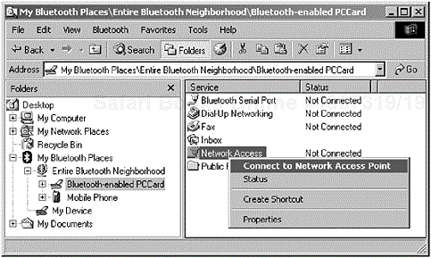
Figure 10-7. Right-clicking the devices icon causes a pop-up menu to appear, offering the ability to connect to the device. In this illustration, we can see the user connecting to a service, which is offering LAN capabilities. (Courtesy of TDK Systems Europe.)
In Section 10.3, Profile Principles, we touched upon the requirement of authentication and encryption. Before a user can access the full services, he or she is required to enter a Bluetooth Passkey. Figure 10-8 shows the user being prompted with a Microsoft Windows dialog box requesting the entry of a passkey. Upon successful entry and authentication, the user may then be required to enter a username or password to fulfill PPP authentication requirements;[2] this would allow further access to the services on the network.
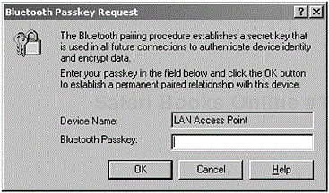
Figure 10-8. The user is requested to enter his or her passkey to authenticate with the LAP device. (Courtesy of TDK Systems Europe.)
It is worth noting that a LAP may offer many services, since its connection to a LAN may be made up of several IP subnets; the subnets, in turn, will offer the user multiple services from that same LAP. The double-clicking or right-clicking operation may expand these services, thus offering the user a greater choice and the initial operation (previously outlined) of connecting would apply to these further expanded services.
Once a connection is established with a LAP and its services are no longer required, the user may terminate the session. In Figure 10-7, we illustrated a user right-clicking the device icon to connect to the device. Similarly, the user may choose to perform the same operation to disconnect.
The profile describes this as termination due to user-intervention. Other forms of disconnection may occur if the quality of service can no longer be maintained by the LAP; an instance of this specific example may occur when the bandwidth is no longer available or the LAN that the LAP is attached to is unexpectedly lost. It is important to remember that the user must be conveyed the appropriate information about their current situation and to be offered a reconnection at a later time.
One other such instance of a terminated connection may occur when a connection is lost due to the DT moving out of radio range from a LAP; we pick this up in the following section.
Current LAP products offer various radio ranges from 10 meters through to 100 meters. With the growing number of Bluetooth-enabled devices in use within an office, there may be some confusion for the user with regard to the radio ranges supported and, as such, if they should walk out of range, the connection is subsequently lost. Advising the user appropriately is paramount and, again, an offer of a reconnection should be made.
The profile covers an instance of this specific operation. It claims to provide the user with the ability to reconnect seamlessly once the DT is within range or other associated disconnection problems are resolved. In addition, it also claims to provide an appropriate warning to the user if their connection is lost. The same method of instigating that initial connection may be used to reconnect to the LAP.
Using the same method of accessing the LAP services, a successful reconnection would occur. This seamless reconnection is achieved due to the fact that both the DT and LAP remember their respective Bluetooth addresses, their passkeys and any previous PPP authentication.
Today, LAP devices usually manifest themselves as embedded devices, secured to a ceiling or placed in a similar location. From an administrator’s perspective, he or she would typically have an initial contact with the device in order to configure and set-up its internal parameters for connection to a LAN. Other parameters such as the Dynamic Host Configuration Protocol (DHCP) configuration, the level of PPP authentication and the number of users can also be defined. The LAP device may also support the use of Simple Network Management Protocol (SNMP [5]) to obtain statistical information about its usage and also the configuration of specific SNMP alerts, which may be triggered during a network-related problem.
The administrator may have at his or her disposal an application, which manages these internal parameters and is connected via a dedicated port on the device itself. The administrator may also have a remote management scheme available via a Hypertext Transfer Protocol (HTTP) interface (see Figure 10-9).
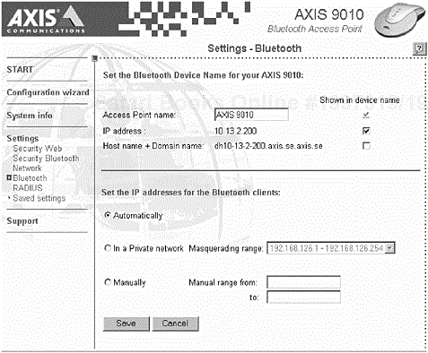
Figure 10-9. This screen shot shows a number of HTTP interface configuration options. (Courtesy of Axis Communications.)
From a distance, the administrator should be able to determine the successful operation through a series of LEDs that are available on the device itself (see Figure 10-10 and Figure 10-11). Many manufacturers offer a series of LEDs that illuminate, according to the activity and operational status.
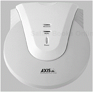
Figure 10-10. One of the many access points widely available today. The Axis’ 9010 Bluetooth Access Point clearly shows a series of LEDs that report the operational status of the device. (Courtesy of Axis Communications.)
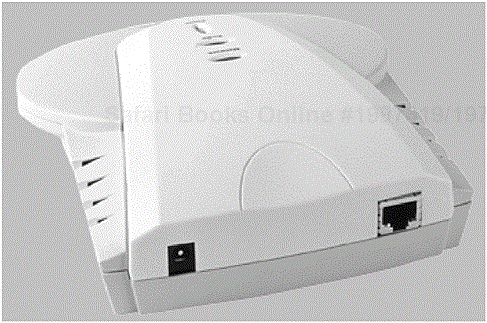
Figure 10-11. In this illustration, the Axis’ 9010 Bluetooth Access Point clearly shows the connection ports available for power and LAN. (Courtesy of Axis Communications.)
In other guises, a LAP may be implemented onto a standalone PC, which itself is connected to a LAN offering users its services. The operational parameters of DHCP configuration and PPP authentication may be managed in a similar manner.
The LAP undertakes a series of events that enable a DT to successfully access its services. Figure 10-12 illustrates these events. As we have already discussed, encryption is an integral component in a successful Bluetooth connection. The LAP is architected in such a way that it refuses to accept any incoming connections from a DT that does not support encryption.
During the connection stage, pairing must occur to form part of the authentication process. The passkey is required prior to any successful connection; we discussed the user interface aspect of this in Section 10.4.1.1, Connecting to a LAP.
There may be several instances when a connection from a DT needs to be refused. The first would be when an incorrect passkey has been entered, where pairing would fail. The second will occur if the PPP authentication fails. The use of the Challenge Handshake Authentication Protocol (CHAP [6]) or the PPP Extensible Authentication Protocol (EAP[6]) is not mandatory, but nonetheless a connection is refused if this is unsuccessful.
Other such instances may be due to the loss of a LAN connection or if the services the LAP wishes to provide are not available. Lastly, a connection should be refused if the LAP has exhausted most of its bandwidth due to the number of users already connected. The user may be advised to reconnect later or may be offered an alternative LAP.
As previously indicated, most LAP devices may take the form of an embedded product; as such, this device is switched on once and left to service the DTs. During the power up sequence, most of the initialisation parameters can be defined. Table 10-3 outlines some of the initialisation parameters that are defined in the profile.
In a similar fashion, a PC or notebook that is configured as a LAP may initialise its power-up parameters when the device is switched on. Alternatively, a PC or notebook may be configured ad-hoc to behave as a LAP, allowing a DT to connect to it. Table 10-4 provides an example list of implementation-specific parameters. [7]
Figure 10-13 illustrates some of the initialisation-specific parameters that are required to configure the LAP.
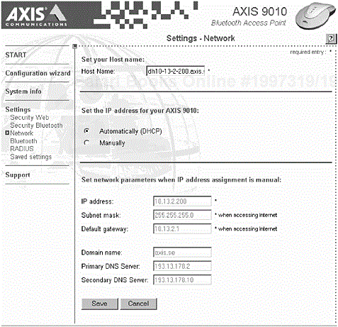
Figure 10-13. A screen shot showing the number of parameters required in order to configure the LAP. (Courtesy of Axis Communications.)
The shutdown sequence of the LAP would ultimately terminate the PPP Server and any active DT connections would be notified of the loss of service.
The DT always initiates a connection with a LAP and it is anticipated that in future profiles a LAP may instigate [8] a connection. There may be several LAPs within radio range offering different levels of service. When performing a service discovery, the range of LAPs will be made available to the DT.
Upon creating an RFCOMM connection, the user is required [9] to enter his or her passkey. Subsequently, the PPP application is then started, requiring the user to enter their username and password. This can be optionally postponed to a later stage in the connection process.
The most common or typical form of termination or disconnection from a DT occurs during user-intervention, that is, the user has requested a disconnection. It is also possible that a failure in the LAN may result in the LAP being unable to continue providing its services to the DT. This section considers the probable causes of termination and how a LAP device should manage such scenarios.
The LAP itself may be connected to a LAN, where other administrators may manage this independently, as such its behaviour is always difficult to predict. The LAP itself should be capable of managing instances where the LAN is lost for whatever reason. The LAP may be handling several simultaneous connections, all of which are uploading or downloading data. During this unexpected loss, both the user and LAP administrator should be informed (the DT user scenarios are covered in Section 10.4.1.3, Losing a connection with a LAP). The administrator would become immediately aware of this, having previously configured his or her installation with an SNMP alert (see Figure 10-14).
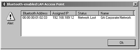
Figure 10-14. An SNMP alert informing the administrator that the LAN service is lost for the network identified.
Table 10-3. An example of initialisation parameters that may be initialised during the power-up sequence of a LAP.
|
PARAMETER |
DESCRIPTION |
|---|---|
|
PPP Authentication |
The LAP administrator determines whether this level of authentication is required and is therefore optional. |
|
PPP Compression |
Again, the LAP administrator determines whether compression should be used. |
|
User-mode |
The number of users allowed to connect to the LAP at any one time determines this mode. For example, setting the user-mode to allow a single user would place the device in single-user mode. Similarly, setting the number of users to two or above would place the LAP configuration into a multi-user mode. |
|
Generic Access |
This parameter refers to the level of support outlined in Section 10.5.1.1, Generic Access. This would determine if specific or all users can make use of its services. |
Table 10-4. An example of implementation-specific initialisation parameters that may be initialised during the power-up sequence of a LAP.
|
PARAMETER |
DESCRIPTION |
|---|---|
|
DHCP |
This set of parameters will allow connecting DTs to have their unique IP address when connected to the LAN. |
|
DNS |
These IP settings allow the correct configuration for routing of data access across the network. |
|
IP |
The LAP itself would need a unique IP address. |
|
SNMP |
Specific configuration for the request of data usage through the use of an SNMP Management Information Base (MIB). The definition of an SNMP alert could be based on statistical information derived from such MIBs. |
The loss of a connection is not restricted to infrastructure related issues. There may be a large demand on the access point, which restricts the Quality Of Service (QoS). The bandwidth itself may not be sufficient and one DT may make extraordinary demands, resulting in a poor QoS for other connected DTs. In the same way that an SNMP alert is generated to inform of networking issues, it could be generated to inform the administrator of performance issues.
Once a connection has been established and data has been transferred, there may be an occasion where the DT device has been taken out of range of the LAP. The DT itself has not made a formal request to terminate the session but, as far as the LAP is concerned, it is still connected; this inevitably inhibits other users from making use of the LAP services.
Both the DT and LAP need to be informed if such a connection has been unexpectedly lost. If the DT moves back into range with the LAP, a seamless reconnection [10] can occur, that is, the LAP and DT may “remember” one another. This can be accomplished because they both store the user’s passkey, link key, user name and password.
In our previous discussion, we covered aspects of existing and future usage models and their respective user expectations. In the following sections, we take an opportunity to explore in greater depth the dependencies that make up this profile. In Figure 10-15, we provide a conceptual illustration representing the dependencies that make up the LAN Access Profile; the areas that are shaded are relevant to this profile. As you can see, the profile depends upon the basic functionality offered to us by the Generic Access Profile, Chapter 2, the Service Discovery Application Profile, Chapter 3 and the Serial Port Profile, Chapter 6. We will discuss, in turn, the basic requirements of these dependent components and any deviations that may occur from the basic functionality originally offered to us.

Figure 10-15. The dependent components of the Bluetooth protocol stack that make up the LAN Access Profile. The areas that are shaded are relevant to this profile.
This section also considers the external components or other dependencies that are not shown in Figure 10-15, but are required for a product to claim conformity. The LAN Access Profile is structured in a manner that determines the level of support from the Bluetooth core protocol layers; as such, the sections are laid out with the particular layer reference in mind.
The LAN Access Profile relies upon the capabilities provided by the Generic Access Profile, Chapter 2. You may recall that a level of basic functionality is achieved through establishing a set of rules and procedures. The behaviour of such devices is governed by simple rules that relate to their connectivity, discoverability and common characteristics at the user interface level, with some additional emphasis provided for security. It is these rules and procedures that are used to establish commonality between products, which will ultimately achieve a cohesive user experience. We will now revisit the behavioural aspects of Bluetooth-enabled devices as outlined by the Generic Access Profile.
Table 10-5. The core set of procedures as required by most profiles.
|
PROCEDURES |
DESCRIPTION |
|---|---|
|
Discoverability Mode |
This mode prescribes the overall discoverability of a device, allowing it to be placed into a non-discoverable, limited, or general discoverable mode. The mode would allow devices to become generally available to other users or it can be restricted to personal use. |
|
Connectability Mode |
When determining a baseband connectable state, this mode is used to place a device into a connectable or non-connectable mode. |
|
Pairing |
Pairable and non-pairable modes are used to realise the security aspects when operating or intending to use a device. A device may require authentication and, as such, the user would be required to enter a Bluetooth Passkey. The pairing procedure starts the link key generation process, which in turn allows authentication to take place. |
In Table 10-5, the basic set of procedures is illustrated, identifying functional expectations which, in turn, govern its operation. These procedures help determine the context in which the device would operate. For example, a device may wish to be discoverable for a period of time or it may require a level of security that differs from one device to another depending upon the services it is capable of offering.
In Table 10-6, we consider the specific set of operations that are required for this profile. In the table, you will notice features are marked with M (Mandatory), O (Optional), X (Excluded), C (Conditional) and N/A (Not Applicable). These will determine what is expected from the features of the Generic Access Profile.
Security is an important aspect for Bluetooth-enabled devices. Table 10-7 identifies the security requirements for this profile. You will also notice that these features are marked in a similar fashion to our previous table. You may remember from the Generic Access Profile, Chapter 2, that Security Mode 1 is a non-secure mode where Bluetooth-enabled devices will never initiate any security procedures; whereas Security Modes 2 and 3 initiate different levels of security procedures at various stages of connection establishment. In this instance, the profile mandates that support should be provided for at least Security Mode 2 or 3.
Table 10-6. The illustration shows specific modes of operation that this profile depends upon to realise its compliant implementation.
|
MODES |
DT |
LAP |
|---|---|---|
|
Non-discoverable |
X |
O |
|
Limited Discoverable |
X |
X |
|
General Discoverable |
X |
M |
|
Non-connectable |
X |
O |
|
Connectable |
X |
M |
|
Non-pairable |
X |
O |
|
Pairable |
X |
M |
In our final consideration of the basic rules and procedures that are required from the Generic Access Profile, the idle mode procedures outline behavioural characteristics when DeviceA chooses to initiate them against DeviceB. The procedures that are listed in Table 10-8 provide a clear indication of how a device should operate when performing such an activity. Let us take our bonding procedure as an example. The term bonding is very much associated with the pairing process; however, bonding occurs when the user has the intent to initiate a trusted relationship with DeviceB.
With this intent, the user is prompted to enter a Bluetooth Passkey which, in turn, instigates the pairing process, that is, the generation of the link keys, where subsequent authentication can then occur. In summary, we realise that there are a specific set of events associated with a procedure. In the Generic Access Profile, Chapter 2, we both presented examine how each procedure is conducted.
The mechanism for providing device discoverability is the provision of a well structured FHS packet, which is shown in Figure 10-16. This packet is used to identify the remote device, where information such as Bluetooth Device Address (BD_ADDR) and clock offsets is determined.

Figure 10-16. The structure of the FHS packet used only for reference to illustrate the position of the CoD structure.
Table 10-7. The illustration shows specific security procedures that this profile depends upon to realise its compliant implementation.
|
PROCEDURE |
DT |
LAP |
|---|---|---|
|
Authentication |
M |
M |
|
Security Mode 1 |
M |
M |
|
Security Mode 2 |
C |
C |
|
Security Mode 3 |
C |
C |
Table 10-8. The illustration shows specific behavioural procedures that this profile depends upon to realise its compliant implementation.
|
PROCEDURE |
DT |
LAP |
|---|---|---|
|
General Inquiry |
M |
N/A |
|
Limited Inquiry |
N/A |
N/A |
|
Name Discovery |
M |
N/A |
|
Device Discovery |
M |
N/A |
|
Bonding |
M |
M |
You may also notice from this packet that the Class of Device (CoD) field is provided. This information is relayed to the user interface which, in turn, provides common characteristics about discovered devices. The CoD is used during the discovery mechanism to learn more about the type of device and what it may be capable of providing. This structure of information is depicted in Figure 10-17 and is made up of 3-bytes (or 24-bits). The following sections now consider the LAN Access attributes, which will ultimately make use of the Service, Major, and Minor Device Class fields.

Figure 10-17. The structure of the CoD, illustrating the Minor Device, Major Device and Service Class fields and their respective lengths.
This high-level form of defining a Bluetooth device identifies where in the Service Class field the LAN Access Profile resides (see Table 10-9) which, in turn, determines the category of service. Here, the category of service falls within Networking.
This high-level form of defining a Bluetooth device identifies where in the Major Device Class the LAN Access Profile resides (see Table 10-10) which, in turn, determines the major class grouping. Here, the category falls within LAN Access Point.
The Minor Device Class in this profile is used to convey further context for the setting within the major class grouping. Here, the bits are set to reflect the utilisation of the LAN Access Point. Table 10-11 lists the values for the load ratio, but no standard formula is used to calculate them. Manufacturers are encouraged to adopt a similar mechanism to report this utilisation.
In an area with multiple LAPs, the DT should make use of the service with the lowest utilisation or, in other words, the LAP that is capable of providing the best bandwidth (assuming that the services available are similar). For completeness, Table 10-12 provides the remaining lower bits that form the minor device class.
In the Service Discovery Application Profile, Chapter 3, we introduced the characteristics of the mechanisms used to retrieve service information from a remote device. Typically, a client will initiate inquiry and discovery procedures as outlined in our previous section, to learn of the devices in radio range. A client can then make use of an application, which embodies the functionality of the underlying Service Discovery Protocol (SDP). The Service Discovery Application (SrvDscApp) uses an SDP Client to instigate a request to the remote device where the SDP Server will respond. As such, the DT and LAP must employ the use of an SDP client and server respectively, as illustrated in Table 10-13.
Protocol Data Units (PDUs) are used to instruct the SDP server to undertake browsing procedures and to retrieve service record information about its services. You may recall that these PDUs carry payloads about requests containing AttributeIDs and AttributeValues describing what exactly is being sought. As previously discussed, the client and server operate a request and response paradigm. SDAP will construct PDUs containing information relating to the AttributeID and AttributeValues, which in turn instruct the server to carry out its operation. The various request and response PDUs that are required are shown Table 10-14, where features indicated are described as mandatory (M), optional (O) and excluded (X).
Table 10-9. The Service Class categorisation for the LAN Access Profile.
|
SERVICE CLASS | |||||||||||
|---|---|---|---|---|---|---|---|---|---|---|---|
|
23 |
22 |
21 |
20 |
19 |
18 |
17 |
16 |
15 |
14 |
13 |
Bit # of CoD |
|
0 |
0 |
0 |
0 |
0 |
0 |
1 |
0 |
0 |
0 |
0 |
Networking |
Table 10-10. The Major Device Class for the LAN Access Profile.
|
MAJOR DEVICE CLASS | |||||
|---|---|---|---|---|---|
|
12 |
11 |
10 |
9 |
8 |
Bit # of CoD |
|
0 |
0 |
0 |
1 |
1 |
LAN Access Point |
A service record is maintained for each service a device is capable of supporting and, as such, a Service Record Handle is created to uniquely identify this. The ServiceRecordHandle is a 32-bit unsigned integer and is stored on the SDP server. The service record shown in Table 10-15 identifies a LAP device and provides a list of AttributeIDs, which ultimately would identify the service for the LAN Access Profile. A minimum of two attributes are required to make a service record; these are ServiceRecordHandle and ServiceClassIDList, which it must contain at least one UUID.
Table 10-11. The 3-bit upper area of the minor device class that depicts the utilisation of the LAN Access Point.
|
MINOR DEVICE CLASS | |||
|---|---|---|---|
|
7 |
6 |
5 |
Bit # of CoD |
|
0 |
0 |
0 |
Fully Available |
|
0 |
0 |
1 |
1 to 17% Utilised |
|
0 |
1 |
0 |
17 to 33% Utilised |
|
0 |
1 |
1 |
33 to 50% Utilised |
|
1 |
0 |
0 |
50 to 67% Utilised |
|
1 |
0 |
1 |
67 to 83% Utilised |
|
1 |
1 |
0 |
83 to 99% Utilised |
|
1 |
1 |
1 |
No Service Available [11] |
[11] In this instance, the user should either be informed of the unavailability of the service (and be asked to try again later) or offered other similar services from other LAPs within radio range. | |||
Table 10-12. The 3-bit lower area of the minor device class for the LAN Access Point.
|
MINOR DEVICE CLASS | |||
|---|---|---|---|
|
4 |
3 |
2 |
Bit # of CoD |
|
0 |
0 |
0 |
Unclassified |
|
0 |
0 |
1 |
Range |
When browsing for services on the remote device, a local device constructs a search pattern using a Universally Unique Identifier (UUID). A UUID is a 128-bit value, which has been shortened for use within Bluetooth. The shortcut has been provided by first establishing a Bluetooth Base UUID, which we discussed in the Service Discovery Application Profile, Chapter 3.
The UUIDs that have been presented are aliases and take the form of what is referred to as a 16-bit UUID or a 32-bit UUID but, in turn, they should all refer to the 128-bit notation. These UUIDs have been assigned and can be referenced in the Bluetooth Special Interest Group, Bluetooth Assigned Numbers, v1.1, February 2001. For the search pattern to be successful, they all need to be converted to the 128-bit notation, since they will all be compared at this range. An arithmetic conversion algorithm is used to construct the 128-bit value.
Table 10-16 summarises the service class UUIDs used to identify the particular profile in use. This also correlates with the identification of the device during a device discovery procedure, as previously outlined in Section 10.5.1.1, Generic Access.
As part of the service record, the identification of the dependent underlying protocols are also identified. The local device retrieves this information, where it can fully understand the exact requirements needed to fulfill the service. The LAN Access Profile is dependent on the protocols as shown in Table 10-17, which also shows their associated UUID values.
In the Serial Port Profile, Chapter 6, we introduced the conceptual and functional nature of RFCOMM and how it provides an emulated serial port presence. Several distinctions were made between the various types of applications. The purpose of making these distinctions was to enable clarification and understanding of RFCOMM’s composition. In this particular application context, the creation of an emulated serial port would be transparent to the user. The LAN Access Profile is dependent upon the operation of the Serial Port Profile and, as such, is required to establish an emulated serial port as part of its communication link with the remote device.
Table 10-13. As a minimum, the local device must support the use of a client application and the remote device must support the use of a server.
|
FEATURE |
DT |
LAP |
|---|---|---|
|
SDP Client |
M |
X |
|
SDP Server |
X |
M |
Table 10-14. The list of PDUs that are required for the operation of the LAN Access Profile.
|
PDU |
DT |
LAP |
|---|---|---|
|
|
X |
M |
|
|
M |
X |
|
|
X |
M |
|
|
M |
X |
|
|
X |
M |
|
|
O |
X |
|
|
X |
O |
The term cable replacement application was introduced in our earlier chapter and distinguishes between the different scenarios available. It refers to specific Bluetooth applications that create implicit emulated serial ports, which remain transparent to the user to complete the creation of a communications link.
Specific detail has been provided to illustrate how data is communicated over an emulated serial port connection, where a Data Link Connection (DLC) is established between two peer devices, namely DT and LAP. We have also looked at the fields that make up our service record for this profile. The ProtocolDescriptorList field is used to describe the set of protocols that the profile intends to use and, as such, the RFCOMM protocol identifier contains a parameter, which contains the Server Channel number.
The Server Channel is used in combination with a Data Link Connection Identifier (DLCI), which is then used to uniquely identify the active DLC. This connection is then mapped onto a connectionless orientated L2CAP Channel Identifier (CID).
In this section we highlight the specific features that are required to realise a compliant LAN Access Profile. Table 10-18 and Table 10-19 illustrate the features or capabilities that are expected from the Serial Port Profile.
The use of the RLS command is encouraged to keep peer devices informed of any state change. In one such instance, an emulated serial port may interface to a Type II application (physical serial port), where overruns or parity errors may occur. An application that makes use of RS232 port configuration parameters should expose these settings through an appropriate Application Programming Interface (API) function; this is of particular relevance when interfacing to Type II applications.
Table 10-15. The list of mandatory and configurable items that make up this profile’s service discovery record.
|
ATTRIBUTE |
DESCRIPTION |
|---|---|
|
|
With an |
ServiceClassIDList ServiceClass0 |
With an |
ProtocolDescriptorList
  Protocol0
  Protocol1
ParameterFor1 |
With an |
BluetoothProfile
DescriptorList
  Profile0
ParameterFor0 |
With an |
|
|
With a base |
|
|
With a base |
|
|
With an |
|
|
With an |
Table 10-16. The service class that matches a corresponding profile. This correlates with our previous Generic Access section.
|
CLASS |
UUID |
|---|---|
|
|
|
Table 10-17. The list of protocols that are used in this profile. Their associated UUID values are also shown.
|
PROTOCOL |
UUID |
|---|---|
|
|
|
|
|
|
Table 10-18. The set of capabilities that are required from the initiating party, denoted here by the DT device.
|
PROCEDURE |
DT |
LAP |
|---|---|---|
|
Initialise an RFCOMM Session |
M |
X |
|
Terminate an RFCOMM Session |
M |
M |
|
Establish a new DLC Connection |
M |
X |
|
Disconnect a DLC Connection |
M |
M |
|
Emulate RS232 Control Signals |
C |
C |
|
Transfer Data |
M |
M |
|
Test Command |
X |
X |
|
Flow Control |
C |
C |
|
RLS |
O |
O |
|
PN |
O |
O |
|
RPN |
O |
O |
The L2CAP layer provides transparency for the upper-layers of the stack from the layers typically found within the host controller. L2CAP payloads are passed to the Host Controller Interface [12] (HCI), which is then subsequently passed onto the Link Manager Protocol (LMP). The range of upper-layers, which include RFCOMM, SDP and the Telephony Control Protocol Specification (TCS) all make use of the capabilities offered to us by L2CAP. Its primary role is to provide protocol multiplexing, allowing numerous simultaneous connections to be made, and also providing the ability for segmentation and reassembly. This refers to the ability to manage large payloads in the applications, which may need to be fragmented into smaller payloads for the lower-layers to manage. These are then transmitted over the air-interface. Finally, the L2CAP layer exchanges QoS information, ensuring that sufficient resources are available and that both Bluetooth devices are attaining the best service.
In Table 10-20, we summarise the broad capabilities that are expected from L2CAP. In the table, you will notice features are marked with M (Mandatory), O (Optional), X (Excluded), C (Conditional), and N/A (Not Applicable); these will determine what is expected from the features at the L2CAP layer.
Table 10-19. The set of capabilities that are required from the responder party, denoted here by the LAP device.
|
PROCEDURE |
DT |
LAP |
|---|---|---|
|
Initialise an RFCOMM Session |
X |
M |
|
Terminate an RFCOMM Session |
M |
M |
|
Establish a new DLC Connection |
X |
M |
|
Disconnect a DLC Connection |
M |
M |
|
Emulate RS232 Control Signals |
M |
M |
|
Transfer Data |
N/A |
N/A |
|
Test Command |
M |
M |
|
Flow Control |
M |
M |
|
RLS |
M |
M |
|
PN |
M |
M |
|
RPN |
M |
M |
Table 10-20. The illustration shows specific procedures that this profile depends upon to realise its compliant implementation.
|
PROCEDURE |
DT |
LAP |
|---|---|---|
|
Connection-orientated Channel |
M |
M |
|
Connectionless Channel |
X |
X |
|
Connection Establishment |
M |
M |
|
Configuration |
M |
M |
|
Connection Termination |
M |
M |
|
Echo |
M |
M |
|
Command Rejection |
M |
M |
|
Maximum Transmission Unit |
M |
M |
|
Flush Timeout |
M |
M |
|
Quality of Service |
O |
O |
In Table 10-20, we have identified that Connection-Orientated Channels are mandatory, whereas Connectionless Channels are excluded; this type of channel is aimed at broadcasting, where all devices may be targeted. L2CAP uses PDUs to transport connection, signalling and configuration options, which will be discussed in a moment. The higher layers of the Bluetooth protocol stack will instigate a connection with L2CAP using the L2CA_ConnectReq request packet, where the corresponding result is contained within the L2CA_ConnectRsp response packet. An L2CA_ConnectRspNeg negative response packet is used to denote a response, where the connection with the remote device was unsuccessful. Since our profile resides above L2CAP and employs its services, we are only concerned with the upper protocol layer of L2CAP. This higher functionality is offered to us through a series of L2CAP events and is denoted through the prefix L2CA_ (see Table 10-21).
When creating an L2CAP connection between two devices, a Protocol/Service Multiplexor (PSM) value is used to denote the higher-layer protocol that is using the connection. Table 10-22 identifies these values and the corresponding protocols they represent. The value of 0x0003 (RFCOMM) is used for this profile.
When establishing communication with a remote device, a signalling channel is created and reserved for use during connection, disconnection and configuration of subsequent L2CAP connections. A channel is used to describe the communication and data flow that exists between L2CAP entities. Table 10-23 illustrates the range of CID used to identify the channel type. As we can see in Table 10-20, Connection Establishment and Termination is mandatory in the local device, although the remote device may be capable of initiating and terminating a connection to the local device. The L2CA_DisconnectReq request packet is used to terminate the connection with the remote device and an L2CA_DisconnectRsp response packet is used to ascertain the result of the termination. All disconnection requests must be completed successfully. The support of Configuration is shown as mandatory and we will discuss these specific options in more detail in the following section. Finally, Echo and Command Rejection are both mandatory for a compliant LAN Access Profile.
Table 10-21. The range of prototypes used to illustrate how L2CAP is architected and how interaction between higher- and lower-layers is achieved. For this discussion, our concern here is with the higher-layer.
|
PROTOTYPE |
DESCRIPTION |
|---|---|
|
|
This prefix prototype is used to denote the higherlayer interaction, typically used by RFCOMM, SDP, and TCS. |
|
|
This prefix is used to denote peer-to-peer signalling interaction of L2CAP entities. |
|
|
Finally, this prefix denotes lower-layer interaction, where L2CAP interfaces with the LMP layer. |
In establishing a connection with the remote device, the channel is subject to configuration and the higher-layer prototype L2CA_ ConfigReq request packet is used to carry configuration requests. Its associated response is contained within the L2CA_ConfigRsp packet. An L2CA_ConfigRspNeg packet is used to denote a negative response during configuration where, for example, the suggested Maximum Transmission Unit (MTU) is too large. In Table 10-20, we have identified that the MTU and Flush Timeout parameters are mandatory, whereas the QoS is optional.
The default MTU setting for the signalling channel is 48 bytes, whereas other channels may be capable of transferring larger payloads. Essentially, the MTU determines the size of payloads that are capable of being exchanged between two devices. During configuration, the local device will inform the remote device that it is potentially capable of accepting larger payloads. If the remote device is unwilling to accept a larger MTU, then the local device is informed with the response contained within the L2CA_ConfigRspNeg packet.
When L2CA_ request and response packets are being exchanged, the Flush Timeout parameter is used to determine how long the local device is prepared to continue to transmit an L2CAP fragment before it gives up; the packet is subsequently flushed or, in other words discarded. The suggested Flush Timeout value is sent during the L2CA_ ConfigReq request packet. However, if no value is set then the default value is used. The LAN Access Profile uses the default value of 0xFFFF.
Table 10-23. The CIDs that are used to represent the logical channel.
|
CID |
DESCRIPTION |
|---|---|
|
|
Null |
|
|
Signalling Channel |
|
|
Connectionless Reception Channel |
|
|
Reserved |
|
|
Dynamically Allocated |
As we have already mentioned, the QoS configuration is optional. If it is used during an L2CA_ConfigReq request, then the best effort service is established as a default. The available services that support an L2CAP channel are shown in Table 10-24. However, if the QoS service is set at Guaranteed, then parameters such Token Rate, Token Bucket, Peak Bandwidth, Latency and Delay Variation, are used to determine an acceptable guaranteed service, where the L2CA_ConnectRspNeg will indicate that these values are unacceptable. These parameters are then subject to further negotiation.
The LM layer sits between the HCI and the Link Controller (LC), although on a hostless system the LM will have direct interaction with L2CAP. It accepts commands from HCI and translates them into operations for the LC, where Asynchronous Connectionless (ACL) and SCO links are created and established. It is during this stage of ACL and SCO establishment that a master-slave switch would be performed as governed by the requirements of this profile. The LM is also responsible for placing the device into a low-power mode, which includes hold, sniff, and park.
In providing general error management, devices that operate mandatory procedures during interoperability must either acknowledge support or inform the initiator why the procedure failed. The LMP_Detach PDU is used to inform the device of the error that occurred. Typically, the reason unsupported LMP feature (0x1A) is reported (see Appendix A).
The LM may optionally make use of multi-slot packets for both the LAP and DT devices. The behaviour of a LAP configured for single-user and multi-user modes should adhere to the master-slave switch operation, as we will discuss.
Table 10-24. The range of service definitions that are used during QoS.
|
SERVICE |
DESCRIPTION |
|---|---|
|
No Traffic |
This indicates that the channel will not be sending any traffic and, as such, any parameters can be ignored. |
|
Best Effort |
This default value attempts to achieve a minimum service with the local remote device, where no guarantees are offered. |
|
Guaranteed |
With this service definition, we indicate that we wish to achieve the maximum bandwidth permitted. This is, of course, subject to the nature of a wireless environment. |
Table 10-25. A feature that is not supported and is part of the requirement for the LAN Access Profile has a specific set of reasons available at the LMP level.
|
FEATURE |
REASON or ERROR |
|---|---|
|
Encryption Disabled |
Host Rejected due to Security Reasons |
|
LAP Switched to Master when configured for Multi-user Mode |
Unspecified Error[13] |
|
Number of Users are at its configured[14] maximum |
Other End Terminated Connection: Low Resources |
[13] This specific error would not necessarily help the user. The error Unsupported Feature may be offered with a possible explanation as to why the connection failed. [14] The LAP administrator is capable of setting the number of users from one to seven. | |
It is clear during the LM stage that several failures of connection are made evident if the DT fails to endorse the pairing process—specifically, if it is unable to provide encryption on the baseband connection or if there is a clear failure to perform the master-slave switch operation, for eample when it is configured for multi-user mode.
Table 10-25 provides a list of errors that are reported at the LM level, which should, in turn, ultimately inform the user of the reason for the connection failure. This places the user in a position where he or she can rectify the specific problem.
In the next section, we take an opportunity to explore the dependencies that make up the LAN Access Profile. We provide a narrative of the capabilities that are expected at this level. In Table 10-26, we identify the capabilities that are required from this layer and in the following subsections discuss the specific procedures in more detail.
Table 10-26 summarises the broad capabilities that are expected from the LM. In the table, you will notice procedures are marked with M (Mandatory), O (Optional), X (Excluded), C (Conditional) and N/A (Not Applicable); these will determine what is expected from the procedures at the LM. The table includes a set of deviations that the profile includes, which are above the common set of procedures expected at LM.
Table 10-26. The change in capabilities for the LAN Access Profile. The table shows that support for pairing, authentication, encryption and master-slave switching are now mandatory.
|
CAPABILITIES |
DT |
LAP |
|---|---|---|
|
Pairing |
M |
M |
|
Authentication |
M |
M |
|
Encryption |
M |
M |
|
Master-Slave Switch |
M |
M |
When the initialisation key is created, the link key can then be generated. The link key is then subsequently used for mutual authentication, thus allowing the devices to communicate. The two devices now share a common link key and are now referred to as bonded. Looking at the LMP commands that instigate this process, we note that DeviceA sends the LMP_in_rand command (see Table 10-27). DeviceB then responds with the LMP_accepted PDU. Both devices then proceed to calculate the initialisation key based upon the parameters provided previously.
A combination key or a unit key is then specifically used to determine the generation of the link key, where a set of rules govern the selection process. Table 10-27 further lists the LMP commands used when pairing occurs between DeviceA and DeviceB. The table shows the LMP_comp_key and LMP_unit_key, which are used when selecting a combination or unit key method, respectively.
Authentication is used when DeviceA and DeviceB share a common link key or initialisation key, which is typically obtained during the pairing process (see Section 10.5.1.5.1.1, Pairing).
The authentication process encompasses LMP Authentication procedures, but all LMP Pairing procedures must have been performed prior to this event. As for the LMP Authentication procedure, this is primarily based on a challenge-response scheme. Here, the verifier or DeviceA sends the LMP_au_rand command, containing a random number to the claimant or DeviceB; the random number forms the challenge aspect of this scheme. The response, forming the final part of this scheme, is sent to the verifier using the LMP_sres command, which contains the result of the operation. If the operation is what the verifier expected, then it considers the claimant to be authenticated.
The LMP Pairing procedure occurs when there is no link key and, as such, if an LMP_au_rand is sent to the claimant it will respond with LMP_not_accepted, thus offering the reason as key missing (0x06) (see Appendix A). If a key has been previously associated with the claimant, then the claimant proceeds to calculate the response and provides the verifier with a response through LMP_sres. However, if the calculated response is incorrect, the verifier can terminate the connection with the command LMP_detach, offering the reason as authentication failure (0x05) (see Appendix A). Table 10-28, summarises the LMP commands used during authentication.
The process of encryption commences when at least one device has authenticated [15]. DeviceA (or client) takes the initiative and needs to determine whether to include encryption for point-to-point or broadcast communication. If DeviceB (or server) is agreeable to the parameters offered by the master, the master proceeds to communicate further detailed information about the encryption parameters.
The actual process is invoked when the two parties agree to use encryption and then L2CAP communication terminates, where the master then sends the LMP_encryption_ mode_req command. If this is acceptable to the slave, it too terminates all L2CAP communication and responds with the LMP_accepted command. The next step in this process actually determines the size of the encryption key and it is the master that sends the LMP_encryption_key_size_req command, where it offers an initial recommendation of the key size to use. The slave, in turn, then offers its own recommendation, where it informs the master what it thinks it might be capable of. Both master and slave will repeat this process until they reach an agreement; however, if neither party reaches a decision, then the LMP_not_accepted command is sent, offering the reason as unsupported parameter value (0x20) (see Appendix A).
Upon accepting the key size, the LMP_accepted command is issued and the encryption procedure then takes place by issuing the LMP_start_encryption_req command with a random number, which is used to calculate the encryption key. Table 10-29 summarises the available commands for the encryption process.
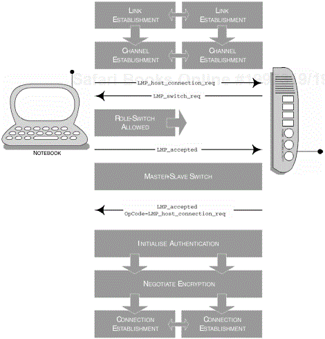
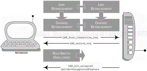
The master-slave switch operation is required [16] when the LAP is configured for multi-user [17] mode. The failure of a DT to perform this operation prohibits the successful connection to a LAP. Figure 10-18 provides an illustration of the events that occur when the DT fails to comply with the master-slave switch request. [18]
Table 10-29. The range of LMP PDUs available for encryption.
|
PDU |
PARAMETER |
|---|---|
|
|
Encryption Mode |
|
|
Key Size |
|
|
Random Number |
|
|
None |
Table 10-30 provides the HCI command and event combination that are used to perform the master-slave switch operation between the DT and LAP. This table represents one such method of performing a switch, where other HCI commands, such as the HCI_Create_Connection command, specify the same request as part of its parameter set up. In this instance, the Allow_Role_Switch parameter is used during the connection establishment to determine if a switch can be performed by the local device, that is, the device initiating the connection (DeviceA). The remote device (DeviceB) is duly notified with its corresponding HCI command, Accept_Connection_Request of whether it can be supported.
Table 10-31 provides the two LMP general response messages, which are mandatory for this profile. During an LMP_accepted operation, the response contains the OpCode of the operation that was successful; whereas the response from the LMP_not_ accepted provides the OpCode of the operation that was not successful. Accompanying this OpCode, a reason or error code is provided to help to determine why the operation failed; a full list of LMP reasons can be found in Appendix A.
The use of these general response messages is used in combination with the following LMP role-switch specific messages, which are provided in Table 10-32. What follows is a detailed exploration of the behaviour of both these devices when performing the master-slave switch operation. You may remember that the DT is capable of initiating a connection.
When DeviceB (or slave) initiates a master-slave switch, it terminates the final ACL packet and stops any further L2CAP transmissions. It then sends the LMP_slot_ offset command, which is immediately followed by the LMP_switch_req command. Similarly, if the master accepts the master-slave switch, it terminates all L2CAP transmissions and then issues a LMP_accepted if the transaction is a success. However, if the operation is rejected, then an LMP_not_accepted is provided as the response, with a specific reason for its failure. Furthermore, when the operation has been completed despite its success or failure, L2CAP communication is resumed.
Table 10-30. The command and two-stage event notification that are used in combination to perform the master-slave switch.
|
COMMAND |
PARAMETERS |
|---|---|
|
|
|
|
EVENT |
PARAMETERS |
|---|---|
|
|
|
|
|
|
Table 10-31. The general response messages used within LMP.
|
PDU |
PARAMETERS |
|---|---|
|
|
|
|
|
|
When DeviceA (or master) initiates a master-slave switch, it terminates the final ACL packet and stops any further L2CAP transmissions. It then sends an LMP_switch_ req. Similarly, if the slave accepts the master-slave switch, it terminates all L2CAP transmissions and then issues an LMP_slot_offset command, which is immediately followed by an LMP_accepted command. However, if the operation is rejected, then an LMP_not_accepted is provided as the response, with a specific reason for its failure. Furthermore, when the operation has been completed, despite its success or failure, L2CAP communication is resumed.
The LC layer is the lowest layer depicted in the dependencies of this profile; it is responsible for a large number of core capabilities. It manages air-to-interface transactions and determines the fundamental timing of ACL and SCO data packet transmission and reception, as well as coordinating the effort at its upper-edge with the LM. It also encompasses the management of the various packet types and the various inquiry and paging procedures available. The following subsections provide clarity with regard to the capabilities that are a requirement at the LC level for the LAN Access Profile. To further our understanding of the dependencies, we begin by examining in more detail the supported capabilities. If you are a developer providing profile-specific applications, then you may not wish to engage in a large part of this section, although in some audio-related applications direct access may be required, where a faster transport mechanism can be supported. Many manufacturers have nevertheless architected an audio-specific API for intelligible access to this component.
Table 10-33 summarises the broad capabilities that are expected from the LC. In the table, you will notice features are marked with M (Mandatory), O (Optional), X (Excluded), C (Conditional) and N/A (Not Applicable); these determine what is expected from the features at the LC.
Table 10-32. The PDUs available within LMP that are responsible for managing the role-switch behaviour.
|
PDU |
PARAMETERS |
|---|---|
|
|
|
|
|
|
Table 10-33. The summary of capabilities that are required for the LC to enable a compliant LAN Access Profile.
|
PROCEDURES |
DEVICEA |
DEVICEB |
|---|---|---|
|
Inquiry |
M |
X |
|
Inquiry Scan |
X |
M |
|
Paging |
M |
X |
|
Page Scan |
X |
M |
|
Inter-piconet |
M |
M |
|
Packet Types |
M |
M |
|
Voice Codecs |
X |
X |
An inquiry procedure is used to learn of the other devices in radio range, where the BD_ADDR and clock offsets are obtained; it is DeviceA that will enter an inquiry substate to perform this procedure. A device that wishes to be discovered (DeviceB) will enter an inquiry scan substate, where the device will respond with an inquiry response. In this state, DeviceB is waiting to receive an Inquiry Access Code (IAC). These modes of operation are discussed from a deeper application perspective in the Generic Access Profile, Chapter 2. It is here that specific rules are determined with regard to the behaviour of such devices and how long these devices can operate in such modes. When devices have been discovered, this information is passed over to the Service Discovery Application Profile, Chapter 3, which manages the specific attributes that make up that device. What we now understand is that the Bluetooth protocol stack must encompass and support such behavioural procedures for this profile to be considered compliant.
The inquiry substate and inquiry scan substate procedures are the initial methods used to learn of other devices in radio range; to this extent, the device has discovered sufficient information to gain a connection with the remote device. This is achieved when DeviceA has the intent to create a connection with DeviceB; DeviceA is placed into a paging substate, where it will periodically transmit the Device Access Code (DAC). The DAC is used to target the device directly and the clock offset is used to gain an idea of the clock cycle of DeviceB. These parameters were originally obtained during our inquiry procedures. If DeviceB wishes to be connected, then it will enter a page scan substate and will respond accordingly to DeviceA. An inquiry procedure may be avoided if the BD_ADDR is already known, although a connection may take a little longer if the clock offset is not known.
Inter-piconet capabilities describe the process that allows the master to manage multiple connections from slave devices. During a connection other users may temporarily witness degradation in the service that is being provided; however, the master must be capable of accepting new participants into the piconet.
There are numerous packet types available. Table 10-34 identifies those most commonly used for profile support. There are also a number of common packet types used for general-purpose transport; for example the ID packet is used for inquiry procedures and a POLL packet would be sent by DeviceA to determine if a slave is active on a channel.
The DM1 packet type is used to transmit control data over any connection, but may be used to transport a genuine payload. HV1, HV2 and HV3 are various SCO packet types to carry audio-specific data, where a DV packet can combine ACL and SCO specific data. Their support in this profile is reflected in Table 10-34. Various ACL packet types are also available; in fact, seven types including the DM1 type are attributed to carrying user-specific data. These include DH1, DM3, DH3, DM5, DH5 and AUX1. Similarly, Table 10-34 summarises their support in this profile.
The Management Entity (ME) component sits alongside the entire range of layers that make up the Bluetooth protocol stack and the PPP layer for this profile (see Figure 10-15). Its role is purely to coordinate the establishment of a connection and to respond and organise appropriate failures for inquiry and paging.
Table 10-34. The summary of packet types that are required for the LC to enable a compliant LAN Access Profile.
|
PACKET TYPE |
DT |
LAP |
|---|---|---|
|
|
M |
M |
|
|
M |
M |
|
|
M |
M |
|
|
M |
M |
|
|
M |
M |
|
|
M |
M |
|
|
X |
X |
|
|
X |
X |
|
|
X |
X |
|
|
X |
X |
When the DT has a problem in discovering or establishing a connection with a LAP, the link establishment fails and the user may reselect a new LAP in radio range that offers similar services.
The role of the ME extends to the supervision and the behaviour of the master-slave switch when the LAP is configured for the appropriate user-mode. Any reason for the failure of this operation will cause the baseband physical link to fail. Figure 10-19 provides an illustration of the sequence of events that may occur during a master-slave switch operation.
Figure 10-15 identifies all the components that make up the LAN Access Profile. This section now considers the components that are provided in the profile, but do not necessarily make up the Bluetooth protocol core.
The PPP is typically used for communication between two devices that use a serial interface; it is described in RFC1661. In the context of Bluetooth devices, PPP is used to transport packets over RFCOMM, which are subsequently passed over the network, packaged as IP data.
This layer refers to the operational aspects of PPP. It determines the capabilities that are specific to the levels of support and are now described in Sections 10.5.2.1.1, Initialisation and Shutting Down a PPP Connection to 10.5.2.1.4, HDLC Framing.
A device that is to behave as a LAP should register its capabilities in the CoD (as previously discussed in Section 10.5.1.1.1, Service Class). When the service is no longer required, the registration of its capabilities may be removed or disabled from the database and all active PPP connections terminated.
PPP requires an active RFCOMM session between the LAP and DT; if one does not exist, then the DT can create an RFCOMM session by using the RFCOMM channel as advertised in the LAP service record (see Section 10.5.1.2, Service Discovery).
The LAP and DT must then proceed to negotiate a PPP connection though the Link Control Protocol (LCP), which is incorporated within PPP. As part of the LCP negotiation process, an MTU will be negotiated as part of the connection; this, in turn, may become implementation-specific, depending on your product.
In Section 10.4.2.5, we discussed the reasons for the termination or disconnection of a service; in the majority of instances, the termination of each protocol layer is managed in an orderly fashion. During instances of a failed radio link, or if the DT device has stayed out of range for an extraordinary length of time, the dismantling of the layers is managed differently.
Each of the layers of the LAN Access Point are shown in Table 10-35, which explains how each should be appropriately managed during disconnection or termination.
The use of authentication during a PPP connection is not mandatory. PPP has several methods of authentication available to it and provides the administrator flexibility and additional security measures, along with the existing Bluetooth security, to secure his or her network.
As previously discussed, the user would be required to enter a username and password; failure to enter the correct information would result in a failed PPP connection. A range of authentication models are shown in Table 10-36.
The High-level Data Link Control (HDLC) is a means of organising or encapsulating data into frames over the network. It provides the ability to verify that data has been received correctly and is able to control the transmission rate of data. RFCOMM provides a means of HDLC framing and RFC1662 prescribes the HDLC requirements in PPP.
Table 10-35. The list of layers, which are made up during a PPP link with a LAP and DT.
|
LAYER |
PROCEDURE |
|---|---|
|
PPP |
Received termination notice and begins to inform its sub-layers. |
|
LCP |
The procedures for terminating this layer are defined in RFC1661. |
|
IPCP |
The producers for terminating this layer are defined in RFC1332, and will cease all IP communication. |
|
RFCOMM |
The disconnection of this layer is prescribed in Section 10.5.1.3, RFCOMM. |
|
L2CAP |
The disconnection of this layer is prescribed in Section 10.5.1.4, L2CAP. |
Table 10-36. The various authentication models available to PPP.
|
AUTHENTICATION |
REFERENCE |
|---|---|
|
PPP CHAP |
Challenge Handshake Authentication Protocol (CHAP), as prescribed in RFC1994. |
|
MS PPP CHAP Extensions |
The Microsoft PPP CHAP Extensions are detailed in RFC2433. |
|
PPP EAP |
The PPP Extensible Authentication Protocol (EAP) is defined in RFC2284. |
An IP interface becomes available when a PPP link has been established; more specifically, this is instantiated when the Internet Protocol Control Protocol (IPCP) link has been created and an IP address has been allocated. It is anticipated that a DT would have one active session with a LAP, although multiple sessions can exist when various LAPs provide multiple services. Here, the IP layer would be responsible for correctly routing IP data. It follows that the DT may require the establishment of such parameters as a default gateway and a Domain Name Server (DNS). These extensions can be found in RFC1877 and describe how the IPCP layer would negotiate DNS and NetBIOS Name Server (NBNS) addresses.
During a termination, the PPP link is stopped along with the IPCP layer, which also terminates the IP stack. Prior to termination, the IP stack is responsible for removing the IP address from its routing table.
Table 10-37. The various methods of allocating an IP address.
|
METHOD |
REFERENCE |
|---|---|
|
Fixed IP |
A permanent IP address assigned to the DT. Any duplicate IP addresses on the LAN would result in a termination of the duplicated connections. |
|
DHCP |
The DHCP provides greater flexibility in the assignment of IP addresses, where administrators can manage a corporation’s allocation of addresses. This reduces the risk of duplicate IP addresses being present on the LAN. |
|
Mobile-IP |
A specified IP configuration that provides DTs the flexibility to use multiple access points on the same LAN |
We discussed briefly that the DT would require an authentic IP address to operate correctly on the LAN. PPP dictates three methods on how this can be achieved; these are shown in Table 10-37.
The LAN Access Profile has many similarities to the Dial-up Networking Profile; both rely on the Generic Access Profile, the Serial Port Profile and a PPP implementation.
The LAN Access Profile omits the use of AT commands.
The existing usage models allow a DT to make use of the services provided by a LAP; these are the two roles that are defined by this profile.
A DT may utilize the services of many LAPs within radio range.
The LAP allows up to seven simultaneous connections from a DT; this provides the scenarios governed by the roles.
Future usage models will allow a DT to roam around an office whilst maintaining its connection to the LAN.
Bluetooth authentication and encryption is mandatory for this profile; failure to provide such support would result in a failed Bluetooth connection.
The DT is the initiator of the Bluetooth relationship.
The LAP requests to become master if it is configured for multi-user mode; no Bluetooth connection will occur if this switch fails.
The DT discovers available LAPs in radio range by performing an inquiry.
A LAP can be configured exclusively for a DT by configuring the LAP into single-user mode.
A device that wishes to behave as a LAP must register its purpose in the Service Discovery database.
A Service Discovery record is generated, detailing the parameters that apply to that specific service.
The DT incorporates a PPP Client and the LAP incorporates a PPP Server, both of which are implemented over RFCOMM.
PPP is used to enable an IP stack.
As part of the LCP negotiation, the MTU is also determined.
IPCP is responsible for allocating an IP address for the DT.
PPP Authentication is optionally available at this layer, requiring the user to enter a username and password; CHAP or EAP can be used.
[1] The current v1.1 specification restricts the mobility of a user. The user is fixed in one location and must be within radio range of where the access point resides. However, in the Bluetooth PAN Working Group, a hand-off technique is currently being architected to allow the mobility of users so that they can maintain that one initial connection.
[2] Specifically, the number of active connections permitted would be seven. This is due to the number of concurrent connections that can be maintained by one master device. The AM_ADDR represents the slave member address and is used to identify active participants; this is currently restricted to 3-bits, although slaves that become disconnected or parked give up this address.
[3] The double-click and right-click operations refer to a mouse that is connected to your DT device (in this example, a PC or notebook computer running a Microsoft Windows operating system) and where both operations trigger the same method of access. It is noted that an operation may vary from DT device to DT device; as such, the number of buttons may vary on a mouse and indeed no mouse may be connected. The example just draws your attention to how it may be possible and acknowledges that implementations may differ.
[5] SNMP is prescribed in RFC1157.
[6] A discussion on CHAP and EAP are provided in Section 10.5.2.1.3, Authentication Protocols.
[7] The LAN Access Profile outlines the use of IP, DHCP and DNS etc., stating that these components are optional.
[8] In Section 10.2.2, Future Usage Models, we stated that a hand-off between a DT and LAP is required for roaming and may require the LAP to initiate a connection with another LAP to pass on information about the handed-off DT.
[9] If no passkey is required, the default passkey is used, which is a single byte with all its bits set to zero.
[10] A reconnection would be subject to the available number of connections and the current QoS available.
[12] L2CAP payloads are passed directly onto LMP when implemented on a hostless system.
[15] Authentication here refers to the Bluetooth-specific authentication process.
[16] A LAP configured for multi-user mode must remain the master of the piconet.
[17] The DT may refuse the request to become the slave if it needs to remain the master.
[18] The Bluetooth protocol stack provides the flexibility of issuing a master-slave switch at any time during a Bluetooth connection establishment.


