We began our IoT platform-building journey with the end in mind. That is, we first conceived what our own IoT platform would be like and its high-level contents (refer to Figure 3-1 in Chapter 3). So far, we have established a fully functional cloud instance and the message broker.
Create a time-series database
Update Node-RED with additional nodes
Create a database listener
Build a REST API–based message publisher and retriever
Creating a Time-Series Core Database
We know that the time-series database is one of the critical blocks of our IoT platform. We established a general data storage schema for this in an earlier chapter. We will create the table now.
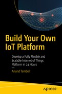
Create a new database for time-series storage

Create new user account for database access
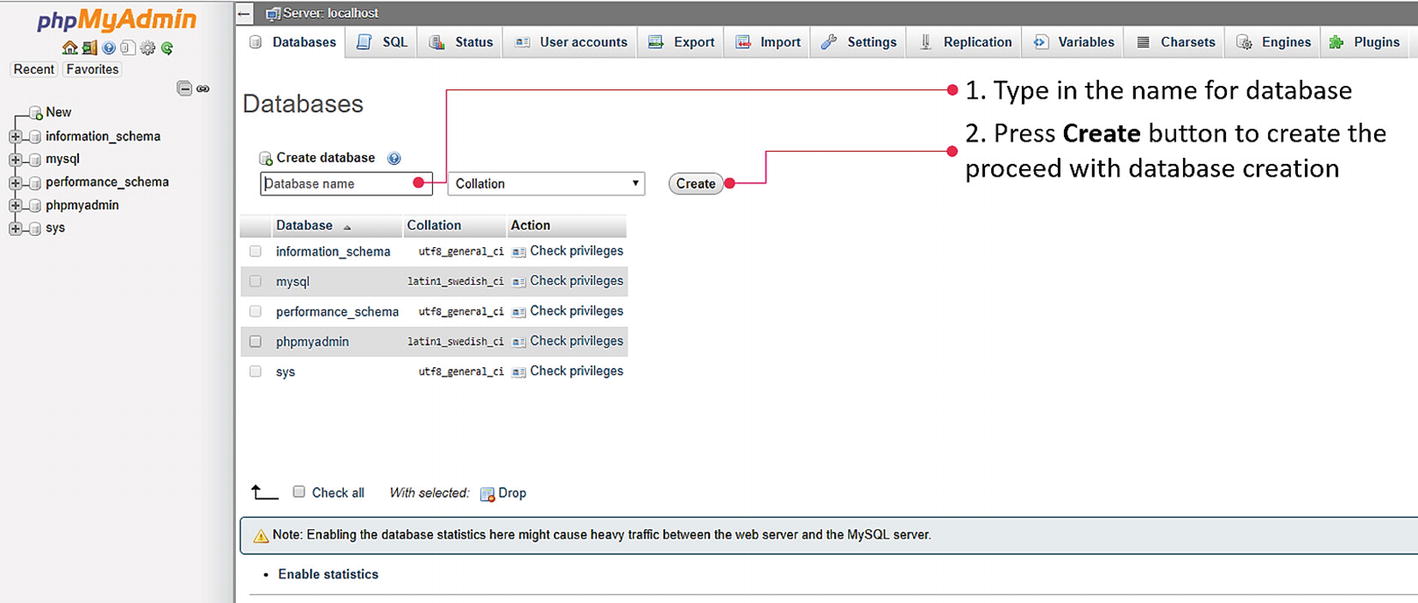
We now add a data table structure as per the schema mentioned earlier. To add a new table, select the New option under the database name in which this table is to be created (tSeriesDB in this case). Clicking the New option presents a dialog to input a new table name along with several columns.
We could add more or fewer columns at this stage. We can add or remove them later, so just provide an appropriate table name to proceed. We will use the table name thingData for our purpose.
Create data table with designated schema
We can mark this value as 0 (deleted = 0) when the data point is still valid or active, and mark it as deleted = 1 when we want it to be considered deleted. If we decide to completely remove this value from data storage, then we can delete this row as needed. This provision adds a layer of mistake-proofing for future applications, where it might mistakenly delete an entry. This option enables us to recover records; it can be considered a recycle bin of some kind in our time-series data storage block.

Updated data table schema for time-series data
Installing Required Nodes in Node-RED
With the required database and data structure ready in MySQL, it is time to enable Node-RED with the required additional nodes, and then configure it to couple with the database.
The default installation of Node-RED does not have a node to access MySQL. Therefore, we will add this node using Node-RED’s palette manager.

Adding MySQL node to the Node-RED palette
Having this node available means that now we can access our MySQL database from Node-RED. At this stage, the database and data table are ready to accept and store input values. The Node-RED functional instance is ready for configuration and programming, and the MQTT message broker is functional. This is enough setup to create a database listener and the related APIs.
Creating First Flow for Our Platform
Since the installation of Node-RED, we have not added anything to the node environment. Our canvas is therefore empty. We will create a very basic flow of this at the outset. Let’s use inject node for this purpose. The inject node allows us to inject messages into a flow. This could be a default string or a current timestamp. The message can be injected by clicking the button on the node, or we can set a recurring injection by setting a time interval in the node’s configuration.
Drag one inject node from the input palette area and place it in the workspace. Now drag a debug node to the workspace area, and then join the two nodes together by connecting an output of the inject node to the debug node. The debug node sends any input given to it on the debug message area on the sidebar on the right-hand side of the window.

Understanding Node-RED editor and first flow sequence
Note
For full details on how to use the Node-RED editor, keyboard shortcuts, and various terminologies, refer to the documentation at https://nodered.org/docs/user-guide/editor/ .
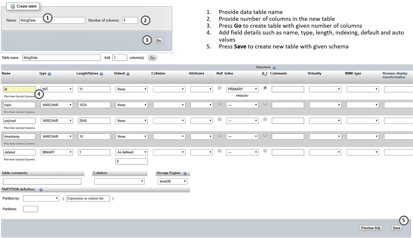
We will make two changes to our basic sequence. The inject node is currently sending a timestamp upon a button press; we will convert this into an autoinject action that repeats itself every 15 seconds. Then, we will add another node from the output palette, mqtt out, to our flow sequence and connect the output of a timestamp inject node to its input.
Adding MQTT Publish Capability
Configure timestamp and MQTT out nodes

First flow sequence and a timestamp utility for our platform
This flow sequence completes the M1 requirement (publish current timestamp) from the wish list in Chapter 4. Our first flow sequence is doing the same, where we are publishing the current timestamp into the message stream at a fixed interval of 15 seconds. Depending upon the requirements, you can modify this interval to suit your expectations; you can lower it to per second publish (which is too much, in my opinion) or you can raise it to one hour, which is reasonable in most cases.
REST API Message Publisher
Now that we have seen how to publish a message from Node-RED nodes to the MQTT message stream, we will build a REST API to enable the same. Part of our D4 requirement says that devices or applications should be able to publish a message using the HTTP protocol.
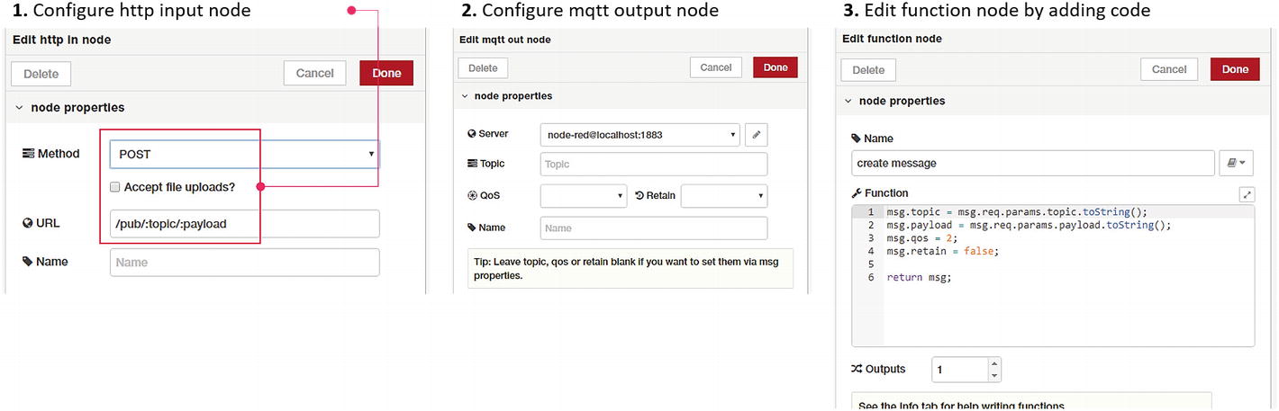
Configuration of API nodes and function code
Add another mqtt out node and adjust its settings as shown in Figure 7-9. Note that since we added a broker configuration while creating the timestamp utility, we can simply use the same configuration. We are not specifying the topic in the settings because we will be supplying it in the function node prior to publishing.

Complete flow sequence for message publish API
We are not doing any configuration or setting changes for the HTTP output node. Usually, the HTTP output node is only configured if additional headers are sent and configured or the HTTP response code needs to be changed. However, both the headers and the response code can be changed in the previous function node for the HTTP output.
In the create message function block, we receive input from the HTTP node. Two parameters, which are passed in the HTTP request, can be accessed in the msg message object. In the first two lines, we are assigning input parameters to topic and payload in the main message object. We are also setting the quality of service (QoS) to 2 for better reliability and to retain the flag at false, because we do not want each message to be retained.
As HTTP response node outputs (i.e., responds to the calling API with payload contents of the message object), we are modifying the payload with two keys. Setting up success = true indicates publishing success and payload with a meaningful response message.
This functionality cannot be tested in web browsers directly because we created a POST API. If you wish to use it in web browsers directly, simply convert it to GET by changing the HTTP input node settings. Alternatively, you can test this functionality using any other utility, such as the Postman interface.
We now have two functionalities added to our IoT platform: first, regular publishing of a current timestamp to the MQTT message stream; second, the REST API for publishing the message to the same MQTT message stream. Let’s augment this functionality further by adding the database listener.
Creating the Database Listener
A database listener is essentially an arrangement where a certain program or function listens to the live message stream and stores everything it listens to in the database. In our scenario, we have a live message stream established with MQTT. Now we will build a functionality where our program flow listens to the MQTT stream, and all the messages are logged into the time-series database.
To do this, we will add the mqtt input node to the workspace from the input palette. Then we add the debug node and connect it to the mqtt input node. This is the simplest flow sequence because we literally only have one thing to configure. Note that the MQTT broker details were already added.

Configure MQTT input node and deploy
We already have an active timestamp publisher, which is publishing the current timestamp every 15 seconds, and these messages should show up on the debug sidebar every 15 seconds.
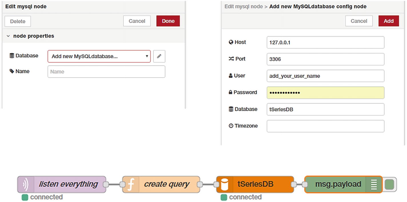
Add and configure MySQL node with our time-series database credentials
In the first three lines of the code, we are acquiring the latest timestamp from the date object and converting it to a zero-padded string for storage. The fourth code line is where we are writing our data INSERT query, and it follows standard MySQL insertion syntax.
The MySQL node in Node-RED requires the query to be passed in the msg object as msg.topic. The second-to-last line does that assignment, and then the function returns a modified object to the MySQL node. The MySQL node executes that query and adds the record in the database.
After deploying this flow, we can publish any message using cURL, or simply wait for 15 seconds so that the timestamp is published. Then log in to phpMyAdmin and verify in the database that the new record has been added.
With this flow active, from now on, any message published on the MQTT message stream is recorded in the database. Our database listener is now functional.
REST API Message Retriever
D1. Get a single data record. Enables applications and devices to query for a single data record from the time-series data storage based on a specified topic or topic pattern.
D2. Get several data records in a series. Enables applications and devices to query multiple data records based on a specified topic or topic pattern.

Retrieving messages from the time-series data storage
We have tied the outputs of two HTTP input nodes to the same flow sequence. By doing this, we are accommodating two variations of /get/:topic and /get/:topic/last/:count. The first one retrieves only one message from the time-series database, while with the second one specifies the number of the latest messages to be retrieved.
In this code, the first two lines check for the presence of a parameter count. Note that this parameter is required only when we want to request multiple latest messages. Therefore, in a single message query, this parameter is absent. And if it is absent, we set that parameter to the default value of 1.
Then, we are using a standard SELECT query to retrieve database records. In this query, we are using WHERE to search for the specified topic, and deleted=0 to select only the records that were not deleted. Additionally, we are using ORDER BY id DESC to retrieve the latest values and LIMIT the output by using the count parameter.
[{"id":8,"topic":"myTopic","payload":"myPayload","timestamp":"1543717154.899"}, {"id":7,"topic":"myTopic","payload":"myPayload","timestamp":"1543716966.189"}, {"id":6,"topic":"myTopic","payload":"myPayload","timestamp":"1543717132.192"}]
As these are GET API endpoints, you can test them directly in the browser too. If there are not enough data points (i.e., if you query for five data points under a topic while there are only three in storage, the API will respond to only the three that are available). It will be up to the downstream application to apply appropriate logic in handling such requests.
Verifying that Everything Is Working as Expected
We tested all four core services and utilities as we built them—the recurring current timestamp publisher, the database listener, the HTTP data posting service, and the HTTP data retrieval service.
At this stage, if we publish anything in the MQTT message stream, it will be published live at the same time that the database listener records it in the database. If any message is posted using the HTTP-post service, it will be visible live to MQTT-connected applications and devices (if they are subscribed to that topic). At the same time, this message is recorded in the database. You can retrieve one or more messages from the time-series data storage at any time, without relying on the live connection. All of this can be tested with the command line and a web browser.
Running Node-RED in the Background Continuously
One of the major concerns and an issue that we might encounter is, if the program crashes, we will have to log in to the cloud instance and restart it. That is cumbersome, however, it is more problematic to get to know this situation in first place. This is where, running a service in the background and resurrecting it whenever it fails, or crashes is important.
There are many options to achieve this. We will use one of the suitable options for our type of setup—a utility built using Node.js called forever.
The forever utility is a simple command-line tool, which is helpful in ensuring that a Node.js-based application runs continuously (i.e., forever). This means that if your application encounters an error and crashes, forever will take care of the issue and restart it for you.
In the preceding command, we are starting Node-RED with a log file as node-red.log, which means that all the output of the program on the console will go to this file, and we can examine this file as needed.

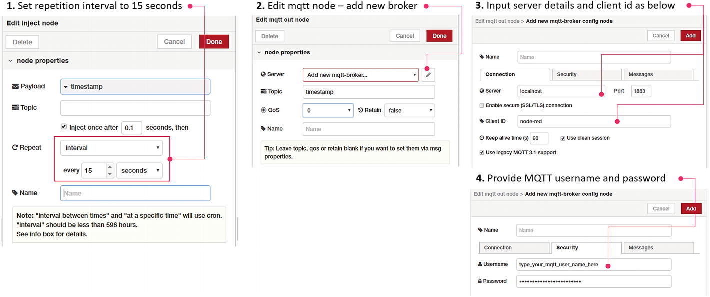
Critical services of our own IoT platform are now functional
Summary
From what we conceived in the initial chapters, we are about halfway through. We built a created time-series database and added the database listener to the platform. We also created two critical components for the platform in the REST API Interface block.
In the next chapter, we add WebSocket capabilities to our message broker and update access controls for enhanced security. We also see a few examples of how our IoT platform can interface with other applications and systems over MQTT socket connections for live data exchange.