
12 Mechanical Conveyors – Lifts, Escalators and Travelators

Roping Systems for Electric Lifts
Lift Machine Room and Equipment
Typical Single Lift Dimensions
Estimating the Number of Lifts Required
Vertical TRANsportation for the Disabled
To function efficiently and to provide access for the elderly and disabled, modern offices and public buildings are provided with suitably designed lift installations. Planning (as with all services) should commence early in the design programme. Priority must be given to locating lifts centrally within a building to minimise horizontal travel distance. Consideration must also be given to position, relative to entrances and stairs. Where the building size justifies several passenger lifts, they should be grouped together. In large buildings it is usual to provide a group of lifts near the main entrance and single lifts at the ends of the building. The lift lobby must be wide enough to allow pedestrian traffic to circulate and pass through the lift area without causing congestion. For tall buildings in excess of 15 storeys, high-speed express lifts may be used which bypass the lower floors.

Further Planning Considerations
Requirements:
Necessary in all buildings over three storeys high.
Essential in all buildings over a single storey if they are accessed by the elderly or disabled.
Minimum standard – one lift per four storeys.
Maximum walking distance to access a lift – 45m.
Floor space and lift car capacity can be estimated at 0·2m2 per person.
Lift speed:
Type |
Car speed (m/s) | |
|---|---|---|
Goods (electric or hydraulic) |
0·2–1 | |
Electric passenger |
<4 floors |
0·3–0·8 |
4–6 floors |
0·8–1·2 | |
6–9 floors |
1·2–1·5 | |
9–15 floors* |
1–5 | |
Paternoster |
<0·4 | |
Hydraulic passenger† |
0·1–1·0 | |
* Express lift that does not stop at the lower floor levels. The upper speed limit is 7m/s because of the inability of the human ear to adapt to rapidly changing atmospheric conditions.
† Overall theoretical maximum travel distance is 21m vertically, therefore limited to four or five storeys.
Electric motor – low-speed lifts operate quite comfortably with an AC motor to drive the traction sheave through a worm gear (see page 570). For faster speed applications a DC motor is preferable. This is supplied via a mains generator for each lift motor. DC motors have historically provided better variable voltage controls, more rapid and smoother acceleration, quieter operation, better floor levelling and greater durability in resisting variable demands. Recent developments with AC motors have made them more acceptable and these are now becoming more widely used.
Refs. BS 5655: Lifts and service lifts (several parts).
BS EN 81: Safety rules for the construction and installation of lifts (several parts).
BS 8486: Examination and test of new lifts before putting into service (Part 1, Electric, and Part 2, Hydraulic).
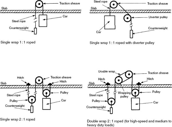
Roping Systems for Electric Lifts
High-tensile steel ropes are used to suspend lift cars. They have a design factor of safety of 10 and are usually at least four in number. Ropes travel over grooved driving or traction sheaves and pulleys. A counterweight balances the load on the electric motor and traction gear.
Methods for roping vary:
Single wrap 1:1 – the most economical and efficient of roping systems but is limited in use to small-capacity cars.
Single wrap 1:1 with diverter pulley – required for larger capacity cars. It diverts the counterweight away from the car. To prevent rope slip, the sheave and pulley may be double wrapped.
Single wrap 2:1 – an alternative for use with larger cars. This system doubles the load-carrying capacity of the machinery but requires more rope and also reduces the car speed by 50%.
Double wrap – used to improve traction between the counterweight, driving sheave and steel ropes.
Single wrap 3:1 – used for heavy goods lifts where it is necessary to reduce the force acting upon the machinery bearings and counterweight. The load-carrying capacity is increased by up to three times that of uniform ratio, but the capital costs are higher with increased pulleys and greater length of rope. By comparison, the car speed is also reduced to one-third.
Drum drive – a system with one set of ropes wound clockwise around the drum and another set anticlockwise. It is equally balanced, as one set unwinds the other winds. The disadvantage of the drum drive is that as height increases the drum becomes less controllable, limiting its application to rises of about 30m.
Compensating rope and pulley – used in tall buildings where the weight of the ropes in suspension will cause an imbalance on the driving gear and also a possible bouncing effect on the car. The compensating ropes attach to the underside of the car and counterweight to pass around a large compensating pulley at low level.

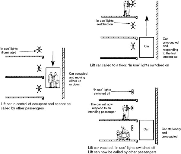
The single automatic push button system is the simplest and least sophisticated of controls. The lift car can be called and used by only one person or group of people at a time. When the lift car is called to a floor, the signal lights engraved ‘in use’ are illuminated on every floor. The car will not respond to any subsequent landing calls, nor will these calls be recorded and stored. The car is under complete control of the occupants until they reach the required floor and have departed the lift. The ‘in use’ indicator is now switched off and the car is available to respond to the next landing call. Although the control system is simple and inexpensive by comparison with other systems, it has its limitations for user convenience. It is most suited to light traffic conditions in low-rise buildings such as nursing homes, small hospitals and flats.
Ref. BS 5655-7: Lifts and service lifts. Specification for manual control devices, indicators and additional fittings.
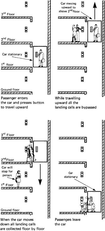
Down collective – stores calls made by passengers in the car and those made from the landings. As the car descends, landing calls are answered in floor sequence to optimise car movement. If the car is moving upwards, the lift responds to calls made inside the car in floor sequence. After satisfying the highest registered call, the car automatically descends to answer all the landing calls in floor sequence. Ony one call button is provided at landings. This system is most suited to flats and small hotels, where the traffic is mainly between the entrance lobby and specific floors.
Full or directional collective – a variation in which car and landing calls are immediately stored in any number. Upward and downward intermediate landing calls are registered from one of two directional buttons. The uppermost and lowest floors only require one button. The lift responds to calls in floor order independent of call sequence, first in one direction and then in the other. It has greater flexibility than the down collective system and is appropriate for offices and departmental stores where there is more movement between intermediate floors.
Two cars may be coordinated by a central processor to optimise efficiency of the lifts. Each car operates individually on a full or down collective control system. When the cars are at rest, one is stationed at the main entrance lobby and the other, which has call priority, at a mid-point within the building or at another convenient floor level. The priority car will answer landing calls from any floor except the entrance lobby. If the priority car is unable to answer all call demands within a specific time, the other car if available will respond. A similar system may also apply to three cars, with two stationary at the entrance lobby and one available at mid-point or the top floor.
With the supervisory control system, each car operates on full collective control and will respond to calls within a dedicated zone. A micro-processor determines traffic demand and locates cars accordingly to each operating zone.

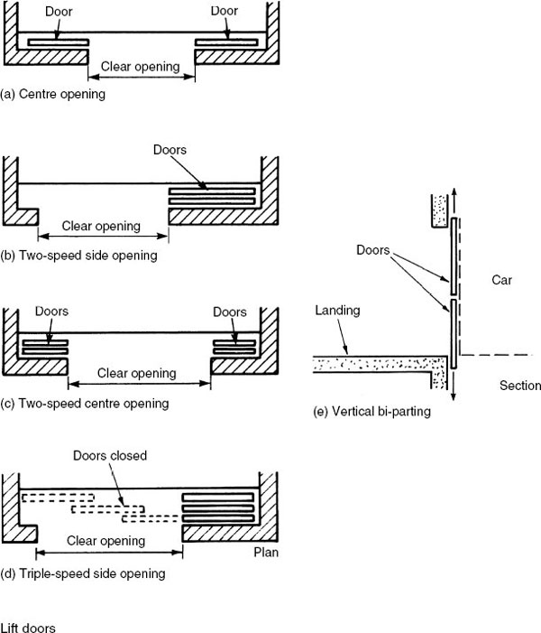
Door operation is by an electric motor through a speed reduction unit, clutch drive and connecting mechanism. The types of entrance and doors form a vital part of the lift installation. The average lift car will spend more time at a floor during passenger transfer time than it will during travel. For general passenger service, either side opening, two-speed or even triple-speed side-opening doors are preferred. The most efficient in terms of passenger handling is the two-speed centre opening. The clear opening may be greater and usable clear space becomes more rapidly available to the passengers. Vertical centre-bi-parting doors are suitable for very wide openings, typical of industrial applications.
Lift Machine Room and Equipment
Wherever possible the machine room should be sited above the lift shaft. This location minimises the length of ropes and optimises efficiency. The room should be ventilated, but the vent opening must not be over the equipment. Machinery must be well secured to a concrete base. To reduce sound transmission and vibration, compressed cork, dense rubber or a composite layer is used as an intermediate mounting.
A steel lifting beam is built into the structure above the machinery for positioning or removing equipment for maintenance and repair. Sufficient floor space is necessary for the inspection and repair of equipment. Recommended machine room dimensions are given in BS 5655-6: Lifts and service lifts. Code of practice for the selection, installation and location of new lifts.
To prevent condensation the room must be well insulated and heated to provide a design air temperature between 10°C and 40°C. Walls, ceiling and floor should be smooth finished and painted to reduce dust formation. A regular pattern of room cleaning and machinery maintenance should be scheduled.
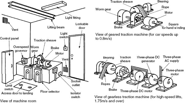
Buffers – located at the base of the shaft. They are usually oil loaded for lift speeds >1·5m/s and otherwise spring loaded. Some variations use compressible plastics.
Overspeed governor – a steel rope passes round a tension pulley in the pit and a governor pulley in the machine room. It also attaches to the lift car’s emergency braking system. Overspeeding locks the governor as it responds to spring-loaded flyweight inertia from the centrifugal force in its accelerating pulley. This also switches off power to the lift. The tightening governor rope actuates the safety braking gear.
Safety gear – hardened steel wedges are arranged in pairs each side of the lift car to slow down and stop the car by frictional contact with the car guide rail. Slow- and medium-speed lifts have pairs of hardened steel cams which instantaneously contact a steel channel secured to the lift wall.

Details of an Electric Lift Installation
To satisfy the need for economies in lift-manufacturing processes, dimensions are limited. For this purpose, guidance in BS 5655-6 refers to the internationally agreed standards, BS ISO 4190-1 and 2. Therefore, architects will have to establish passenger transport requirements as a preliminary design priority. The size of lift shaft will depend upon the car capacity and the space required for the counterweight, guides and landing door. The shaft extends below the lowest level served to provide a pit. This permits a margin for car overtravel and a location for car and counterweight buffers. The pit must be watertight and have drainage facilities. Shaft and pit must be plumb and the internal surfaces finished smooth and painted to minimize dust collection. A smoke vent with an unobstructed area of 0·1m2 is located at the top of the shaft. The shaft is of fire-resistant construction as defined for ‘protected shafts’ in the Building Regulations. This will be at least 30 minutes and is determined by building function and size. No pipes, ventilating ducts or cables (other than those specifically for the lift) must be fitted within the shaft. A clearance is required at the top of the lift for car overtravel. Counterweight location is at the back or side of the car.

Refs. BS 5655-6: Lifts and service lifts. Code of practice for selection, installation and location of new lifts.
BS EN 81: Safety rules for the construction and installation of lifts.
BS ISO 4190-1 and 2: Lift (Elevator) installation.
Building Regulations, Approved Document B3: Internal fire spread (structure).
Typical Single Lift Dimensions
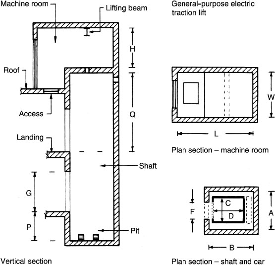
All dimensions in metres:

Note: Dimension E refers to the car door height.
A paternoster consists of a series of open-fronted two-person cars suspended from hoisting chains. Chains run over sprocket wheels at the top and bottom of the lift shaft. The lift is continuously moving and provides for both upward and downward transportation of people in one shaft. Passengers enter or leave the car while it is moving, therefore waiting time is minimal. Passengers will have to be fairly agile, which limits this type of installation to factories, offices, universities, etc. It is not suitable in buildings that accommodate the infirm or elderly! When a car reaches its limit of travel in one direction, it moves across to the adjacent set of hoisting chains to engage with car guides and travel in the other direction. In the interests of safety, car speed must not exceed 0·4m/s.

Paternosters convey about 600 persons per hour. This type of lift has the advantage of allowing passengers to begin their journeys undelayed, regardless of travel direction. Simplicity of control gear adds to the advantages, resulting in fewer breakdowns by eliminating normal processes of stopping, starting, accelerating and decelerating. They are most suited to medium-rise buildings.
Oil-hydraulic Lifting Arrangements
Direct acting – the simplest and most effective method, but it requires a borehole below the pit to accommodate the hydraulic ram. The ram may be one piece or telescopic. In the absence of a counterweight, the shaft width is minimised. This will save considerably on construction costs and leave more space for general use.
Side acting – the ram is connected to the side of the car. For large-capacity cars and heavy goods lifts, two rams may be required, one each side of the car. A borehole is not necessary, but due to the cantilever design and eccentric loading of a single ram arrangement, there are limitations on car size and load capacity.
Direct side acting – the car is cantilevered and suspended by a steel rope. As with side acting, limitations of cantilever designs restrict car size and payload. Car speed may be increased.
Indirect side acting – the car is centrally suspended by steel rope and the hydraulic system is inverted.

Details of Oil-hydraulic Lift Installation
Originally, hydraulic lifts used mains water supply as the operating medium. The main was pressurised from a central pumping station to service lift installations in several buildings. The oil-hydraulic system has oil pressure fed by a pump into a cylinder to raise the ram and lift the car. Each lift has its own pumping unit and controller. These units are usually sited at or near to the lowest level served, no more than 10 m from the shaft. The lift is ideal in lower rise buildings where moderate speed and smooth acceleration is preferred.
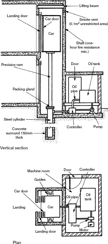
Car speed ranges from 01 to 1m/s and the maximum travel is limited to about 21 m. The lift is particularly suitable for goods lifts and for hospitals and old people’s homes. Most hydraulic lifts carry the load directly to the ground, therefore as the shaft does not bear the loads, construction is less expensive than for a comparable electric lift installation.
Refs. BS 5655-10.2.1: Lifts and service lifts. Specification for the testing and examination of lifts and service lifts. Hydraulic lifts. Commissioning tests for new lifts.
BS 8486-2: |
Examination and test of new lifts before putting into service. Specification for means of determining compliance with BS EN 81. Hydraulic lifts. |
BS EN 81-2: |
Safely rules for the construction and installation of lifts. Hydraulic lifts. |
Oil-hydraulic Lift Pumping Unit and Packing Gland
Upward movement – the oil pressure must be gradually increased. The up solenoid valve is energised by an electric current and opens to allow oil to enter above piston D. As the area of piston D is greater than valve C, the oil pressure closes the valve and allows high-pressure oil to flow to the cylinder and lift the ram and the car. Downward movement – the oil pressure must be gradually decreased. The lowering solenoid valve is energised by an electric current and opens, allowing oil to flow back to the tank through the bypass. As the area of piston A is greater than valve B, the reduced oil pressure behind the piston allows valve B to open. Oil flows into the tank and the car moves downward.
A special packing gland with several seals is required between the cylinder and ram.

Lift performance depends on:
acceleration;
retardation;
car speed;
speed of door operation; and
stability of speed and performance with variations of car load.
The assessment of population density may be found by allowing between one person per 9·5m2 of floor area to 11·25m2 of floor area. For unified starting and finishing times 17% of the population per five minutes may be used. For staggered starting and finishing times 12% of the population may be used.
The number of lifts will have an effect on the quality of service. Four 18-person lifts provide the same capacity as three 24-person lifts but the waiting time will be about twice as long with the three-car group.
The quality of service may be found from the interval of the group: 25–35 seconds interval is excellent, 35–45 seconds is acceptable for offices, 60 seconds for hotels and 90 seconds for flats.
Further criteria for the comfort and convenience of lift users:
Directional indication of location of the lift lobby for people unfamiliar with the building.
Call buttons at landings and in the car positioned for ease of use with unambiguous definition for up and down directions.
Call buttons to be at a level appropriate for use by people with disabilities and small children.
Call display/car location display at landings to be favourably positioned for a group of people to watch the position of all cars and for them to move efficiently to the first car arriving.
Call lights and indicators with an audible facility to show which car is first available and in which direction it is travelling.
Lobby space of sufficient area to avoid congestion by lift users and general pedestrian traffic in the vicinity.
Estimating the Number of Lifts Required
Example: An office block with 20 storeys above ground floor having unified starting and stopping times is to have a floor area above the ground floor of 8000m2 and floor pitch of 3m. A group of four lifts, each car having a capacity of 20 persons and a car speed of 2·5m/s, are specified. The clear door width is to be 1·1m and the doors are to open at a speed of 0·4m/s. Estimate the interval and quality of service that is to be provided.
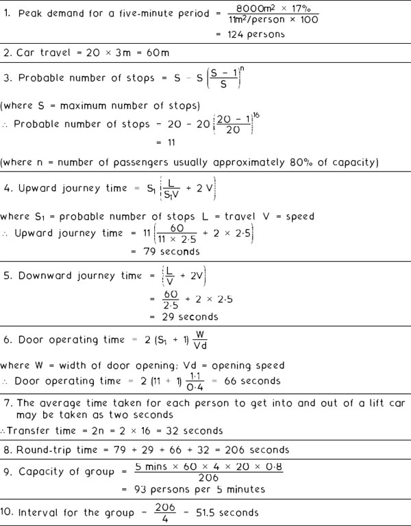
The capacity of the group of lifts and the interval for the group are satisfactory. (Note: Cars less than 12 capacity are not satisfactory.)
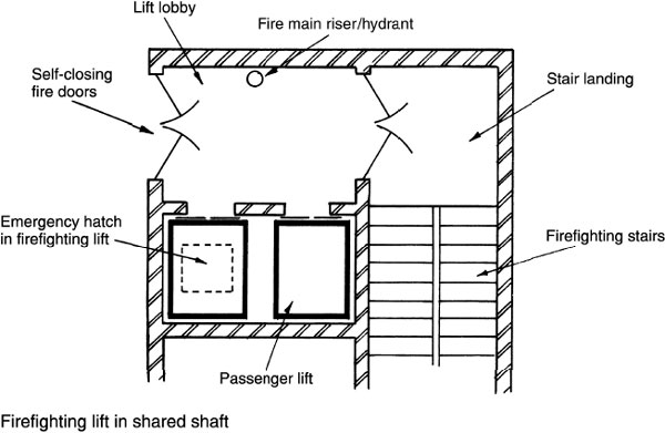
During the early part of the twentieth century, it became apparent that the growing number of high-rise buildings would require special provisions for fire control. The firefighting lift was conceived as a means of rapidly accessing the upper floors. Early innovations prioritised the passenger lift by means of a ‘break-glass’ key switch which brought the lift to the ground floor immediately. This is now unlikely to be acceptable to building insurers and the fire authorities. It is also contrary to current building standards which specify a separate lift installation specifically for firefighting purposes.
Special provisions for firefighting lifts:
Minimum duty load of 630kg.
Minimum internal dimensions of 1·1m wide × l·4m deep × 2·0m high.
Provision of an emergency escape hatch in the car roof.
Top-floor access time – maximum 60 seconds.
Manufactured from non-combustible material.
A two-way intercommunications system installed.
Door dimensions at least 0 8m wide × 2·0m high of fire-resisting construction.
Two power supplies – mains and emergency generator.

Building Regulations – structures with floors at a height greater than 18m above fire service vehicle access (usually ground level), or with a basement greater than 10m below fire service vehicle access, should have accessibility from a purpose-made firefighting lift. All intermediate floors should be served by the lift. Firefighting lifts for other situations are optional as defined in Approved Document B5, Section 18, but will probably be required by the building insurer.
Minimum number of firefighting shafts containing lifts:

Note: Qualifying floor areas, as defined for fire service vehicle access.
Maximum distance of firefighting lift shaft to any part of a floor is 60m. Hydrant outlets should be located in the firefighting lobby.
Refs. Building Regulations, Approved Document B: Fire safety, Volume 2, Part B5, Section 17: Access to buildings for firefighting personnel.
BS 9999: Code of practice for fire safety in the design, management and use of buildings.
Vertical Transportation for the Disabled
A passenger lift is the most suitable means for conveying wheelchair occupants between floor levels. However, a platform lift (see next page) or a platform stair lift may be used if access is only between two levels. Platform lifts must not be used where they would obstruct a designated means of fire escape on a stairway.
Lift provisions:
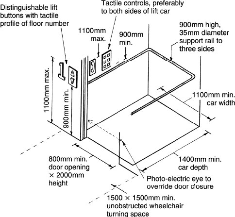
Landing space in front of lift doors should be sufficient to allow a wheelchair to turn and reverse into a lift car.
Control/call panel should be prominent and easily distinguishable from its background.
Time delay on door opening to be sufficient to allow wheelchair access. Doors fitted with a reactivation device to prevent people and/or wheelchair from being trapped in closing doors.
Control panel in lift car positioned on a side wall, at least 400mm from a corner at a height accessible while seated.
Control panel floor numbers to be raised on buttons to assist the visually impaired.
Audible announcement of the floor levels served to help people with visual difficulties.
Visual display of floor levels served to assist people with hearing impairments.
Emergency telephones to be provided with inductive couplers for the benefit of hearing aid users. Location at an accessible height from a wheelchair.
Alarm controls provided at an accessible height with a visual display to confirm the bell has responded for the benefit of lift users with hearing difficulties.
Vertical Transportation for the Disabled – Platform Lift
Passenger lifts can accommodate wheelchairs. Purpose-designed platform lifts can also be provided for wheelchair users in domestic and public buildings.
Power – Electricity, three phase 400V motor and 230V single phase for controls. For domestic use, hydraulic power with 230V single phase control is more common. Lift speed – 0.15m/s maximum.
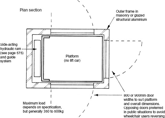
Typical dimensions (mm) –
Platform depth |
Platform width |
Application |
1250 |
900 |
Domestic |
1400 |
1100 |
Public |
Controls – can be automatic, but usually maintained command, otherwise known as push or hold to run, i.e. continuous hand pressure.
Refs. Disability Discrimination Act.
European Machinery Directive, 2006/42/EC (2nd Edition 2010).
Building Regulations Approved Document M: Access to and use of buildings.
BS 6440: Powered vertical lifting platforms having non-enclosed or partially enclosed liftways intended for use by persons with impaired mobility. Specification.
BS 8300: Design of buildings and their approaches to meet the needs of disabled people. Code of practice.
Supplementary Work in Connection with Lift Installation
Builder’s work – machine room:
Door and window openings sealed against the weather.
Lockable and safe access for lift engineers and building facilities manager.
Provide and secure a trapdoor to raise and lower machinery.
Secure all non-structural floors, decking and temporary scaffolding in position.
Temporary guards and ladders to be secured in position.
Dimensions to the requirements of BS 5655 or lift manufacturer’s specification.
Provide reinforced concrete floor and plinths to include at least nine rope holes.
Treat floor to prevent dust.
Provide lifting beam(s) and pad stone support in adjacent walls.
Heating and ventilation to ensure a controlled temperature between 4°C and 40°C.
Electrical work:
Reduced voltage temporary lighting and power supplies for portable tools during construction.
Main switch fuse for each lift at the supply company’s intake.
Run power mains from intake to the motor room and terminate with isolating switches.
Lighting and 13 amp power supply in the machine room.
Independent light supply from the intake to the lift car with control switchgear in the machine room or halfway down the well.
Lighting to the pit with a switch control in the lowest floor entrance.
Permanent lighting in the well to consist of one lamp situated 500mm maximum from the highest and lowest points with intermediate lamps at 7m maximum spacing.
Calculations with regard to the architect’s plans and structural loadings.
Form a plumb lift well and pit according to the architect’s drawings and to tolerances acceptable to the lift manufacturer (known as Nominal Minimum Plumb – the basic figures in which the lift equipment can be accommodated).
Minimum thickness of enclosing walls – 230mm brickwork or 130mm reinforced concrete.
Applying waterproofing or tanking to the pit and well as required.
Paint surfaces to provide a dust-free finish.
Provide dividing beams for multiple wells and inter-well pit screens. In a common well, a rigid screen extending at least 2.5m above the lowest landing served and a full depth of the well between adjacent lifts.
Secure lift manufacturer’s car guides to lift well walls.
Make door opening surrounds as specified and secure one above the other.
Build or cast in inserts to secure lift manufacturer’s door sills.
Perform all necessary cutting away and making good for landing call buttons, door and gate locks, etc.
Provide smoke vents of at least 0.1m2 free area per lift at the top of the shaft.
Apply finishing coat of paintwork to all exposed steelwork.
Provide temporary guards for openings in the well.
Supply and install temporary scaffolding and ladders to lift manufacturer’s requirements.
Offload and store materials, accessories, tools and clothing in a secure, dry and illuminated place protected from damage and theft.
Provide mess rooms, sanitary accommodation and other welfare facilities in accordance with the Construction (Health, Safety and Welfare) Regulations. Note: These Regulations are now integrated with the CDM Regs. (see page 6).
Provide access, trucking and cranage for equipment deliveries.
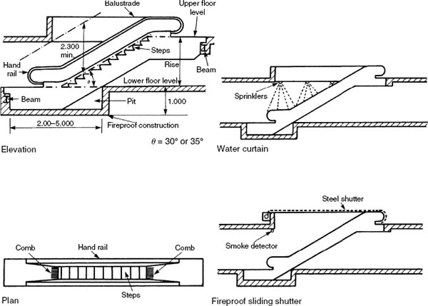
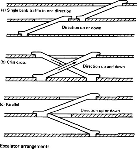
Escalators are moving stairs used to convey people between floor levels. They are usually arranged in pairs for opposing directional travel to transport up to 12000 persons per hour between them.
The maximum carrying capacity depends on the step width and conveyor speed. Standard steps widths are 600, 800 and 1000mm, with speeds of 0.5 and 0.65m/s. Control gear is less complex than that required for lifts as the motor runs continuously with less load variations. In high-rise buildings space for an escalator is unjustified, since the full height and the high speed of modern lifts provides for a better service.
To prevent the exposed openings from facilitating fire spread, a water sprinkler installation (see Part 13) can be used to automatically produce a curtain of water over the well. An alternative is a fireproof shutter actuated from a smoke detector or fusible links.
Refs. BS 5656-1: Safety rules for the construction and installation of escalators and passenger conveyors. Specification and proformas for test and examination of new installations.
BS 5656-2: Escalators and moving walks.
BS EN 115: Safety of escalators and moving walks. Construction and installation.
Escalator Arrangements and Capacity
Escalator configurations vary depending on the required level of service. The one-directional single bank avoids interruption of traffic, but occupies more floor space than other arrangements.
A criss-cross or cross-over arrangement is used for moving traffic in both directions.
Escalator capacity formula to estimate the number of persons (N) moved per hour:
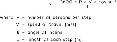
E.g. an escalator inclined at 35°, operating with one person per 400mm step at 0·65m/s.
![]()
Travelators – also known as autowalks, passenger conveyors and moving pavements. They provide horizontal conveyance for people, prams, luggage trolleys, wheelchairs and small vehicles for distances up to about 300 metres. Slight inclines of up to 12° are also possible, with some as great as 18°, but these steeper pitches are not recommended for use with wheeled transport.
Applications range from retail, commercial and store environments to exhibition centres, railway and airport terminals. Speeds range between 0·6 and 1·3m/s; any faster would prove difficult for entry and exit. When added to walking pace, the overall speed is about 2·5m/s.
There have been a number of experiments with different materials for the conveyor surface. These have ranged from elastics, rubbers, composites, interlaced steel plates and trellised steel. The latter two have been the most successful in deviating from a straight line, but research continues, particularly into possibilities for variable speed lanes of up to 5m/s. However, there could be a danger if bunching were to occur at the exit point.

Ref. BS 5656-2: Escalators and moving walks.
BS EN 115: Safety of escalators and moving walks. Construction and installation.
Stair lifts have been used in hospitals, homes for the elderly and convalescent homes for some time. In more recent years, manufacturers have recognised the domestic need and have produced simple applications which run on a standard steel joist bracketed to the adjacent wall. Development of Part M to the Building Regulations, ‘Access to and use of buildings’, provides that staircases in all future dwellings are designed with the facility to accommodate and support a stair lift or a wheelchair lift. This will allow people to enjoy the home of their choice, without being forced to seek alternative accommodation.
Standard 230 volt single-phase AC domestic electrical supply is adequate to power a stair lift at a speed of about 0.15m/s. A 24 volt DC transformed low-voltage supply is used for push button controls. Features include overspeed brake, safety belt, optional swivel seat, folding seat and arm rests, and a manual lowering device. The angle of support rail inclination is usually within the range of 22°–50° within a maximum travel distance of about 20m.

Ref. BS EN 81-40: Safety rules for the construction and installation of lifts. Special lifts for the transport of persons and goods. Stairlifts and inclined lifting platforms intended for persons with impaired mobility.