
8 Arithmetical Macros
Numerical data imply the ability to do arithmetical operations, and almost all PLCs provide some arithmetical operations, such as add, subtract, multiply, and divide. Arithmetical functions will retrieve one or more values, perform an operation, and store the result in memory. As an example, Figure 8.1 shows an ADD function that will retrieve and add two values from sources labeled source A and source B and will store the result in destination C. The list of arithmetical functions (macros) described for the PIC16F648A-based PLC is as follows The increment and decrement functions are unary, so there is only one source
ADD (source value 1, source value 2, destination): Add two source values and put the result in the destination
SUB (source value 1, source value 2, destination): Subtract the second source value from the first one and put the result in the destination.
INC (source value, destination): Increment the source and put the result in the destination
DEC (source value, destination): Decrement the source and put the result in the destination
In this chapter, the following six arithmetical macros are described for the PIC16F648A-based PLC:
R1addR2RaddKR1subR2RsubKincRdecR
The file definitions. inc, included within the CD-ROM attached to this book, contains all arithmetical macros defined for the PIC16F648A-based PLC. Let us now consider these macros in detail

FIGURE 8.1
The ADD function.
TABLE 8.1
Algorithm and Symbol of the Macro R1addR2
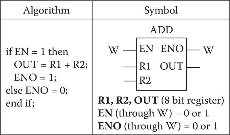
8.1 Macro R1addR2
The algorithm and the symbol of the macro R1addR2 are depicted in Table 8.1. Figure 8.2 shows the macro R1addR2 and its flowchart. In this macro, EN is a Boolean input variable taken into the macro through W, and ENO is a Boolean output variable sent out from the macro through W. Output ENO

FIGURE 8.2
(a) The macro R1addR2 and (b) its flowchart.
TABLE 8.2
Algorithm and Symbol of the Macro RaddK

follows the input EN. This means that when EN = 0, ENO is forced to be 0, and when EN = 1, ENO is forced to be 1. This is especially useful if we want to carry out more than one operation based on a single input condition. R1 and R2 refer to 8-bit source variables from where the source values are taken into the macro, while OUT refers to an 8-bit destination variable to which the result of the macro is stored. When EN = 1, the macro R1addR2 adds the contents of two 8-bit variables R1 and R2 and stores the result into the 8-bit output variable OUT (OUT = R1 + R2).
8.2 Macro RaddK
The algorithm and the symbol of the macro RaddK are depicted in Table 8.2. Figure 8.3 shows the macro RaddK and its flowchart. In this macro, EN is a Boolean input variable taken into the macro through W, and ENO is a Boolean output variable sent out from the macro through W Output ENO follows the input EN This means that when EN = 0, ENO is forced to be 0, and when EN = 1, ENO is forced to be 1. R and K are source values. R refers to an 8-bit source variable, while K represents an 8-bit constant value. OUT refers to an 8-bit destination variable to which the result of the macro is stored When EN = 1, the macro RaddK adds the content of the 8-bit variable R and the 8-bit constant value K and stores the result into the 8-bit output variable OUT (OUT = R + K)
8.3 Macro R1subR2
The algorithm and the symbol of the macro R1subR2 are depicted in Table 8.3. Figure 8.4 shows the macro R1subR2 and its flowchart. In this macro, EN is a Boolean input variable taken into the macro through W,

FIGURE 8.3
(a) The macro RaddK and (b) its flowchart.
and ENO is a Boolean output variable sent out from the macro through W. Output ENO follows the input EN. This means that when EN = 0, ENO is forced to be 0, and when EN = 1, ENO is forced to be 1. R1 and R2 refer to 8-bit source variables from where the source values are taken into the macro, while OUT refers to an 8-bit destination variable to which the result of the macro is stored. When EN = 1, the macro R1subR2 subtracts the content of the 8-bit variable R2 from the content of the 8-bit variable R1 and stores the result into the 8-bit output variable OUT (OUT = R1 - R2).
TABLE 8.3
Algorithm and Symbol of the Macro R1subR2
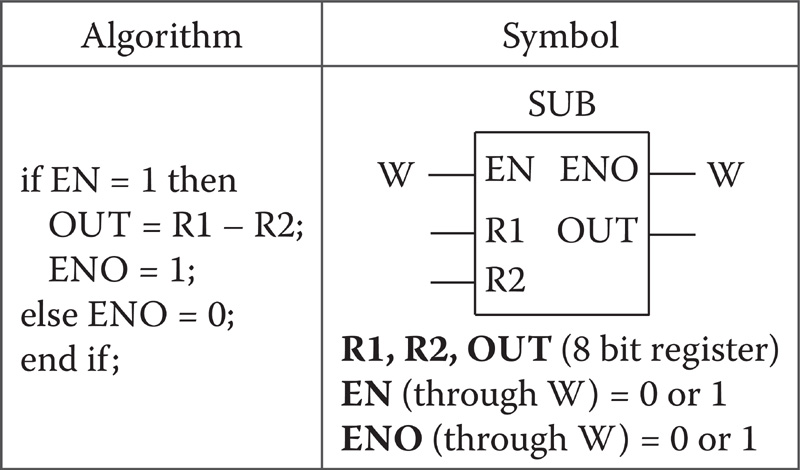
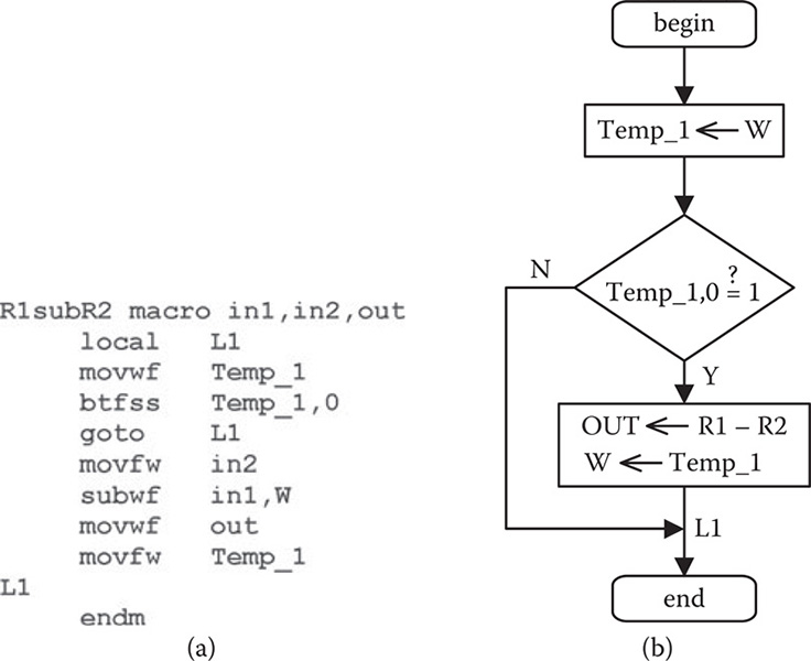
FIGURE 8.4
(a) The macro R1subR2 and (b) its flowchart.
8.4 Macro RsubK
The algorithm and the symbol of the macro RsubK are depicted in Table 8.4. Figure 8.5 shows the macro RsubK and its flowchart. In this macro, EN is a Boolean input variable taken into the macro through W, and ENO is a Boolean output variable sent out from the macro through W. Output ENO follows the input EN. This means that when EN = 0, ENO is forced to be 0, and when EN = 1, ENO is forced to be 1. R and K are source values. R refers to an 8-bit source variable, while K represents an 8-bit constant value.
TABLE 8.4
Algorithm and Symbol of the Macro RsubK
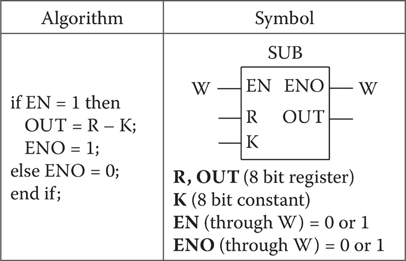

FIGURE 8.5
(a) The macro RsubK and (b) its flowchart.
OUT refers to an 8-bit destination variable to which the result of the macro is stored. When EN = 1, the macro RsubK subtracts the 8-bit constant value K from the content of the 8-bit variable R and stores the result into the 8-bit output variable OUT (OUT = R - K).
8.5 Macro incR
The algorithm and the symbol of the macro incR are depicted in Table 8.5. Figure 8.6 shows the macro incR and its flowchart. In this macro, EN is a Boolean input variable taken into the macro through W, and ENO is a Boolean output variable sent out from the macro through W. Output ENO
TABLE 8.5
Algorithm and Symbol of the Macro incR
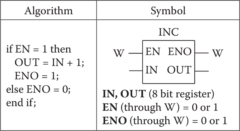
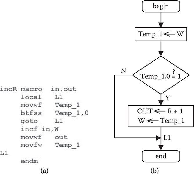
FIGURE 8.6
(a) The macro incR and (b) its flowchart.
follows the input EN This means that when EN = 0, ENO is forced to be 0, and when EN = 1, ENO is forced to be 1. IN refers to an 8-bit source variable from where the source value is taken into the macro, while OUT refers to an 8-bit destination variable to which the result of the macro is stored When EN = 1, the macro incR increments the content of the 8-bit variable IN and stores the result into the 8-bit output variable OUT (OUT = IN + 1).
8.6 Macro decR
The algorithm and the symbol of the macro decR are depicted in Table 8.6. Figure 8.7 shows the macro decR and its flowchart. In this macro, EN is a Boolean input variable taken into the macro through W, and ENO is a
TABLE 8.6
Algorithm and Symbol of the Macro decR

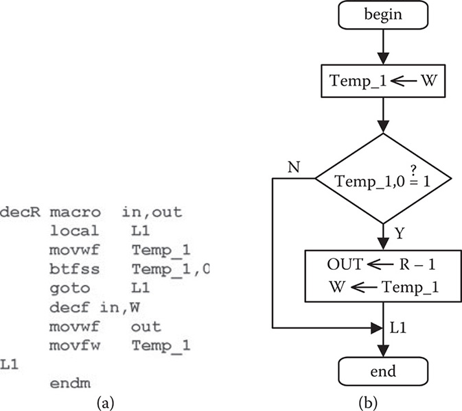
FIGURE 8.7
(a) The macro decR and (b) its flowchart.
Boolean output variable sent out from the macro through W. Output ENO follows the input EN. This means that when EN = 0, ENO is forced to be 0, and when EN = 1, ENO is forced to be 1. IN refers to an 8-bit source variable from where the source value is taken into the macro, while OUT refers to an 8-bit destination variable to which the result of the macro is stored When EN = 1, the macro decR decrements the content of the 8-bit variable IN and stores the result into the 8-bit output variable OUT (OUT = IN - 1).
8.7 Examples for Arithmetical Macros
In this section, we will consider two examples, UZAM_plc_16i16o_ex14. asm and UZAM_plc_16i16o_ex15. asm, to show the usage of arithmetical macros In order to test one of these examples, please take the related file UZAM_plc_16i16o_ex14. asm or UZAM_plc_16i16o_ex15. asm from the CD-ROM attached to this book, and then open the program by MPLAB IDE and compile it. After that, by using the PIC programmer software, take the compiled file UZAM_plc_16i16o_ex14. hex or UZAM_plc_16i16o_ ex15 hex, and by your PIC programmer hardware, send it to the program memory of PIC16F648A microcontroller within the PIC16F648A-based PLC. To do this, switch the 4PDT in PROG position and the power switch in OFF position. After loading the file UZAM_plc_16i16o_ex14. hex or UZAM_ plc_16i16o_ex15 hex, switch the 4PDT in RUN and the power switch in ON
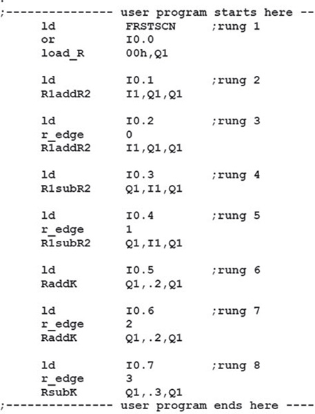
FIGURE 8.8
The user program of UZAM_plc_16i16o_ex14.asm.
position. Please check the program's accuracy by cross-referencing it with the related macros.
Let us now consider these example programs: The first example program UZAM_plc_16i16o_ex14. asm is shown in Figure 8.8. It shows the usage of the following arithmetical macros: R1addR2, RaddK, R1subR2, and RsubK. The ladder diagram of the user program of UZAM_plc_16i16o_ex14. asm, shown in Figure 8.8, is depicted in Figure 8.9.
In the first rung, Q1 is cleared, i.e., 8-bit constant value 00h is loaded into Q1, by using the macro load_R. This process is carried out once at the first program scan by using the FRSTSCN NO contact. Another condition to carry out the same process is the NO contact of the input I0.0. This means that when this program is run, during the normal PLC operation, if we force the input I0.0 to be true, then the above-mentioned process will take place
In rungs 2 and 3, we see how the arithmetical macro R1addR2 could be used. In rung 2, the addition process Q1 = I1 + Q1 is carried out, when I0.1 goes true. With this rung, if I0.1 goes and stays true, the content of I1 will be
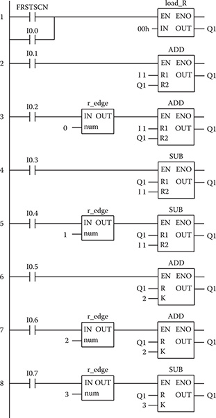
FIGURE 8.9
The ladder diagram of the user program of UZAM_plc_16il6o_exl4.asm.
added to the content of Q1 on every PLC scan. Rung 3 provides a little bit different usage of the arithmetical macro R1addR2. Here, we use a rising edge detector macro in order to detect the state change of input I0.2 from OFF to ON. So this time, the addition process Q1 = I1 + Q1 is carried out only at the rising edges of I0.2.
In rungs 4 and 5, we see how the arithmetical macro R1subR2 could be used. In rung 4, the subtraction process Q1 = Q1 - I1 is carried out when I0.3 goes true. With this rung, if I0.3 goes and stays true, the content of I1 will be subtracted from the content of Q1, on every PLC scan In rung 5, a rising edge detector macro is used in order to detect the state change of input I0.4 from OFF to ON So this time, the subtraction process Q1 = Q1 - I1 is carried out only at the rising edges of I0.4.
In rungs 6 and 7, we see how the arithmetical macro RaddK could be used. In rung 6, the addition process Q1 = Q1 + 2 is carried out, when I0.5 goes true With this rung, if I0.5 goes and stays true, the constant value 2 will be added to the content of Q1 on every PLC scan In rung 7, a rising edge detector macro is used in order to detect the state change of input I0.6 from OFF to ON So this time, the addition process Q1 = Q1 + 2 is carried out only at the rising edges of I0.6.
In the last rung, the subtraction process Q1 = Q1 - 3 is carried out at the rising edges of I0.7.
The second example program, UZAM_plc_16i16o_ex15. asm, is shown in Figure 8.10. It shows the usage of the following arithmetical macros: incR and
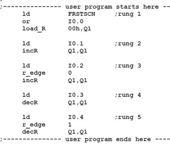
FIGURE 8.10
The user program of UZAM_plc_16i16o_ex15.asm.
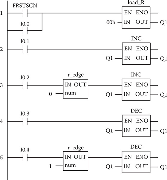
FIGURE 8.11
The ladder diagram of the user program of UZAM_plc_16i16o_ex15.asm.
decR. The ladder diagram of the user program of UZAM_plc_16i16o_ex15. asm, shown in Figure 8.10, is depicted in Figure 8.11.
In the first rung, Q1 is cleared, i.e., 8-bit constant value 00h is loaded into Q1, by using the macro load_R. This process is carried out once at the first program scan by using the FRSTSCN NO contact. Another condition to carry out the same process is the NO contact of the input I0.0. This means that when this program is run, during the normal PLC operation, if we force the input I0.0 to be true, then the above-mentioned process will take place.
In rung 2, when I0.1 goes and stays true, Q1 is incremented on every PLC scan.
In rung 3, Q1 is incremented at each rising edge of I0.2.
In rung 4, when I0.3 goes and stays true, Q1 is decremented on every PLC scan.
In rung 5, Q1 is decremented at each rising edge of I0.4.