
15 Application Example
This chapter describes an example remotely controlled model gate system and makes use of the PIC16F648A-based PLC to control it for different control scenarios
15.1 Remotely Controlled Model Gate System
Figure 15.1 shows the remotely controlled model gate system, used in this chapter as an example to show how the PIC16F648A-based PLC can be utilized in the control of real systems. In this system, when the DC motor turns backward (respectively forward) the gate is opened (respectively closed). To control the DC motor in backward and forward directions, PLC outputs Q0.0 and Q0.1 are used, respectively. In the system, there are two buttons, B0 and B1, and they both have only one normally open (NO) contact. When pressed, the button B0 (respectively, B1) is used to give the control system the following order: "open the gate" (respectively, "close the gate"). PLC inputs I0.0 and I0.1 are used for identifying the ON or OFF states of the buttons B0 and B1, respectively When the gate is completely open, it applies the F1 force, shown in Figure 15.1, to the limit switch 1 (LS1). In this case, the NO contact of LS1 is closed. To detect whether or not the gate is completely open, the input I0.2 is utilized. When the gate is completely closed, it applies the F2 force, shown in Figure 15.1, to the limit switch 2 (LS2). In this case, the NO contact of LS2 is closed To detect whether or not the gate is completely closed, the PLC input I0.3 is utilized. An infrared (IR) transmitter/receiver sensor is used to detect if there is any obstacle in the gate's path. This is very important because when the gate is closing, there should not be any obstacle in its path in order not to cause any damage to anybody or anything When the light emitted from the IR transmitter is received from the IR receiver, the NO contact of the sensor is closed In this case, we conclude that there is no obstacle in the path When the light emitted from the IR transmitter is not received from the IR receiver, the NO contact of the sensor is open, i e , in its normal condition This means that there is an obstacle in the path To detect whether or not there is an obstacle in the path, the PLC input I0.4 is utilized In addition, there is also a radio frequency (RF) transmitter/receiver used as a remote control mechanism within the system In the RF transmitter, there
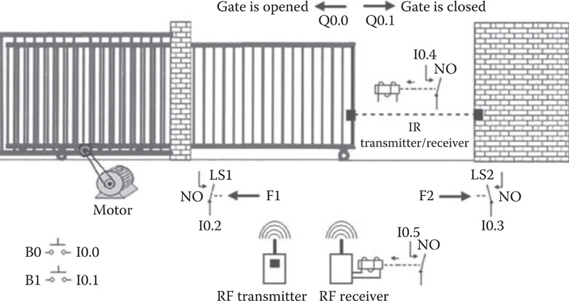
FIGURE 15.1
The remotely controlled model gate system.
is a button. When this button is pressed, the RF waves are emitted from the transmitter, and they are received from the RF receiver. In this case, NO contact at the RF receiver is closed, signaling the button press from the RF transmitter counterpart. To detect whether or not the RF transmitter button is pressed, the PLC input 10.5 is utilized.
The DC motor control circuit embedded within the model gate system is depicted in Figure 15.2, where there are two relays, Relay 1 and Relay 2,
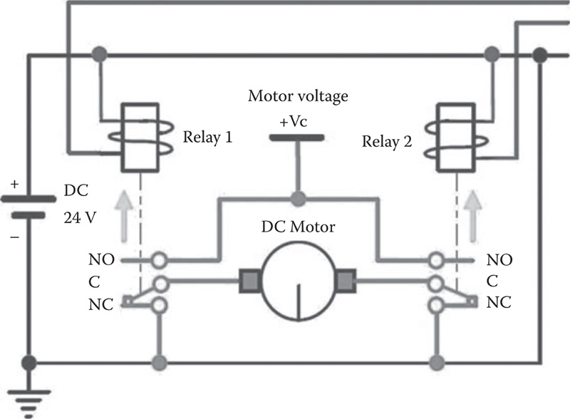
FIGURE 15.2
The DC motor control circuit embedded within the model gate system.
Table 15.1 State of the DC Motor Based on the Two Relays
Relay 1 |
Relay 2 |
DC Motor |
OFF (Q0.1 = 0) |
OFF (Q0.0 = 0) |
OFF (not working) |
OFF (Q0.1 = 0) |
ON (Q0.0 = 1) |
Turns backward (the gate is opened) |
ON (Q0.1 = 1) |
OFF (Q0.0 = 0) |
Turns forward (the gate is closed) |
ON (Q0.1 = 1) |
ON (Q0.0 = 1) |
OFF (not working) |
operating on 24 V DC. These relays both have a single-pole double-throw (SPDT) contact, with the terminals named normally open (NO), common (C), and normally closed (NC) As can be seen, terminal C is shared between the other two contacts The normal states of the contacts are shown in Figure 15.2. In this case, the C and NC terminals of both relays are closed, while C and NO terminals are open If any of these relays' coils are energized, then the contacts are actuated, and thus the C and NC terminals of the relay are open, while C and NO terminals are closed With this setup, by means of the two relays we can have the DC motor turning forward or backward, as shown in Table 15.1. It is important to note that if both relays are ON, then the DC motor will not be working One terminal of each relay coil is connected to 24 V DC, while the other one is left unconnected To operate any relay it is necessary to connect its open terminal to the ground of the 24 V DC The control of the DC motor is achieved by means of the Q0.0 and Q0.1 outputs of the PLC. As can be seen from Figure 15.2, when Q0.0 is ON (and Q0.1 is OFF), the NO contact of Q0.0 will switch on Relay 2, in which case the motor turns backward and the gate is opened Similarly, when Q0.1 is ON (and Q0.0 is OFF), the NO contact of Q0.1 will switch on Relay 1, in which case the motor turns forward and the gate is closed. Figure 15.3 shows the wiring of the PIC16F648A-based PLC with the remotely controlled model gate system In this setup, when any of the NO contact of the model gate system is closed or a button is pressed, 5 V DC is applied to related PLC input
15.2 Control Scenarios for the Model Gate System
In this section we will declare eight different control scenarios for the remotely controlled model gate system as follows:
When B0 is being pressed, the gate shall open.
Once B0 is pressed, the gate shall open.
Once B0 is pressed, the gate shall open. The motor shall stop when the gate is completely open

FIGURE 15.3
Wiring of the PIC16F648A-based PLC with the model gate system.Once B0 is pressed, the gate shall open. The motor shall stop when the gate is completely open. Once B1 is pressed, the gate shall close. The motor shall stop when the gate is completely closed.
If the gate is not closing, then once B0 is pressed, the gate shall open. The motor shall stop when the gate is completely open. If the gate is not opening, then once B1 is pressed, the gate shall close The motor shall stop when the gate is completely closed
If the gate is not closing, then once B0 or the RF transmitter button is pressed, the gate shall open The motor shall stop when the gate is completely open. When the gate is completely open, it shall wait 5 s before automatically closing The motor shall stop when the gate is completely closed.
If the gate is not closing, then once B0 or the RF transmitter button is pressed, the gate shall open The motor shall stop when the gate is completely open When the gate is completely open, it shall wait 5 s before automatically closing The motor shall stop when the gate is completely closed When the gate is closing, if there is an obstacle in the gate's path, the gate shall open. In this case it shall wait 5 s before automatically closing as defined above.
Combine the previous seven control scenarios in a single program. By using three inputs, I1.2, I1.1, and I1.0, only one of the scenarios will be selected and will work at any time.
15.3 Solutions for the Control Scenarios
In this section, we will consider the solutions to the above-declared eight control scenarios for the remotely controlled model gate system, namely, UZAM_ plc_16i16o_exX.asm (X = 34, 35, 36, 37, 38, 39, 40, 41). In order to test one of these examples, please take the related file UZAM_plc_16i16o_exX asm (X = 34, 35, 36, 37, 38, 39, 40, 41) from the CD-ROM attached to this book, and then open the program by MPLAB IDE and compile it. After that, by using the PIC programmer software, take the compiled file UZAM_plc_16i16o_exX hex (X = 34, 35, 36, 37, 38, 39, 40, 41), and by your PIC programmer hardware send it to the program memory of PIC16F648A microcontroller within the PIC16F648A-based PLC. To do this, switch the 4PDT in PROG position and the power switch in OFF position. After loading the file UZAM_plc_16i16o_ exXhex (X = 34, 35, 36, 37, 38, 39, 40, 41), switch the 4PDT in RUN and the power switch in ON position. Finally, you are ready to test the respective example program Let us now consider the example programs in the following sections
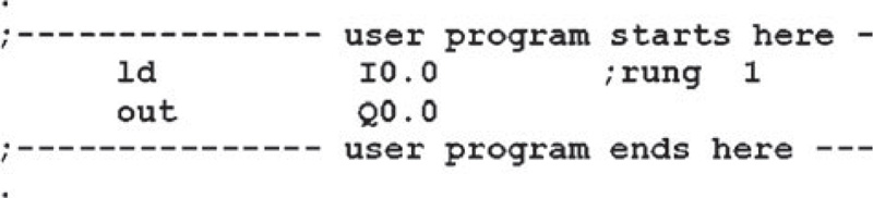
FIGURE 15.4
The user program of UZAM_plc_16i16o_ex34.asm.
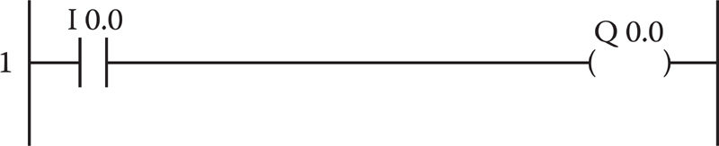
FIGURE 15.5
The ladder diagram of the user program of UZAM_plc_16il6o_ex34.asm.
15.3.1 Solution for the First Scenario
The user program of UZAM_plc_16il6o_ex34.asm, shown in Figure 15.4, is provided as a solution for the first scenario. The ladder diagram of the user program of UZAM_plc_16il6o_ex34.asm is depicted in Figure 15.5. In this example, when BO (10.0) is being pressed, the gate will open (QO.O will be ON). However, in this case, if BO is released, then the gate will stop. This means that the program does not remember whether or not BO was pressed.
15.3.2 Solution for the Second Scenario
The user program of UZAM_plc_16il6o_ex35.asm, shown in Figure 15.6, is provided as a solution for the second scenario. The ladder diagram of the user program of UZAM_plc_16il6o_ex35.asm is depicted in Figure 15.7. In this example, once BO (10.0) is pressed, with the help of NO contact QO.O connected parallel to NO contact 10.0, the gate will open (QO.O will be ON). Here,

FIGURE 15.6
The user program of UZAM_plc_16il6o_ex35.asm.
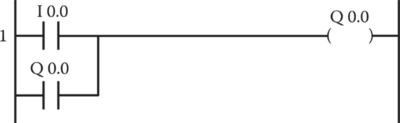
FIGURE 15.7
The ladder diagram of the user program of UZAM_plc_16i16o_ex35.asm.
the NO contact Q0.0 is a "sealing contact," and helps the program to remember whether B0 was pressed. The problem is that when the gate is completely opened, the motor will not stop.
15.3.3 Solution for the Third Scenario
The user program of UZAM_plc_16i16o_ex36.asm, shown in Figure 15.8, is provided as a solution for the third scenario. The ladder diagram of the user program of UZAM_plc_16i16o_ex36.asm is depicted in Figure 15.9. In this example, once B0 (I0.0) is pressed, with the help of NO contact Q0.0 connected parallel to NO contact I0.0, the gate will open (Q0.0 will be ON). Here, when the gate is opened completely, the motor will stop with the help of the NC contact of I0.2 inserted before the output Q0.0.

FIGURE 15.8
The user program of UZAM_plc_16i16o_ex36.asm.
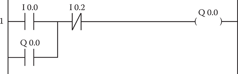
FIGURE 15.9
The ladder diagram of the user program of UZAM_plc_16i16o_ex36.asm.

FIGURE 15.10
The user program of UZAM_plc_16i16o_ex37.asm.
15.3.4 Solution for the Fourth Scenario
The user program of UZAM_plc_16i16o_ex37.asm, shown in Figure 15.10, is provided as a solution for the fourth scenario. The ladder diagram of the user program of UZAM_plc_16i16o_ex37.asm is depicted in Figure 15.11. In this example, once B0 (I0.0) is pressed, with the help of NO contact Q0.0 connected parallel to NO contact I0.0, the gate will open (Q0.0 will be ON). Here, when the gate is opened completely, the motor will stop with the help of the NC contact of I0.2 inserted before the output Q0.0. Similarly, once B1 (I0.1) is pressed, with the help of the NO contact of Q0.1 connected parallel to NO contact I0.1, the gate will close (Q0.1 will be ON) Here, when the gate is closed completely, the motor will stop with the help of the NC contact of I0.3 inserted before the output Q0.1. The problem with this example is that if both B0 and B1 are pressed at the same time, then both outputs will be ON This is not a desired situation The solution to this problem is given in the next example
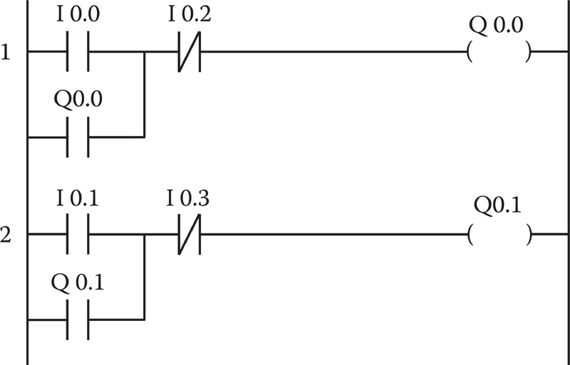
FIGURE 15.11
The ladder diagram of the user program of UZAM_plc_16i16o_ex37.asm.
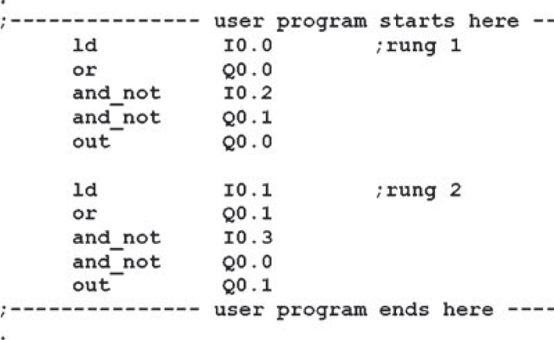
FIGURE 15.12
The user program of UZAM_plc_16i16o_ex38.asm.
15.3.5 Solution for the Fifth Scenario
The user program of UZAM_plc_16i16o_ex38.asm, shown in Figure 15.12, is provided as a solution for the fifth scenario. The ladder diagram of the user program of UZAM_plc_16i16o_ex38.asm is depicted in Figure 15.13. In this example, if the gate is not closing (Q0.1 = 0), once B0 (I0.0) is pressed, then the gate will open (Q0.0 will be ON) with the help of the NO contact of Q0.0 connected parallel to NO contact I0.0. In this case, when the gate is opened completely (I0.2 = 1, and therefore the NC contact of I0.2 will open), the motor will stop with the help of the NC contact of I0.2 inserted before the output Q0.0. Similarly, if the gate is not opening (Q0.0 = 0), once B1 (I0.1) is pressed, then the gate will close (Q0.1 will be ON) with the help of NO contact Q0.1 connected parallel to the NO contact of I0.1. Here, when the gate is closed completely (I0.3 = 1, and therefore the NC contact of I0.3 will open), the motor
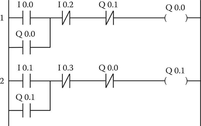
FIGURE 15.13
The ladder diagram of the user program of UZAM_plc_16i16o_ex38.asm.
will stop with the help of the NC contact of 10.3 inserted before the output Q0.1. Therefore, once the gate is being opened, we cannot force it to close, and vice versa.
15.3.6 Solution for the Sixth Scenario
The user program of UZAM_plc_16ii6o_ex39.asm, shown in Figure 15.14, is provided as a solution for the sixth scenario. The ladder diagram of the user program of UZAM_plc_16i16o_ex39.asm is depicted in Figure 15.15. In this example, if the gate is not closing (Q0.1 = 0), once B0 (I0.0) or the RF transmitter button (I0.5) is pressed, then the gate will open (Q0.0 will be ON) with the help of the NO contact of Q0.0 connected parallel to the NO contact of I0.0. In this case, when the gate is opened completely (I0.2 = 1, and therefore the NC contact of I0.2 will open), the motor will stop with the help of the NC contact of I0.2 inserted before the output Q0.0. When the gate is completely open (I0.2 = 1), an on-delay timer (TON_8) is used to obtain a (100 x 52.4288 ms) 5.24 s time delay. After waiting 5.24 s, the status bit TON8_Q0 of the on-delay timer becomes true If the gate is not opening (Q0.0 = 0), and if the NO contact of TON_8Q0 is closed (i e , 5 24 s time delay has elapsed), then the gate will close (Q0.1 will be ON) with the help of the NO contact of Q0.1 connected parallel to the NO contact of TON8_Q0. Here, when the gate is
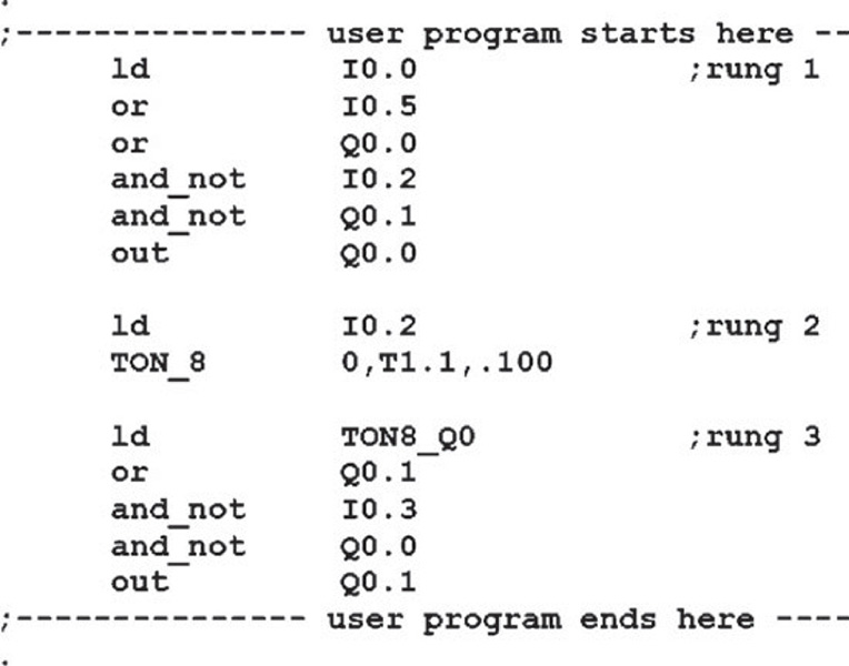
FIGURE 15.14
The user program of UZAM_plc_16i16o_ex39.asm.
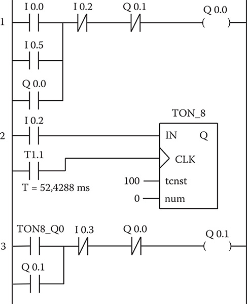
FIGURE 15.15
The ladder diagram of the user program of UZAM_plc_16i16o_ex39.asm.
closed completely (I0.3 = 1, and therefore the NC contact of I0.3 will open), the motor will stop with the help of the NC contact of I0.3 inserted before the output Q0.1.
15.3.7 Solution for the Seventh Scenario
The user program of UZAM_plc_16i16o_ex40.asm, shown in Figure 15.16, is provided as a solution for the seventh scenario. The ladder diagram of the user program of UZAM_plc_16i16o_ex40.asm is depicted in Figure 15.17. In this example, if the gate is not closing (Q0.1 = 0), once B0 (I0.0) or the RF transmitter button (I0.5) is pressed, then the gate will open (Q0.0 will be ON) with the help of NO contact Q0.0 connected parallel to NO contact I0.0. In this case, when the gate is opened completely (I0.2 = 1, and therefore the NC contact of I0.2 will open), the motor will stop with the help of the NC contact of I0.2 inserted before the output Q0.0. If the gate is closing (Q0.1 = 1) and the presence of an obstacle is detected in the gate's path (I0.4 = 0), then the gate will open (Q0.0 will be ON). When the gate is completely open (I0.2 = 1), an on-delay timer (TON_8) is used to obtain a
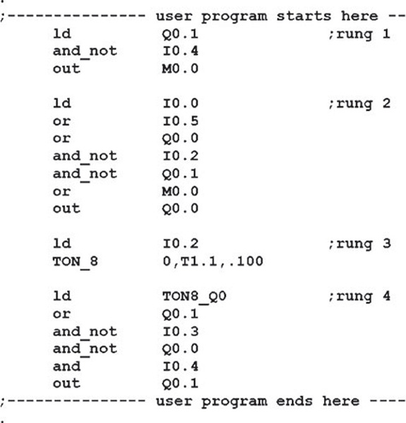
FIGURE 15.16
The user program of UZAM_plc_16il6o_ex40.asm.
(10 x 52.4288 ms) 5.24 s time delay. After waiting 5.24 s, the status bit TON8_ Q0 of the on-delay timer becomes true. If the gate is not opening (QO.O = 0), and if the NO contact of TON8_Q0 is closed (i.e., the 5.24 s time delay has elapsed), then the gate will close (Q0.1 will be ON) with the help of NO contact Q0.1 connected parallel to the NO contact of TON8_Q0. Here, when the gate is closed completely (10.3 = 1, and therefore the NC contact of 10.3 will open), the motor will stop with the help of the NC contact of 10.3 inserted before the output Q0.1. If the gate is closing (Q0.1 = 1) and the presence of an obstacle is detected in the gate's path (10.4 = 0), then the output Q0.1 will be switched OFF by means of the NO contact of 10.4 inserted before the output Q0.1.
15.3.8 Solution for the Eighth Scenario
In this last solution, the previous seven solutions are all combined in a single program. In order to choose one of the previous solutions, three inputs, 11.2, 11.1, and 11.0, are used. Table 15.2 shows the selected scenarios based on the logic signals applied to these three inputs.

FIGURE 15.17
The ladder diagram of the user program of UZAM_plc_16i16o_ex40.asm.
TABLE 15.2
Scenarios Chosen Based on the Input Signals
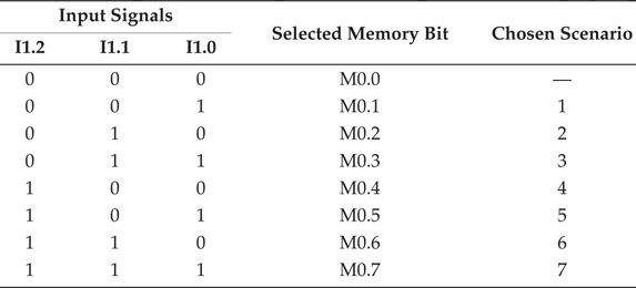
The user program of UZAM_plc_16i16o_ex41.asm, shown in Figure 15.18, is provided as a solution for the eighth scenario. The ladder diagram of the user program of UZAM_plc_16i16o_ex41.asm is depicted in Figure 15.19. In the first rung, a 3 x 8 decoder is implemented, whose inputs are I1.2, I1.1, and I1.0, and whose outputs are markers M0.0, M0.1, M0.2, M0.3, M0.4, M0.5, M0.6, and M0.7. The Boolean signals applied to the inputs
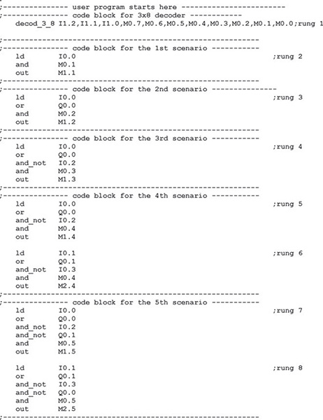
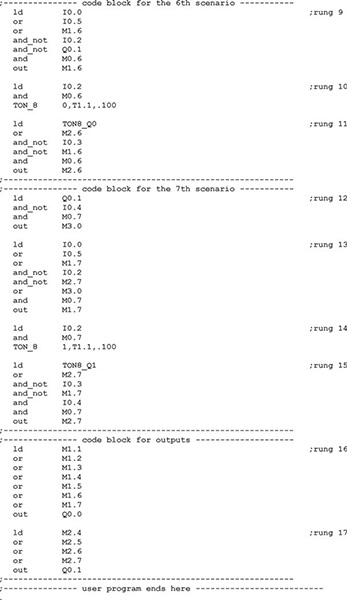
FIGURE 15.18
The user program of UZAM_plc_16i16o_ex41.asm.


FIGURE 15.19
The ladder diagram of the user program of UZAM_plc_16il6o_ex41.asm.
11.2, 11.1, and 11.0 select one of the outputs, and that particular output represents one of the scenarios as shown in Table 15.2. If 11.2,11.1,11.0 = 000 (respectively, 001, 010, 011, 100, 101, 110, and 111), then MO.O (respectively, M0.1, M0.2, M0.3, M0.4, M0.5, M0.6, and M0.7) is set to 1. When MO.O = 1, none of the scenarios are selected. When M0.1 (respectively, M0.2, M0.3, M0.4, M0.5, M0.6, and M0.7) is set, the code block for the first (respectively, second, third, fourth, fifth, sixth, seventh) scenario is activated, shown in rung 2 (respectively, 3; 4; 5 and 6; 7 and 8; 9, 10, and 11; 12, 13, 14, and 15). In this example, in order to operate the motor backward and forward, PLC outputs QO.O and Q0.1 are used as shown in rungs 16 and 17, respectively.