
Chapter 8. Data Center Networks Design
The data center network (DCN) is the primary element interconnecting the various components that all collectively comprise a data center. These components include the following computing, application, storage, and security nodes and services, where scalability, resiliency, security, and performance are the most common fundamental considerations of a successful DCN design.
This brief definition of a DCN emphasizes the important role of the data center’s network infrastructure. In fact, all the communications between applications and services into and out of the data center are steered and carried by the network. As a result, any network availability or capacity issue within the underlying network infrastructure will impact the overall data center responsiveness, even if you have the best network overlay, servers, and application designs in the world. It is exactly like a building with a weak foundation; it cannot scale and be developed reliably, even if it has very promising architecture. For this reason, the data center’s design and architecture must be business driven. All the business’s requirements (its vision, continuity, and service priorities) should be taken into account when architecting a data center network, regardless of whether it is an enterprise data center or a service provider data center.
From a business point of view, the data center is the place where the business stores its data and applications; the data center houses the most critical assets of today’s businesses. Sometimes, the data center even represents the core revenue source of the business, such as hosting data center providers (like software as a service [SaaS] and infrastructure as a service [IaaS] providers). Therefore, the design of a data center ideally should always offer a flexible and reliable design capable of accommodating the evolutions of business requirements and market trends. In addition, one unique and challenging design aspect of DCNs is that to produce a successful business-driven DCN design, you must connect with multiple players within the organization. These players usually belong to different teams, such as the server team, the storage team, the applications team, and the security team. Ideally, the input from these teams should drive the overall data center design, including the network.
This section starts by covering the traditional way of designing DCNs. It then covers the drivers and design considerations of the next generation of data centers, and how yesterday’s data centers are not architected to meet today’s modern data center requirements. This chapter also discusses the design options and challenges of modern data center interconnect solutions.
Note
This chapter, like other chapters in this book, covers the various architectures, protocols, and technologies used by traditional and today’s data centers regardless of whether they are not recommended or whether they are commonly used and highly recommended. After all, the reality is that organizations may have considered some of these technologies or design architectures during a time when their business and application requirements differed from today’s requirements. In addition, technologies are always in evolving state; this implies that what was considered a best practice or fit for any given design yesterday will probably not be the case for today’s data center design. Consequently, network designers must be aware of the various design options and technologies and have a good understanding of the strengths and weaknesses of each to be able to evaluate current designs and to suggest design optimization or a complete redesign (always taking into account, of course, the different design requirements, starting from business and application requirements all the way up to the technical traffic flow and routing).
Traditional Data Center Network Architecture
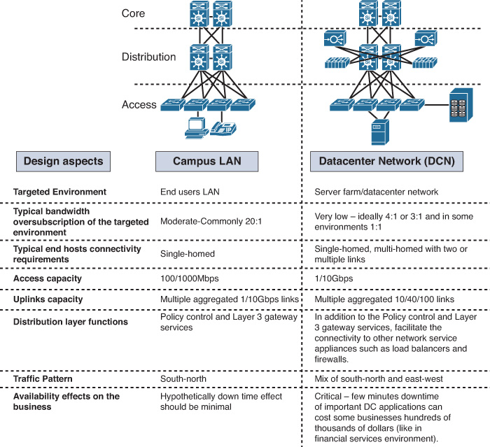
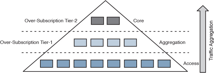
During the past decade, the classic three-tier network architecture has been the predominant network architecture for mid- and large-scale data centers, because this multitier siloed approach offered the desired level of design flexibility, availability, and performance for the various application and server requirements at that time. The overall architecture of a DCN, at a high level, is built on the same concept as the hierarchal network architecture discussed earlier in the enterprise campus section in this book, which usually consists of the core, distribution, and access layers. A common question with regard to the classic three-tier design is this: How does a three-tier DCN design differ from a typical three-tier campus LAN design? Although these two designs follow similar concepts and architecture (for example, they both employ the concept of hierarchal network architecture), they are not identical in their detailed design requirements. This is summarized in Figure 8-1.
STP-Based Data Center Network Architecture
As discussed earlier, there is not a significant difference between the overall architecture of a classic three-tier DCN and the campus design (at a high level). Therefore, all the Spanning Tree Protocol (STP) and Layer 2 considerations discussed in Chapter 2, “Enterprise Layer 2 and Layer 3 Design,” apply here. The only crucial difference is that in a DCN you need to consider the deployment model and failure scenarios for the services provisioned at the data center distribution layer. This is because, in most cases, these services (either service module or appliance based) work in active-standby or active-active modes. In these modes, Layer 2 communication is almost always required between these services across the upstream distribution layer nodes.
If the network, and Layer 2 in particular, was not designed to properly take the connected services to the distribution layer nodes into consideration, the network will most likely face a dual-active or split-brain situation during some failure scenarios. This usually occurs when two service appliances (such as firewalls), operating in active-standby mode, lose communication with each other. As a result, each device thinks that it is the only active device. (The active firewall will continue in active mode, and the standby firewall will move from standby to active mode as well.) Both firewalls handling traffic independently (operating in dual-active mode) is highly undesirable and dangerous because the risk of asymmetrical connection failure is extremely high, as shown in Figure 8-2.
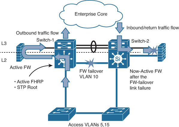
In Figure 8-2, a loop-free U topology is used. In case of L2 link failure between the two distribution switches that carry the data center firewall failover VLANs, both firewalls will be in active mode (split-brain). First Hop Redundancy Protocol (FHRP) active will continue to be on switch 1 because the heartbeat messages flow through the access switch, which means outbound traffic flows through distribution switch 1. If inbound traffic from the core arrives at the distribution switch 2 during this failure scenario, it attempts to flow through the now-active firewall. Traffic will be dropped because of this failure because the now-active firewall has no state information of this session. This issue can be temporarily fixed by enforcing all the inbound traffic to flow via the active FHRP switch. Nonetheless, the main reason behind this example is to highlight the different considerations when designing Layer 2 for a data center compared to a typical campus LAN. Even though the overall topologies and features are similar to some extent, the functions and traffic flow are normally more complicated in DCNs.
As a general rule, to achieve the highest capacity in DCNs, always select the technologies and techniques that provide you with the maximum possible number of forwarding paths (taking into account that too much redundancy might not always be a good idea). Therefore, multichassis link aggregation architecture (mLAG)and Clos fabric architectures, from an L2 design point of view, are always preferred over traditional STP.
The influence of introducing network service security appliances, such as firewalls and load balancers, into the data center aggregation layer is critical. It must be seriously considered, along with all the possible failure scenarios, when contemplating an STP-based access-distribution Layer 2 topology. This is applicable for both services, which are either module or appliance based.
mLAG-Based Data Center Network Architecture
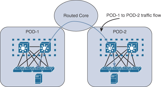
As discussed earlier in this book, the mLAG architecture keeps STP in place but overcomes its shortcomings by using mLAG functions with switch clustering enabled at the aggregation layer. Compared to an STP-based design, this architecture offers a more flexible and resilient DCN with significant performance and bandwidth capacity optimization. However, scalability (scale-out) is one of the main concerns with this architecture for large-scale data centers that are based on virtualized workloads. Typically, only two aggregation switches can be clustered to serve as one logical device for the downstream switches (access switches). Consequently, access switches connecting to different clustered upstream aggregation switches have to communicate via the Layer 3 core, which may break the requirements of seamless end-to-end Layer 2 VM mobility or distributed workloads across different points of delivery (PODs), as shown in Figure 8-3.
Next-Generation Data Center Network Design
This section discusses the different design options and protocols used in today’s modern DCNs and the drivers toward adopting these new architectures.
Data Center Virtualization and Cloud-Based Services Overview
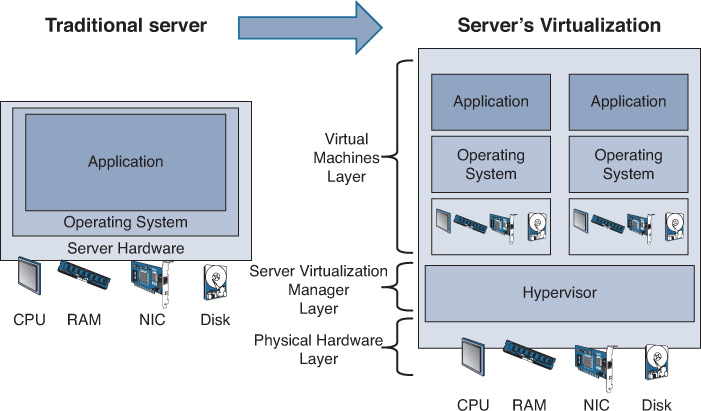
In the world of servers, the term virtualization refers to the ability to run multiple operating systems and application instances on a single physical server. The abstraction layer of virtualization is usually provided by software (OS) known as a virtual machine manager (VMM), also commonly known as a hypervisor. The VMMs/hypervisors provide the capability to control and manage multiple operating systems and emulate a dedicated environment to each server over one shared physical system using its hardware resources. As shown in Figure 8-4, the shared resources include CPU, memory, and network cards, which separate computing environments from the actual physical infrastructure. This approach has proven to reduce costs (capital expenditure [capex] and operating expenditure [opex]), and it enables IT and businesses to gain increased efficiency and flexibility from the existing computing hardware.
It is important for network architects and designers to understand the logical difference between the terms change and transformation. Change always takes the past as a foundation, and modifies it in a manner to make it more optimized; more scalable or more reliable. However, transformation refers to something new, such as designing a future goal or target, and then achieving it. Unlike change, transformation does not mainly rely on something that already exists, and then modifying it so as to make it more secure or reliable; instead, it’s more about creating a concept that does not exist already (new)1.
1. http://theprimes.com/change-vs-transformation/
Based on that, the concept of cloud or cloud computing in the world of data centers is a transformation in how data centers are designed and operated. In fact, it is a completely new era in the world of data centers. Technically, cloud computing further leverages the concept of server virtualization by adding an additional layer of virtualization and service abstraction. This offers on-demand network and service access to a shared pool of resources. These resources usually include network, storage, and computing resources, which ultimately enable multitenancy capabilities in the data center. Also cloud services incorporate self-service portals, automation, and orchestration to more effectively leverage these shared pools of resources.
Cloud computing also provides an X-as-a-S offering, such as IaaS and ITaaS. This is when scalable IT-related capabilities are provided “as a service,” which allows more elastic and on-demand service provisioning and access. Furthermore, cloud services can help to transform IT from being a capex model to an opex model, which will help organizations to better control costs. In sum, virtualization is fundamental to enabling cloud services in a data center. Virtualization generally takes the following forms:
![]() Server virtualization
Server virtualization
![]() Network virtualization
Network virtualization
![]() Storage virtualization
Storage virtualization
![]() Management virtualization and cloud orchestration
Management virtualization and cloud orchestration
This chapter focuses on network virtualization and the new trends and architectures of next-generation data centers, which are propelling the change in DCN designs, approaches, and technologies.
That said, this does not mean that each and every single data center design needs to be transformed to a cloud-based DC model. Doing so depends entirely on the business goals, model, vision, cost (capex versus opex), and various other requirements (such as elastic business-continuity requirements), which in turn will help you to identify the current and anticipated future size of the organization and its DC network and understand mission-critical applications, the services provisioning model, traffic pattern, and so on. These collectively can help you to decide whether it is more feasible to “change” the existing DC design and architecture to a more optimized one or to “transform” it to a completely new DC model/architecture.
Drivers Toward New Fabric-Based Data Center Network Architectures
It is commonly known that the DCN sits at the core of the IT infrastructure. Therefore, it is crucial to understand how IT can deliver services and value back to the business. The new business demands and technology trends are changing the role of IT and introducing new challenges to the availability of applications; yesterday’s data centers were not designed to address these challenges, which include mobile and virtualized workloads, cloud applications, big data analytics, and dynamic policy provisioning. In this new environment, it is obvious that bandwidth demand is much higher and that the traffic pattern is unpredictable as compared to traditional data centers. Traditionally, the DCN is based on the classic three-tier hierarchy, as shown earlier in Figure 8-1.
Typically, the classic three-tier architecture introduces significant oversubscription and blocking architecture, which is unsuitable for the requirements of today’s workloads and application requirements. This is simply because the higher the traffic moving in the network hierarchy (bottom-top) of the multitiered network, the more bandwidth sharing there will be among the nodes in the lower tiers (bandwidth aggregation), as shown in Figure 8-5.
Note
Oversubscription and blocking in traditional architectures can be described as follows:
Oversubscription is when the ingress capacity exceeds the egress capacity. For example, for 48x 10G attached servers, the access switch needs at least 480 Gbps of port capacity toward the upstream or distribution layer to provide 1:1 oversubscription (1:1 here meaning zero or no subscription). However, if the access switch has only 2x 10G uplinks, in this case the oversubscription is 24:1. Although not every network is required to provide 1:1 performance, oversubscription needs to be minimized in modern large-scale DCNs (for example, ideally 4:1 or 3:1) [55]. Blocking is a situation, at a device level, caused by oversubscription, which can lead to network queuing. As a result, the overwhelmed node, such as a distribution switch handling inter-POD or rack traffic, will start blocking the new traffic flows. Ideally, during the planning phase, the network architect or designer should obtain enough information (such as baseline conditions and application traffic patterns) before attempting to define any oversubscription standard or deciding whether a nonblocking DCN architecture is required.
Note
As a network designer, always ask for information that helps you to derive the DCN design decision based on the requirements of the systems and mission/business-critical applications hosted in the data center.
The term POD (point of delivery) represents a standardized structured block constructed primarily of network, computing, and storage resources. In virtualized data centers, this concept serves the foundation of achieving standardized design modularity that can support high scale-out and scale-up heterogeneous workload requirements; this will ultimately help in minimizing the overall design and operational complexity.
A move from the traditional architecture to a more flexible, high-speed (nonblocking), low-latency, and agile network architecture was required to accommodate these evolutions and the transformation of modern data center requirements using fabric based infrastructure.
Fabric is defined by Gartner, Inc. as “a set of compute, storage, memory and I/O components joined through a fabric interconnect and the software to configure and manage them.”2
2. http://www.gartner.com/it-glossary/fabric-computing
The new switch fabric concepts and architectures came into the picture to meet today’s data centers trends and requirements, which primarily derived from the following factors:
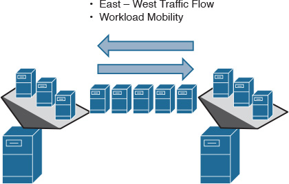
![]() Traffic pattern: Server virtualization and cloud-based services are a game changer in data center design concepts and architectures, in particular the traffic flow within a data center and between interconnected data centers. Traditionally, traffic flow was mainly north-south, sourced from internal or external users to the application hosted in the data center. In contrast, modern data centers are moving toward a more distributed workload and workload mobility, taking advantage of the vitalization concepts and distributed virtual machines (VMs) across one or multiple data centers between hosts, as shown in Figure 8-6. Therefore, the traffic pattern is becoming more of a combination of east-west (server-to-server) and north-south (client-server), which makes it unpredictable. As a result, the traditional three-tier DCN design is becoming more of a limiting factor for the new server and application traffic requirements (increased east-west traffic flow).
Traffic pattern: Server virtualization and cloud-based services are a game changer in data center design concepts and architectures, in particular the traffic flow within a data center and between interconnected data centers. Traditionally, traffic flow was mainly north-south, sourced from internal or external users to the application hosted in the data center. In contrast, modern data centers are moving toward a more distributed workload and workload mobility, taking advantage of the vitalization concepts and distributed virtual machines (VMs) across one or multiple data centers between hosts, as shown in Figure 8-6. Therefore, the traffic pattern is becoming more of a combination of east-west (server-to-server) and north-south (client-server), which makes it unpredictable. As a result, the traditional three-tier DCN design is becoming more of a limiting factor for the new server and application traffic requirements (increased east-west traffic flow).
![]() Cost: Because of the limitations of the classic multitier architecture, it will be necessary to have a larger number of switches with a larger number of ports (scale up) to handle the increase in the data center size. This will lead to extra cost (capex) and a more complicated design, which will increase the operational cost (opex) as well.
Cost: Because of the limitations of the classic multitier architecture, it will be necessary to have a larger number of switches with a larger number of ports (scale up) to handle the increase in the data center size. This will lead to extra cost (capex) and a more complicated design, which will increase the operational cost (opex) as well.
![]() Reliable scalability: Server virtualization and VM mobility increase demand on the network infrastructure to support the ability to scale-out, considering the extremely increased number of virtual hosts compared to traditional data centers. Take, for example, an access switch that has 16 physical hosts connected to it. Traditionally, there will be 16 servers to handle; with the server virtualization concept, if these hosts have 10 VMs each, this access switch needs to handle 160 servers. Typically, these 16 physical hosts, if they used to be connected over a 1G port, now must each be connected over a 10G access port. In other words, this tremendous increase in the number of hosts (virtual) and traffic volume needs a new architecture that is built to scale without compromising bandwidth efficiency.
Reliable scalability: Server virtualization and VM mobility increase demand on the network infrastructure to support the ability to scale-out, considering the extremely increased number of virtual hosts compared to traditional data centers. Take, for example, an access switch that has 16 physical hosts connected to it. Traditionally, there will be 16 servers to handle; with the server virtualization concept, if these hosts have 10 VMs each, this access switch needs to handle 160 servers. Typically, these 16 physical hosts, if they used to be connected over a 1G port, now must each be connected over a 10G access port. In other words, this tremendous increase in the number of hosts (virtual) and traffic volume needs a new architecture that is built to scale without compromising bandwidth efficiency.
![]() High flexibility: The emergence of virtualized and cloud-based data centers requires networks with architecture that supports simple and flexible automated provisioning, such as application programming interface (API) integration with cloud orchestration systems.
High flexibility: The emergence of virtualized and cloud-based data centers requires networks with architecture that supports simple and flexible automated provisioning, such as application programming interface (API) integration with cloud orchestration systems.
![]() Ultra-low-latency network: Today, some environments require high-frequency trading, such as in financial services (where thousands of trading transactions are expected to be performed in a few seconds), which can be a big challenge when traditional data center platforms and design are used. Consequently, to meet the requirements of this type of environment, you need a network architecture that can support ultra-low-latency forwarding and a nonblocking switch fabric architecture that can forward packets in full size within microseconds. These are required to satisfy the needs of this type of environment, in which the extremely low-latency, high-performance, high-bandwidth and reliable transport form the foundation of today’s high-frequency trading DCN
Ultra-low-latency network: Today, some environments require high-frequency trading, such as in financial services (where thousands of trading transactions are expected to be performed in a few seconds), which can be a big challenge when traditional data center platforms and design are used. Consequently, to meet the requirements of this type of environment, you need a network architecture that can support ultra-low-latency forwarding and a nonblocking switch fabric architecture that can forward packets in full size within microseconds. These are required to satisfy the needs of this type of environment, in which the extremely low-latency, high-performance, high-bandwidth and reliable transport form the foundation of today’s high-frequency trading DCN
Modern data center architectures are moving from the classic three-tier architecture toward flatter fabric-based architectures, which are specifically built and architected for the new requirements of the next-generation data centers and to overcome all the limitations discussed earlier. Moreover, the any-to-any, nonblocking fabric architecture enables IT to align with the business needs and priorities by delivering tangible outcomes. These outcomes include a reduction in the number of full server I/O adapters (support of server virtualization and unified I/O), significant enhancement of the reliable scalability of the network, and the simplification of cabling. Furthermore, power and cooling costs are lowered by the elimination of unnecessary switching infrastructure used by the traditional data center architecture, and overall operational cost is also reduced.
Modern Data Center Network Architectures and Overlays
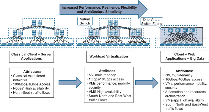
As discussed earlier, the traditional three-tier DCN design has many limitations when used in a virtualized or cloud-based data center with workload mobility, high-bandwidth capacity, and fast forwarding requirements, simply because at each tier in the network, the uplink bandwidth is distributed across the next-higher tier. Consequently, the more tiers traversed by traffic between servers (east-west), the greater the potential for bandwidth shortage (traffic aggregation) associated with increased latency and limited scale-out capabilities. Therefore, a new and more scalable network architecture, combined with a switch fabric architecture capable of providing any-to-any nonblocking connectivity, is required to overcome these limitations. Figure 8-7 shows the evolution of DCN architectures.
Consequently, modern data center fabrics should accelerate the deployment of applications and meet development and operations (DevOps) needs by
![]() Eliminating any dependencies on traditional protocols, such as STP
Eliminating any dependencies on traditional protocols, such as STP
![]() Offering fast forwarding underlay for multidimensional traffic (high bisectional bandwidth)
Offering fast forwarding underlay for multidimensional traffic (high bisectional bandwidth)
![]() Providing optimized scalable forwarding (scaling forwarding tables and segments)
Providing optimized scalable forwarding (scaling forwarding tables and segments)
![]() Providing cloud integration and automated provisioning (such as API integration with cloud orchestrator systems)
Providing cloud integration and automated provisioning (such as API integration with cloud orchestrator systems)
![]() Providing virtualized networking to support mobility and virtual devices across the DCN
Providing virtualized networking to support mobility and virtual devices across the DCN
![]() Providing a reliable scale-out capability
Providing a reliable scale-out capability
At the time of this writing, there were a few modern data center fabric architectures, such as single virtual fabric and Clos architecture. This section focuses on the most common and proven architecture in today’s data centers, which is the Clos architecture. Different design considerations and options are discussed, as are the drivers of each that help network designers select the right architecture to offer modern DCNs a higher degree of flexibility, reliability, scalability, and performance.
Clos Architecture
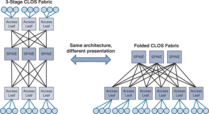
Clos architecture offers a nonblocking architecture based on multistage topology, which can maximize the overall network performance by increasing the available bandwidth to higher than what a single node can provide. The mathematical theory of this architecture was initially created by Charles Clos in 1953, hence the reason it is called Clos. In a nutshell, this architecture is based on associating each output with an input point. In other words, the number of outputs equals the number of inputs, or there is precisely one connection between nodes of one stage with those of another stage [55]. Figure 8-8 illustrates this architecture that offers zero oversubscription (1:1) where a 3-stage Clos topology is used to connect 18 host (edge ports) using 3x of 6 port switches in each stage.
Note
Although the Clos architecture can offer scalable 1:1 (zero) oversubscription, this level of oversubscription is rarely required. Typically, 4:1 or 3:1 offers an efficient level of oversubscription with modern data centers that are built on 10/40/100G Ethernet. In fact, application and service requirements should drive the required level of oversubscription during the planning phase, taking into account the anticipated traffic load.
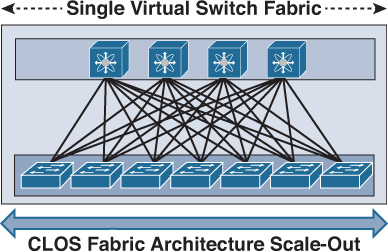
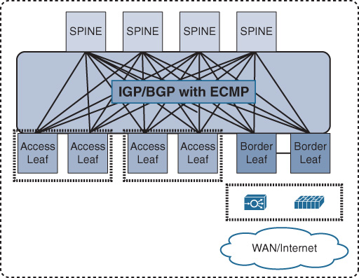
This architecture can be considered a two-tier hierarchy, in which the access layer switches are called leafs and the aggregation layers are called spines. With this two-tier leafs and spines architecture, each leaf switch is connected to every spine switch on the aggregation layer, which makes the DCN architecture flatten and eliminate bandwidth aggregation/oversubscription, because of bandwidth being the same at every tier. As a result, this architecture offers a high degree of network redundancy and a simplified design, and supports a large volume of bisectional traffic (east-west), as shown in Figure 8-9. Moreover, it can support multipathing, which can efficiently use network resources to support more leaf switches. Network designers can either consider scaling up, scaling out spine switches, or moving to a five-stage Clos topology for significantly larger scale DC networks.
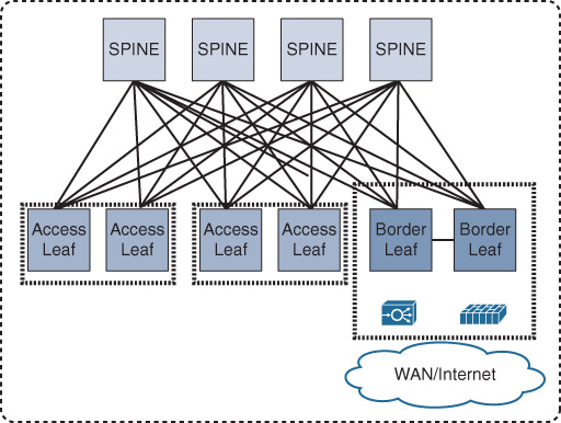
Unlike traditional data center architecture where Layer 3 gateway services and other network and security services are provided by the aggregation layer, in Clos (spines and leafs) architecture, the role of the spine is only to forward traffic between the leafs in the same manner that P routers work in a Multiprotocol Label Switching (MPLS) network. Furthermore, DC services and Layer 2 and Layer 3 demarcation points are moved in the architecture down to the leaf (also known as the border leaf), taking advantage of the high capacity and performance of the bisectional bandwidth of this architecture, as shown in Figure 8-10. As a result, additional spine switches can be introduced to the network to increase its scalability and reliability without any changes required to network and security services. In other words, unlike the traditional design, Clos is not tied to a pair of aggregation switches only. Therefore, Clos offers the optimal architecture for today’s multitenant virtualized and cloud-based data centers.
Note
The definition of a tenant varies based on the targeted business and the data center environment. For example, in an enterprise environment, the tenants can be the different departments or business units (like in ITaaS environment), whereas in a cloud-hosting service provider, the most typical tenants are the external customers.
Clos Transport Protocols
To provide any-to-any nonblocking seamless connectivity and eliminate the reliance on STP, Clos fabric architectures rely on transport protocols that offer the ability to use all the available links between any two leaf switches over the intermediate spine nodes (equal-cost multipath routing [ECMP]).
Overlay Transport
In fact, network overlays are the representations of virtual networks of interconnected nodes that share an underlying physical network, allowing deployment of applications that require specific network topologies without the need to modify the underlying network. Ultimately, this can offer to the Clos fabric design the optimal level of flexibility, scalability, and performance required by today’s modern data centers.
At the time of this writing, the following are the primary protocols considered by the majority of modern data centers to offer scalable and flexible ECMP forwarding over the Clos fabric architecture:
![]() MAC-in-MAC
MAC-in-MAC
![]() MAC-in-IP
MAC-in-IP
![]() MPLS based
MPLS based
MAC-in-MAC
As mentioned earlier in this chapter, a primary goal of the Clos architecture is to eliminate any reliance on Layer 2 STP and optimize traffic distribution in multiple directions. To achieve this and facilitate the MAC-in-MAC encapsulation to work over all available paths, Intermediate System-to-Intermediate System (IS-IS) is used instead of traditional STP, because it is actually a Layer 2 routing protocol that does not rely on IP for carry frames. Therefore, IS-IS routing is used to distribute link-state information and to calculate the shortest paths through the Clos network (usually between the multiple leaf stages via the spine nodes) to form the underlay of the Clos fabric network.
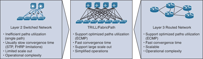
MAC-in-MAC, however, can be achieved using different protocols, such as IETF TRILL (Transparent Interconnection of Lots of Links), IEEE 802.1aq SPB (shortest path bridging), or Cisco FabricPath. Furthermore, TRILL/FabricPath brings the stability and performance of Layer 3 routing to Layer 2 switched networks, which offer a highly agile and reliable Layer 2 fabric that supports high scale-out DCN design requirements,3 as shown in Figure 8-11.
3. “Scale Data centers with Cisco FabricPath,” http://www.cisco.com
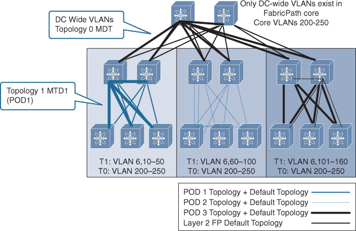
Although TRILL and FabricPath are similar conceptually, FabricPath offers a more flexible and scalable design than TRILL when applied to the DCN. For example, the conversational MAC address learning of FabricPath offers a higher degree of MAC learning and forwarding efficiency to large-scale networks with a large number of MACs (such as a virtualized DC environment). In addition, FabricPath allows network designers and data center operators to optimize DCN efficiency and manageability by considering the FabricPath multitopology design, as shown in Figure 8-12.
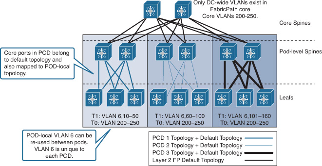
As shown in Figure 8-12, the core is not required to hold all the VLANs from different downstream PODs if they are not used for inter-POD communication (local to the POD only). It can also be feasible in scenarios such as migration designs, VLAN localization, VLAN reuse, traffic engineering, and security. Network designers can take advantage of this multitopology architecture to optimize not only unicast but multidestination as well. This optimization is achieved by isolating and containing BUM (broadcast, unknown unicast, and multicast) traffic of the POD’s local VLANs with the POD boundary without flooding this traffic unnecessarily to the core and other PODs, because each FabricPath topology can have its own multidestination tree (MDT), as shown in Figure 8-13.
Furthermore, FabricPath enhances FHRP gateway services by offering the ability to provide four active HSRP peers in active-active mode (also known as anycast HSRP), whereas TRILL forwards traffic based on the traditional active-standby mode, as shown in Figure 8-14. Traffic forwarding based on the traditional active-standby mode usually offers lower forwarding efficiency and higher convergence time in the event of an FHRP gateway failure.
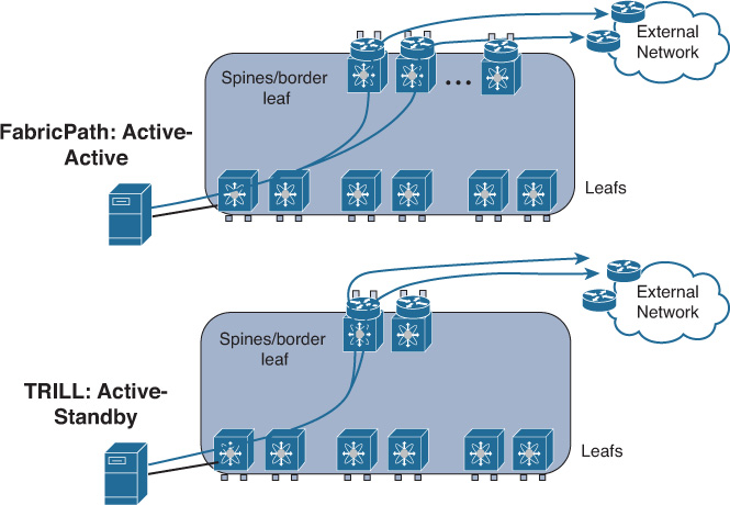
With TRILL/FabricPath design, the Layer 3 gateway services can be deployed either at the spine nodes or can be moved to the border leaf nodes. Therefore, in Figure 8-14 the spine nodes are labeled as spines/border leaf.
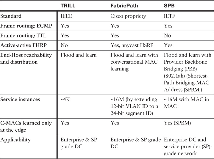
Table 8-1 highlights the primary differences between FP, TRILL, and SPB.
Note
The Shortest Path Bridging VLAN ID (SPBV) version of SPB is Q-in-Q rather than MAC-in-MAC.
MAC-in-IP
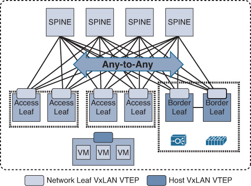
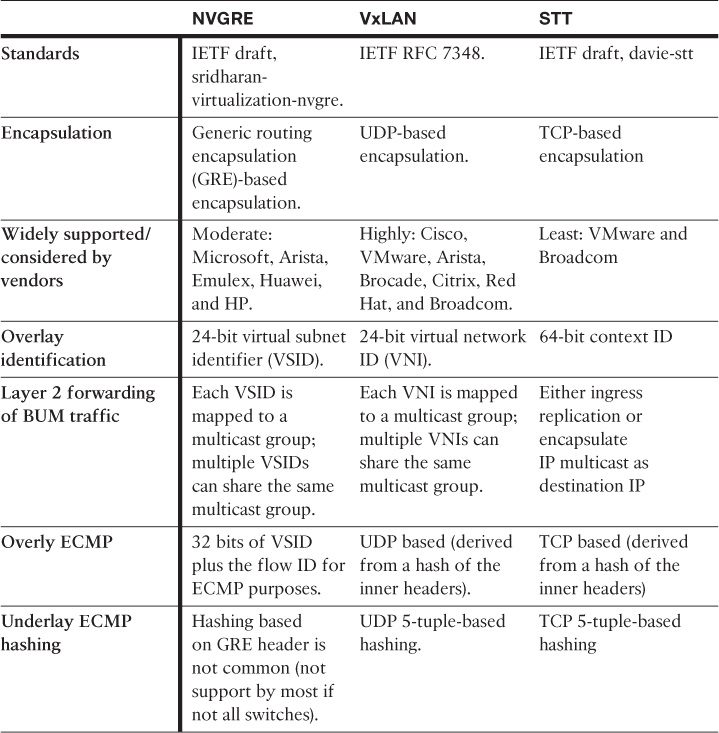
With MAC-in-IP, it is obvious that the transport will be IP based from the network underlay point of view. Typically (not always), designing a Clos with MAC-in-IP overlay will rely on IS-IS to form the underlay of the Clos fabric network (ECMP). However, unlike MAC-in-MAC, the concept of MAC-in-IP overlay transport is based on the formation of virtual Layer 2 topologies on top of a physical Layer 3 network (IP encapsulation) combined with the concept of virtual network identifier, which is primarily used to forward frames to the required virtualized network context. Furthermore, MAC-in-IP overlay provides network based overlay, and it is also considered to be a host-based overlay solution offering multitenancy at scale with more simplified and automated workload provisioning capabilities. Figure 8-15 illustrates this concept with VxLAN applied as the MAC-in-IP overlay and the VxLAN tunnel endpoints (VTEPs) created at different levels.
At the time of this writing, the following are the primary protocols used for this purpose:
![]() Network Virtualization Using Generic Routing Encapsulation (NVGRE)
Network Virtualization Using Generic Routing Encapsulation (NVGRE)
![]() Virtual Extensible LAN (VxLAN)
Virtual Extensible LAN (VxLAN)
![]() Stateless Transport Tunneling (STT)
Stateless Transport Tunneling (STT)
Table 8-2 compares the characteristics of these protocols.
Although host-based overlay may offer capabilities that optimize the overall architecture and its flexibility with regard to workload mobility and automated provisioning, a robust and reliable underlay transport still forms the foundation of this overlay. If there is any inefficiency within the underlay design or performance, it will be reflected directly on the overlay efficiency as well. Therefore, a successful overlay DCN design must be architected over a reliable networked infrastructure that supports the desired level of resiliency and performance.
Note
The Cisco Application Centric Infrastructure (ACI) provides optimized traffic forwarding over a Clos architecture associated with flexible network-based VxLAN forwarding where each leaf performs encapsulation-normalization, which offers the freedom for DC operators and server administrators to consider any type of host-level tagging, such as 802.1Q, network virtualization using GRE (NVGRE), VxLAN, or untagged.
Today’s modern and cloud-based data centers are moving rapidly toward the concept of a centralized control plane that offers an abstracted centralized view of the network and can manage traffic and deploy services centrally (manually and automatically provision services) to meet today’s data centers needs, which are mainly built around simplicity, high-speed forwarding, and fast services provisioning with automation without having to touch each individual network node in the forwarding plane across the DCN. This concept is known as software-defined networking (SDN). Although SDN is beyond the scope of this book, it is highly recommended that network designers (regardless preparing for the CCDE or not) have a good understanding of this concept and how it can simplify and optimize virtualized and cloud-based data center designs.
MPLS Based
Although other protocols discussed earlier in this chapter provide end-to-end path separation optimally by using different mechanisms, with MPLS the design can be feasible for scenarios requiring integration with other MPLS domains (for instance, data centers that belong to MPLS L3VPN providers that offer hosting services to their customers as well). Therefore, enabling MPLS L3VPN across the DCN can facilitate end-to-end MPLS L3VPN integration and offer seamless access with a scalable architecture.
That said, using MPLS across the leaf and spine architecture is becoming less common in today’s DCNs as other protocols and overlay technologies such as VxLAN offer more simplified and flexible provisioning and integration with cloud orchestration (host based and network based) at a high scale. Therefore, data center operators can consider any hybrid approach, where you can use one of the protocols discussed earlier across the DC Clos fabric, such as TRILL or VxLAN, while MPLS L3VPN can be extended from the Clos (border leafs) at the DC edge, as shown in Figure 8-16. In addition, the flexibility and efficiency of this design offers a simplified migration approach for data center operators to move from a pure MPLS-based DC to FabricPath or VxLAN based while retaining MPLS VPN enabled at the data center Clos fabric border leafs. In addition, this approach offers a seamless integration with other MPLS domains such as MPLS L3VPN, as shown in Figure 8-16.
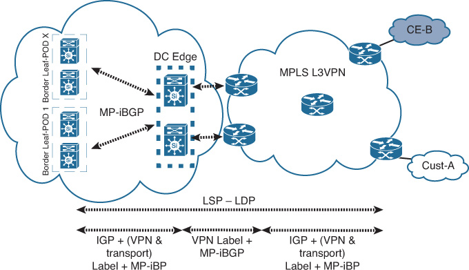
Note
If the leaf switches do not support MPLS, virtual routing and forwarding (VRF), or Multiprotocol Border Gateway Protocol (MP-BGP), MPLS can enabled at the DC edge nodes only to interconnect with other MPLS L3VPN domains. This approach requires extending the relevant DC VLANs to the DC edge nodes that will operate like an SP provider edge (PE) nodes, which in turn will increases its operational complexity.
MPLS over Clos is still a valid and doable design option; however it depends on the requirements and situation whether to consider it; see Table 8-3 for more detail.
Note
In this design, Layer 2 communications between different PODs can be facilitated by considering inter-POD L2VPN.
Note
In general, overlays can lead to increased operational complexity, because normally these overlays will require network operators to investigate the mapping of the virtual topology on top of the physical topology.
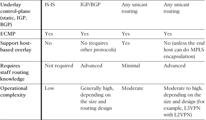
Layer 3-Based Transport (Nonoverlay)
This design model is based on the concept of using Layer 3 routing only to handle the packet forwarding across the Clos fabric network by extending Layer 3 routing across the leaf and spine nodes, as shown in Figure 8-17. Therefore, this model is not actually overlaid. Instead, it is based on an end-to-end routed network from leaf to leaf (top-of-rack [ToR] switches) over the spines. This design model offers an increased level of network scalability and stability by limiting Layer 2 flooding domains to the minimum (usually up to the ToR/leaf switches).
Furthermore, this design model facilitates to a high degree Clos architecture scale-out in large-scale DCNs. In addition, using one unified control plane protocol can significantly simplify overall network manageability and troubleshooting. Therefore, this routed Clos fabric architecture can support large-scale data centers that host tens of thousands of systems (physical or virtual). However, this design approach is more suitable for large-scale data centers where the highest priority is a stable and scalable network that can host extremely large number of servers (instead of using large Layer 2 adjacencies across the network) [61]. However, the degree of the network scalability and stability with this architecture is still dependent on the characteristic of the used Layer 3 control plane protocol and its design.
Typically, you can use either an interior gateway protocol (IGP) (such as link-state routing protocols) or BGP as the control plane protocol to provide the control plane routing and forwarding. However, link state requires some fine-tuning to the protocol to optimize its performance and reduce the amount of link-state flooding and processing overhead over such a topology (Clos). In addition, the shortest path first (SPF) algorithm limitations on Clos topology can add some design and operational complexities, because each leaf might appear as a transit path to reach a spine or another leaf switch.
In contrast, using BGP as the control plane protocol within the data center over the Clos fabric architecture, in particular external BGP (eBGP), can offer a more controlled, simplified, and scalable routed Clos fabric design as compared to IGP. However, this approach may introduce some limitations around network convergence time. As highlighted earlier, this design model is more suited for environments that do not require extending Layer 2 across different leaf nodes or PODs; therefore, if VM mobility is required in this architecture, you can use a MAC-in-IP overlay, which means another protocol to manage, and this translates into higher design and operational complexity in this case.
Table 8-3 compares the different transport options that you can use with the Clos DCN architecture covered in this section.
Dynamic fabric automation is a variation of the Clos architecture that offers automation and API northbound integration with the cloud orchestrator. For instance, with Cisco Dynamic Fabric Automation (DFA), when a VM is provisioned, the DFA leaf node autodetects the VM, and pulls and applies the policies associated with the VM on the connected port. The fabric tracks a VM and moves these port profiles within the fabric automatically [38]. The Cisco DFA fabric can apply this automation workflow to a similar physical server.
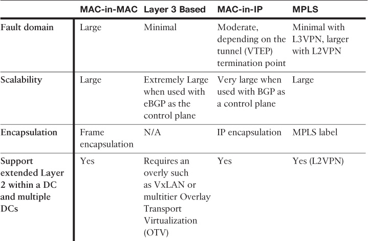
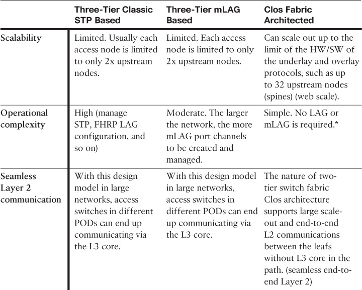
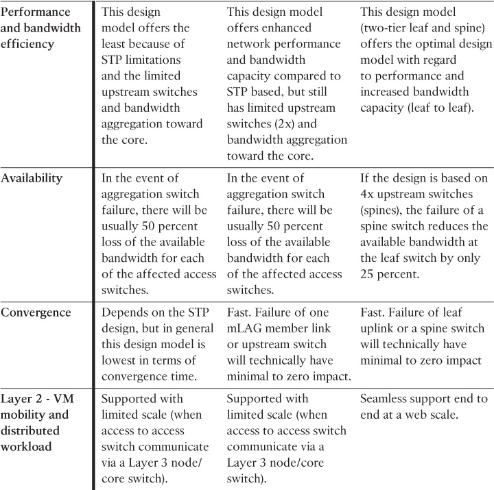
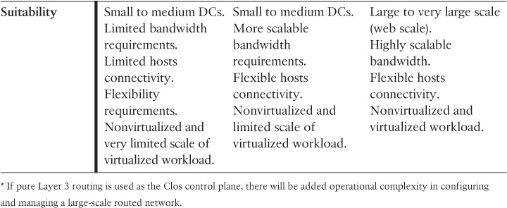
Comparison of Data Center Network Architectures
Table 8-4 compares the primary characteristics of each of the most common design models of DCNs available today and discussed earlier in this chapter.
Network designers might sometimes need to integrate one of the modern DC designs discussed here, such as TRILL or VxLAN, with a DC environment that is based on a traditional design (STP based), which is common in migration scenarios. Therefore, in this type of scenario, one of the primary design principles that must be considered is that flooding domains (failure domains) have to be minimalized and contained. For instance, the classic Layer 2 VLANs of an existing DC LAN can terminate at the VxLAN gateway node that performs bridging and routing between the different DCN domains.
Data Center Interconnect
The concept of distributing business applications and services across geographically dispersed data centers has existed for years; it is not a new concept or a design approach. Primarily, it is driven by the need to maintain business resilience and provide reliable disaster recovery (DR) capabilities for the data center IT infrastructure and resources. The emergence of cloud computing has further covered the need for extremely robust network resilience strategies, addressing security, availability, and virtual machine (VM) mobility while maintaining the flexibility and agility of a cloud model. Cloud computing promises to offer services that can have dynamic resource allocation and are accessible from anywhere (over the Internet) in a completely virtualized on-demand environment. Accordingly, the availability of the cloud data center and its elements (network, computing, and storage) are critical to supporting business continuity.
The nature of a cloud data center built on a fully virtualized environment introduces some challenges to maintaining business continuity, in comparison to traditional data centers. For example, the physical components of the cloud data center (computing, network, and storage) may not all be located within the same physical location. Instead, they may be distributed across more than one physical location and interconnected over a transport mechanism that maintains an end-to-end path isolation. To achieve the desired level of data center business continuity, there must be a reliable DR plan and procedures in place.
Businesses and stakeholders are realizing the importance of business continuity. For instance, the loss of connectivity to a data center in a financial services business, for a few minutes, may cost the business hundreds of thousands of dollars. This makes considerations of a DR plan a common business requirement to achieve the desired level of business continuity during and after failure situations. Typically, disasters can be classified based on the degree and geographic coverage of the impact (local, metro, regional, or global) and can result from
![]() Natural catastrophe: Such as fire, flood, or earthquake
Natural catastrophe: Such as fire, flood, or earthquake
![]() System outage: Such as power outage at the Main Distribution Frame (MDF) that provides the external connection to the DC
System outage: Such as power outage at the Main Distribution Frame (MDF) that provides the external connection to the DC
![]() Human error: Such as misconfiguration, which may lead to bringing one or all interconnected data centers into a blackout situation
Human error: Such as misconfiguration, which may lead to bringing one or all interconnected data centers into a blackout situation
Based on the business’s targeted level of continuity and data protection, you can use a different remote DR site model along with the appropriate DR solution. A remote DR site refers to the site to where some or all of the vital business operations and applications can be moved in the event of any outage (whether a planned or unplanned outage). Typically, a DR site is one that is dedicated to the data center’s failover purposes, such as a secondary data center. Nonetheless, sometimes it is expensive for businesses to maintain a dedicated DR site. Therefore, these businesses consider other sites, such as a regional data center, with its primary function being to serve regional remote sites as the primary DC. At the same time, it operates as a DR data center for the centralized or primary data center.
In addition, some public cloud providers offer DR as service (DR-as-a-S). This service is for customers who do not need to build or dedicate a data center. These customers can benefit from this cost-effective approach, because the data center operator does not need to build and maintain cooling, power, cabling, and internal and external network connectivity. Moreover, data center operators that already have their own private cloud can consider what is known as a hybrid cloud. A hybrid cloud is where the DR site can be hosted by one of the public cloud providers as well, for the same purpose, while maintaining connectivity between the two cloud DCs using an intercloud solution.
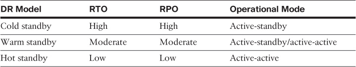
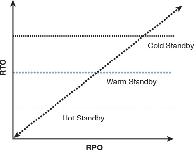
Besides the remote DR site consideration, the DR solution should be selected based on how long the organization can wait for services to be restarted (in particular, the extent to which the business can afford to lose data after the failover happens). Should the business restart in a degraded mode, or must all services be fully available immediately after the switchover? Financial services normally require a recovery time objective (RTO) of less than one hour with a recovery point objective (RPO) equal to zero without a degraded mode [39]. This is a fairly widespread practice so that no transactions are lost. The data center interconnect (DCI) plays a primary role in reaching and delivering these requirements. Table 8-5 compares the typical DR models in terms of the levels of RTO and RPO each model can support; this relationship also shown in Figure 8-18.
Note
Business continuity (BC) is not analogous to DR. Typically, BC should answer the questions of “How can you keep the business running at the recovery site?” and “How can you eventually transfer business functions back to the primary site?” DR answers the question, “How can you recover/move services on the recovery site during and after a disaster or data center failure?” In other words, a DR plan is one component to achieving BC.
Even though the cold standby has high RPO and RTO, it might not be suitable for a business that has systems capable of operating offline and storing data locally then replicating it later to the data center. In other words, network design decisions always depend on the business goals and needs and on the characteristics of the systems and applications used.
Note
Although the focus of this section is on modern data centers based on virtualization and cloud services with VM mobility, all the design options and considerations discussed in this section apply to traditional data centers. In fact, with traditional data centers where little or no virtualization has taken place, the job is much easier because there is no VM mobility. Instead, the main focus is on selecting which DR approach to use, and how L3 routing is designed to address inbound and outbound traffic flow when the interconnected data centers are designed to work in either an active-standby or active-active manner.
Note
BC aims to continue business activities (business as usual) after a disaster or failure. From the network point of view, this goal is to be achieved across two or more data centers where a redundant external network path (communication with the external users WAN, MAN, or Internet) is in place. The subsequent sections assume the external connection to the WAN or Internet is already in place (locally per DC) and focus on the design consideration of the DCI part and how to optimize traffic flows to the different DCs to meet BC goals.
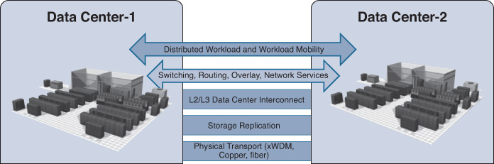
DCI Building Blocks
The following elements are the primary functional components that comprise the DCI building block architecture to provide transport elasticity, flexibility, transparency, and resiliency between two or more sites:
![]() DCI Connectivity
DCI Connectivity
![]() Extended LAN: Provides transparent transport for application and operating system mobility that requires Layer 2 adjacency, such as geoclustering.
Extended LAN: Provides transparent transport for application and operating system mobility that requires Layer 2 adjacency, such as geoclustering.
![]() Layer 3 based: Provides the typical routed connectivity between the interconnected data centers and provides a reliable transport for workload mobility for the systems that support it over Layer 3.
Layer 3 based: Provides the typical routed connectivity between the interconnected data centers and provides a reliable transport for workload mobility for the systems that support it over Layer 3.
![]() Hybrid: This connectivity option is usually based on having a mixture of both Layer 3 and Layer 2 DCI, where the only LAN extension across the DCI is provisioned used for certain VLANs that require Layer 2 extension, while all other subnets will communicate over the DCI using the Layer 3 based DCI model.
Hybrid: This connectivity option is usually based on having a mixture of both Layer 3 and Layer 2 DCI, where the only LAN extension across the DCI is provisioned used for certain VLANs that require Layer 2 extension, while all other subnets will communicate over the DCI using the Layer 3 based DCI model.
![]() Intra and inter-DC routing: Provides remote site and end-user access to the DC resources, such as applications and cloud services, in addition to facilitating the communications between the segmented networks across the interconnected data centers. (Usually each DC should have its own WAN or Internet connectivity to external networks.)
Intra and inter-DC routing: Provides remote site and end-user access to the DC resources, such as applications and cloud services, in addition to facilitating the communications between the segmented networks across the interconnected data centers. (Usually each DC should have its own WAN or Internet connectivity to external networks.)
![]() Path optimization: Enhances (ideally localizes) ingress and egress (south-north) traffic flows and server-to-server (east-west) workflows.
Path optimization: Enhances (ideally localizes) ingress and egress (south-north) traffic flows and server-to-server (east-west) workflows.
![]() SAN extension: Provides data access for applications (either locally or remotely) along with the desired data replication type (such as synchronous and asynchronous replication).
SAN extension: Provides data access for applications (either locally or remotely) along with the desired data replication type (such as synchronous and asynchronous replication).
Figure 8-19 shows the conceptual view of the DCI building blocks.
The design options, considerations, and drivers of each of the DCI functional components in the preceding list are covered in the subsequent sections.
DCI Connectivity Options
Workload mobility and distributed workload of the virtualized applications among data centers across dispersed geographic locations offer businesses and IT teams flexible efficiency to meet various operational requirements, such as data capacity expansion, workload allocation flexibility, seamless application and system migrations, disaster avoidance, and so on. The design of the DCI solution forms the foundation of today’s interconnected data centers. Failure to meet the desired requirements or to understand how the different services and applications behave before, during, and after any failure event can take the entirety of the data centers out of service, as would be the case in a dual-active scenario when the applications are not designed to perform in this manner (active-active).
Simple VM mobility from one DC to another can introduce a blackout situation to the data centers or the DCI. Similarly, a lack of good understanding about how the various systems and applications are integrated and communicate with each other can also introduce a blackout situation. Therefore, the design of a DCI solution must address the DR and BC goals, in addition to workload functions (mobile or distrusted) between geographically diverse data centers, to ensure nonstop access to business-critical applications and information and to prevent complicating the design and operations of the data center.
From the DCI design point of view, the main drivers toward considering a Layer 2 or a routed DCI solution are the requirements supporting the elasticity of applications and storage access. Commonly, stretched Layer 2 (LAN) DCI is required to enable the transparent movement of VMs and the transparent access of stored data. However, this is not always the case. Therefore, the decision whether to go with a routed or with a Layer 2-based DCI solution is primarily derived from the requirements of the applications and systems at the higher layers to meet the overall BC goals. For example, it is important that network architects distinguish between workload mobility and distributed workload design requirements. Typically, with workload mobility, the moved VMs from one DC to another should maintain their IP information. This can be achieved by either extending the Layer 2 LAN segment over the DCI or by considering an IP mobility solution over a routed DCI, such as Locator/ID Separation Protocol (LISP).
The distributed workload, however, refers to the concept of geoclustering (the clustering of servers over DCI), which might not always be deployed as virtualized systems. Typical geoclustering systems require a nonroutable connectivity between the distributed systems for the heartbeat sessions, whereas the front-end virtual IP (VIP) of the cluster can follow the same concept of IP mobility or extend the LAN DCI to fail over after any failure event. In other words, besides understanding the business goals in terms of DR and BC, identifying systems and applications architectures to achieve these goals is a key point to achieve a successful DCI design [39, 40]. This section covers the various DCI connectivity options and highlights the strength and weaknesses of each.
Although many modern data center architectures offering seamless workload mobility over long-distance DCI tend to support a robust DR level, mobility itself is not the DR solution. The DR plan can take advantage of VM mobility to optimize the overall desired BC goal, but there are many components other than VM mobility (for example, data replication, external connection failover, and geoclustering).
Note
This section does not intend to recommend one design or connectivity option over another. Nevertheless, it will analyze potential design and connectivity options and highlight the strengths and weaknesses of each. The best choice is always the one that meets business goals, DR/BC requirements, and the service and application requirements, which collectivity drive the design choice. Therefore, a good understanding of each design option and its components is essential.
Routed DCI
This design model is based on Layer 3 routed interconnection between the different data centers. In fact, this design model follows the same design concepts discussed in Chapter 4, “Enterprise Edge Architecture Design,” in the “Enterprise Multihomed Internet Design Considerations” section.
Although extended Layer 2 (LAN) as a DCI solution is more common, this does not mean that it is the optimal or more reliable DCI design. In general, the routed DCI design model offers a simpler and more predictable design compared to the extended LAN model. However, as covered earlier, the design choice must always be derived from the upper-layer requirements (applications, workload, and virtualized and nonvirtualized) that align with the business DR and BC goals. Therefore, if the Layer 2 extension is technically not required to achieve the desired goals, the routed DCI can be considered in this case. The routed DCI can help to avoid several design and operational complexities (as discussed later in this chapter, along with the possible solutions). Furthermore, with the routed DCI model, fault domains will be contained within each site (fault-isolation principle). This offers a more stable and reliable DCI solution, as shown in Figure 8-20.
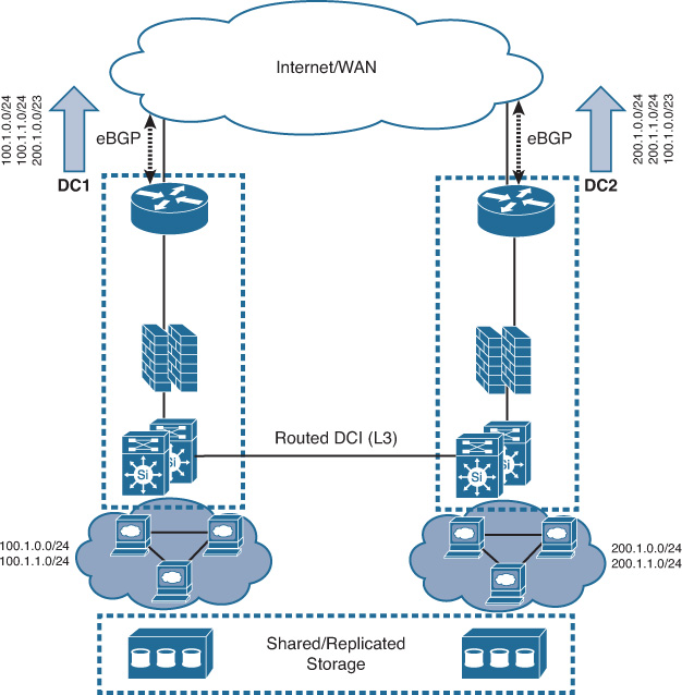
The DCI solution shown in Figure 8-20 reflects typical interconnected data centers over a routed DCI, where each site has its own IP range (either full range or a divided range). At the same time, each site advertises the other site’s IP range (such as summary of the both site’s IP range if its summarizable) for failover purposes. However, in some scenarios, the functional requirements of the interconnected DCs require each DC to provide connectivity to its local resources only in alignment with the architectures of the organization’s applications.
From the networking design point of view, this means that the DCI must not be used for failover of traffic coming from the external networks (WAN/Internet) and that the load distribution for external connections should be controlled via higher layers, such as global load balancers (also known as global site selector [GSS]). Consequently, in this design approach, each DC location will advertise only its own local IP range. This ensures that each DC will provide connectivity only to the local resources and will not provide connectivity to the other DC during some failure scenarios. Data replication between the DCs is handled by the storage design and hypothetically should ensure that both data centers can have valid and updated replicas of the data that aligns with the BC goals by achieving the desired level of RTO and RPO. This example demonstrates how the entire typical routed DCI design can change based on business, functional, or application requirements. Another example is that some data center operators advertise the same IP ranges from multiple data centers to offer an “anycast” style of load distribution; traffic will usually always prefer the closest data center in scenarios where multiple data centers exist across different geographic areas and advertise the exact same IP subnets.
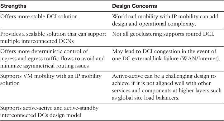
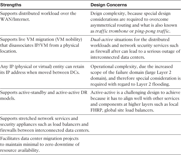
As with any design solution, network designers must understand the different aspects of the routed DCI design to be able to identify when and why to position it as a reliable DCI solution for a given DCN design (ideally based on the top-down approach). Table 8-6 summarizes the main strengths and design concerns of the routed DCI.
Layer 3 DCI Connectivity Options
The provisioning of a routed DCI connectivity between data centers can be achieved with different types of layers 3 transport mechanisms, including the following:
![]() MPLS L3VPN WAN
MPLS L3VPN WAN
![]() Tunneling over the Internet
Tunneling over the Internet
![]() Dedicated link such as dark fiber configured as a routed link
Dedicated link such as dark fiber configured as a routed link
![]() L3 over MPLS L2VPN (E-line, E-LAN)
L3 over MPLS L2VPN (E-line, E-LAN)
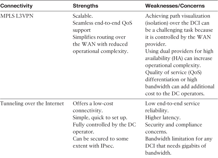
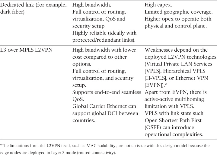
Although all these connectivity types will deliver a routed DCI, each one has its strengths and weaknesses with regard to a routed DCI solution. Table 8-7 compares the primary design aspects of each of the connectivity types listed here.
Layer 2 DCI
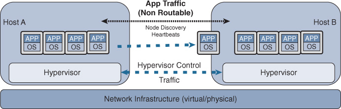
As discussed earlier, data center applications and services must always drive the design decisions of the DCI solution in terms of distance (latency), capacity, and network communication required (L2 versus L3). In today’s data centers, there are several systems, especially around the clustering of servers (geoclustering) and system virtualization, that mandate stretching Layer 2 LANs between the interconnected data centers. This stretching enables the resiliency and clustering mechanisms offered by the different applications at the web, application, and database layers to achieve specific design goals, such as application resiliency and workload allocation flexibility via workload mobility and distributed workload across multiple data centers. In today’s data centers, many system virtualization vendors require nonroutable (Layer 2) adjacency between the distributed workloads as well to achieve VM mobility, as shown in Figure 8-21.
Therefore, LAN extension between data centers became one of the most popular DCI solutions even though it is one of the most complex designs for several reasons, which are covered in this section (as are with the recommended solutions and optimization techniques later in this chapter). Table 8-8 summarizes the main strengths and design concerns of the Layer 2-based DCI.
Layer 2 DCI Connectivity Options
Today’s DCI solutions, which are capable of providing LAN extension to meet modern data center requirements, can be classified into three primary connectivity models:
![]() Dark-fiber based: Typically, this DCI model is applicable to DC operators that own the physical layer (interconnect), which offers them the freedom to enable any of the desired solutions appropriate for their requirements.
Dark-fiber based: Typically, this DCI model is applicable to DC operators that own the physical layer (interconnect), which offers them the freedom to enable any of the desired solutions appropriate for their requirements.
![]() SP controlled: This type of DCI connectivity is based on the fact the DCI (WAN/MAN) provider deploys and controls the service for the DC customers (LAN extension), such as E-Line and E-LAN services.
SP controlled: This type of DCI connectivity is based on the fact the DCI (WAN/MAN) provider deploys and controls the service for the DC customers (LAN extension), such as E-Line and E-LAN services.
![]() DC operator controlled (overlay): This type of DCI is usually based on an overlaid LAN extension solution, where the DC operator deploys and controls the emulated Layer 2 service over an IP transport such as VxLAN, OTV, and L2VPN, over GRE.
DC operator controlled (overlay): This type of DCI is usually based on an overlaid LAN extension solution, where the DC operator deploys and controls the emulated Layer 2 service over an IP transport such as VxLAN, OTV, and L2VPN, over GRE.
Note
Technically, any of the listed Layer 2 technologies and protocols can be enabled over a dark fiber; all are valid and proven solutions. However, this section focuses on enabling classic 802.1Q over a dark fiber. The other technologies, like VxLAN and OTV, are discussed as a transport agnostic where any IP transport is applicable, including dark fiber configured as routed link. An L2VPN deployed by the DC operator, however, follows the same concept with only one fundamental difference: The underlay transport must be MPLS enabled. You can either use GRE for this purpose or you can enable MPLS at the link level in case of dark fiber.
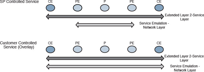
Layer 2 DCI solutions (SP controlled versus DC operator controlled) can be divided into two primary layers:
![]() The service layer is the actual extended Layer 2 services; it is almost always between the customer edges (CEs) facing the PEs.
The service layer is the actual extended Layer 2 services; it is almost always between the customer edges (CEs) facing the PEs.
![]() The network layer represents the service emulation across the IP/MPLS network (overlay), as shown in Figure 8-22. This layer varies based on who is deploying and controlling the service (SP controlled versus DC operator controlled)
The network layer represents the service emulation across the IP/MPLS network (overlay), as shown in Figure 8-22. This layer varies based on who is deploying and controlling the service (SP controlled versus DC operator controlled)
Note
The services offered by SPs are almost always L2VPN based, whereas the ones that are deployed and controlled by the DC operator (CE side) can be any DCI overlaid solution.
For the purpose of simplicity, this section covers the characteristics of these Layer 2 DCI solutions on a per-technology basis, as listed here:
![]() Dark fiber based
Dark fiber based
![]() Layer 2 over Metro Ethernet (ME) transport such as E-line and E-LAN, including the following:
Layer 2 over Metro Ethernet (ME) transport such as E-line and E-LAN, including the following:
![]() SP provisioned and controlled ME
SP provisioned and controlled ME
![]() DC operator provisioned and controlled ME over any IP transport
DC operator provisioned and controlled ME over any IP transport
![]() TRILL/FabricPath-based DCI
TRILL/FabricPath-based DCI
![]() EoMPLSoGRE (OTV) over any IP transport
EoMPLSoGRE (OTV) over any IP transport
![]() VxLAN over any IP transport
VxLAN over any IP transport
Dark Fiber-Based DCI
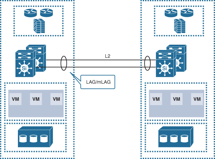
This DCI solution is based on a direct physical dark fiber link controlled by the data center operator. With this solution, the DC operator has the freedom to run any of the protocols listed earlier to establish the DCI connectivity. However, this section focuses on the usually extended LAN over 802.1Q link (dark fiber) along with mLAG, as shown in Figure 8-23. Although the following design enables data center operators to use all the mLAG member links to carry the traffic passing between the two data centers, several design optimizations must be considered, such as FHRP localization and Layer 2 flooding control (DCI path optimization, covered in greater detail later in this chapter). In addition, as covered earlier in this book, every traffic flow normally uses a single LAG/mLAG member link; this means that each traffic flow will be limited to a single member link capacity (unless the flowlet concept is used).4
4. “Dynamic Load Balancing Without Packet Reordering,” IETF draft, chen-nvo3-load-banlancing, http://www.ietf.org
Note
The dynamic load-balancing capability available today in Cisco Application Centric Infrastructure (ACI) “adjusts the traffic allocations according to congestion levels. It measures the congestion across the available paths and places the flows on the least congested paths, which results in an optimal or near optimal placement of the data, DLB can be configured to place traffic on the available uplinks using the granularity of flows or of flowlets.” [84]
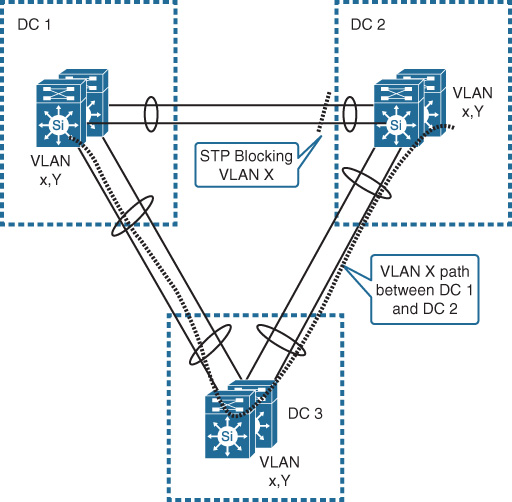
Besides the design challenges and the operational complexity that can be introduced to the DCN by the extended LAN across multiple locations, interconnecting more than two data centers over 802.1Q dark fiber links in a triangle or square topology can lead to serious design complexity and operational inefficiencies because STP is the Layer 2 control protocol in this particular design model. This means that there will be inefficient utilization of the links associated with suboptimal routing, which can be very sensitive in data center environments that require low-latency communications across the DCI. As shown in Figure 8-24, if the hosts belonging to VLAN X distributed across DC1 and DC2 need to communicate, traffic has to traverse DC3 because of STP blocking.
Although this can be fixed with STP traffic engineering (where network operators can control which link can be blocked for which VLAN from the STP point of view), this will introduce a high degree of operational complexity and limit optimal communications across to data centers only. This issue can be resolved by either considering a protocol that does not rely on STP such as TRILL, VPLS, or VxLAN (which is beyond the scope of this subsection) or by introducing the concept of core DCI to transform the design model into one that is more flexible and scalable to interconnect multiple data centers, as shown in Figure 8-25.
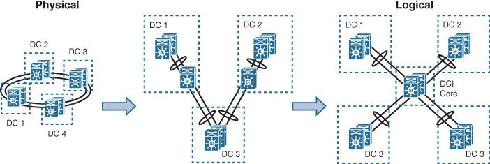
Core DCI is based on introducing two core switches deployed in switch clustering mode, ideally distributed across two different data centers to avoid introducing any single point of failure to the design. The physical connectivity of the underlying fiber, however, should be provisioned over an x wavelength-division multiplexing (xWDM) ring, where the logical point-to-point links from each DC to the core DC are created via xWDM transport lambda or wavelength over the optical ring. Ultimately, this will create a logical start topology that will eliminate STP limitations and offer a flexible and reliable DCI solution, as shown in Figure 8-25.
However, in addition to the fact that this design can be an expensive option in terms of capex and opex, not every location (geographic area) has xWDM available. Therefore, these design constraints have to be considered during the planning and design optimization stage to avoid providing impractical design recommendations. (An impractical design is one that is technically valid but practically cannot be deployed because of certain design constraints.)
Layer 2 DCI over ME Transport
This design option is primarily based on emulating a Layer 2 LAN over an IP MPLS-enabled infrastructure, as discussed earlier in this chapter. The most common connectivity models for the data center DCI solution are either the E-Line or E-LAN connectivity models.
This DCI connectivity design option can be provisioned either by the SP or by the DC operator, as described here:
![]() SP controlled: In this scenario, the SP owns the MPLS infrastructure and emulates the Layer 2 transport transparently to the DC side for the DCI (E-line, E-LAN).
SP controlled: In this scenario, the SP owns the MPLS infrastructure and emulates the Layer 2 transport transparently to the DC side for the DCI (E-line, E-LAN).
![]() DC operator controlled: In this scenario, the DC operators (enterprise or SP DC) design and set up their own overlaid ME solution, such as E-Line or E-LAN, over any IP transport with the aid of a tunneling mechanism to enable MPLS for the pseudo wires (PWs) of the emulated LAN, such as VPLS-over-GRE-over-IP. Similarly, if the DC operator has a dark fiber-based DCI MPLS, it can be enabled across this DCI. Run either Ethernet over MPLS (EoMPLS) or VPLS based on the physical layout.
DC operator controlled: In this scenario, the DC operators (enterprise or SP DC) design and set up their own overlaid ME solution, such as E-Line or E-LAN, over any IP transport with the aid of a tunneling mechanism to enable MPLS for the pseudo wires (PWs) of the emulated LAN, such as VPLS-over-GRE-over-IP. Similarly, if the DC operator has a dark fiber-based DCI MPLS, it can be enabled across this DCI. Run either Ethernet over MPLS (EoMPLS) or VPLS based on the physical layout.
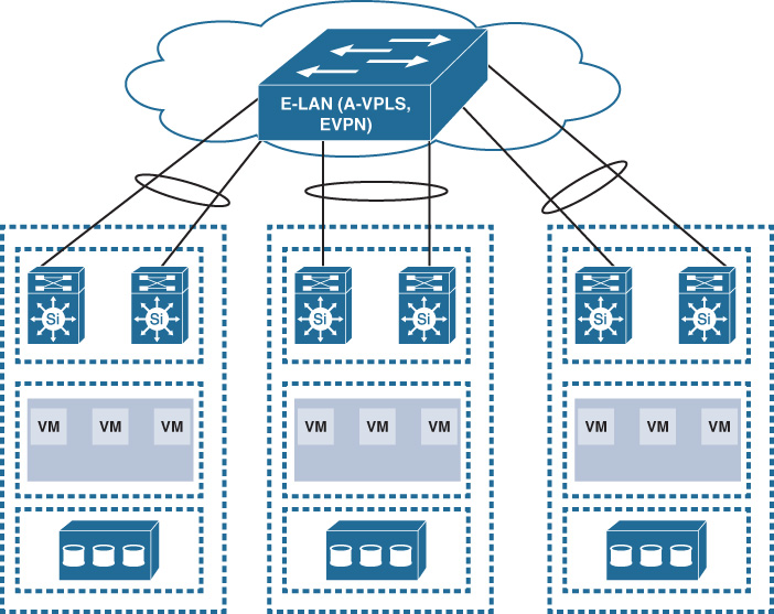
Furthermore, as discussed earlier in Chapter 6, “Service Provider MPLS VPN Services Design,” EVPN and Advanced VPLS (A-VPLS) can provide DCI capabilities similar to dark fiber with mLAG but on a larger scale over an emulated L2 LAN and with a cheaper price, as shown in Figure 8-26. In addition, EVPN with PBB can meet very large-scale public cloud-grade DCI requirements (scales to millions of MACs) with a simplified and optimized control plane (BGP based) combined with the PBB MAC hiding principle.
TRILL-FabricPath-Based DCI
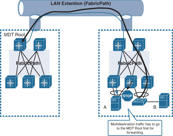
As discussed earlier, the MDT in FabricPath (FP) controls the forwarding of multidestination traffic. Normally, a root for each MDT is assigned per FP topology in a multitopology environment. From the perspective of design performance and efficiency within a single LAN/DCN environment, this is not a concern because the traffic is still within the boundary of the same high-speed LAN/DCN.
In contrast, when FP is extended over the DCI, this behavior can impact the entire DCI solution simply because the multidestination traffic (BUM traffic) will traverse the DCI link all the way to the MDT root that might be residing at the remote DC. This will result in high utilization (most probably congestion) to the DCI link, especially if there are applications using multicast. In other words, the placement of the MDT root with FabricPath enabled over DCI is critical. The scenario in Figure 8-27 shows how multidestination traffic from host B’s access switch (for example, multicast or unknown unicast) is sent back to DC1 to the MDT root then back to DC2, even though both host A and host B are located within the same physical data center.
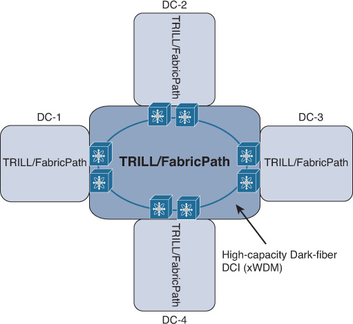
However, TRILL/FP can be considered a valid and feasible DCI solution in scenarios where the distance between the interconnected DCs is short, with connectivity over high-capacity links, such as 10/40/100-Gbps interconnections (ideally overprovisioned). In this case, traffic trombone may not be an issue, and TRILL/FabricPath can offer a scalable design of multiple interconnected data centers in terms of number of sites and MAC address table scaling, along with failure domain containment, as shown in Figure 8-28.
Overlay Transport Virtualization
Overlay Transport Virtualization (OTV) is an IP-based functionality designed by Cisco Systems specifically to offer simplified and scalable Layer 2 extension capabilities over any transport infrastructure, such as Layer 2, Layer 3, or label switched. OTV introduced the concept of MAC routing, where IS-IS, as a control plane protocol, exchanges MAC reachability information between OTV edge nodes, providing seamless LAN extension functionality. Furthermore, OTV provides a native built-in multihoming capability, increasing the HA of the overall solution.
As a result, OTV provides the capability to extend Layer 2 segments over multiple DCI edges of multiple data centers without introducing any loop or unicast flooding that can impact the effectiveness of the DCI solution and the overall stability of the interconnected data centers. Concurrently, STP is kept contained within each data center domain, as shown in Figure 8-29. Therefore, using OTV (when applicable and the choice is available) over any transport, including dark fiber, to provide LAN extension can simplify and improve designing, implementing, and maintaining the DCI solution, especially when multiple data centers need to be interconnected.
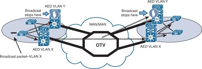
OTV selects an authoritative edge device (AED) for each group of the extended VLANs to control the MAC address advertisement for these VLANs and the ingress and egress traffic forwarding for these VLANs per site. As shown in Figure 8-29, only the AED of VLAN X will forward broadcast traffic sourced from the local site across the OTV DCI. Similarly, only the AED of VLAN X at the remote site will forward the broadcast traffic internal to VLAN. This capability offers an optimized behavior for an extended LAN over a DCI (mitigate the impact of broadcast storms across the DCI).
There are some scenarios involving large data centers with several PODs interconnected over Layer 3 links (such as Layer 3-based Clos fabric) per DC. In these types of scenarios, if the DC operator needs to extend Layer 2 VLANs across multiple PODs within the same DC and across multiple DCs in different regions, an overlay solution is required to achieve this, as shown in Figure 8-30. With the typical flat OTV design, this can be a challenging design, especially if many DC sites need to be interconnected. The OTV has limits in terms of maximum supported sites to be interconnected; this number varies based on the platform/software release.
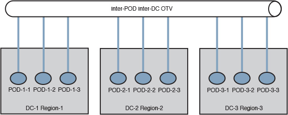
By introducing the multitier OTV design approach, network designers can accommodate the requirements of extending Layer 2 within each DC (across the different PODs) and at a global level (across different data centers in different regions) [60]. This design can overcome scaling limitations with regard to the supported number of interconnected sites with OTV and achieve a more structured Layer 2 extension, where VLANs can be extended selectively between the different tiers/regions, as shown in Figure 8-31. In spite of these advantages, this design approach requires careful path optimization considerations, which may lead to increased design and operational complexity. (The more data centers to be interconnected, the more complex to design and manage.)
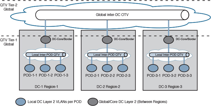
VxLAN-Based DCI
The IETF standard VxLAN was created and commonly used as a data center fabric overlay protocol to facilitate and optimize modern data center performance and agility in response to virtualized and cloud-based data center requirements. In VxLAN, VMs can be moved anywhere within the DC, because of abstraction between the location of the VM/application within the DC and the physical access/leaf switch and port VM mobility. VxLAN adds simplicity, transparency to applications, and flexibility to modern Clos fabric architectures; in addition, it enhances its ability to scale an extremely large number of VMs/MACs, especially when an MP-BGP EVPN control plane is used for VxLAN.
BGP as a control plane, together with VxLAN headend replication, can optimize VxLAN behavior with regard to multidestination traffic for MAC learning (broadcast and unknown unicast), especially as the behavior has become like Layer 3 routing (MAC learning is based on MAC address advertisement). Flooding will be eliminated unless there is a host that has not advertised or learned MAC, and only in this case will the typical Layer 2 flooding be used. At the time of this writing, VxLAN began to be considered a DCI solution, especially the unicast mode of VxLAN, because it can be more controllable at the DCI edge (can be policed more deterministically than multicast mode). This is applicable to any of the VxLAN design models (host based or network based), as shown in Figure 8-32.
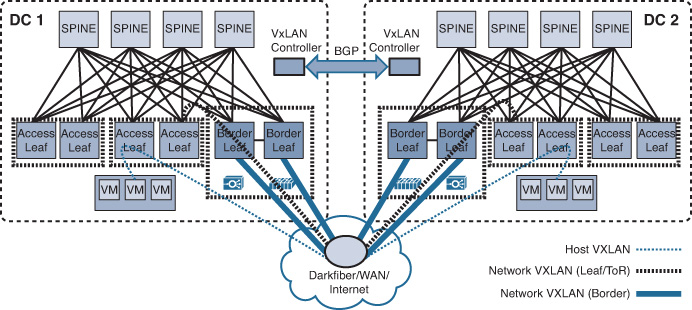
Note
The placement of the functionality of a VxLAN controller with BGP (EVPN) as a control plane (where all the hosts’ MAC addresses are hosted and updated) can vary from vendor to vendor and from solution to solution. For example, it can be placed at the spine nodes of the Clos architecture, as well as cloud be placed at the virtualized (software-based) controller, such as the Cisco nexus 1000v virtual supervisor module VSM. It also can be used as a route reflector to exchange VTEP list between multiple VSMs.
Note
Technically, you can use all the VxLAN models discussed earlier (host and network based) at the same time. However, from a design point of view, this can add design complexity and increase operational complexity. Therefore, it is always recommended to keep it simple and start with one model that can achieve the desired goal.
Currently, one of the challenges of using VxLAN as a DCI solution is the behavior of the distributed controller across the two DCs following a DCI failure event (split-brain) and after DCI link recovery. In addition, considerations about the VxLAN gateway location (localized versus at a remote location) can impact the design. However, at the time of this writing, advancements in VxLAN are increasing rapidly. Therefore, it is quite possible that new features and capabilities will be available in the near future to make VxLAN a more robust DCI solution.
Note
The scope of each DC VxLAN can be contained within each DC locally, while the terminated VxLAN VTEPs at the DC/SP border nodes can be extended across the SP network that has EVPN enabled. Each VxLAN VNI is mapped to a unique EVPN instance (VNI-to-EVI 1:1 mapping) to maintain end-to-end path separation per VxLAN. This design offers a scalable, integrated DCI solution that takes advantage of both solutions in scenarios where EVPN is already in place as a DCI and the DC operator is deploying VxLAN within each DC,5 as shown in Figure 8-33.
5. IETF draft, boutros-l2vpn-vxlan-evpn-xx, http://www.ietf.org.
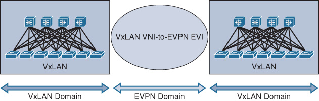
Each of the preceding DCI solutions has different characteristics and strengths and weaknesses. Table 8-9 compares the DCI solutions from different design aspects.
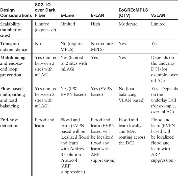
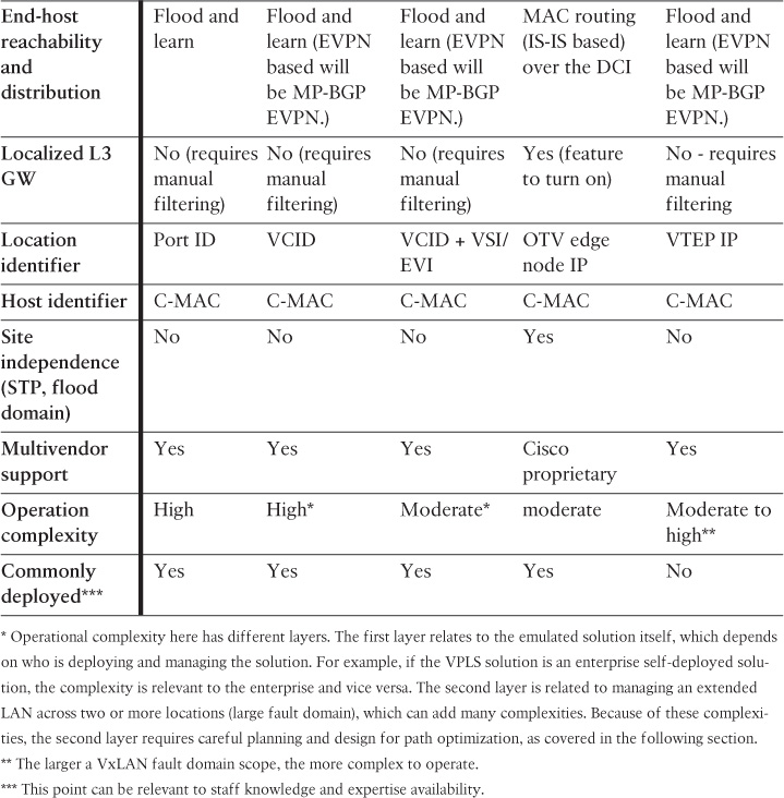
DCI Design Considerations
The complexity of designing data center interconnect solutions does not only pertain to the selection of the right DCI connectivity option (for example, Layer 2 or Layer 3). Several other components and considerations must be taken into account to achieve an optimal and reliable design. It is obvious from the design options discussed in the previous section that Layer 2 DCI has a wider range of connectivity options. At the same time, its design is the most challenging one. Therefore, it requires a careful and structured planning and design approach.
To achieve an optimal DCI design that is business driven and supports current and future requirements, network architects and designers must have a good understanding of the business goals and drivers with regard to BC. This is to be followed by a good understanding of the applications and services within the data center and its architecture in terms of communications and network requirements (for example, multitier applications, data replication in use, and bandwidth and latency requirements).
For instance, if you are designing a data center that hosts public services, such as Internet banking services and applications, traffic spikes can increase rapidly because of an extremely large number of sessions, which are unpredictable to some extent. In contrast, designing a data center to host HR applications for a large-scale organization is more predictable in terms of the number of sessions. This relates to the expected design scale and bandwidth requirements to understand what these applications require (bandwidth, latency) and how they will behave during and after any DC failure scenario. In other words, the top-down design approach must be followed during the planning and design stages to achieve a successful DCI solution, as summarized in Figure 8-34.
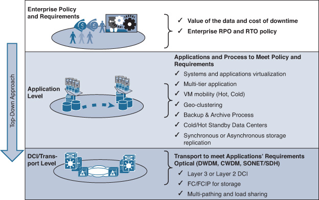
The previous section focused more on DCI connectivity options and their characteristics (the focus was individually per DCI option). This section, however, focuses on the important design aspects of a DCI as a solution by highlighting the limitations and challenges and the recommended solutions that you can use to optimize the design. In general, an ideal data center interconnect design must consider the design aspects in Table 8-10 to achieve a scalable, stable, reliable, and flexible business-driven DCI solution.
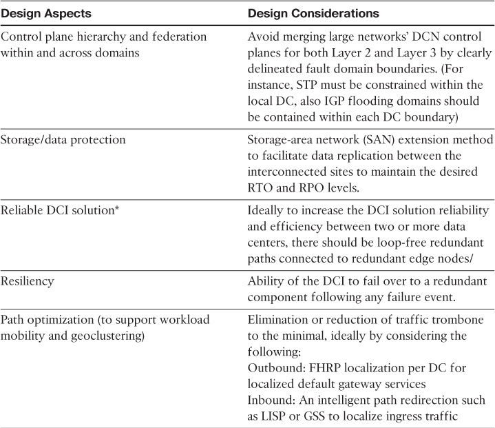
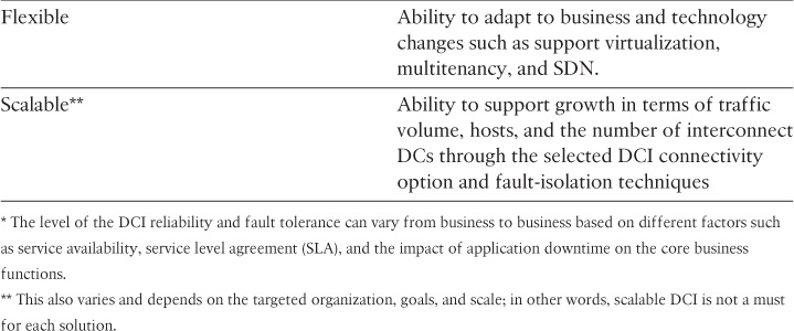
This section covers the following design considerations with regard to DCI solution design:
![]() SAN extension
SAN extension
![]() Path optimization techniques with DCI
Path optimization techniques with DCI
![]() Network and Security Services Placement
Network and Security Services Placement
SAN Extension
The protection of the data via replication, caching, or backup is foundational to achieving the desired level of DR, BC, and business resilience (BR), and must take into account the RTO and PRO levels required by the business. Figure 8-35 describes the relationship between DR, BC, BR and the level of data protection.
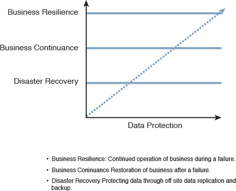
Consequently, understanding the required or in-use data protection mechanism (for example, replication, caching) and how the application uses the storage is key to planning and designing a DCI solution. For example, some virtualization solutions are designed in a way that when a VM moves from one data center to another, the VM will continue use the storage located at the source/home data center.
In addition, moving application members across data center locations should not break the application. For instance, applications residing on top of the moved VMs need storage access (for example, database), as shown in Figure 8-36. Therefore, the storage design and replication can significantly impact the performance of the DCI. The dashed line in Figure 8-36 illustrates the scenario in which a moved VM continues to access data via the remote storage over the DCI link. The (nondotted) line shows the optimized solution in which the moved VM uses local storage when possible.
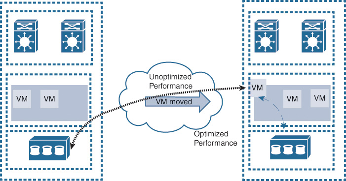
Understanding this behavior can impact the DCI connectivity option selection in terms of distance (latency) and capacity.
Synchronous Versus Asynchronous Data Replication
Synchronous and asynchronous are the primary methods of data replications used in a majority of today’s data centers; each has its own characteristic and influence to the overall DCI design:
![]() Synchronous data replication: With this method, an application receives the acknowledgment of I/O completion when both the main and secondary sites are updated. This method offers almost zero data loss and very fast recovery time from failures that can occur at the main site. Appropriately, it is also known as the zero data loss replication method (zero RPO). A potential downside of this method is cost, because it can be an expensive choice with distance limitations because of its high-bandwidth and low-latency requirements.
Synchronous data replication: With this method, an application receives the acknowledgment of I/O completion when both the main and secondary sites are updated. This method offers almost zero data loss and very fast recovery time from failures that can occur at the main site. Appropriately, it is also known as the zero data loss replication method (zero RPO). A potential downside of this method is cost, because it can be an expensive choice with distance limitations because of its high-bandwidth and low-latency requirements.
![]() Asynchronous data replication: Based on this method, an application receives the acknowledgment of I/O completion once the main disk is updated, while the copy continues to the remote disk array. Because the data is replicated to the remote array after the I/O is acknowledged as completed to the host, the remote disk array can be located anywhere, virtually or physically, at any distance. However, this method has a higher risk of data loss if the DC goes down before the data is completely replicated.
Asynchronous data replication: Based on this method, an application receives the acknowledgment of I/O completion once the main disk is updated, while the copy continues to the remote disk array. Because the data is replicated to the remote array after the I/O is acknowledged as completed to the host, the remote disk array can be located anywhere, virtually or physically, at any distance. However, this method has a higher risk of data loss if the DC goes down before the data is completely replicated.
Furthermore, the distance between the interconnected data centers can influence to a large extent the selection of the data replication method that you can use on the disk arrays of the connected data centers, because the distance almost always impacts the response time (latency), which in turn will impact the maximum I/O per second (IOPS) performance across the interconnected data centers. However, if the application is designed to tolerate some IOPS, the distance impact may be reduced.
From the network and DCI design point of view, regardless of which method applications are operating with (synchronous or asynchronous), the design must identify the used method or methods [41,72]. Concurrently, it must take into account how the methods can impact the DCI design, especially with regard to factors such as bandwidth, latency, and distance. These factors must all collectively act as a solution to meet the DR and BC goals, from a business point of view.
Figure 8-37 summarizes the most common SAN extension options.
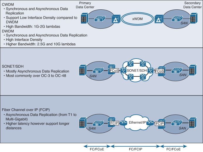
Note
The highlighted data replication methods and each SAN extension option in Figure 8-37 are based on very generic link or application characteristics. However, these are not absolute, because as discussed earlier in this section, it can change based on various factors such as distance, latency, bandwidth, application attributes, and so on.
DCI Path Optimization Techniques
As covered earlier in this chapter, designing a DCI solution is one of the most challenging design tasks. For instance, selecting a DCI connectivity option, such as E-LAN, does not mean the network engineers can deploy it and everything will work fine to achieve the desired goals. In fact, selecting the DCI connectivity option is only the foundation of the DCI solution design. In other words, network designers should consider the behavior of the other components in the higher layers of the data center (storage, workload, applications, security services) when this DCI is enabled and when workload is moved from one location to another.
Throughout this process, several other considerations must be kept in mind. These include the targeted design goal of the DC (such as active-active versus active-standby) and the method through which external users should access the data center resources (ingress and egress traffic flow considerations). Therefore, the network designer needs to perform what is commonly known as DCI path optimization.
This section covers the different design considerations and techniques that must be taken into account when designing a DCI solution to optimize the traffic flow. In general, the traffic flow of DCNs can be categorized into three main categories:
![]() User to host: This traffic flow usually refers to ingress traffic sourced from external or internal users to the local data center resources. The entry point of this traffic flow is normally controlled by the routes advertised by the DC network edge node.
User to host: This traffic flow usually refers to ingress traffic sourced from external or internal users to the local data center resources. The entry point of this traffic flow is normally controlled by the routes advertised by the DC network edge node.
![]() Host to user: This traffic flow represents the return traffic or sessions from the server to the external users. The first exit point is controlled by the server’s Layer 3 gateways, usually the FHRP VIP.
Host to user: This traffic flow represents the return traffic or sessions from the server to the external users. The first exit point is controlled by the server’s Layer 3 gateways, usually the FHRP VIP.
![]() Host to host: This traffic flow represents the traffic flowing between hosts within the same physical DC or between interconnected DCs over a DCI link, such as a multitier application. (With workload mobility, this is also known as east-west traffic flow.)
Host to host: This traffic flow represents the traffic flowing between hosts within the same physical DC or between interconnected DCs over a DCI link, such as a multitier application. (With workload mobility, this is also known as east-west traffic flow.)
In data center types of networks, packets often have to traverse multiple network services and security nodes in both ingress and egress directions (depending on the detailed design) before any given packet reaches its targeted destination (whether an internal host or an external user). These nodes are most commonly load balancers, firewalls, web application firewalls, intrusion prevention/detection systems (IPS/IDS), and DC edge routers. If you fail to take these nodes along the path into consideration, the entire data center design can be broken.
To a large extent, a good understanding and analysis of the three primary traffic flow types mentioned earlier can enhance the design by optimizing the path any traffic flow should take to avoid overloading the DCI link and breaking some application requirements. For example, asymmetrical routing can either lead to black-holing the traffic because of some security nodes in the path, or it may increase its latency. The subsequent sections discuss some of the impacts and possible solutions of these different traffic flows with regard to DCI path optimizations.
Understanding Multitiered Application Architecture
A thorough understanding of how multitiered applications and services within a data center work and communicate is vital for network designers during the planning of positioning or optimizing of a DCI solution. This is because with system virtualization and workload mobility, the physical host and IP localization is not associated anymore with a fixed physical location (data center).
For instance, several business applications, such as customer relationship management (CRM) and enterprise resource planning (ERP), consist of multiple elements interconnected in a sophisticated manner that construct the overall service or application. In addition, some of these elements may need to have a level of protection. For example, a web server might need to be placed behind a web application firewall, and the database behind a network firewall. As result, what is seen as a cohesive service or application is, in fact, a combination of multiple services and applications that communicate in the back end to provide the unified interface to the end user.
So to reiterate, a thorough understanding of how these services and applications communicate between each other can help the network designer make better decisions and provide a better DCI solution. What is meant by decisions here is not only related to the DCI connectivity type and routing design. It also refers to when an alignment needs to be done with other teams, such as server and application teams. With certain applications (multitiered), it is better to migrate them together rather than move only one element of the multitiered application. For example, in Figure 8-38, a web server (VM) that is part of a multitiered application consisting of a web server, application server, and database server was moved to the secondary DC.
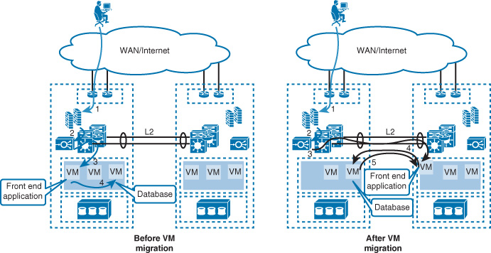
As shown in Figure 8-38 (the scenario on the left), before the front-end application is moved, VM traffic is routed and switched within the same physical DC (the traffic flow between different network and security components, also known as ping-pong traffic). In the scenario on the left, the effect of the ping-pong traffic has no impact on the latency because it is contained with the same DC. However, after moving the front-end VM traffic between the two data centers over the DCI, it can be increased. The ping-pong traffic, in this situation, can significantly impact the latency and efficiency of the DCI link. For example, traffic between each application tier will have to return to the primary DC where the active Layer 3 gateway and firewall are located. If additional network services are integrated between the different application tiers (which is the case in most of the deployments) such as load balancer, Secure Sockets Layer (SSL) offload, or web application firewall enabled, there might be about ten round trips (ping-pong traffic) for a simple web/DB query crossing the DCI. Consequently, by understanding how the multitiered application works, and to avoid the impact of this critical issue, it may be more feasible to move the entire multitiered application rather than only a single VM or application.
Optimize Routed DCI with Stateful Security Services
As discussed in Chapter 4, this design must consider a direct interconnection between the edge routers connected to the external connections (physical or tunneled interface) to avoid any traffic black-holing in the event of WAN/Internet link failure of the active DC by the stateful nodes in the path such as the firewalls (usually each DC maintains its own independent pair of firewalls), which potentially leads to resetting the existing active sessions. This solution assumes that the time for the failover process to complete is less than the timeout duration of the active sessions. For a more detailed analysis, along with design considerations, see Chapter 4, the section titled “Asymmetrical Routing with Multihoming (Issue and Solution).”
Egress Traffic Flow Optimization Using FHRP Localization
One of the primary path optimization principles with regard to an extended LAN over a DCI is the localization of the Layer 3 gateway services (FHRP) of the outbound traffic flow by the moved workload between the different data center locations. With LAN extension, FHRP such as Hot Standby Routing Protocol (HSRP) will usually be active on the primary DC only, which will result in suboptimal (nonlocalized) egress traffic flow. This might be acceptable in some scenarios where the interconnected DCs are located in the same building or campus and interconnected over high speed links, such as 10G or 40G dark fiber links. However, for large DCs with a high workload and interconnected over a private MAN, WAN, or over an SP-provisioned DCI, this can be unacceptable behavior. One simple and common solution is to use a VLAN access control list (VACL) or port ACL (PACL) to filter out FHRP over the DCI to maintain an active FHRP node per DC to process egress traffic flows locally, as shown in Figure 8-39.
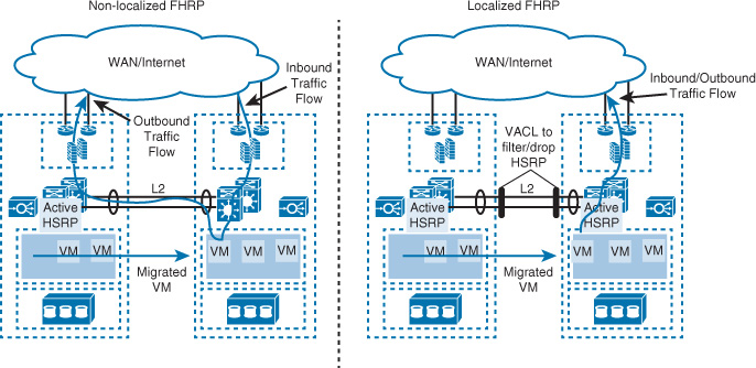
Ingress Traffic Flow Optimization
Optimizing egress traffic flow is only half the job in achieving acceptable and reliable path optimization for interconnected data centers. This section covers the most common techniques that you can use to optimize (localize) ingress traffic flow when the resources are moved or migrated between data center locations across a Layer 2 or Layer 3 DCI. Furthermore, these techniques can help achieve an active-active data center DR model:
![]() Domain Name System (DSN) based
Domain Name System (DSN) based
![]() Route injection
Route injection
![]() IP mobility (for example, LISP)
IP mobility (for example, LISP)
Figure 8-40 summarizes how ingress traffic flow optimization with interconnected DCs can decouple IP from its physical location.
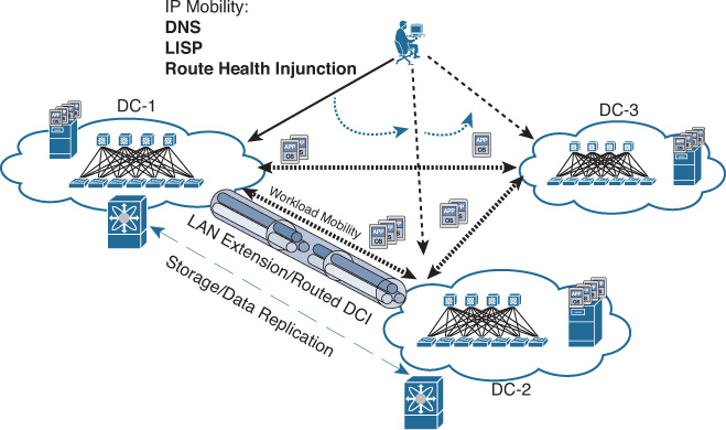
DNS Based
This design approach is one of the most common and proven approaches (but most common does not always mean the best). This solution relies on DNS (name to IP) redirection, most commonly deployed by using a global load balancer that acts as a DNS forwarder to resolve DNS queries to local (site-specific) load balancers per DC.
Normally, the global load balancer (also known as the global site selector [GSS]) performs keepalive checking with each DC load balancer while the local load balancers probe the real local servers. Hence, the global load balancer can populate the DNS entries with the appropriate IPs based on the keepalive response. In fact, the GSS can consider various criteria, such as response time and percentage of network utilization, in addition to weighting capabilities that can distribute traffic across different sites (active-active).
Therefore, this approach can achieve intelligent ingress traffic control and distribution across multiple DC locations facilitated by the GSS for the new ingress sessions. Existing sessions, however, cannot be redirected (even if the VM was moved) as long as the session is active, as shown in Figure 8-41. Although this behavior is most common with regard to GSS, load-balancing vendors may introduce new capabilities to overcome this limitation. Therefore, detailed traffic handling can vary while the overall design concept stays the same.
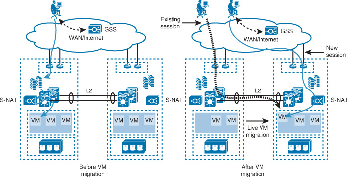
Although DNS-based ingress traffic control is an easy and reliable solution, this design has the following limitations:
![]() Supports traffic/session that use DNS (name) only.
Supports traffic/session that use DNS (name) only.
![]() Proxy cache of DNS entries can lead to traffic black holing until it is refreshed with a new DNS entry.
Proxy cache of DNS entries can lead to traffic black holing until it is refreshed with a new DNS entry.
Note
The GSS concept described here is a generic concept that is available by leading load-balancing vendors.
With the DNS-based solution, Layer 2 extension over the DCI is not a prerequisite (unless it required by the applications or the distributed workloads). In addition, if a routed DCI in each DCI can maintain its own IP rang, this in turn will simplify the design by avoiding the egress traffic flow optimization considerations and other challenges related to the extended Layer 2 over DCI.
Route Health Injection
The route health injection (RHI) approach is also facilitated by load balancing (LB) nodes located across the interconnected data centers. With this approach, LBs are used in each DC to probe the local subnet/VLAN per host for an availability check with probe filtering over the DCI, as shown in Figure 8-42.
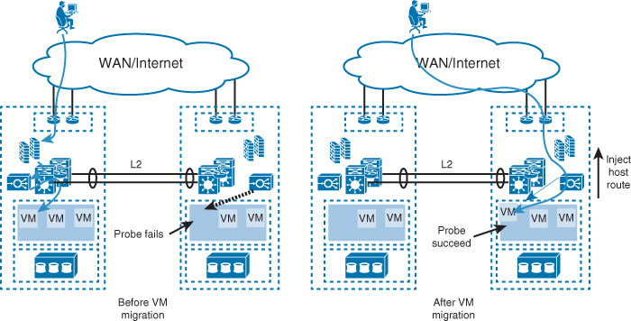
The scenario on the left in Figure 8-42 illustrates the DCs in a normal situation, in which the VM/server is located in the primary DC (DC-1) and the load balancer in DC-2 is monitoring the VM/host IP. At this stage, the probe should fail because the IP of the intended host is not located at the secondary DC. Once the VM has migrated to the secondary DC, the probe will succeed. This will trigger the load balancer to inject the host IP to the upstream edge routers (/32), which will redirect ingress traffic destined for this IP at the secondary DC (longest match principle).
Locator/ID Separation Protocol
LISP is developed to work in multihoming environments and facilitate communication in the IP mobility scenario in between LISP and non-LISP sites by separating IP addresses into two new numbering spaces: endpoint identifiers (EIDs) and routing locators (RLOCs), along with a dynamic endpoint tunneling encapsulation. Figure 8-43 summarizes the LISP architectural components.
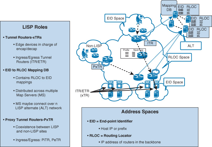
Note
Each DC edge node in Figure 8-43 of the LISP sites ideally should have both xTR roles (ITR and ETR) to correctly process both inbound and outbound traffic flows with regard to IP mobility to the internal EIDs. However, remote branches usually have only end users needing to access DC resources. Therefore, it is possible for the LISP edge nodes of the remote sites (benches) for only the ITR role to be deployed, in which return traffic or any traffic sourced from the DC LISP site will reach remote site subnets using the typical native routing. The LISP Mapping DB server role can also be deployed internally within the DC either by using dedicated nodes (in large-scale DC environments) or to be co-located at the DC aggregation nodes in smaller scale ones.
As an IP mobility routing mechanism, LISP offers data center operators the flexibility to either enable the transport over Layer 2 or routed DCI. In both scenarios, moved or migrated workloads (VMs) can maintain their original IP address. However, for LISP to deliver its promised value, remote sites must be LISP enabled, as much the nodes mapping between the non-LISP and LISP domain (PxTR), as shown in Figure 8-43.
Furthermore, although LISP offers data center operators the flexibility to use either the Layer 2 or routed DCI connectivity model between the different data centers, they do not operate exactly in the same manner with regard to workload mobility. That is why when migrating or moving VMs over routed DCI it is recommended (at the time of this writing) to target cold VM migration and not live migration. This avoids some ARP issues that can break the communications between the moved workload and other nodes (end users or hosts) after the migration. In addition, LISP supports multitenant environments that require path separation between networks within LISP sites and between non-LISP sites, as shown in Figure 8-44.
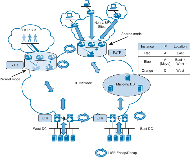
As shown in Figure 8-44, there are two modes in which the xTRs can be deployed with regard to LISP and network virtualization. With the shared mode, usually there will be a shared (single) IP range of the RLOC nodes in the backbones (multiple VRFs/EIDs mapping to a single RLOC). In contrast, the parallel mode offers the ability to maintain a separate IP range (may be separate virtual or physical nodes or interfaces) of the RLOC IPs (multiple RLOC VRFs can run in parallel).
Table 8-11 compares the design options discussed in this section with regard to IP mobility over interconnected data centers.
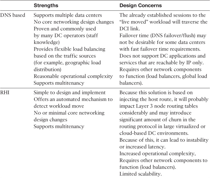
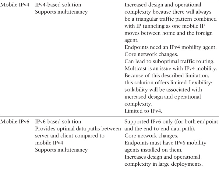
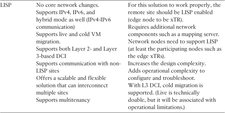
Network and Security Services Placement
The main concern with these devices in the data center traffic flow is that these devices normally operate in a stateful manner by maintaining information about the state of each specific traffic flow that passes through them. Therefore, to achieve smooth integration between data centers over a DCI without adding additional complexity, it is recommended to avoid stretching network service and security devices such as load balancers and firewalls, for the following reasons:
![]() Redundancy is usually controlled by two devices, whether they operate in active-standby or active-active modes. Stretching these devices across two different locations limits the maximum number of data centers to two.
Redundancy is usually controlled by two devices, whether they operate in active-standby or active-active modes. Stretching these devices across two different locations limits the maximum number of data centers to two.
![]() Maintaining a reliable connectivity for the failover link between the redundant devices (the physical interconnect between devices used for health check and session state synchronization) is difficult because of its sensitivity to latency. Any failure in this link can lead to a split-brain situation, which can bring both data centers down.
Maintaining a reliable connectivity for the failover link between the redundant devices (the physical interconnect between devices used for health check and session state synchronization) is difficult because of its sensitivity to latency. Any failure in this link can lead to a split-brain situation, which can bring both data centers down.
![]() Stretching the redundant devices can increase traffic trombone over the DCI.
Stretching the redundant devices can increase traffic trombone over the DCI.
![]() In addition, when considering LISP to steer flows between data center locations, special attention needs to be paid to the following concerns:
In addition, when considering LISP to steer flows between data center locations, special attention needs to be paid to the following concerns:
![]() Because the LISP xTR nodes performs the User Datagram Protocol (UDP) encapsulation for the original IP packets, firewalls must be deployed south to the LISP xTR nodes to permit the application of security policies on the original IP packets.
Because the LISP xTR nodes performs the User Datagram Protocol (UDP) encapsulation for the original IP packets, firewalls must be deployed south to the LISP xTR nodes to permit the application of security policies on the original IP packets.
![]() If a firewall needs to be placed between the host default gateway and the xTR, LISP multihop host mobility functionality is required.
If a firewall needs to be placed between the host default gateway and the xTR, LISP multihop host mobility functionality is required.
Summary
It is obvious that data center design combined with data center interconnect is one of the most challenging network design tasks. It requires the involvement of several teams and has to consider the different components collectively forming a data center environment. This chapter also covered how the workload and applications of today’s data centers are driving the change of modern DCN architectures. In addition, various approaches to designing modern data centers were discussed and compared, with regard to the underlay and overlay protocols. Furthermore, this chapter stressed the importance of BC and DR models on the overall DCI design, while considering the different application requirements and how they can influence design decisions about DCI connectivity and traffic path optimization.
Further Reading
“Software-Defined Networking: A Perspective from Within a Service Provider Environment,” https://tools.ietf.org/html/rfc7149
“VxLAN DCI Using EVPN,” http://tools.ietf.org/id/draft-boutros-l2vpn-vxlan-evpn-04.txt
IETF draft, “Extending TRILL over WAN,” https://tools.ietf.org/html/draft-xl-trill-over-wan-01
“VMDC 3.0.1 Design Guide,” http://www.cisco.com/c/en/us/td/docs/solutions/Enterprise/Data_Center/VMDC/3-0-1/DG/VMDC_3-0-1_DG.html
“Data Center Access Layer Design,” http://www.cisco.com/c/en/us/td/docs/solutions/Enterprise/Data_Center/DC_Infra2_5/DCInfra_6.html
“Cisco Application Policy Infrastructure Controller Data Center Policy Model,” http://www.cisco.com/c/en/us/solutions/collateral/data-center-virtualization/application-centric-infrastructure/white-paper-c11-731310.html
“Routing Bridges (RBridges): Base Protocol Specification,” https://tools.ietf.org/html/rfc6325
“IS-IS Extensions Supporting IEEE 802.1aq Shortest Path Bridging,” https://tools.ietf.org/html/rfc6329
IETF draft, “An Architecture for Overlay Networks,” draft-ietf-nvo3-arch-03, http://www.ietf.org