
Chapter 4. Enterprise Edge Architecture Design
Enterprise edge refers to the various enterprise network modules and components that facilitate efficient and secure communication between the different enterprise locations, including campuses, data centers, third-party external connections, remote sites, business partners, mobile users, and the Internet. Typically, enterprise edge can be divided into two primary modules as part of the modular enterprise architecture:
![]() WAN module
WAN module
![]() Internet module
Internet module
This chapter covers different design options and considerations for the WAN and Internet modules.
Note
The WAN and Internet enterprise modules may vary from design to design in terms of naming, size, and functionality. For instance, some designers combine the functions of these two modules into one module. In spite of this, the overall design principles and goals are similar to a large extent.
Enterprise WAN Module
The WAN module is the gateway of the enterprise network to the other remote sites (typical remote branches) and regional sites. As part of the modular enterprise network architecture, this module aggregates and houses all the WAN or MAN edge devices that extend the enterprise network to the remote sites using different transport media types and technologies. Enterprises require a WAN design that offers a common resource access experience to the remote sites, along with sufficient performance and reliability.
As organizations move into multinational or global business markets, they require a flexible network design that reduces the time needed to add new remote sites. They also require the deployment of new technologies that support emerging business applications and communications. In addition, it is becoming a common business requirement for users to have a consistent experience when connecting to the enterprise’s online resources (such as applications and files), whether they are at the company headquarters or at a remote site; therefore, the WAN design should be flexible enough to accommodate different business application requirements. It should also offer the ability to scale bandwidth or to add new sites or resilient links without any major change to the overall design architecture.
From an enterprise architectural point of view, the primary WAN module can be either coresident physically within the data center block of the enterprise or at the primary enterprise campus. In both cases, there is “no difference” for the WAN module architecture itself, because the aggregation layer of the WAN module will be connected to the core layer of either the enterprise campus or data center.
This chapter covers and compares the different design options that you can use to provide the most suitable WAN design to meet various business, functional, and technical requirements.
WAN Transports: Overview
One of the primary concerns of enterprise IT leaders is to manage costs and maintain reliable WAN infrastructures to meet their business goals. Furthermore, businesses are realizing that avoiding the complexities around the WAN transport between the different enterprise locations is becoming key to success in today’s high-tech competitive market where technology solutions became the primary business enabler and facilitator. Most commonly, enterprise IT leaders are always concerned about adopting a WAN solution that is capable and agile enough to address the following considerations:
![]() Interconnect the different enterprise locations and remote sites that are geographically dispersed
Interconnect the different enterprise locations and remote sites that are geographically dispersed
![]() Meet enterprise security policy requirements by protecting enterprise traffic over the WAN (secure transport), to offer the desired end-to-end level of protection and privacy across the enterprise network
Meet enterprise security policy requirements by protecting enterprise traffic over the WAN (secure transport), to offer the desired end-to-end level of protection and privacy across the enterprise network
![]() Cost-effective and reliable WAN by providing flexible and reliable transport that meets the primary business objectives and critical enterprise application requirements and that supports the convergence of voice, data, and video to satisfy the minimum requirements of today’s converged enterprise networks
Cost-effective and reliable WAN by providing flexible and reliable transport that meets the primary business objectives and critical enterprise application requirements and that supports the convergence of voice, data, and video to satisfy the minimum requirements of today’s converged enterprise networks
![]() Support business evolution, change, and growth by offering the desired level of agility and scalability to meet the current and projected growth of remote sites with flexible bandwidth rates
Support business evolution, change, and growth by offering the desired level of agility and scalability to meet the current and projected growth of remote sites with flexible bandwidth rates
Note
The preceding factors are not necessarily the standard or minimum requirements for every enterprise network. Even so, these factors are the generic and common concerns that most IT enterprises have. These concerns can vary from business to business. For instance, many businesses have no concern about having unsecured IP communications over their private WAN.
Furthermore, today’s Internet service providers (ISPs) can offer a dramatically enhanced Internet bandwidth and price performance with significantly improved service reliability. From a business perspective, this can be seen as high-bandwidth capacity at a cheaper cost; however, the level of end-to-end service efficiency and the level of reliability of the Internet might not be suitable for many businesses. The main point is that nowadays the Internet with secure virtual private network (VPN) overlay is by many businesses as either their primary WAN transport or as a redundant WAN transport. The subsequent sections in this chapter cover it in more detail.
Consequently, there are multiple WAN topologies and transport models an enterprise can choose from, such as point to point, hub and spoke, and any to any. In addition, traffic over each of these topologies can be carried over Layer 2 or Layer 3 WAN transports either over a private WAN network such as a Multiprotocol Label Switching (MPLS) provider or overlaid over the Internet. Typically, each model has its strengths and weaknesses in some areas. Therefore, enterprise network designers must understand all the different aspects of each WAN transport and the supported topologies, to select the right solution that is the best fit for the enterprise business, application, and functional requirements.
Modern WAN Transports (Layer 2 Versus Layer 3)
The decision to select L2 or L3 for the enterprise WAN transport is completely a design decision, and ideally it has to be a business-driven decision. Therefore, it is hard to make a general recommendation that an L3 WAN is be better than an L2 WAN for an enterprise. However, some factors can drive the decision in the right direction based on business, functional, and application requirements, along with the enterprise WAN layout and design constraints. This section highlights the advantages and disadvantages of both modern WAN transports (L2 and L3 based), and then compares them from different design angles. Once the differences between these two WAN transport options are identified, the job of selecting the right WAN technology or transport will be easier. It will simply be a matter of identifying the requirements and mapping them to the most suitable WAN transport model.
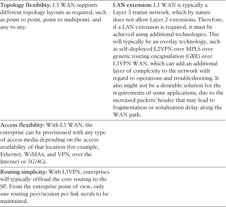
Layer 3 MPLS VPN as a WAN transport enables true any-to-any connectivity between any number of sites without the need for a full mesh of circuits or routing adjacencies. This can offer significant scalability improvements for enterprises with a large number of remote locations. With L3VPN, the provider typically exchanges routing information with enterprise WAN edge routers and forwards packets based on Layer 3 information (IP). In addition, L3VPN service providers (SPs) offer a complete control plane and forwarding plane separation per enterprise (customer), with each enterprise IP service assigned to its own virtual IP network (VPN) within the SP MPLS network. With regard to Layer 2 VPN services, however, the providers typically have no participation in the enterprise Layer 3 WAN control plane. This is because the provider forwards the traffic of any given enterprise based on its Layer 2 information, such as Ethernet MAC addresses.
For the purpose of the CCDE exam, the scenario and the requirements always determine the right choice. There might be situations where both WAN options seem to be equally valid, but typically one of them should be more suitable than the other because of a constraint or a requirement given to you on the exam. However, in some cases, there might be more than one right answer or optimal and suboptimal answers. Therefore, you need to have the right justification to support your design decision (using the logic of why).
Layer 2 MPLS-Based WAN
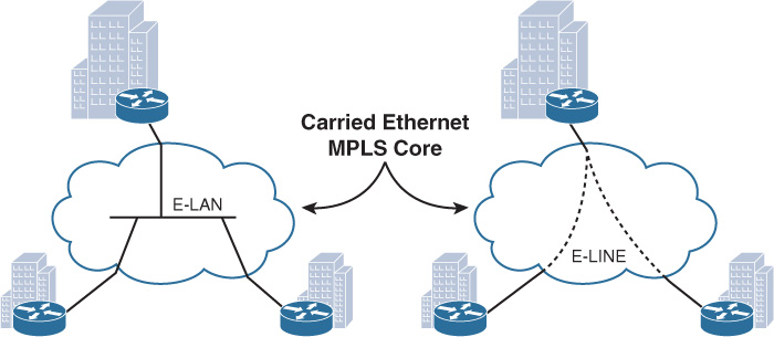
Metro Ethernet (ME) services offered by ME SPs (Carrier Ethernet) are one of the most common Layer 2 WANs used by today’s large enterprises. Layer 2 WAN (ME-based) offers two primary connectivity models for enterprises:
![]() E-Line, also known as Ethernet Virtual Private Line (EVPL), which provides a point-to-point service. With EVPL, the typical physical link is Ethernet (Fast Ethernet or Gigabit Ethernet), and the multiple circuits under one physical link are wired virtually over the ME provider cloud using VLANs as a service identifier.
E-Line, also known as Ethernet Virtual Private Line (EVPL), which provides a point-to-point service. With EVPL, the typical physical link is Ethernet (Fast Ethernet or Gigabit Ethernet), and the multiple circuits under one physical link are wired virtually over the ME provider cloud using VLANs as a service identifier.
![]() E-LAN provides multipoint or any-to-any connectivity, also known as Virtual Private LAN Services (VPLS), and offers any-to-any connectivity with high flexibility for the enterprise WAN.
E-LAN provides multipoint or any-to-any connectivity, also known as Virtual Private LAN Services (VPLS), and offers any-to-any connectivity with high flexibility for the enterprise WAN.
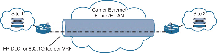
From an enterprise perspective, the Layer 2 (ME) services provided by today’s SPs over their MPLS core infrastructure appear either like a LAN switch for multipoint L2VPN services or like a simple passthrough link for the point-to-point L2VPN sites, as depicted in Figure 4-1.
Although E-Tree is another type of ME connectivity model, it is a variation from E-LAN to provide hub-and-spoke connectivity model.
Note
This section discusses these technologies from the enterprise point of view, as an L2 or L3 WAN solution. Chapter 6, “Service Provider MPLS VPN Services Design,” discusses it from an SP point of view.
Note
L2VPN SPs can preserve the access media using the legacy access media type (such as ATM and Frame Relay) if this is required by the business or if there is a lack of ME coverage by the SP in certain remote areas. In addition, this type of connectivity (mixed) is a common scenario during the migration phase from legacy to modern L2 WAN services.
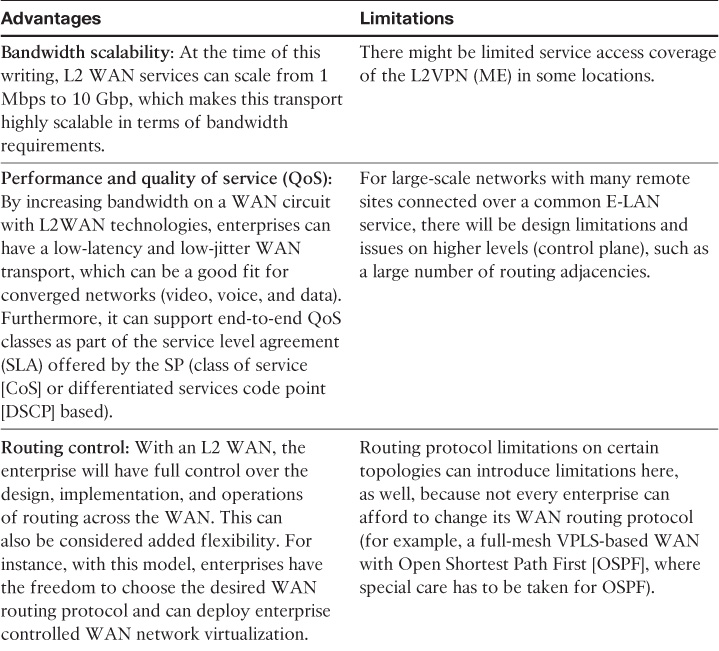
Layer 2 MPLS-Based WAN Advantages and Limitations
Table 4-1 highlights the primary advantages and limitations of a Layer 2 MPLS-based WAN.

There are other variations of ME services, such as Ethernet private line (EPL), that support Ethernet over xWDM (dense wavelength-division multiplexing [DWDM], coarse wavelength-division multiplexing [CWDM]), SONET, or dedicated Ethernet interconnects over fiber. However, this type of service is more expensive than the other ones that are offered by MPLS SPs, such as VPLS or EVPL (Ethernet virtual circuit [EVC]) as an L2VPN ME service.
Layer 3 MPLS-Based WAN
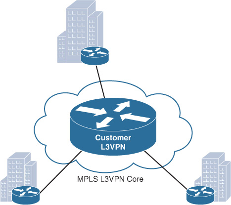
MPLS L3VPN enables enterprise customers to route traffic across the SP cloud as a transit L3 WAN network, with a simplified “one-hop” single routing session per link between the enterprise WAN edge router and provider edge routers. This means that the SP will typically offload all the enterprise WAN control plane complexities in terms of design and operations of the core WAN routing. As a result, enterprises will gain a significant savings in terms of operational expenses and speed up the time to add new remote sites, especially if there hundreds or thousands of remote sites that need to be interconnected. In addition, this model will help to simplify and optimize end-to-end WAN QoS design and bandwidth volume planning of the enterprise WAN connectivity. Figure 4-2 illustrates a Layer 3 MPLS-based WAN. (The MPLS L3VPN cloud appears as single router [peer] from the remote site’s point of view.)
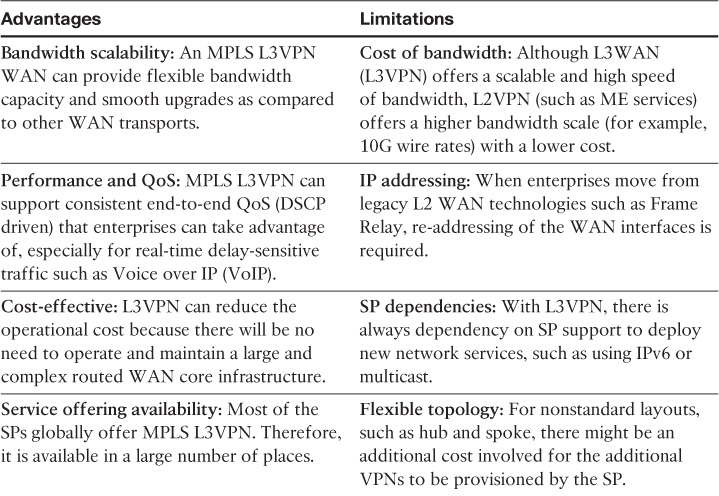
Layer 3 MPLS-Based WAN Advantages and Limitations
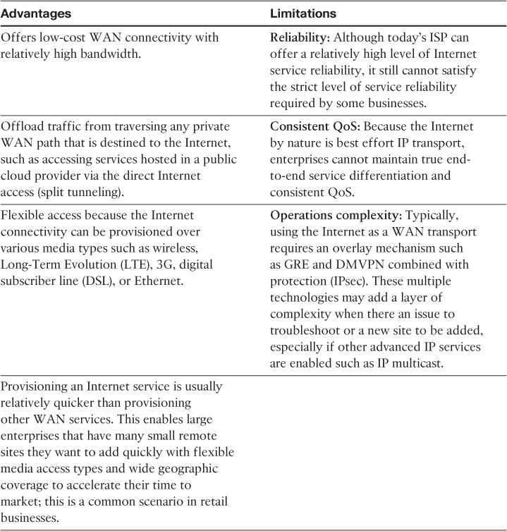
Table 4-2 highlights the primary advantages and limitations of a Layer 3 MPLS-based WAN.
Internet as WAN Transport
Despite the fact that the nature of the Internet is a “best effort transport” that lacks end-to-end QoS support, the modern Internet can offer relatively high reliability and high-speed connectivity between various locations at a low cost. In addition, in today’s modern businesses, many enterprises are increasingly hosting their services in the cloud and embracing many cloud-based services and applications offered as software as a service (SaaS) such as Cisco WebEx and Microsoft Office365, which is changing the traffic pattern to be more toward the Internet.
Furthermore, the Internet can be a reasonable and cost-effective choice for remote sites as a primary transport when it is not feasible to connect over other WAN transport options or when there is a lack of WAN access coverage in certain remote areas. This design primarily relies on using VPN tunneling (overlay) techniques to connect remote sites to the hub site (enterprise WAN module located at the enterprise campus or data center) over the Internet. Ideally, this design is based on a hub-and-spoke connectivity using dynamic multipoint VPN (DMVPN) as the VPN overlay technology for the “Internet as WAN transport” design model, which offers the flexibility to provide any-to-any connectivity as well (direct spoke to spoke). However, point-to-point tunneling mechanisms such as the classical IPsec and GRE are still viable overlay options to be considered (considering typical scalability limitations with peer-to-peer (P2P) tunnels [see Table 4-4 for a detailed comparison of the different VPN mechanisms]). Figure 4-3 depicts the different typical connectivity options available with the Internet as a WAN transport.

The decision of when to use the Internet as a WAN transport and how to use it in terms of level of redundancy and whether to use it as a primary versus backup path depends on the different design requirements, design constraints, and business priorities (see Table 4-4).
Furthermore, Gartner Inc. report “Hybrid Will Be the New Normal for Next Generation Enterprise WAN” analyzes and demonstrates the importance of the integration of the Internet and MPLS WAN to deliver a cohesive hybrid WAN model to meet today’s modern businesses and applications’ trends and requirements such as Cloud-based services. “Network planners must establish a unified WAN with strong integration between these two networks to avoid application performance problems.”1
1. Document ID:G00266397, www.gartner.com
Note
Cisco’s implementation of this (hybrid WAN) concept is called intelligent WAN (IWAN), and combined with Cisco’s intelligent routing is also known as performance routing (PfR), which offers more intelligent path control to protect critical applications and load balance traffic over multiple paths (for example MPLS + Internet) based on predefined criteria to optimize application performance and user experience.
Note
The connectivity to the Internet can be either directly via the enterprise WAN module or through the Internet model (edge). This decision is usually driven by the enterprise security policy, to determine where the actual tunnel termination must happen. For instance, there might be a dedicated demilitarized zone (DMZ) for VPN tunnel termination at the enterprise Internet edge that has a backdoor link to the WAN distribution block to route the decapsulated DMVPN traffic.
Internet as WAN Transport Advantages and Limitations
Table 4-3 highlights the primary advantages and limitations of the Internet as a WAN transport model.
WAN Transport Models Comparison
Table 4-4 summarizes the selection criteria of different WAN transports discussed earlier in this chapter (from an enterprise point of view), considering various design aspects.
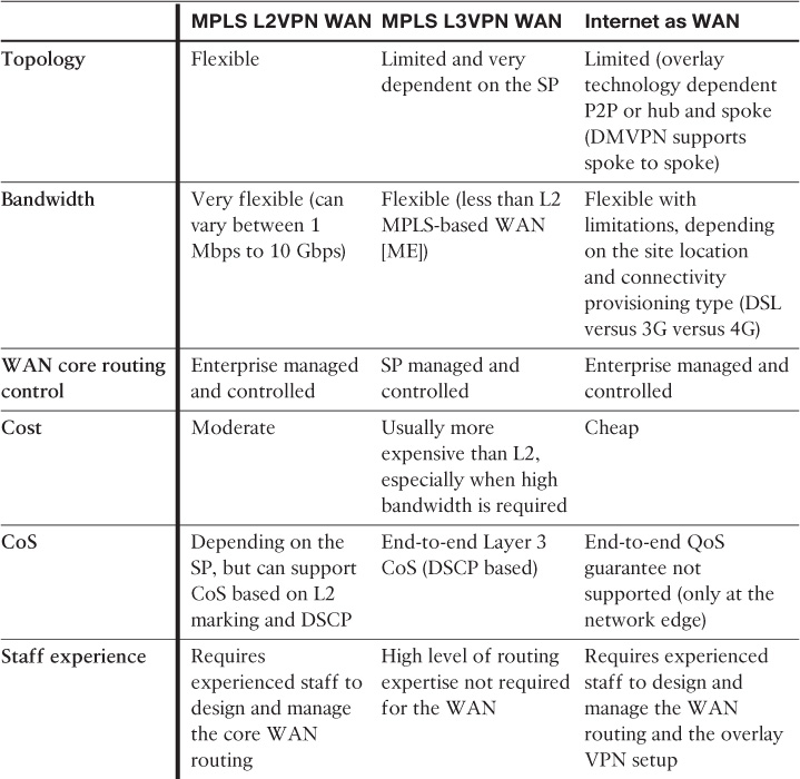
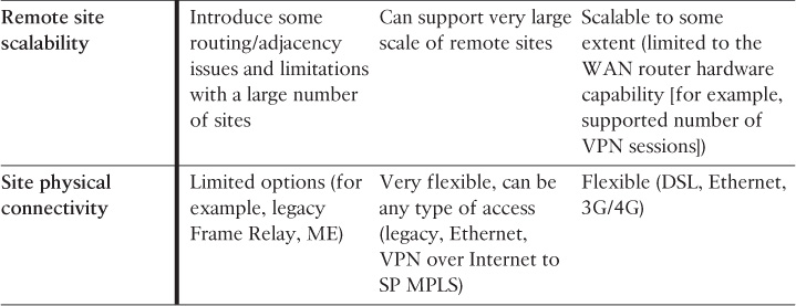
By understanding the differences between each WAN transport and the capabilities and limitations of each transport, network designers should be able to make a more business-driven design decision by mapping the suitable WAN transport to the different design requirements (for example, business, functional, and application). In addition, network designers ideally must consider the answers to the following questions during the planning phase of the WAN transport selection:
![]() Who is responsible for the core WAN routing management?
Who is responsible for the core WAN routing management?
![]() Who manages the customer edge (CE) WAN devices?
Who manages the customer edge (CE) WAN devices?
![]() How critical is the WAN connectivity to the business? What is the impact of an outage on the WAN connectivity to the business in terms of cost and functions?
How critical is the WAN connectivity to the business? What is the impact of an outage on the WAN connectivity to the business in terms of cost and functions?
![]() What is the number of remote sites and what is the percentage of the projected growth, if any?
What is the number of remote sites and what is the percentage of the projected growth, if any?
![]() Are there any budget constraints?
Are there any budget constraints?
![]() What are the required WAN capabilities to transport business applications over the WAN with the desired experience (such as QoS, IP multicast, or IPv6)?
What are the required WAN capabilities to transport business applications over the WAN with the desired experience (such as QoS, IP multicast, or IPv6)?
WAN Module Design Options and Considerations
This section highlights the design considerations and the different WAN connectivity design options that pertain to the enterprise WAN module and remote site WAN connectivity as well [31].
Design Hierarchy of the Enterprise WAN Module
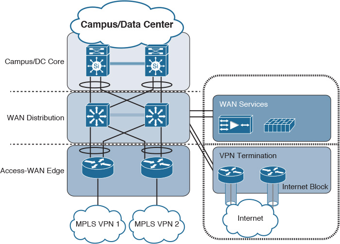
The main goal of the WAN module is to aggregate the connectivity and traffic of the enterprise WAN that connects the enterprise with various types of remote locations. Therefore, this module provides the traffic and connectivity aggregation of the extended remote sites. Applying the hierarchical design principle can maximize the flexibility and scalability of this enterprise module. In addition, this structured approach will simplify adding, removing, and integrating different network nodes and services such as WAN routers, firewalls, and WAN acceleration appliances. As illustrated in Figure 4-4, applying hierarchy will enable each layer to perform certain functions using different features and tools in a more structured manner. Furthermore, the level of flexibility and adaptability offered by the hierarchal structure makes the WAN module design highly scalable and resilient.
WAN Module Access to Aggregation Layer Design Options
The aggregation layer of the WAN module aggregates traffic and connectivity of access layer nodes, which is typically the WAN edge routers and other WAN services, such as firewalls and WAN acceleration appliances.
There are three common design options to interconnect WAN edge routers to the aggregation layer switches of the WAN module, illustrated in Figure 4-5.
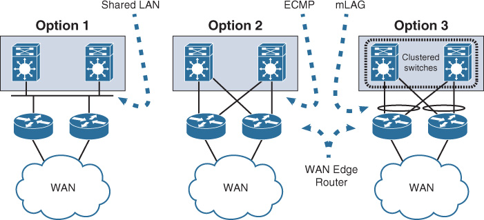
Both design options, 2 (equal-cost multipath [ECMP]) and 3 (multichassis link aggregation [mLAG]), offer a more flexible design compared to Option 1; however, there are some technical differences between these two design options. Table 4-5 summarizes these differences. Although both design options (2 and 3) can achieve the same goal to a large extent, network designers should select the most suitable option based on the environment and required capabilities and features (optimal versus suboptimal).
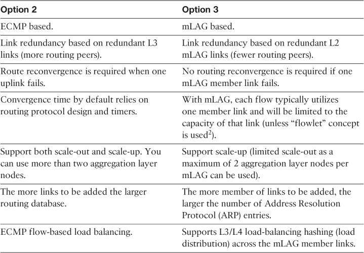
Table 4-5 ECMP Versus mLAG2
2. “Dynamic Load Balancing Without Packet Reordering,” IETF Draft, chen-nvo3-load-banlancing, http://www.ietf.org
Option 1, however, has several design limitations. For instance, without a careful interior gateway protocol (IGP) tuning, this design option can lead to a slow network convergence at the WAN edge, which can result (from a business point of view) in undesirable outcomes after a failure event. In addition, this design option has a potential of instability and scalability when the network grows in terms of nodes connectivity and routing adjacencies (over a single shared LAN segment). In other words, this design option is the least resilient and scalable option among the other design options. Despite that, design option 1 can still meet some design requirements that do not need a tight convergence time or any scalability considerations, such as regional HQ WAN model with only a pair of WAN edge nodes and no future plan to increase the number of nodes or links. Therefore, the requirements always govern which design option is the best, factoring in whether any design constraint may influence the design choice.
WAN Edge Connectivity Design Options
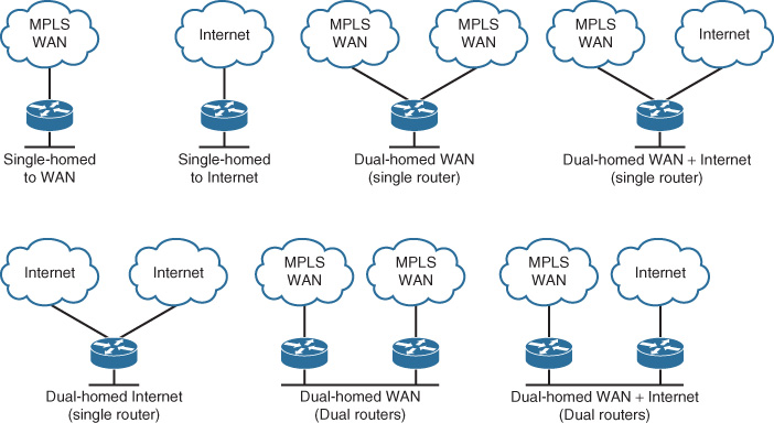
Enterprises can consider several WAN edge connectivity design options, such as single-homed or dual-homed, and using single or dual edge routers. The most important consideration here is to identify the business drivers and requirements that influence the selection of one option over others. Many variables will influence a business-driven design decision to select a specific WAN edge connectivity design option. The most common factors that drive this decision are as follows:
![]() Site type (for example, small branch versus data center versus regional office)
Site type (for example, small branch versus data center versus regional office)
![]() Level of criticality (How much can the downtime cost? How critical is this site to the business if it goes offline for x amount of time?)
Level of criticality (How much can the downtime cost? How critical is this site to the business if it goes offline for x amount of time?)
![]() Traffic load (For example, the load on the HQ data center is more than that of the regional data center.)
Traffic load (For example, the load on the HQ data center is more than that of the regional data center.)
![]() Cost (Is cost-saving a top priority?)
Cost (Is cost-saving a top priority?)
Table 4-6 summarizes the various types of WAN edge connectivity design options depicted in Figure 4-6, along with the different considerations from network design perspective.
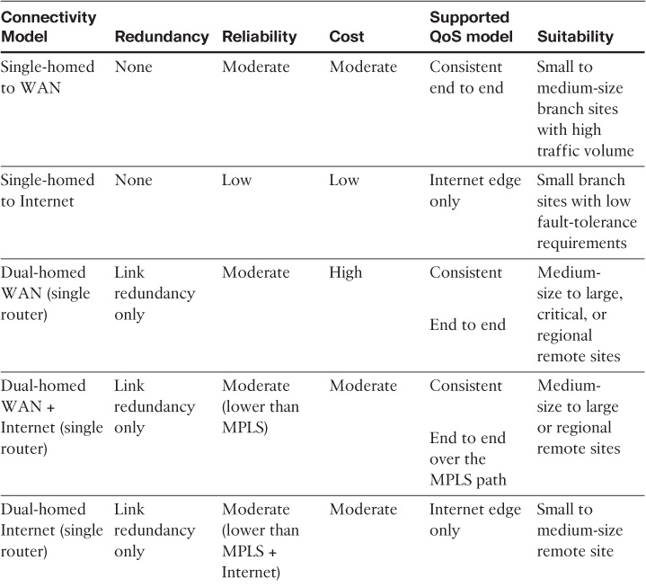
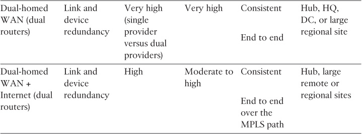
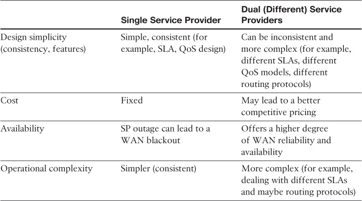
Single WAN Provider Versus Dual Providers
The previous section discussed the various WAN edge design options and the characteristics of each option from a design point of view. This section focuses on the dual WAN edge connectivity, and takes it a step further to compare the impact of connecting a multihomed site to a single SP versus two different SPs, as summarized in Table 4-7.
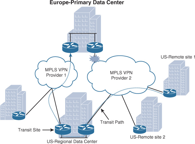
Note
Large enterprises with large geographic distribution can mix between the connectivity options (single versus dual WAN) by using single and dual providers, based on the criticality of the site and business needs. For instance, regional hub sites and data centers can be dual homed to two providers. In addition, this mixed connectivity design approach, where some remote sites are single-homed to a single provider while others are multihomed to dual providers (typically larger sites such data centers or regional HQs), can offer a transit path during a link failure, as depicted in the scenario in Figure 4-7. Ideally the transit site should be located within the same geographic area or country (in the case of global organizations) to mitigate any latency or cost-related issues, when applicable, by reducing the number of international paths traffic has to traverse. In addition, the second provider in Figure 4-7 can be an Internet-based transport such as DMVPN over Internet.
Remote Site (Branch) WAN Design Considerations
The WAN edge design options of a remote site can be based on any of the design options described in the previous section (see Table 4-6), where single or dual WAN edge routers can be used based on the requirements of each particular site. Most commonly, in large enterprises, remote sites are categorized based on different criteria such as size, criticality, location, and typically all the sites under the same categorization follow same design standards.
Note
The edge node is usually either a CE node (for MPLS L3 or Layer 2 WAN) or a VPN spoke node. In some cases, a single WAN edge router can perform the role of both a CE router and VPN spoke router.
However, the level of availability is something that can be determined based on different variables, as discussed in the previous section, such as the level of criticality of the remote site. The rule of thumb for remote site availability is that “the network ideally should tolerate single failure conditions,” either the failure of any single WAN link or any single network device at the hub/HQ WAN side (by considering control plane or overlay failover techniques). However, as discussed earlier in his book, the different business drivers, constraints, and the level of site criticality can drive the level of availability of any given remote site. In other words, remote site availability is not always a requirement or a component that must be considered in the design. In general, remote sites with single-router, dual links must be able tolerate the loss of either of the WAN links. Remote sites with dual router, dual links can tolerate the loss of either a WAN edge router or a WAN link (multiple-failure scenarios).
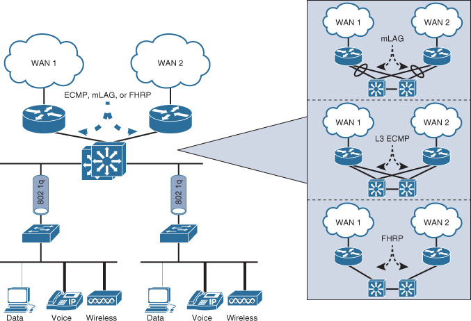
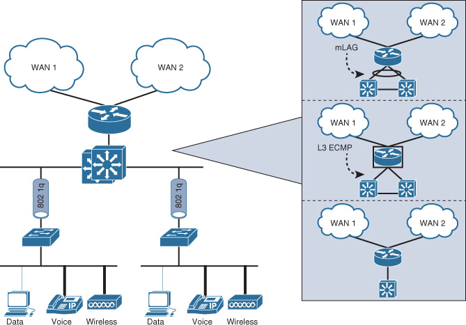
In addition, from a design perspective, the selected WAN connectivity option has a significant influence on the LAN design of a remote site, as does the size of the site (in terms of the number of users and endpoints connected to the network). In general, the design models of a remote site fit into two primary models, as depicted in Figure 4-8 and Figure 4-9 (a and b) and compared in Table 4-8:
![]() Single-tier design model
Single-tier design model
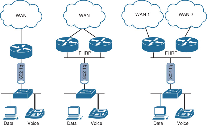
![]() Multitier design model
Multitier design model
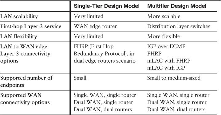
Note
The WAN connectivity options in Table 4-8 apply for both private enterprise WAN or overlaid WAN over the Internet transport.
Internet as WAN Transport (DMVPN Based)
As discussed earlier in this section, using the Internet as a WAN transport in conjunction with DMVPN as the overlay transport offers several benefits to the business and enterprise WAN design, in particular for the remote site WAN connectivity, including the following:
![]() Offers a cost-effective and reliable (to a large extent) WAN connectivity over the Internet
Offers a cost-effective and reliable (to a large extent) WAN connectivity over the Internet
![]() Reduces the time to add new remote sites over various media access types such as DMVPN over Internet over LTE, 3G, or DSL, combined with the support of zero-touch configuration of hub routers when introducing new spokes to the network
Reduces the time to add new remote sites over various media access types such as DMVPN over Internet over LTE, 3G, or DSL, combined with the support of zero-touch configuration of hub routers when introducing new spokes to the network
![]() Provides automatic full-mesh connectivity with simple configuration of hub and spoke
Provides automatic full-mesh connectivity with simple configuration of hub and spoke
![]() Supports (any-to-any) spoke-to-spoke direct connectivity fashion
Supports (any-to-any) spoke-to-spoke direct connectivity fashion
![]() Supports dynamically addressed spokes
Supports dynamically addressed spokes
![]() Supports provisioning behind devices performing Network Address Translation (NAT)
Supports provisioning behind devices performing Network Address Translation (NAT)
![]() Features such as automatic IPsec triggering for building an IPsec tunnel
Features such as automatic IPsec triggering for building an IPsec tunnel
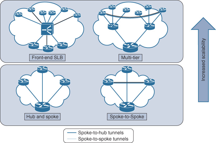
![]() Supports multiple flexible hub-and-spoke design options that serve different design goals, scales, and requirements, as illustrated in Figure 4-10
Supports multiple flexible hub-and-spoke design options that serve different design goals, scales, and requirements, as illustrated in Figure 4-10
Note
Routing over GRE tunnels with large routing tables may require adjustments (normally lowering) to the maximum transmission unit (MTU) value of the tunnel interface.
As illustrated in Figure 4-11, Three primary connectivity options comprise this design model (remote sites DMVPN-based WAN).
![]() Single router, single link
Single router, single link
![]() Single router, dual links
Single router, dual links
![]() Dual routers, dual links
Dual routers, dual links
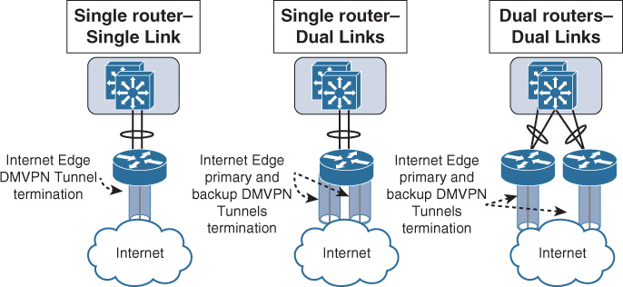
These connectivity options are primarily driven by the desired level of redundancy over the Internet. For instance, the dual routers, dual links connectivity option eliminates any single point of failure at the WAN/Internet edge, and with the single router, dual links, the edge router is posing single point of failure to the design even though there are two redundant Internet links. Therefore, based on the different design requirements and constraints, the best “relevant” option can be selected. For example, if a retailer has a small remote site with a very small number of users that can perform transactions and save them locally in case of any WAN outage, adding redundancy may be considered overengineering in this particular scenario because it will not add significant value to the business, and it may be seen as additional unnecessary cost from the business point of view.
Enterprise WAN Module Design Options
Previous sections in this chapter discussed the design elements and components of the enterprise WAN module. This section highlights the common proven design models you can use as a foundational reference for the enterprise WAN module design, based on the scale of the remote sites [32].
Note
As stated, you can use these design models as foundational reference architecture and scale them based on the requirements. For instance, the design Option 1 model can easily be migrated to design Option 2 when the number of remote sites increases and requires a higher level of redundancy. Similarly, the number of edge access nodes (WAN/Internet edge routers) can be scaled out depending on the design requirements. For instance, an enterprise may consider design Option 1 with an additional redundant edge route to a second MPLS WAN, while the Internet edge router is to be used only as a third level of redundancy with a tunneling mechanism.
Note
The number of remote sites in the following categorization is a rough estimation only (based on the current Cisco Validated Design [CVD] at the time of this writing). Typically, this number varies based on several variables discussed earlier in this book, such as hardware limitations and routing design in terms of number of routes.
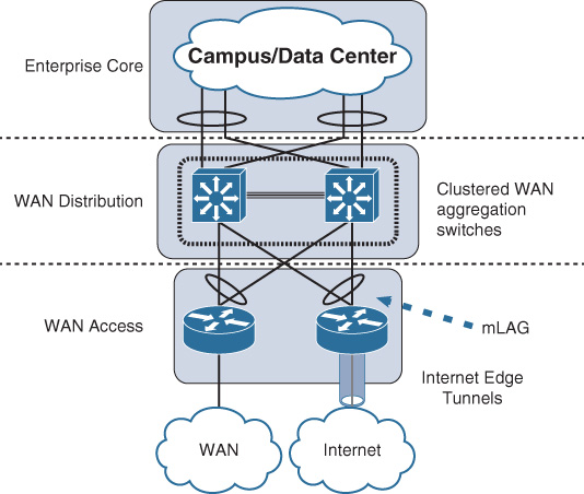
Option 1: Small to Medium
This design option illustrated in Figure 4-12 has the following characteristic:
![]() Dual redundant edge routers.
Dual redundant edge routers.
![]() Single WAN connectivity (primary path).
Single WAN connectivity (primary path).
![]() Single Internet connectivity (backup path over VPN tunnel).
Single Internet connectivity (backup path over VPN tunnel).
![]() Ideally, each of the WAN and Internet routers are dual-homed to the WAN module aggregation clustered switches using Layer 3 over mLAG (or Layer 3 ECMP in case of no switch clustering).
Ideally, each of the WAN and Internet routers are dual-homed to the WAN module aggregation clustered switches using Layer 3 over mLAG (or Layer 3 ECMP in case of no switch clustering).
![]() This design model ideally can support a small to medium number of remote sites (ideally for a few hundred, as a max, taking into account hardware limitations as well).
This design model ideally can support a small to medium number of remote sites (ideally for a few hundred, as a max, taking into account hardware limitations as well).
Option 2: Medium to Large
This design option, illustrated in Figure 4-13, has the following characteristics:
![]() Dual WAN connectivity and dual WAN routers.
Dual WAN connectivity and dual WAN routers.
![]() Dual Internet connectivity and dual Internet routers (typically backup path over VPN tunnel as well as primary for VPN-only remote sites).
Dual Internet connectivity and dual Internet routers (typically backup path over VPN tunnel as well as primary for VPN-only remote sites).
![]() Each of the WAN and Internet routers is dual-homed to the WAN module aggregation clustered switches using Layer 3 over mLAG mLAG (or Layer 3 ECMP in case of no switch clustering).
Each of the WAN and Internet routers is dual-homed to the WAN module aggregation clustered switches using Layer 3 over mLAG mLAG (or Layer 3 ECMP in case of no switch clustering).
![]() This design model supports a medium to large number of remote sites (can support up to few thousand remote sites depending on the hardware capabilities of WAN routers and VPN termination routers).
This design model supports a medium to large number of remote sites (can support up to few thousand remote sites depending on the hardware capabilities of WAN routers and VPN termination routers).
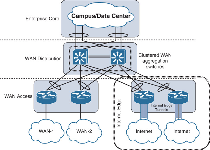
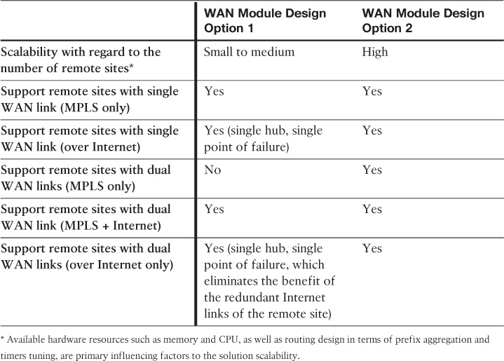
Table 4-9 highlights the supported remote site WAN connectivity design options with regard to the two enterprise WAN design modules discussed earlier.
Option 3: Large to Very Large
This architecture, illustrated in Figure 4-14, targets very large-scale routed WAN deployments. This architecture encompasses branch, metro connectivity, and global core backbones.
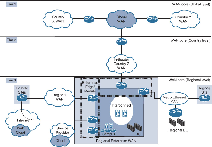
This architecture consists of five primary modules:
![]() Regional WAN: Connects branch offices and aggregates remote locations
Regional WAN: Connects branch offices and aggregates remote locations
![]() Regional MAN: Connects remote offices and data centers across metro area transports
Regional MAN: Connects remote offices and data centers across metro area transports
![]() WAN core: Interconnects regional networks and data centers within a country or theater or globally (provides connectivity between regional enterprises, interconnects within a theater and globally between theaters)
WAN core: Interconnects regional networks and data centers within a country or theater or globally (provides connectivity between regional enterprises, interconnects within a theater and globally between theaters)
![]() Enterprise edge: Connects the enterprise network to other external networks and services (Internet service, mobile service)
Enterprise edge: Connects the enterprise network to other external networks and services (Internet service, mobile service)
![]() Enterprise interconnect: Used as an interconnection and aggregation point for all modules (provides connectivity between the regional WANs, MANs, data centers, enterprise edge, and campus networks)
Enterprise interconnect: Used as an interconnection and aggregation point for all modules (provides connectivity between the regional WANs, MANs, data centers, enterprise edge, and campus networks)
This hierarchical structure offers flexibility for the design to be separated into different element tiers that are suitable to different environments. When a global footprint is required, all the elements of this architecture will likely apply. Whereas with a footprint that is solely within a single theater (region or country), it will not require the global core. However, it can be added when there is a requirement to expand into other regions [28]. The design of each element, such as the regional WAN and remote sites, should follow the design options discussed earlier in this chapter. For example, the regional “enterprise WAN module” can be based on any of the WAN design options discussed earlier in this chapter.
WAN Virtualization and Overlays Design Considerations and Techniques
Chapter 3, “Enterprise Campus Architecture Design,” covered drivers and advantages of considering network virtualization techniques within the enterprise, in particular the enterprise campus network. This section focuses on how the enterprise can extend network virtualization across the WAN to maintain end-to-end path isolation for the different logical networks and groups. Network virtualization over the WAN (WAN virtualization) can be achieved using various approaches and techniques. This section highlights these various design options and the characteristics of each, and suggests uses that can fit different business requirements. One of the primary and common foundational technologies used by enterprises to facilitate achieving WAN virtualization is overlay technologies. In fact, overlay (also referred to as self-deployed VPN) technologies are adopted by businesses to serve different purposes, from enterprise an network design perspective, such as the following:
![]() Build a cost-effective WAN model also known as Internet as WAN transport model (virtual private WAN). You can use this model either as a primary or backup WAN transport.
Build a cost-effective WAN model also known as Internet as WAN transport model (virtual private WAN). You can use this model either as a primary or backup WAN transport.
![]() Provide a mechanism to maintain end-to-end path isolation for logical groups or entities across the enterprise WAN.
Provide a mechanism to maintain end-to-end path isolation for logical groups or entities across the enterprise WAN.
![]() Secure IP communications over the private enterprise WAN or Internet.
Secure IP communications over the private enterprise WAN or Internet.
![]() Provide a controlled remote-access method for mobile users or third-party entities that might require access to certain internal resources.
Provide a controlled remote-access method for mobile users or third-party entities that might require access to certain internal resources.
![]() Provide overlaid transport for services and applications that are not supported by the underlay transport infrastructure, such as multicast-based applications and IPv6 applications over “unicast-only” IPv4 IP network.
Provide overlaid transport for services and applications that are not supported by the underlay transport infrastructure, such as multicast-based applications and IPv6 applications over “unicast-only” IPv4 IP network.
Therefore, it is critical that network designers have a very good understanding of the different overlay (VPN) options in terms of supported design models, strengths, limitations, and suitable use cases.
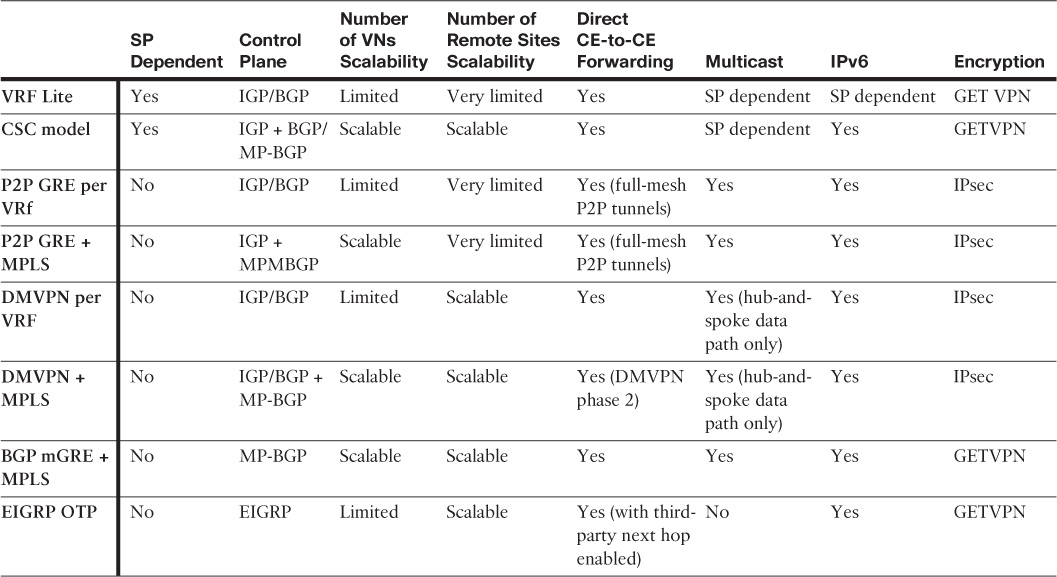
Table 4-10 compares the different overlay (VPN) technologies that commonly used to extend enterprise connectivity and facilitate network virtualization over IP transport networks.
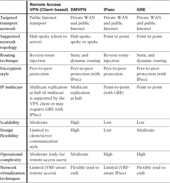
The primary scalability limiting factor of any VPN solution is the support number of sessions by the used hardware platform.
Note
GET VPN is an encryption mechanism that enables you to preserve IP header information that supports true “any-to-any” encrypted IP connectivity model. Therefore, it is commonly used over private transport networks such a private WAN instead of the other IP tunneling mechanisms. Having said that, GETVPN is not always the ideal or optimal overlay and encryption solution over the private WAN. For example, if the existing WAN platforms of an organization do not support GETVPN (and the business has no intention or plan to upgrade any network hardware/software), then you need to deal with the design constraints and consider other options here, such as IPSec with GRE or mGRE.
These different VPN technologies highlighted in Table 4-10 are the foundation of achieving WAN virtualization. However, modern large-scale enterprises can use other approaches to maintain end-to-end path separation, such as “self-deployed” MPLS L3VPN. The following section classifies, discusses, and compares all the different primary technologies and design options that can help you achieve WAN virtualization to suit different design requirements.
WAN Virtualization
Introducing virtualization and path isolation over the WAN transport is commonly driven by the adoption of the network virtualization concept by the enterprise within the campus LAN, branches, or data center network. Therefore, to maintain end-to-end path isolation, network virtualization must be extended over the WAN transport in a manner that does not compromise path-isolation requirements. From a WAN design point of view, two primary WAN connectivity models drive the overall WAN virtualization design choices:
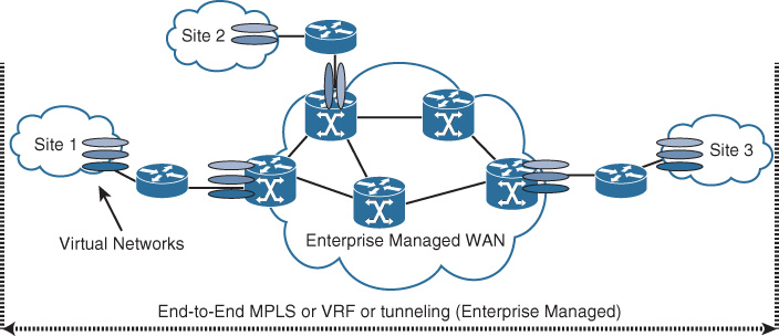
![]() Customer- or enterprise-controlled WAN: Also known as self-deployed, this model provides full control for the enterprise to use the desired core routing design and the type of virtualization techniques that meet their requirements, such as MPLS in the core or tunneling with multiple VRFs. Furthermore, all the techniques discussed in the campus enterprise virtualizations section are applicable. Typically, this model is based on the fact that the enterprise controls the WAN core infrastructure or transport, as depicted in Figure 4-15.
Customer- or enterprise-controlled WAN: Also known as self-deployed, this model provides full control for the enterprise to use the desired core routing design and the type of virtualization techniques that meet their requirements, such as MPLS in the core or tunneling with multiple VRFs. Furthermore, all the techniques discussed in the campus enterprise virtualizations section are applicable. Typically, this model is based on the fact that the enterprise controls the WAN core infrastructure or transport, as depicted in Figure 4-15.
Note
If the WAN SP in the middle provides L2 WAN transport, it can be categorized under the enterprise-controlled WAN model, because the enterprise will have the control and freedom, to a large extent, to deploy the desired end-to-end WAN virtualization techniques based on the business and technical requirements, such as MPLS-enabled virtualization or subinterfaces with VRFs, as illustrated in Figure 4-16.
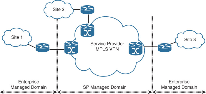
![]() SP-controlled WAN: This model, compared to the previous model, provides the least control for the enterprise when it comes to routing an end-to-end network virtualization over an SP-controlled WAN transport, such as MPLS L3VPN, as depicted in Figure 4-17. Therefore, enterprises need to either extend the virtualization to the SP (to the PE node) or build an overlay over the SP managed network between their CE nodes to facilitate the formation of the required end-to-end network virtualization. This approach is commonly referred to as over the top.
SP-controlled WAN: This model, compared to the previous model, provides the least control for the enterprise when it comes to routing an end-to-end network virtualization over an SP-controlled WAN transport, such as MPLS L3VPN, as depicted in Figure 4-17. Therefore, enterprises need to either extend the virtualization to the SP (to the PE node) or build an overlay over the SP managed network between their CE nodes to facilitate the formation of the required end-to-end network virtualization. This approach is commonly referred to as over the top.
Over-the-Top WAN Virtualization Design Options (Service Provider Coordinated/Dependent)
The following design options require coordination with the SP to support extending the enterprise network virtualization over the MPLS L3VPN provider network. The two common and proven approaches used to extend network virtualization of an enterprise over unmanaged L3VPN SP network are as follows:
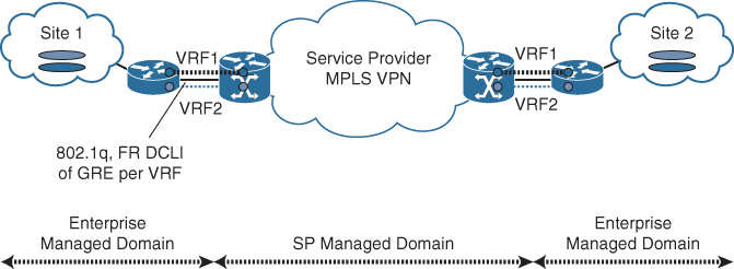
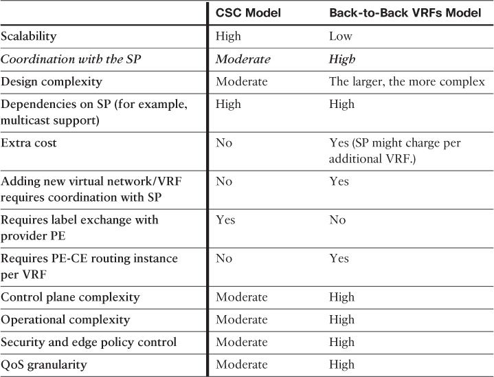
![]() Back-to-back VRFs to provider PE: This approach is based on using the concept of Multi-VRF CE. This approach provides L3 path virtualization extension without exchanging labels over IP tunnels or physical interfaces (subinterfaces) with the provider PE, as illustrated in Figure 4-18. Typically, a routing instance (process) per VRF is required at each CE and PE node to exchange routing information per virtual network.
Back-to-back VRFs to provider PE: This approach is based on using the concept of Multi-VRF CE. This approach provides L3 path virtualization extension without exchanging labels over IP tunnels or physical interfaces (subinterfaces) with the provider PE, as illustrated in Figure 4-18. Typically, a routing instance (process) per VRF is required at each CE and PE node to exchange routing information per virtual network.
![]() Enable MPLS (Label Distribution Protocol [LDP]) with provider PE: This approach is based on the Carrier Supporting Carrier design model (CSC, RFC 3107), where the CE node can send packets along with MPLS label to the provider PE, which ultimately can facilitate for enterprises the formation of their own multiprotocol BGP (MP-BGP) peering across the SP MPLS L3VPN backbone, as illustrated in Figure 4-19.
Enable MPLS (Label Distribution Protocol [LDP]) with provider PE: This approach is based on the Carrier Supporting Carrier design model (CSC, RFC 3107), where the CE node can send packets along with MPLS label to the provider PE, which ultimately can facilitate for enterprises the formation of their own multiprotocol BGP (MP-BGP) peering across the SP MPLS L3VPN backbone, as illustrated in Figure 4-19.
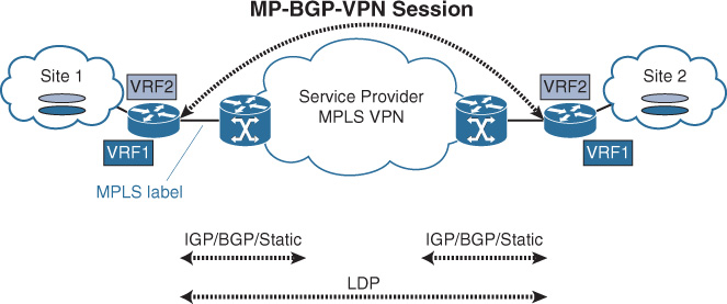
Table 4-11 compares these two design approaches from different design angles.
Over-the-Top WAN Virtualization Design Options (Service Provider Independent)
This section discusses the different design options that use various overlay approaches, which can facilitate the extension of an enterprise network virtualization over an unmanaged L3 SP WAN. Unlike the approaches discussed in the previous section, the design options discussed in this section are end-to-end controlled and deployed by the customer or enterprise side without any coordination/dependencies with the WAN SP (simply because all the methods are based on the concept of using different tunneling [overlay] mechanisms that typically encapsulate and hide all the traffic and virtualization setup from the underlying SP transport network):
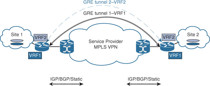
![]() Point-to-point GRE tunnel per VRF: This design option offers a simple private virtual network extension over GRE tunnels, where each GRE tunnel is assigned to a specific VRF per virtual network, without any need to coordinate with the WAN provider. However, this option can introduce operations and setup complexities in large deployments because of the large number of manual configurations of the point-point tunnels, each with its own control plane. In addition, this design option has the least scalability, because the number of tunnels can increase significantly when the number of sites and VRFs increases. For example, 60 sites with 3 VRFs each will require (N – 1) tunnel per VRF, (59 * 3) = 177 tunnels to create. Nevertheless, this design option can be a good choice for traffic isolation between a very small number of sites (ideally two or three sites only) with a very limited number of VRFs (ideally two or three) VRFs, as illustrated in Figure 4-20.
Point-to-point GRE tunnel per VRF: This design option offers a simple private virtual network extension over GRE tunnels, where each GRE tunnel is assigned to a specific VRF per virtual network, without any need to coordinate with the WAN provider. However, this option can introduce operations and setup complexities in large deployments because of the large number of manual configurations of the point-point tunnels, each with its own control plane. In addition, this design option has the least scalability, because the number of tunnels can increase significantly when the number of sites and VRFs increases. For example, 60 sites with 3 VRFs each will require (N – 1) tunnel per VRF, (59 * 3) = 177 tunnels to create. Nevertheless, this design option can be a good choice for traffic isolation between a very small number of sites (ideally two or three sites only) with a very limited number of VRFs (ideally two or three) VRFs, as illustrated in Figure 4-20.
Note
For this design option and the subsequent ones, it is hard to generalize and provide a specific recommended number of remote sites or VRFs, because the decision has to be made based on these two variables when measuring the scalability of the design option. For example, evaluating this design option for a network that requires path isolation between 3 sites, where each site has 10 different virtual networks to transport, is different from when there are 3 sites with 2 virtual networks in each. In both cases, the number of sites is small; however, the number of VRFs (virtual networks) here becomes the tiebreaker:
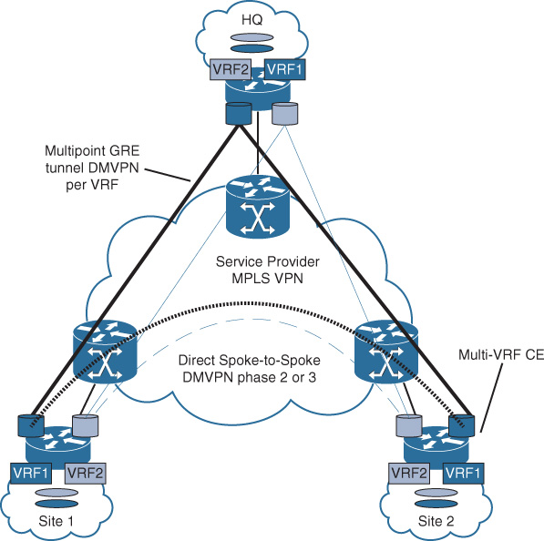
![]() Dynamic multipoint GRE (DMVPN) per VRF: This design option is typically based on using multipoint GRE tunnels (DMVPN) per virtual network, as illustrated in Figure 4-21, which helps to overcome some of the scalability issues of the previous option to some extent. This design option also supports direct spoke-to-spoke traffic forwarding (bypassing the hub) per VRF. Furthermore, it supports deployments of a larger scale than those of the point-to-point GRE tunnels. However, it still has scalability and operational limitations and complexities when the network grows, because there will be a DMVPN cloud per VRF. This means that the greater the number of VRFs required, the greater the number of DMVPN clouds that need to be created and operated with a separate control plane for each. This design option ideally supports the following design combinations:
Dynamic multipoint GRE (DMVPN) per VRF: This design option is typically based on using multipoint GRE tunnels (DMVPN) per virtual network, as illustrated in Figure 4-21, which helps to overcome some of the scalability issues of the previous option to some extent. This design option also supports direct spoke-to-spoke traffic forwarding (bypassing the hub) per VRF. Furthermore, it supports deployments of a larger scale than those of the point-to-point GRE tunnels. However, it still has scalability and operational limitations and complexities when the network grows, because there will be a DMVPN cloud per VRF. This means that the greater the number of VRFs required, the greater the number of DMVPN clouds that need to be created and operated with a separate control plane for each. This design option ideally supports the following design combinations:
![]() Large number of remote sites with very small number of VRFs (ideally two)
Large number of remote sites with very small number of VRFs (ideally two)
![]() Small number of remote sites with small number of VRFs (ideally not more than three)
Small number of remote sites with small number of VRFs (ideally not more than three)
![]() MPLS over point-to-point GRE tunnel: This design option is based on the concept of encapsulating MPLS labels in a GRE tunnel, as described in RFC 4023, which helps to overcome some of the limitations of the point-to-point GRE tunnel per VRF design option, by using MPLS with an MP-BGP VPNv4/6 session over one GRE tunnel (RFC 2547 MP-BGP control plane style), as depicted in Figure 4-22. Consequently, there will be only one GRE tunnel required to carry LDP, IGP, and MP-BGP (VPNv4/6). Typically, there is no need to create a separate GRE tunnel per VRF with this design option. However, the number of remote sites is still a limiting factor in the scalability of this design option in the case where many remote sites need to be connected, either in a fully meshed manner or using hub-and-spoke overlay topology.
MPLS over point-to-point GRE tunnel: This design option is based on the concept of encapsulating MPLS labels in a GRE tunnel, as described in RFC 4023, which helps to overcome some of the limitations of the point-to-point GRE tunnel per VRF design option, by using MPLS with an MP-BGP VPNv4/6 session over one GRE tunnel (RFC 2547 MP-BGP control plane style), as depicted in Figure 4-22. Consequently, there will be only one GRE tunnel required to carry LDP, IGP, and MP-BGP (VPNv4/6). Typically, there is no need to create a separate GRE tunnel per VRF with this design option. However, the number of remote sites is still a limiting factor in the scalability of this design option in the case where many remote sites need to be connected, either in a fully meshed manner or using hub-and-spoke overlay topology.
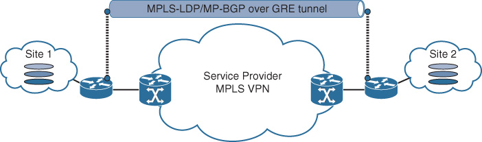
Furthermore, this design option can help simplify the interconnection of disjoint MPLS-enabled infrastructures over a native IP backbone. As illustrated in Figure 4-23, MPLS over GRE is used to extend the reachability between two MPLS-enabled islands over a non-MPLS backbone (native IP).
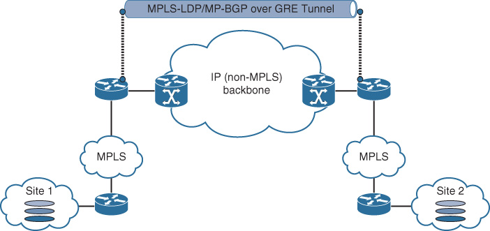
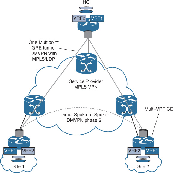
![]() MPLS over dynamic multipoint GRE (DMVPN): This design option, also known as 2547oDMVPN, is based on using MPLS over DMVPN tunnels (standard RFC 2547 MP-BGP control plane), which allows MPLS VPN to leverage the DMVPN framework (Next Hop Resolution Protocol [NHRP] for dynamic endpoint discovery). Compared to the (DMVPN per VRF) design option, using MPLS over the DMVPN will help to avoid having a DMVPN cloud per VRF. In other words, there will be one DMVPN cloud (carrying LDP, IGP, MP-BGP VPNv4) to transport all the VRFs between the different locations (sites) in a hub-and spoke-topology, as illustrated in Figure 4-23. This makes it a very scalable solution for large hub-and-spoke deployments with multiple distributed virtual networks. Also, this option supports direct spoke-to-spoke communication. (At the time of this writing, DMVPN phase 2 for direct dynamic spoke-to-spoke communication is achievable.3). Multicast traffic, however, must traverse the hub site if enabled.
MPLS over dynamic multipoint GRE (DMVPN): This design option, also known as 2547oDMVPN, is based on using MPLS over DMVPN tunnels (standard RFC 2547 MP-BGP control plane), which allows MPLS VPN to leverage the DMVPN framework (Next Hop Resolution Protocol [NHRP] for dynamic endpoint discovery). Compared to the (DMVPN per VRF) design option, using MPLS over the DMVPN will help to avoid having a DMVPN cloud per VRF. In other words, there will be one DMVPN cloud (carrying LDP, IGP, MP-BGP VPNv4) to transport all the VRFs between the different locations (sites) in a hub-and spoke-topology, as illustrated in Figure 4-23. This makes it a very scalable solution for large hub-and-spoke deployments with multiple distributed virtual networks. Also, this option supports direct spoke-to-spoke communication. (At the time of this writing, DMVPN phase 2 for direct dynamic spoke-to-spoke communication is achievable.3). Multicast traffic, however, must traverse the hub site if enabled.
3. Advanced DMVPN & Routing Fun in the Lab: Part 2 – The Forwarding Plane, http://www.networkingwithfish.com
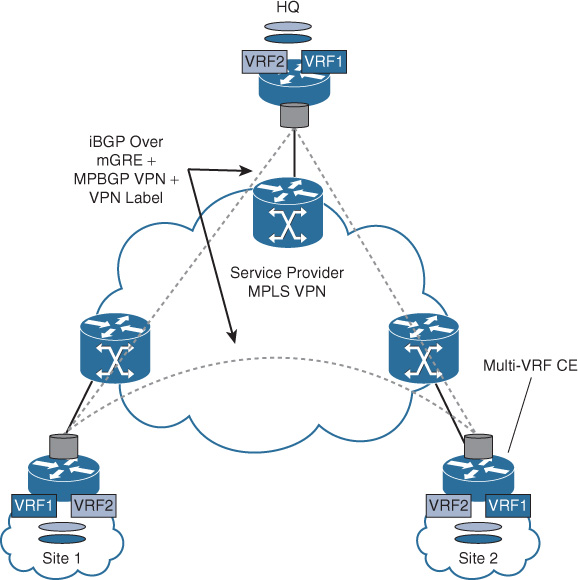
![]() MPLS over multipoint GRE (using BGP for endpoint discovery): MPLS over mGRE simplifies the design and implementation of overlaid (self-deployed) MPLS VPN using the standard RFC 2547 MP-BGP control plane, which offers dynamic tunnel endpoint discovery using BGP as the control plane. This solution requires only one IP address (typically a loopback address) of each of the enterprise CE routers to be advertised to the interconnecting SP cloud network, as depicted in Figure 4-25. In addition, there is no requirement to manually configure any GRE tunnel or enable LDP/RSVP (Resource Reservation Protocol) on any interface. Instead, mGRE encapsulation is automatically generated with the dynamic endpoint discovery capability. The VPNv4 label and VPN payload are carried over the mGRE tunnel encapsulation. This solution offers a simplified and scalable any-to-any unicast (IPv4, IPv6 6VPE based) and multicast (MDT based) MPLS VPN communication model.
MPLS over multipoint GRE (using BGP for endpoint discovery): MPLS over mGRE simplifies the design and implementation of overlaid (self-deployed) MPLS VPN using the standard RFC 2547 MP-BGP control plane, which offers dynamic tunnel endpoint discovery using BGP as the control plane. This solution requires only one IP address (typically a loopback address) of each of the enterprise CE routers to be advertised to the interconnecting SP cloud network, as depicted in Figure 4-25. In addition, there is no requirement to manually configure any GRE tunnel or enable LDP/RSVP (Resource Reservation Protocol) on any interface. Instead, mGRE encapsulation is automatically generated with the dynamic endpoint discovery capability. The VPNv4 label and VPN payload are carried over the mGRE tunnel encapsulation. This solution offers a simplified and scalable any-to-any unicast (IPv4, IPv6 6VPE based) and multicast (MDT based) MPLS VPN communication model.
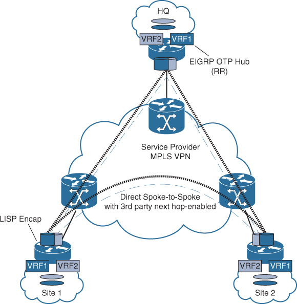
![]() EIGRP Over the Top (OTP): As the name implies, EIGRP OTP offers enterprise customers the opportunity to form EIGRP adjacencies across unmanaged WAN transport (typically over an L3VPN MPLS provider cloud) using unicast packets for peering and exchanging route prefixes without being injected into the provider’s MP-BGP VPNv4/v6 routing table. With this approach, EIGRP OTP offers simplified dynamic multipoint encapsulation using Locator/ID Separation Protocol (LISP) to encapsulate its data traffic. EIGRP OTP relies on EIGRP routing tables rather than on the LISP mapping system to populate IP routing information. Furthermore, multiple instances of EIGRP can be deployed, along with other network virtualization techniques, to offer multiple routing instances.
EIGRP Over the Top (OTP): As the name implies, EIGRP OTP offers enterprise customers the opportunity to form EIGRP adjacencies across unmanaged WAN transport (typically over an L3VPN MPLS provider cloud) using unicast packets for peering and exchanging route prefixes without being injected into the provider’s MP-BGP VPNv4/v6 routing table. With this approach, EIGRP OTP offers simplified dynamic multipoint encapsulation using Locator/ID Separation Protocol (LISP) to encapsulate its data traffic. EIGRP OTP relies on EIGRP routing tables rather than on the LISP mapping system to populate IP routing information. Furthermore, multiple instances of EIGRP can be deployed, along with other network virtualization techniques, to offer multiple routing instances.
This design approach offers significant design flexibility for enterprise WAN connectivity because WAN networks will be seen as a virtual extension of the network and enterprise customers can simply and transparently extend their infrastructure reachability over the provider’s network using one unified control plane protocol, as shown in Figure 4-26.
Comparison of Enterprise WAN Transport Virtualization Techniques
Table 4-12 provides a summarized comparison, from different design aspects, between the different WAN virtualization techniques discussed in this chapter.
Operational complexity always increases when the network size increases and the WAN virtualization techniques used have limited scalability support and vice versa.
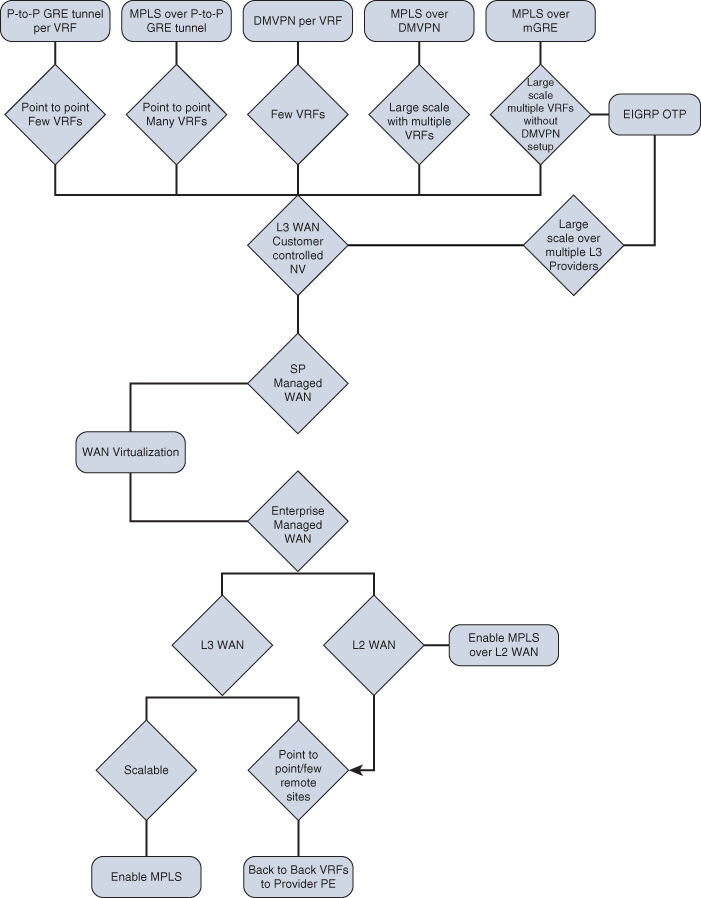
WAN Virtualization Design Options Decision Tree
Figure 4-27 is a summarized decision tree of the different design options for enterprise WAN virtualization.
Enterprise WAN Migration to MPLS VPN Considerations
Network migration is one of the most challenging and critical projects of network design. Network designers sometimes spend a large amount of time focusing on the “end state” of their network designs. However, a good and successful design must consider a migration strategy to move the network from its current state to the new state. Similarly, a good migration plan should address how network control plane protocols and applications will interact when the network is partially migrated.
It is impossible to provide general definite guidance for network migration because many variables drive and influence the migration plan and its strategy, such as business and application requirements, network size, and the technologies used. However, the following are some approaches and rules of thumb based on proven WAN migration experiences that should be considered when generating strategic or tactical migration plans:
![]() The phased migration approach is always recommended for large-scale networks with a large number of remote sites where multiple links or external exit points might exist.
The phased migration approach is always recommended for large-scale networks with a large number of remote sites where multiple links or external exit points might exist.
![]() Logical and physical site architecture must be analyzed and taken into consideration during the planning phase, such as backdoor links, OSPF areas if the PE-CE protocol is OSPF, and BGP autonomous system (AS) numbering if BGP is used across the remote sites.
Logical and physical site architecture must be analyzed and taken into consideration during the planning phase, such as backdoor links, OSPF areas if the PE-CE protocol is OSPF, and BGP autonomous system (AS) numbering if BGP is used across the remote sites.
![]() In L3VPN, review the selected PE-CE routing protocol and consider how it can integrate with the existing routing setup and design without introducing any service interruption after moving to the new MPLS cloud.
In L3VPN, review the selected PE-CE routing protocol and consider how it can integrate with the existing routing setup and design without introducing any service interruption after moving to the new MPLS cloud.
![]() It is important to identify where the default route is generated and whether the remote sites will use a locally generated default route or over the MPLS cloud.
It is important to identify where the default route is generated and whether the remote sites will use a locally generated default route or over the MPLS cloud.
![]() Review the routing and identify the places that have summarization because, in some situations, this may lead to suboptimal routing or route summarization black holes.
Review the routing and identify the places that have summarization because, in some situations, this may lead to suboptimal routing or route summarization black holes.
![]() In L2VPN, there might be different topologies that can be provisioned by the provider (hub and spoke, full mesh, or partial mesh). A careful review of the topology and the effect of the path that traffic will take after the migration is very important, especially if you are moving from one topology to another. For example, you may be migrating the WAN from a hub-and-spoke topology over Frame Relay to a full-mesh L2 WAN (for example, VPLS).
In L2VPN, there might be different topologies that can be provisioned by the provider (hub and spoke, full mesh, or partial mesh). A careful review of the topology and the effect of the path that traffic will take after the migration is very important, especially if you are moving from one topology to another. For example, you may be migrating the WAN from a hub-and-spoke topology over Frame Relay to a full-mesh L2 WAN (for example, VPLS).
Migrating from Legacy WAN to MPLS L3VPN WAN Scenario
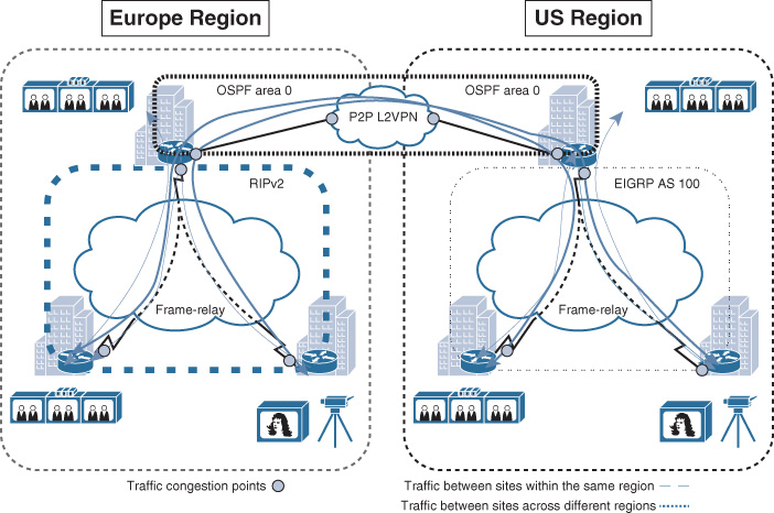
This section provides an example of a phased migration approach based on a migration scenario of an international media company that is currently using two separate Layer 2 (Frame Relay) clouds over hub-and-spoke topology across two different geographic regions (the United States and Europe). In addition, the hub sites of both the U.S. and Europe regions are interconnected over a Layer 2 virtual leased line (VLL) provisioned by an international Carrier Ethernet, as illustrated in Figure 4-28. After this media company finished a recent migration project of their video and broadcasting systems from a legacy time-division multiplexing (TDM)-based solution to an IP-based solution, they started facing degraded video quality because of the increased number of packets lost and delayed across the WAN. The obvious cause of this issue is the large number of video streams across the low-capacity Frame Relay WAN links and because of the long trip each video stream has to take to reach its intended destination. For instance, traffic between two sites located within the same region has to traverse the hub site first. In addition, traffic between sites across different regions has to traverse the local and remote hub sites over the VLL link, as shown in Figure 4-28. Therefore, to overcome these limitations, a decision has been made to migrate the current hub-and-spoke Frame Relay WAN to an any-to-any topology over a single global MPLS L3VPN provider, to meet current traffic flow requirements with regard to the available bandwidth and delay and to achieve more consistent end-to-end QoS.
Current state
![]() WAN is based on hub-and-spoke topology over Frame Relay.
WAN is based on hub-and-spoke topology over Frame Relay.
![]() EIGRP is the routing protocol used over the U.S. region WAN.
EIGRP is the routing protocol used over the U.S. region WAN.
![]() RIPv2 is the routing protocol used over the Europe region WAN.
RIPv2 is the routing protocol used over the Europe region WAN.
![]() OSPF is the routing protocol used by each hub site and between the hub sites over the VLL.
OSPF is the routing protocol used by each hub site and between the hub sites over the VLL.
![]() OSPF area 0 is used over the VLL and each hub LAN network.
OSPF area 0 is used over the VLL and each hub LAN network.
![]() External BGP (eBGP) is the proposed protocol to be used over the new MPLS L3VPN WAN.
External BGP (eBGP) is the proposed protocol to be used over the new MPLS L3VPN WAN.
Assumption: WAN IP addressing and the desired amount of bandwidth per site is organized with the MPLS VPN provider before the migration starts.
Migration steps
Step 1. (Illustrated in Figure 4-29):
a. Select the hub site to act as the transit site during this migration process (per region).
b. Establish physical connectivity between the hub site (per region) and the new MPLS L3VPN SP.
c. Establish an eBGP session between the hub (CE) and the SP (PE).
d. Configure redistribution between OSPF and BGP at each hub site.

Note
After the migration to the MPLS VPN, there will be two points of route redistribution with a backdoor link (over the L2VPN link between the hub sites). This scenario may introduce some route looping or suboptimal routing. Therefore, it is advised that over this L2VPN link each hub site (ASBR) advertises only the summary routes and not the specific to ensure that the MPLS WAN path is always preferred (more specific) without potential routing information looping. Alternatively, route filtering, as discussed in Chapter 2, “Enterprise Layer 2 and Layer 3 Design” (in the “Route Redistribution” section) must be considered.
Traffic between the LAN networks of each hub site will use the VLL (L2VPN) path as the primary path. Because the HQ LAN networks, along with the VLL link, are all part of the same area (area 0), the summarization at the hub (Autonomous System Border Router [ASBR]) routers will not be applicable here (same area). By reducing OSPF cost over the VLL link, you can ensure that traffic between the HQ LANs will always use this path as the primary path.
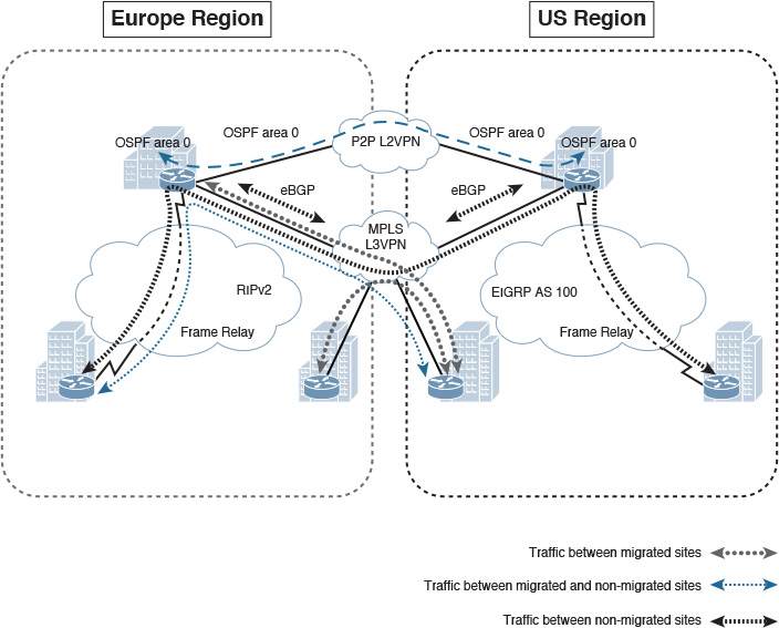
Step 2. (Illustrated in Figure 4-30):
a. Connect one of the spoke routers intended to be migrated to the MPLS VPN.
b. Establish an eBGP session with MPLS VPN SP and advertise the local subnet (LAN) using the BGP network statement (ideally without route retribution).
c. Once the traffic starts flowing via the MPLS VPN (eBGP has a lower AD 20), disconnect the Frame Relay link.
d. At this stage, traffic between migrated spokes and nonmigrated spokes will flow via the transit hub site.
Step 3. Migrate the remaining spokes using the same phased approach.
Note
With this approach, connectivity will be maintained between the migrated and nonmigrated sites without introducing any service interruption until the migration of the remaining remote sites is completed.
Enterprise Internet Edge Design Considerations
The Internet edge is another module or block of the modular enterprise architecture and part of the enterprise edge module, which provides external connectivity to the other places in the network (PINs) across the enterprise. The Internet block in particular acts as a gateway to the Internet for the enterprise network. From a design point of view, the Internet edge design may significantly vary between organizations, because it is typically driven by the security policy of the business. In addition, large enterprises typically put the Internet edge or module either collocated within the campus network or within its data center network. Nevertheless, in both cases, the location will not impact the module design itself; it will only change the overall enterprise architecture and traffic flow. Therefore, the design concepts discussed in this section apply to both scenarios (location neutral, whether the Internet block is located within the campus or within the data center).
Internet Edge Architecture Overview
To a large extent, the Internet edge design will vary between different networks based on the security policy of the organization and industry type. For instance, financial services organizations tend to have sophisticated multilayer Internet edge design. In contrast, retail businesses usually have a less-complicated Internet edge design. Consequently, this can lead to a significant difference in the design, which makes it impractical to provide specific design recommendations for this block. However, Figure 4-31 illustrates a typical (most common) Internet block foundational architecture. It highlights the main layers and network components that form this module as part of the overall modular enterprise architecture.
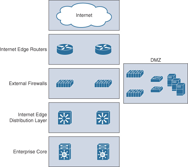
This block should ideally follow the same principle of the hierarchical design model as part of the modular enterprise building block architecture. This hierarchical model offers a high level of flexibility to this block by having different layers, each focused on different functions. The distribution layer in this block aggregates all the communications within the block, and between the enterprise core and the Internet block, by providing a more structured design and deterministic traffic flow. This flexible design can be considered foundational architecture. It can then be changed or expanded as needed. For example, the demilitarized zone (DMZ) in Figure 4-29 can be replicated into multiple DMZs to host different services that require different security policies and physical separation. Some designs also place the VPN termination point in a separate DMZ for an additional layer of security and control.
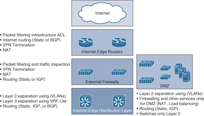
Figure 4-32 highlights the typical primary functions and features at each layer of the Internet block architecture.
Note
These functions can vary from design to design to some extent. Moreover, all of them are not necessarily required to be applied. For example, NAT can be applied at only one layer only instead of doing double NATing.
Consider, for instance, a scenario where the security requirements specify that all traffic passing through the external Internet block firewalls must be inspected, not tunneled. This slightly influences the design. Technically, it can be achieved in different ways, depending on the available options and platform capabilities. (For example, some next-generation firewalls can perform deep packet inspection, even for tunneled traffic.) Alternatively, the VPN tunnels can be terminated at the Internet edge router or a separate DMZ can be created for the VPN, where VPN tunnels can terminate (using VPN concentrator or dedicated firewalls/routes). The decapsulated VPN traffic will then be sent back to the Internet edge firewalls for traffic inspection before reaching the internal network.
Enterprise Multihomed Internet Design Considerations
As discussed earlier in this section, the design of the Internet edge will vary to a large extent based on different variables and requirements. The major influencing factor is the organization’s security policy. Similarly, the multihoming to the Internet follows the same concept, because it is part of this block. Because of this high degree of variability, this section covers the most common scenarios with multihoming to the Internet.
Multihoming Design Concept and Drivers
Multihoming refers to the concept of having two or more links to external networks, using either one or more edge nodes. This concept or connectivity model is common in large enterprises; however, the actual drivers toward adopting this connectivity model vary, and ideally the decision to do so should be driven by the business and functional requirements. In general, the most common drivers for enterprises include the following:
![]() Higher level of path and link redundancy
Higher level of path and link redundancy
![]() Increased service reliability
Increased service reliability
![]() Offer the ability for the business to optimize the return on investment (ROI) of the external links through traffic load-balancing and load-sharing techniques
Offer the ability for the business to optimize the return on investment (ROI) of the external links through traffic load-balancing and load-sharing techniques
![]() Cost control, where expensive links can be dedicated for certain type of traffic only
Cost control, where expensive links can be dedicated for certain type of traffic only
![]() This design approach increases the overall bandwidth capacity to and from the Internet (by using load-balancing or load-sharing techniques).
This design approach increases the overall bandwidth capacity to and from the Internet (by using load-balancing or load-sharing techniques).
![]() Provides the ability to support end-to-end network and path separation with service differentiation by having different Internet links and diverse paths end to end from the ISP to the end users (for example, to serve different entities within the enterprise using different Internet links based on business demand or a security policy).
Provides the ability to support end-to-end network and path separation with service differentiation by having different Internet links and diverse paths end to end from the ISP to the end users (for example, to serve different entities within the enterprise using different Internet links based on business demand or a security policy).
From a design point of view, network designers need to consider several questions to produce a more business-driven multihoming Internet design. These questions can be divided into two main categories:
![]() Path requirements
Path requirements
![]() Is the business goal high availability only?
Is the business goal high availability only?
![]() Is the business goal to optimize ROI of the existing external links?
Is the business goal to optimize ROI of the existing external links?
![]() Should available bandwidth be increased?
Should available bandwidth be increased?
![]() Should there be path and traffic isolation?
Should there be path and traffic isolation?
![]() Traffic flow characteristics
Traffic flow characteristics
![]() Is the business goal to host services within the enterprise and to be accessible from the Internet?
Is the business goal to host services within the enterprise and to be accessible from the Internet?
![]() Is the business goal to host some of their services in the cloud or to access external services over the Internet?
Is the business goal to host some of their services in the cloud or to access external services over the Internet?
![]() Or both (hybrid)?
Or both (hybrid)?
The reason behind considering these questions is to generate a design (typically BGP policies) that aligns with the business and functional requirements. In other words, designing in isolation without a good understanding of the different requirements and drivers (for example, business goals and functional and application requirements) will make it impossible to produce an effective business-driven multihoming design.
Note
This information can be obtained in different ways, based on the gathered requirements. For example, it may be shown as functional requirements through utilization reports that show 75 percent of the traffic is outbound and 25 percent is inbound, in which it is clear that the traffic pattern is inclined toward accessing content over the Internet.
Note
BGP is the most flexible protocol that handles routing policies and the only protocol that has powerful capabilities that can reliably handle multiple peering with multiple autonomous systems (interdomain routing). Therefore, this section only considers BGP as the protocol of choice for Internet multihoming design; however, some designs may use IGP or static routing with multihoming. Typically, these designs eliminate all the flexibilities that you can gain from BGP multihoming scenarios.
BGP over Multihomed Internet Edge Planning Recommendations
Designing a reliable business-driven multihoming connectivity model is one of the most complex design projects because of the various variables that influence the design direction. Therefore, good planning and an understanding of the multiple angles of the design are prerequisites to generating a successful multihoming design.
The following are the primary considerations that network designers must take into account when planning a multihomed Internet edge design with BGP as the interdomain routing protocol:
![]() A public BGP autonomous system number (ASN) versus private ASN. Typically, public ASNs offer more flexibility to the design, especially with multihoming to different ISPs.
A public BGP autonomous system number (ASN) versus private ASN. Typically, public ASNs offer more flexibility to the design, especially with multihoming to different ISPs.
![]() Provider-independent (PI) public IP addresses offer more flexibility and availability options to the design compared to provider-assigned (PA) IP addresses.
Provider-independent (PI) public IP addresses offer more flexibility and availability options to the design compared to provider-assigned (PA) IP addresses.
![]() A PI address combined with a public ASN obtained from the Regional Internet Registry (RIR), for example, provides the most flexible choice with Internet multihoming, especially for enterprises that host services to be accessed from the Internet across different ISPs.
A PI address combined with a public ASN obtained from the Regional Internet Registry (RIR), for example, provides the most flexible choice with Internet multihoming, especially for enterprises that host services to be accessed from the Internet across different ISPs.
![]() Receiving a full Internet route can help to achieve more detailed traffic engineering policies. (For example, you can specify outbound traffic to use a certain link on a per geographical region basis, based on the IP prefixes along with its assigned BGP community values.)
Receiving a full Internet route can help to achieve more detailed traffic engineering policies. (For example, you can specify outbound traffic to use a certain link on a per geographical region basis, based on the IP prefixes along with its assigned BGP community values.)
Note
BGP community values can provide flexible traffic engineering control within the enterprise and across the ISP. Internet providers can match community values and predefined application policies per community value. For example, you can influence the path local_preference value of your advertised route within the ISP cloud by assigning an x BGP community value to the route. Refer to RFC 1998.
BGP Policy Control Attributes for Multihoming
As discussed earlier in this book, several BGP attributes influence BGP path selection. However, Table 4-13 lists the most common simple and powerful BGP attributes that you can use to control route advertisements and influence the path selection in BGP multihoming design.
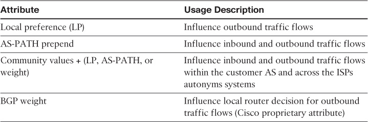
Note
BGP community values technically can be seen like a “route tag,” which can be contained within the one AS or be propagated across multiple autonyms systems to be used as a “matching value” to influence BGP path selection. For instance, one of the common scenarios with global ISPs is that each ISP can share the standard BGP community values used with its customers to distinguish IP prefixes based on its geographic location (for example, by region or continent). This offers enterprises the flexibility to match the relevant community value that represents a certain geographic location and associate it with a BGP policy such as AS-PATH prepending to achieve a certain goal. For example, an enterprise may want all traffic going to IP prefixes within Europe (outbound) to use Internet link 1, while all other traffic should use the second link. As illustrated in Figure 4-33, BGP community values can simplify achieving this goal to a large extent in a more dynamic manner.
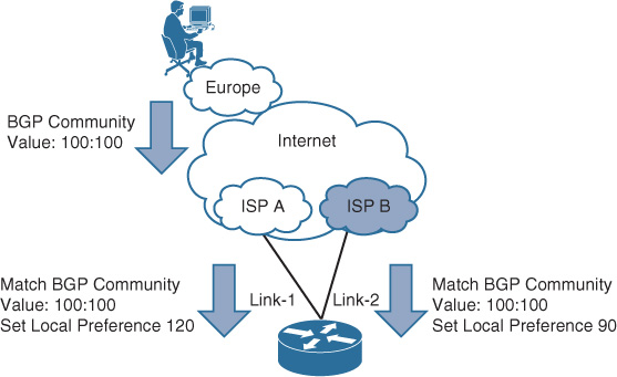
Common Internet Multihoming Traffic Engineering Techniques over BGP
This section covers the primary traffic engineering models and techniques that you can use with multihomed Internet connectivity over BGP.
Note
Throughout this section, ingress always refers to the inbound direction toward the enterprise, and egress refers to the outbound direction toward the SP cloud.
Scenario 1: Active-Standby
This design scenario (any of the connectivity models depicted in Figure 4-34) is typically based on using one active link for both inbound and outbound traffic, with a second link used as a backup. This design scenario is the simplest design option and is commonly used in situations where the backup link is a low-speed link and is only required to survive during any outage of the primary link.
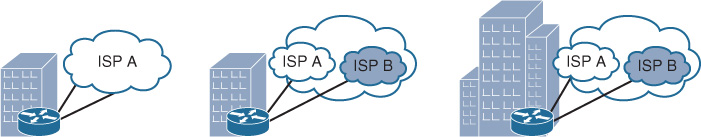
Figure 4-35 shows an active-standby scenario where ISP A must be used as the primary and active path for both ingress and egress traffic flows.
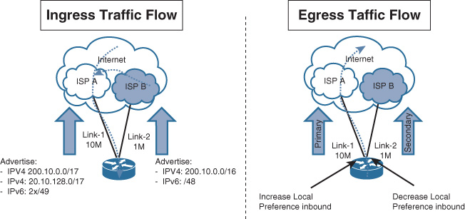
Table 4-14 outlines a possible solution for this scenario.
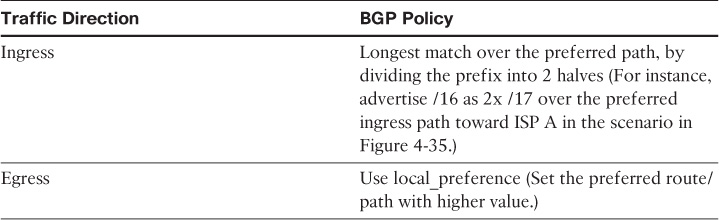
Although AS-PATH prepending is one of the most common and obvious techniques that you can use here in this scenario to influence ingress traffic, ISPs usually allocate a higher local_preference value to prefixes learned by their customers than the ones learned through other peering ISPs. In other words, even though the prefix 200.10.0./16 is advertised to both ISP A and B with AS-PATH prepending applied toward ISP B, ISP B’s customers will always use the path over ISP B because it will be assigned higher local_preference (within ISP B cloud) than the one learned via ISP A, when traffic is passing through ISP B. This means that the targeted goal will not be achieve optimally in this case because any traffic flow coming from any of ISP B’s customers will use the low-bandwidth link (link 2 in this case) to reach 200.10.0.0/16. Therefore, by dividing the /16 network into two /17s and advertising it over ISP A, if there is a customer of ISP B that wants to reach your prefix (one of the 2 x /17s advertised by ISP A), ISP B will never get to the /16 sent over ISP B link because the longer match over ISP A will always win in this case, as illustrated in Figure 4-35.
Note
This behavior (where ISPs allocate a higher local_preference value to prefixes advertised within their cloud) is altered sometimes when the ISP enables their customers to control what BGP attribute and value they need to assign their prefixes when injected into the ISP cloud. This is normally achieved by using standard BGP community values to influence traffic routing within the ISP cloud (most commonly to change AS-PATH or local_preference values within the ISP cloud). For example, in the scenario illustrated in Figure 4-36, if you assign a BGP community value 300:110 to prefix 200.10.0.0/16 toward ISP A (AS 300), its BGP local_preference value within the SP cloud will be set to 110, which will be given preference across this SP cloud and its directly connected customers. Similarly, if you assign a BGP community value 500:70 to prefix 200.10.0.0/16 toward ISP B (AS 500), along with BGP AS-PATH prepending 3 x ASN, (100 100 100), this will make this prefix carry a low local_preference value within AS 500 (assuming, 70 is less than the common default BGP local_preference “100”). In addition, it will be seen (by AS 500) as a longer AS path (100 100 100) compared to the prefix learned via ISP A (AS 300). Technically, the prefix 200.10.0.0/16 within AS 500 will be seen as follows:
Via AS 100: Local_preference = 70, AS-PATH = (100 100 100)
Via AS 300: Local_preference = 100, AS-PATH= (300 100) (preferred path)
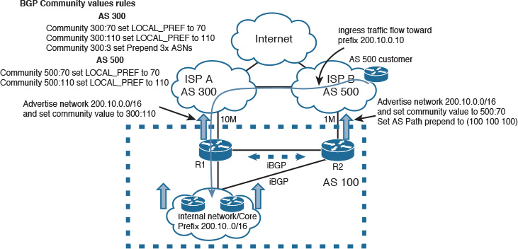
With this approach, network designers can achieve a true and optimal active-standby Internet connectivity model. However, two limitations apply to this approach. First, not every ISP provides this flexibility to their clients. Second, when customers are multihoming to different ISPs, the advertised prefixes must be PI to avoid having the upstream ISP aggregate the advertised prefix and break the entire design. For instance, if ISP A advertises the prefix 200.10.0/16 toward ISP B as 200.0.0.0/8, the path via R2 over ISP B will be always preferred by ISP B customers (longest match) regardless of which BGP attribute has been used.
Scenario 2: Equal and Unequal Load Sharing
These types of design scenarios are commonly used either when there are two Internet links with the same bandwidth value and traffic needs to be distributed evenly across the two links to increase the overall bandwidth and reduce traffic congestion (equal load sharing) or when the Internet links have a different amount of bandwidth where traffic can be distributed in a weighted manner. Ideally, the link with higher bandwidth should handle more traffic than the link with lower bandwidth, as summarized in Figure 4-37.
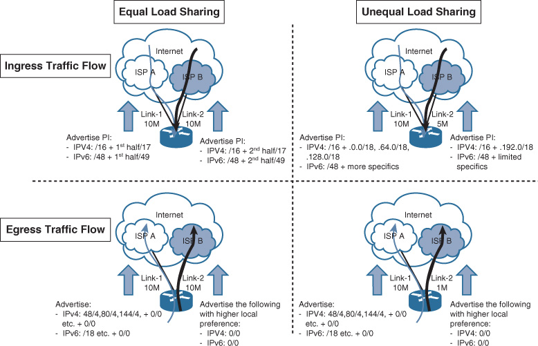
Table 4-15 shows a typical solution.
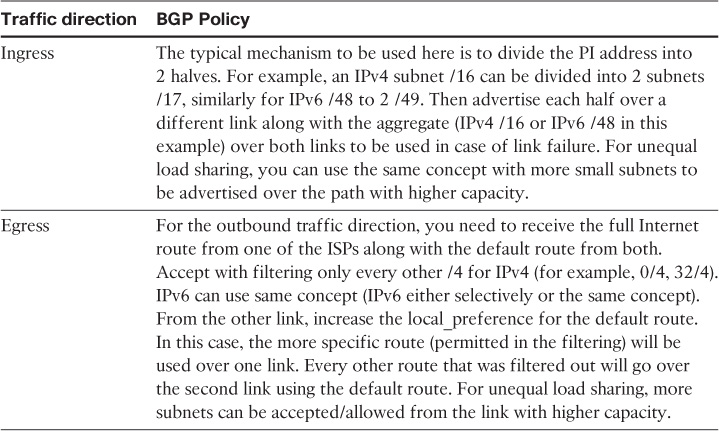
ISPs usually deploy route filtering policies with their customers and with other peering ISPs, where only certain subnet lengths are accepted, to avoid propagating a large number of small network such as v4/24 or v6/ 64. However, the subnets presented in this section are hypothetical to simplify the explanation of the discussed points.4
4. http://www.space.net/~gert/RIPE/ipv6-filters.html
Although the typical mechanisms used to influence path selection equally (to certain extent) are the ones described in Table 4-15, this cannot guarantee fair or equal load distribution across both links (because traffic load cannot be measured based only on its network or subnet size). For instance, if a /24 subnet divided into two halves (.0/25 and .128/25), advertising each half (/25) over two separate Internet links will (in theory) provide equal load distribution across both Internet links in the inbound direction. In fact, what is hypothetically correct is not always practically achievable; the reason why is because if there are a few hosts such as an FTP or web server as part of the subnet (0/25), with high traffic volume destined to these servers, the link advertising (0/25) will be used more than the second Internet link. This same concept applies to the outbound traffic direction. In other words, achieving true equal load distribution must not be derived only by IP subletting (dividing and advertising the available IP range equally across the available links). Instead, it must be based on actual service utilization reports. Alternatively, you can use a specialized load-balancing appliance that that can distribute traffic flow equally based on real-time link utilization.
Similarly, if unequal load sharing is required (for example, 70/30 load distribution, which means 70 percent of traffic should use the link with higher bandwidth and 30 percent should use the other link with lower bandwidth), the same principle and concerns discussed earlier with regard to equal load sharing apply here. In other words, proper planning and a study of utilization reports must be performed before designing and applying BGP policies to influence which network or host should be reachable over which link. Also, the same applies to outbound traffic. (What are the most targeted services in terms of traffic volume and number of traffic flows, such as cloud-hosted applications like Cisco Webex?) After these facts are identified, network designers can provide a more practical multihoming with the desired proportional load distribution model (whether it is equal or unequal load distribution).
Note
Cisco Performance Routing (PfRv3) technology can achieve an advanced level of traffic load distribution based on different criteria and real-time link utilization.5
5. http://docwiki.cisco.com/wiki/PfR:Technology_Overview
Scenario 3: Equal and Unequal Load Sharing Using Two Edge Routers
The design techniques described in the preceding scenarios all apply to this scenario for the ingress traffic flow direction. However, the egress traffic flow direction depends on the LAN side design behind the routers:
![]() Using a firewall with a Layer 2 switch between the firewall and routers: Use multiple groups of Hot Standby Routing Protocol (HSRP) or Virtual Router Redundancy Protocol (VRRP) for load sharing on the routers’ side.
Using a firewall with a Layer 2 switch between the firewall and routers: Use multiple groups of Hot Standby Routing Protocol (HSRP) or Virtual Router Redundancy Protocol (VRRP) for load sharing on the routers’ side.
![]() Using Layer 3 network node, such as a switch connecting directly to the edge routers: You can use IGP with ECMP in this case.
Using Layer 3 network node, such as a switch connecting directly to the edge routers: You can use IGP with ECMP in this case.
Note
In both cases, you need to make sure that there is a link between the two Internet edge routers (physical or tunnel) with internal BGP (iBGP) peering over this link, to avoid traffic black-holing in some failure scenarios.
Asymmetrical Routing with Multihoming (Issue and Solution)
The scenario depicted in Figure 4-38 demonstrates a typical design scenario with a potential for asymmetrical routing. This scenario is applicable to two sites or data centers with a direct (backdoor) link, along with a layer of firewalling behind the Internet edge routers. In addition, these firewalls are site specific, where no state information is exchanged between the firewalls of each site. In addition, both sites are advertising the same address range toward the Internet (PI or PA) range. Therefore, a possibility exists that return traffic (of outbound traffic) originated from site 1 going to the Internet using the local Internet link will come back over the site 2 Internet link. The major issue here is that the firewall of site 2 has no “state information” about this session. Therefore, the firewall will simply block this traffic. This can be a serious issue if the design did not consider how the network design will handle situations like this, especially during failure scenarios.
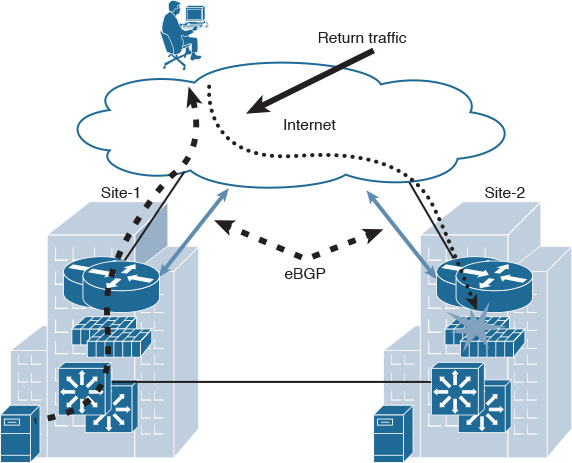
To optimize this design to overcome this undesirable behavior, network designers need to consider the following:
![]() Control plane peering between edge routers in each site: The first important point here is to make sure that both Internet edge routers are connected directly and use iBGP peering between them. This link can be physical or over a tunnel interface, such as a GRE tunnel. A network designer can optimize this design and mitigate its impact by adding this link along with associated BGP policies (make site 1 internal prefixes more preferred over the site 1 Internet link), which will help to avoid the blocking by the site 2 firewall.
Control plane peering between edge routers in each site: The first important point here is to make sure that both Internet edge routers are connected directly and use iBGP peering between them. This link can be physical or over a tunnel interface, such as a GRE tunnel. A network designer can optimize this design and mitigate its impact by adding this link along with associated BGP policies (make site 1 internal prefixes more preferred over the site 1 Internet link), which will help to avoid the blocking by the site 2 firewall.
![]() Organized IP addressing advertisement: To make the preceding point work smoothly, we need to make sure that each site is advertising its own route prefixes as more specific (longest match principle), in addition to the aggregate of the entire PI subnet, as discussed earlier. For example, /16 might be divided to two /17s per site. (You can use the same concept with IPv6.).
Organized IP addressing advertisement: To make the preceding point work smoothly, we need to make sure that each site is advertising its own route prefixes as more specific (longest match principle), in addition to the aggregate of the entire PI subnet, as discussed earlier. For example, /16 might be divided to two /17s per site. (You can use the same concept with IPv6.).
![]() NAT consideration: The other point to be noted here is that if these prefixes are NATed by the edge firewalls, one of the common and proven ways to deal with this type of scenario is by forming direct route peering between the distribution/core layer nodes and the Internet edge routers. Consequently, the edge firewalls can perform NAT for traffic passing through them (as long as the two earlier considerations mentioned in this list are in place).
NAT consideration: The other point to be noted here is that if these prefixes are NATed by the edge firewalls, one of the common and proven ways to deal with this type of scenario is by forming direct route peering between the distribution/core layer nodes and the Internet edge routers. Consequently, the edge firewalls can perform NAT for traffic passing through them (as long as the two earlier considerations mentioned in this list are in place).
For instance, in Figure 4-39 the Internet edge distribution is peering with the Internet edge router using multihop eBGP with private AS and advertising the PI prefixes over BGP (using static routes with a BGP network statement to advertise the routes). The firewall is using a default route toward the Internet edge router, along with NAT.
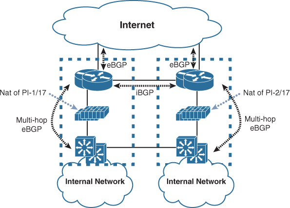
By incorporating the design recommendations to optimize the preceding scenario, a network designer can make the design more agile in its response to failures. For example, in the topology in Figure 4-39, if the link between site 1 and the Internet were to go down for some reason, traffic destined for site 1 prefixes (part of 1st half of the /17) would typically go to the site 2 Internet link (because we advertise the full /16 from both sites). Then traffic would traverse the intersites link to reach site 1. As a result, this design will eliminate the firewall blocking issue, even after an Internet link failure event, as illustrated in Figure 4-40.
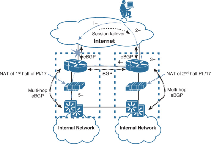
Summary
Today’s enterprise businesses, in particular multinational and global organizations, primarily rely on technology services and applications to achieve their business goals. Therefore, the enterprise edge module (both WAN and Internet) is one of the most vital and critical modules within the modern modular enterprise architecture. It represents the gateway of the enterprise network to the other remote sites, locations, business partners, and the Internet. Therefore, network designers must consider designs that can provide a common resource access experience to the remote sites and users, whether over the WAN or the Internet, without compromising any of the enterprise security requirements, such as end-to-end path separation between certain user groups. In addition, optimizing Internet edge design with business-driven multihoming designs can play a vital role in enhancing the overall Internet edge performance and design flexibility and can maximize the total ROI of the available links. Last but not least, overlay integration at the enterprise edge in today’s networks can offer enterprises flexible and cost-effective WAN and remote-access connectivity, even considering the additional layer of control plane and design complexity that may be introduced into the overall enterprise architecture.