Chapter 3
Autonomous Deployments
A lot of WLAN deployments still use autonomous/standalone access points (AP) or bridges. In fact, the Internet of Things is keeping the workgroup bridge (WGB) very busy in different types of environments. So yes, wireless CCIEs still need to deal with scenarios using autonomous WLAN devices. Because WGBs are specialized devices, CCIEs are usually expected to know “at least something” and have enough expertise to deal with some devices/topologies that many other WLAN engineers have never worked with.
The Cisco IOS autonomous WLAN devices (sometimes called aIOS, for autonomous IOS) encompass multiple models of hardware indoor and outdoor APs (or bridges) that could be used as lightweight/CAPWAP APs managed by WLCs, but where you can install instead a Cisco IOS Autonomous AP image, so you can manage the unit as a standalone device, just like many other Cisco IOS devices (same core OS and CLI look and feel that you get in the well-known Cisco IOS routers and switches).
Although autonomous APs can be used in many roles, their main use case has become to perform wireless bridge links, which specifically translates to the following deployment models:
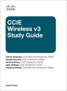
Point-to-Point Bridging: One device acting as the root bridge and another device acting as the non-root bridge, simply extending a Layer 2 Ethernet link over wireless.
Point-to-Multipoint Bridging: One device acting as the root bridge and two or more devices acting as non-root bridges. The root bridge is at a central location (normally the main LAN), and all the non-root bridges establish point-to-point Layer 2 links with the root to wirelessly provide an uplink for the remote locations behind them.
Workgroup Bridge (WGB) deployments: The WGB connects to 802.11 access points acting in their regular root AP role for Wi-Fi clients (and can also connect to root bridges). WGB connects to the root as a wireless “regular” client or “infrastructure” client and can host and relay traffic to and from one or more wired clients. The wired device(s) or network behind the WGB connects to the main network infrastructure over the wireless link between the WGB and its root (AP, bridge, or even WLC port).
The purpose of this chapter is to give you the core knowledge (and main tips) required to deploy, configure, and troubleshoot Cisco IOS Autonomous WLAN devices implemented in the deployment models described previously.
The Role in the Deployment
As previously introduced, three main deployment models will be discussed in this chapter, and for each model, the autonomous WLAN device plays a different role based on its position (and purpose) in the network. This role is specifically configured in one of its radio interfaces, as you can see in Example 3-1.
Example 3-1 Radio Interface station-role ? Command Output
aIOSAP(config)# interface dot11Radio 1
aIOSAP(config-if)# station-role ?
  non-root          Non-root (bridge)
  root              Root access point or bridge
  workgroup-bridge  Workgroup Bridge
Depending on which radio band is used for this wireless link, you will configure the 2.4 GHz radio or the 5 GHz radio (interface Dot11Radio 0 or Dot11Radio 1, respectively). The remaining radio interface is not used, so the recommendation is to shut it down (mainly because using the remaining radio with the same role or other roles is not supported or recommended).
Before getting further into the details of these configurations, it is important to remember that wireless bridge links are not clearly defined by the 802.11 standard. The standard mainly defines communications between stations (STA), one of which could act as an access point. In 802.11, the AP is the only one that can “bridge” traffic between the wireless network and the wired infrastructure, from one MAC address (could be a client STA) to another MAC address (for example, the client’s default gateway). Hence, vendors deploying WGBs and bridges implement proprietary features that make the client bridge act and be treated as an “infrastructure” device (more on this later in the chapter), which lets them bridge traffic similar to an AP but acting as a client associated to a root. Transmissions also take advantage of elements available in 802.11 frames’ headers: They support up to 4 MAC addresses, known as Source Address (SA), Transmitter Address (TA), Receiver Address (RA), and Destination Address (DA). For example, the 802.11 header has the following fields available for addresses:
Address 1 = Receiver Address (RA)
Address 2 = Transmitter Address (TA)
Address 3 = Destination Address (DA)
Address 4 = Source Address (SA)
In a standard 802.11/Wi-Fi communication, only 3 MAC addresses are used in those headers: one for the original source, one for the final destination, and the MAC of the AP where the client is associated (known as the BSSID). So if a wireless client is transmitting a frame to the default gateway, the transmitter address (TA) is the client (which is also the source address, SA, because the original frame source is the same as the device transmitting the frame over the air), the destination address (DA) is the final destination (the gateway), and the receiver address (RA) is the AP BSSID (which is like a Layer 2 bridge receiving the frame over the air to bridge it to the true final destination). Based on the available address fields in the 802.11 header, this example will be something like the following:
Address 1 = Receiver Address (RA) = AP BSSID
Address 2 = Transmitter Address (TA) = Client
Address 3 = Destination Address (DA) = Gateway
Address 4 = Source Address (SA) = Not used, because it is the same already in Address 2
If the default gateway is now transmitting back to the wireless client, the frame looks as follows over the air from the AP to the client: the source address (SA) is the gateway, the transmitter address (TA) is the AP, and the receiver/destination addresses (RA and DA) are a single MAC (wireless client). In this case, the frame header will be
Address 1 = Receiver Address (RA) = Client
Address 2 = Transmitter Address (TA) = AP BSSID
Address 3 = Destination Address (DA) = Not used, because it is the same already in Address 1
Address 4 = Source Address (SA) = Gateway
When doing the so-called “wireless bridge links” based on 802.11 frames, not only is the root (AP or bridge) allowing a wireless client to send frames on behalf of other MAC addresses (not allowed by standard 802.11 communications) but the client bridge is also receiving and bridging frames intended for other MAC addresses (the wired clients attached to the WGB or behind the bridge). In these cases, four different MAC addresses are truly used in the four MAC address fields of 802.11 headers:
If a device behind the infrastructure client (non-root or workgroup bridge) is transmitting a frame to the default gateway (final Layer 2 destination address, so gateway = DA), the source address (SA) is the client/MAC behind the client bridge at the origin of that traffic, but the transmitter address (TA—the device transmitting the frame over the air) is the client bridge and the receiver address (RA) is the root BSSID. The header will have the following:
Address 1 = Receiver Address (RA) = Root BSSID
Address 2 = Transmitter Address (TA) = Client Bridge (Non-root or WGB)
Address 3 = Destination Address (DA) = Gateway
Address 4 = Source Address (SA) = Client
If the default gateway is now transmitting back to the device behind the infrastructure client bridge, the frame looks as follows over the air from the root: the source address (SA) is the gateway, the transmitter address (TA) is the root, the receiver address (RA) is the client bridge, and the destination address (DA) is the final destination (the MAC of the device behind the client bridge). In this case, the header is as follows:
Address 1 = Receiver Address (RA) = Client Bridge (Non-root or WGB)
Address 2 = Transmitter Address (TA) = Root BSSID
Address 3 = Destination Address (DA) = Client
Address 4 = Source Address (SA) = Gateway
Root and Non-Root Bridges
Figure 3-1 shows the roles for point-to-point and point-to-multipoint bridging:
This type of wireless bridging is used to extend Layer 2 links; basically an Ethernet link is extended between two devices, but instead of using a large cable you use a wireless bridge link (for example, because you cannot deploy a physical cable between two buildings).
The Cisco autonomous wireless devices (any Cisco AP model that supports autonomous IOS images) act as Layer 2 bridges, similar to switches. You could connect two computers, one to each Ethernet port of a pair of wireless bridges, and once the non-root bridge establishes wireless association with the root bridge, the computers would be able to communicate (again, just like connecting an Ethernet cable between them).
Hence, you could also connect two routers’ Layer 3 interfaces to the Ethernet ports of the bridges (one behind the root and another behind the non-root), and the routers will communicate with each other as if they were connected over a cable; the wireless bridge link is totally transparent to them. The router interfaces configuration would be identical, irrespective of the physical link between them (cable or wireless).
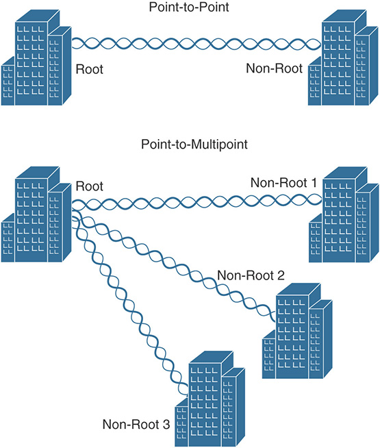
However, the main use of these bridge links is to interconnect two switches to extend the LAN at a location where cabling is not possible (or wireless is just the best option). When this is done, two switchports in access mode can be connected by the wireless bridge link to transport traffic for a single VLAN between the switches. Even better, two switchports in 802.1Q trunk mode can be connected so that traffic from more than one VLAN can be transported over the wireless link. In this case, the VLANs to be allowed/used between the switches need to be configured in the wireless bridges. Figure 3-2 illustrates the possibilities when bridging between switches.
To achieve such design or similar (such as one where all VLANs 5–10 are supported in all switches), you need to make sure that the LAN infrastructure and switches involved are properly configured to allow/use the VLANs you want, with proper trunks (including the switchports where the bridges directly connect) and all the VLANs with working connectivity. After you insert the wireless bridges between switches, you just need to have the required VLANs configured on the bridges; this is done by using subinterfaces with bridge-groups.
Subinterfaces are used to segregate VLANs just like in other Cisco IOS devices. The reason behind using bridge-groups is that the IOS autonomous APs/bridges are Layer 2 devices (so they don’t route) that use these bridge-groups to bridge and convert traffic between two physical interfaces working with different Layer 2 protocols. They bridge 802.11 wireless frames from a radio interface to 802.3 frames in the Ethernet interface, and vice versa. They can also bridge traffic between radio interfaces.
By default, these devices have one virtual interface (called the bridge virtual interface, or BVI1) linking all those physical interfaces. This BVI1 is the actual interface “mastering” bridge-group 1, bridging Ethernet and radio(s) together via bridge-group 1, and is the only Layer 3 interface that should have an IP address. You use the BVI1 IP address to connect to the bridge over an IP network (for management purposes, for example). This BVI1 will never mark traffic with a VLAN ID (no 802.1Q tag). Therefore, the BVI subnet is always considered the 802.1Q native VLAN when configuring multiple VLANs on the device. This means that the AP/bridge will always have its IP address, manually configured or obtained via DHCP, assigned to the BVI1 interface and located within the subnet of the native/untagged VLAN configured at the Ethernet port where the bridge is connected.
Example 3-2 is a basic bridge-group 1 setup, which is enough to bridge those interfaces and carry traffic for a single VLAN (all within the same subnet mastered by BVI1 and without VLAN tagging).
Example 3-2 Bridge-Group 1 Setup Without VLANs
Bridge(config)# interface Dot11Radio0
Bridge(config-if)# bridge-group 1
Bridge(config-if)# interface Dot11Radio1
Bridge(config-if)# bridge-group 1
Bridge(config-if)# interface GigabitEthernet0
Bridge(config-if)# bridge-group 1
Bridge(config-if)# interface BVI1
Bridge(config-if)# ip address <IP-ADDRESS> (manually configured or DHCP)
Such bridge-group 1 configuration is already by default in these autonomous IOS APs/bridges, and all you normally need to do is to assign the IP address to the BVI1 interface. Some other bridge-group commands/subcommands could come by default (or simply when you enable the bridge-group <1-255> command at each interface), and there is no need to modify those default bridge-group settings, so if you want to try specific bridging behaviors by modifying the defaults, the recommendation is to research for the specific purpose of each command by checking the Cisco IOS bridging/bridge-group documentation (not covered in this book).
Example 3-2 is enough to pass traffic from one site to the other in one VLAN; you do not need to configure any VLAN at the APs/bridges. For example, if you want to pass traffic for VLAN-10, configure the bridges as shown in Example 3-2 and make sure that the APs/bridges at both ends connect to ports configured for that VLAN (no trunk, no tagging). Example 3-3 illustrates a Cisco IOS switchport in access mode configured for this purpose.
Example 3-3 Bridge’s Switchport Configuration for One VLAN
Switch(config)# interface GigabitEthernet 0
Switch(config-if)# description **to the bridge**
Switch(config-if)# switchport mode access
Switch(config-if)# switchport access vlan 10
If the purpose is to connect VLAN 12, for example, then there is nothing to do in the APs/bridges, just connect them to ports in that VLAN (switchport access vlan 12).
Now, if you want to pass traffic over this wireless bridge-link for more than one VLAN, or even just have the APs/bridges in one separate management VLAN and then pass user/data traffic through other VLANs, here is where you need to configure VLANs using subinterfaces with bridge-groups.
You will always have the management VLAN of the APs/bridges (the one where the BVI1 interface will have its IP address) as the native VLAN; this is how the configuration looks if that native VLAN is VLAN 10 at the switchports where the bridges connect. Example 3-4 supposes that you use the 5 GHz interface Dot11Radio1 for the wireless bridge link.
Example 3-4 Bridge-Group 1 Setup with Native VLAN
Bridge(config)# interface Dot11Radio1.10
Bridge(config-if)# encapsulation dot1Q 10 native
Bridge(config-if)# bridge-group 1
Bridge(config-if)# interface GigabitEthernet0.10
Bridge(config-if)# encapsulation dot1Q 10 native
Bridge(config-if)# bridge-group 1
Bridge(config-if)# interface BVI1
Bridge(config-if)# ip address <IP-ADDRESS> (in VLAN-10 subnet range)
In addition, the SSID configuration should have that native VLAN ID assigned, as follows:
Bridge(config)# dot11 ssid Bridges
Bridge(config-ssid)# vlan 10
Then you create other radio and Ethernet subinterfaces with matching bridge-groups bridging them together, using one different bridge-group number per VLAN (anything from 2 to 255), passing all the VLANs you need (only required VLANs as recommended), being the maximum number of VLANs limited by the amount of bridge-groups supported by these devices (255). Regardless of the number of subinterfaces, you will still have only a single BVI interface, with a single IP address (an extra BVI interface should never be configured). Interface BVI1 is enough as the only Layer 3 interface required. Any group other than bridge-group 1 (where the BVI1, native/untagged VLAN resides) is simply a Layer 2 802.1Q tagged VLAN (without BVI interface) that bridges two or more subinterfaces created for that new VLAN. Example 3-5 is the extra configuration required if you were passing two more VLANs (20 and 30) over this link other than the native VLAN 10 previously configured for bridge-group 1 (the first section is the bridges’ configuration, and the second section is the configuration of the switchports where they connect).
Example 3-5 Bridge-Groups for Extra VLANs and Switchports Configuration
Bridge(config)# interface Dot11Radio1.20
Bridge(config-if)# encapsulation dot1Q 20
Bridge(config-if)# bridge-group 20
Bridge(config-if)# interface Dot11Radio1.30
Bridge(config-if)# encapsulation dot1Q 30
Bridge(config-if)# bridge-group 30
Bridge(config-if)# interface GigabitEthernet0.20
Bridge(config-if)# encapsulation dot1Q 20
Bridge(config-if)# bridge-group 20
Bridge(config-if)# interface GigabitEthernet0.30
Bridge(config-if)# encapsulation dot1Q 30
Bridge(config-if)# bridge-group 30
************************
Switch(config)# interface GigabitEthernet 0
Switch(config-if)# description **to the bridge**
Switch(config-if)# switchport mode trunk
Switch(config-if)# switchport trunk native vlan 10
Switch(config-if)# switchport trunk allowed vlan 10,20,30
Note
The bridge-group ID and VLAN ID don’t need to match; it is just recommended for administrative purposes. In fact, because the bridge-group IDs’ limit is 255, if you have VLAN ID 256 or above in your network, you won’t be able to match them (and this is fine).
All that really matters is that you use the proper VLAN ID as configured in the switching LAN infrastructure, that this VLAN is allowed in the trunk where the APs/bridges connect and is tagged with the 802.1Q standard, and that the bridge-group ID matches between the subinterfaces you are trying to bridge together, like in Example 3-5.
The subinterface ID after the dot (for example, GigabitEthernet0.30) doesn’t need to match either—no match between subinterfaces, and no match with VLAN or bridge-group IDs. Using the same number, however, is simpler for administrative purposes.
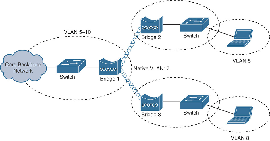
This configuration with the required VLANs is done the same way at the root AP/bridge and the non-root bridge(s). VLAN information is shared over the wireless link between these devices by using the Cisco version of Inter Access Point Protocol (IAPP) developed for proprietary communication between its Cisco WLAN infrastructure devices, and also named Cisco Wireless LAN Context Control Protocol (WLCCP). Figure 3-3 shows a Wireshark capture where two bridges share (over the air) information about the underlying VLANs.
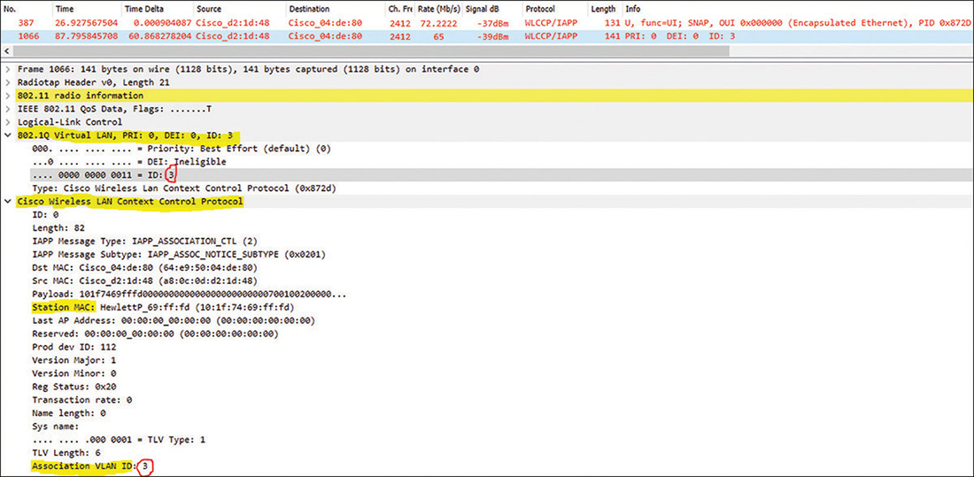
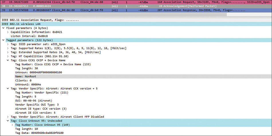
The main difference between the roles root access-point and root bridge is that the root AP is normally used to connect regular 802.11 wireless clients (could also be WGBs), just like lightweight APs, whereas a root bridge is normally used for the designs in Figure 3-1 and will not allow an association attempt from a regular wireless client but only from another Cisco infrastructure wireless device acting as client (like a non-root bridge or a WGB). Root bridge will deny the association to a regular wireless client trying to associate by sending an association response with invalid status code, while sending association responses with successful status code to Cisco infrastructure devices. They recognize each other because, besides Cisco WLCCP, they use Cisco Aironet IE (Information Elements) during the association handshake, as the ones you can see from the packet capture in Figure 3-4, where the association request from a non-root bridge is selected to display the Cisco Information Elements it supports (also known as Cisco Aironet Extensions, or CCX).
When configuring the bridge role at the interface level, you can use the command station-role root bridge to limit the connections to non-root bridges and WGBs only. If you need to allow regular clients to connect on that root bridge you can configure the role as station-role root bridge wireless-clients. Adding the “wireless-clients” keyword configures the root bridge to perform wireless bridge links with Cisco infrastructure clients as explained before, but at the same time also allows regular wireless clients to associate as if the root bridge were a normal 802.11 access point. The same logic is possible with the non-root bridge role. Use the command station-role non-root wireless-clients to configure the non-root bridge as an infrastructure client that will associate with a root bridge and establish the bridge link, but also as an access point to allow associations from regular wireless clients. Just be aware that, in these cases, the same radio is sharing the medium/air-time (and transmit opportunity, performing contention, scanning, etc.) between the two roles, so we can say it is literally sometimes bridging to the other side and sometimes acting as AP for clients.
Workgroup Bridge
Widely used in different designs, the WGB is a versatile wireless client that associates to a root bridge or an AP (Cisco autonomous or lightweight, or even third-party AP) to pass traffic for one or multiple devices connected to its Ethernet interface (connecting those remote devices back to the infrastructure where it wirelessly associates). This is a powerful wireless client that could be static or mobile, using internal antennas or external antennas that better fit the requirements (such as when directional antennas are used to point directly to the root and better align/focus the RF signal for long distances).
Because this WGB role is not defined by the 802.11 standard, its Wi-Fi implementation is proprietary, and this is why you normally can’t connect a WGB (or similar type of device) from a given brand to a root wireless device of a different brand; in the end, the WGB is not really an 802.11 STA normal client. The WGB is truly a proprietary infrastructure client (where its infrastructure behavior is defined by the vendor, in this case, Cisco).
Cisco also developed for its IOS Autonomous WGBs the Universal mode (radio role: station-role workgroup-bridge universal), where the WGB basically acts as a regular 802.11 wireless client (normal client) using the MAC address of the device directly connected to its Ethernet interface as the Wi-Fi and only MAC address that the root AP will see. This limits the capabilities of a WGB but allows normal associations with any 802.11 access point (from any vendor), because it basically follows the standard rules acting as an external Wi-Fi NIC for the device directly connected to its Ethernet interface.
If the radio role is instead station-role workgroup-bridge (not Universal mode but implicit Cisco mode, which is the typical and most used WGB mode), the WGB behaves as an infrastructure client. There, the rules change, and thanks to the capabilities of a Cisco IOS WGB, more options are available. You can now have multiple devices (and hence MAC addresses) behind the WGB by connecting a switch to the WGB’s Ethernet interface. You can connect a router and have several devices/MACs behind that router’s MAC. You can also have the wired clients use different VLANs. You also have the flexibility of treating multicast traffic in different ways (more on this topic later in a separate section), enhancements for mobile environments, and more. Such capabilities are advertised by Cisco Aironet IE and use IAPP/WLCCP packets, just like root/non-root bridges, as explained before; this is the reason why Aironet IE must be configured/enabled in the SSID of the root side when connecting these WGBs, even when connecting them to lightweight APs/WLCs.
In this role (Cisco mode WGB), you often have multiple devices behind the WGB, which are usually connected to a switch that is directly connected to the WGB’s Ethernet port (similar topology as the one in Figure 3-2). By using a switch that supports 802.1Q VLAN tagging and trunks, you could have WGB clients in separate VLANs, and the switchport where the WGB directly connects will be a trunk allowing all those needed VLANs (VLANs should obviously exist and be allowed as well at the root side where the WGB wirelessly associates). You configure VLANs in these Cisco IOS WGBs the same way as explained before in the bridges section, with subinterfaces and bridge-groups, but there are some variants that deserve further explanation:
No VLANs required: If your wired clients are all in the same VLAN, you can keep the default WGB configuration, with the physical interfaces (Ethernet, radio) linked by bridge-group 1. Your BVI1 interface will also have an IP address in the subnet associated to that VLAN. The WGB and its clients will then all be in the VLAN assigned to the SSID on the root bridge or AP.
VLANs when connecting to an IOS Autonomous Root: If your wired clients are in different VLANs and the WGB connects to an autonomous AP, configure the WGB with VLANs as explained previously in the bridges section; configure in the WGB the VLANs required by using subinterfaces and bridge-groups, leaving the WGB management (BVI1) interface in the native VLAN (and assigning this VLAN ID to the SSID configuration). The autonomous root (can be root AP or root bridge) should have at least the same VLANs configured, but the root could also have other extra VLANs configured that could be used for other SSIDs (if root AP) or for other bridge links, and not necessarily for that specific WGB link.
VLANs when connecting to an AireOS lightweight AP/WLC: If your wired clients are in different VLANs and the WGB associates to an AP connected to a WLC, configure the WGB with the needed VLANs by using subinterfaces and bridge-groups as shown previously. You also need to do the following:
Configure the WGB with the global config command workgroup-bridge unified-vlan-client so the WGB can advertise to the WLC the VLANs to be used for the wired clients (the WGB native VLAN/BVI1 interface will be in the VLAN assigned by the SSID).
Configure the WLC with the command config wgb vlan enable so the controller can support the VLANs advertised by the WGB.
Just one extra VLAN for clients behind the WGB not using VLAN tagging: If you want to have the WGB (BVI1) IP address in its own management subnet/VLAN and put all the devices behind in a separate VLAN by connecting to the WGB’s Ethernet port a hub or switch that is not capable of doing 802.1Q tagging/trunk (or even just directly connecting to the WGB a PC or client device that can’t do VLAN tagging), you do something similar by configuring the VLANs required using subinterfaces and bridge-groups, leaving the WGB management (BVI1) interface in the native VLAN (and assigning this VLAN ID to the SSID configuration). The root side should allow both VLANs, and its SSID VLAN should be the WGB’s native VLAN (the one where you want the WGB to get its IP address, just like in the previous scenarios). Then, all you have to do is specify the client VLAN at the WGB with the command workgroup-bridge client-vlan <VLAN-ID>, and with this, the WGB will use that one VLAN only for its Ethernet interface without tagging (leaving all the devices behind in this VLAN), but 802.1Q tagging with this VLAN ID over the air (radio interface) to let the root side know that the WGB clients should belong to that VLAN.
Note
When connecting the WGB to a Cisco IOS autonomous root AP, the radio interface command infrastructure-client is required at the root to support VLANs with the WGBs connected to it. This command/feature will allow the autonomous root to treat (and trust) a Cisco mode WGB as an infrastructure client, because it will speak IAPP/WLCCP and 802.1Q VLAN tagging only with trusted infrastructure clients (not with devices that the root AP considers normal clients).
Note that this command is required only in the root AP side, not the WGB side; the WGB simply needs to be in the implicit Cisco mode (not universal) and have the VLANs properly configured.
You can see the devices learned by the WGBs (similar for root and non-root bridges) and their assigned bridge-group (hence VLAN) by using the command show bridge. Example 3-6 shows an output of this command.
Example 3-6 show bridge Command Output
WGB# show bridge
Total of 300 station blocks, 294 free
Codes: P - permanent, S - self

Bridge Group 1:
    Address       Action   Interface       Age   RX count   TX count
34db.fd22.f1d0   forward   Vi0.2             0          0          0
f09e.6342.32f7   forward   Vi0.2             0          1          0

Bridge Group 3:
101f.7469.fffd   forward   Gi0.3             0       1618       1065
f09e.6342.32e7   forward   Vi0.3             0       1066       1292
As you can see, these IOS autonomous WLAN devices have their bridge table populated with all the MAC addresses that they have learned (like a switch MAC-address table), segregated by bridge-groups, based on the VLAN where the device is located, along with the interface each MAC address was learned from. You can see if the address was learned over the GigabitEthernet interface (like the entry highlighted in Example 3-6, which is for a wired client behind the WGB, heard and classified through the subinterface known as Gi0.3) or over a radio interface via the wireless link (such as all the other MAC addresses in the output, which are learned by this WGB in the example via the wireless/radio interfaces identified as Vi—for Virtual, classified based on their VLAN/subinterface/bridge-group. These are MAC addresses coming from the root side; they can be other wired devices behind the root or wireless clients associated to the root). As can be concluded, two MAC addresses were learned over the native VLAN (Bridge Group 1) and two other MAC addresses were learned over the VLAN/subinterfaces created for Bridge Group 3.
Something important to consider with WGBs and the bridge table they create is the behavior of the wired devices behind the WGB; specifically, the so-called passive client behavior. If a wired client behind the WGB doesn’t transmit traffic for an extended period of time, the WGB will remove the device from its bridge table (or if the wired client never starts some traffic when coming up for the first time or after getting deleted, the WGB will never populate its bridge table with the MAC address of that wired client). Consequently, traffic destined to a wired client (behind the WGB) that is not in the WGB’s bridge table will be lost.
Hence, to avoid traffic loss for such passive wired devices, you can do the following:
Increase the aging-out timer: This will prevent early deletions from the bridge table by configuring the aging time in seconds (between 10 and 1,000,000 seconds), which is the amount of time the WGB will wait before removing a client that has been idle/inactive (from the last moment it sent traffic) in a specific bridge-group. This is mainly helpful for devices that are not completely passive but are not very active or that just send some traffic in between long periods of time. The global configuration mode command to modify this timer (in seconds) is bridge <1-255> aging-time <10-1000000>.
Add static/manual MAC address entries to the bridge table: By doing this, the devices’ MAC addresses configured manually will always be present in the bridge table, without aging (so will not get deleted). Just use the global configuration mode command bridge <1-255> address H.H.H forward gigabitEthernet 0.
Mobile WGB
Used in a mobile deployment—for example, in transportation (such as connecting trains to Wi-Fi in subways) or health care (medical equipment carts that use the WGB as their Wi-Fi NIC to be always connected anywhere there is WLAN coverage), the WGB needs to meet requirements that are normally expected from a regular mobile client; that is, make appropriate decisions about when and where to roam, perform Fast-Secure roaming if EAP authentication is used, implement smart scanning, and others. The Cisco IOS autonomous WGBs let you set up some settings that help with such mobile requirements.
For Fast-Secure roaming (methods used to perform fast roaming when secure Wi-Fi authentication is used, by avoiding the reauthentication when moving between APs using caching techniques), as of this writing in early 2018, Cisco WGBs only support CCKM as a Fast-Secure roaming method, which means that the infrastructure WLAN/SSID where the WGB connects should also be configured to allow CCKM for this Fast-Secure roaming to occur. All you need in the WGB setup is the following SSID configuration command option for the key management method, and the rest of the SSID configuration is the same as for WPA/WPA2 enterprise (more about security later in this chapter): authentication key-management cckm.
By default, when looking for the best root (for initial association or to roam), the WGB scans all country channels supported in its regulatory domain, so you can imagine that it takes some time for the WGB to finish scanning all channels (a lot more channels exist in the 5 GHz band than in 2.4 GHz, and if there’s a DFS channel, scanning takes even longer because it must be done via passive scanning—waiting to hear beacons instead of actively probing). So to accelerate roaming, it is recommended to configure the WGB to scan only the channels that are used by the WLAN infrastructure; for example, if you’re using the 2.4 GHz band and the infrastructure root APs are configured only for channels 1, 6, and 11 (as they should), then configure the WGB radio interface command mobile station scan 1 6 11 to scan only those three channels.
But when is the WGB going to start the roaming? Because no specific 802.11 rules force/trigger a Wi-Fi roaming, each client vendor relies on multiple factors to trigger a roaming decision, such as current root beacon loss, current signal quality going down (and if available, other roots around heard with better signal quality), shifting down to low data rate, packet retries and loss, and others. WGBs work with most of the typical triggers for a roaming event, but the following three can be manipulated:
Packet retries: By default, if the WGB (or non-root bridge) reaches the maximum packet retries because it never received an ACK for a data frame that is trying to transmit to the root parent, it will start roaming and disassociate from the current root. One single packet that was never confirmed to be received by the root will trigger this event, so you can not only manipulate the amount of retries required to take this decision but can tell the WGB to better drop the actual frame that has not been ACK (give up the transmission) instead of deliberately giving up to current association. This behavior is modified with the WGB (or non-root bridge) radio interface command packet retries <number of max retries> [drop].
RSSI monitoring: With the radio interface command mobile station period <seconds> threshold <RSSI>, WGBs can proactively scan their current root signal quality every “period <seconds>”, and if the signal perceived at that time is below the “threshold <RSSI>” value (configured as positive integer, but truly meaning a normal −dBm measured signal), then roaming will be triggered. Ideally, you should do enough testing in the environment (roaming between APs) to confirm what the best values are for your deployment, because this could cause the WGB to never roam when you expect it or to roam too frequently (which could be too aggressive). In general terms, the time period value should not be lower than what it takes for the WGB to complete full association and secure authentication to avoid a roaming loop, so 2–4 seconds is recommended, depending on the setup/environment. The threshold RSSI value highly depends on the design and the expected signal quality at the root APs’ cell edges; that is, if the WLAN infrastructure is designed for the APs to provide coverage at a minimum of −70 dBm, you would normally expect the clients to roam to a nearby AP, perceived with better signal, when they reach their current cell edge (−70 dBm). Hence, this should be the RSSI value configured in the command for the WGB to trigger roaming to the next AP by the time it reaches the current edge (assuming the design is good enough for the WGB to find another good candidate root parent with a better signal; otherwise, this will trigger constant roaming in a very aggressive behavior, without truly finding another good option to roam and stay). The cells’ edge RSSI is supposed to be derived based on your wireless clients’ applications/services requirements, which is normally also tied up to the minimum data-rate speed required to support the app/service. Therefore, you should not only consider the minimum RSSI of the connection but also the minimum data rate, and in fact, using this command can also trigger a “roaming by data-rate change,” even if the new data rate is still good enough (which is too aggressive). This is why the RSSI monitoring feature should always be used together with the following feature, minimum data rate.
Minimum Data Rate: Used together with the previous feature/command, the radio interface command mobile station minimum-rate <data-rate> will prevent the WGB from triggering a roaming event unless the current connection has dropped below the configured data rate. If the current connection data rate is good enough to support the clients’ applications/services, why roam to another AP and go over another association/authentication handshake that could disrupt current services? Remember that the data rate will definitely drop if the current signal quality—RSSI and SNR—drops to a level where the current data rate can’t be sustained. After the connection data rate drops below the minimum required for your design, and the current RSSI is below your cell edge, it is a good time to trigger roaming, and this will happen in a smart and controlled way thanks to these last two features/commands.
Workgroup Bridges for High-Speed Roaming
In some deployments, the WGB could be moving (and hence roaming) at high speeds, much faster than regular mobile clients; for example, when the WGB is installed in high-speed rail coaches to provide them with connectivity. As the train moves, the WGB in the coach roams from one root AP to the next one installed along the railway track.
In such scenarios, train speed could be about 100 km/h, with the root APs placed about 200–300 meters apart along the track. The only way for the WGB to support roaming between those APs while moving at such high speeds is by configuring some required settings for high-speed roaming in the entire WLAN deployment.
First, as of this writing in early 2018, this is supported only by Cisco Aironet 3600 and 3700 series APs acting as WGBs, and they must associate to a WLAN infrastructure that supports 802.11v BSS Transition. So if the root APs along the railway track are lightweight APs managed by a WLC, the WLAN/SSID at the controller must have 802.11v BSS Transition enabled. This allows for the WGB to receive (and request) neighbor list information, which is provided by the current root AP, and helps the WGB to identify possible next root APs to roam to (and their channels). Knowing their channels helps the WGB perform a more efficient and faster scan when roaming.
Then, using the radio interface drssi commands, you can get the 3600/3700 WGBs to perform high-speed roaming. For example, using the radio interface command drssi roaming threshold 67 period 1 packet 20, you can do the following:
When the current root AP is perceived with an RSSI level below the threshold configured (which represents the real RSSI of a connection, so value 67 is truly −67 dBm), the WGB will start scanning to roam to a better root AP. It is recommended to set this threshold about 2 to 3 dBm below the average RSSI level in the middle point between two APs on the track.
The period value controls how often the WGB decides to evaluate the quality of the link with the current parent. It is the minimum time (in seconds) between scans. So if the train is moving very fast, you want the evaluation to happen more frequently (short period value), but if the speed is slow, it is better to avoid frequent scans (where WGB needs to go off channel constantly) by configuring a longer period.
The packet value is the number of sample data packets from the current root AP that the WGB uses to keep track of the current link quality. The WGB maintains an RSSI average from the last data packets (last 20 per our sample command drssi roaming threshold 67 period 1 packet 20), and if this average RSSI falls below the RSSI threshold configured in this command, the WGB will initiate a roam. Hence, if the train is moving very fast, the recommendation is to use a small number of packet samples to calculate this average RSSI.
This specific configuration, drssi roaming threshold 67 period 1 packet 20, works well up to a speed of 100 km/h; this configuration has been tested and is recommended under those circumstances. Depending on the speed, design, and requirements, you will need to calculate and fully test the appropriate values for the specific environment.
The other helpful radio interface drssi command is drssi scan-only current-neighbor-list. With this configured, the WGB scans only the neighbors list that is received (thanks to 802.11v BSS) from the last associated AP. You can also disable this command (no drssi scan-only current-neighbor-list) so that the WGB ages out the neighbors list gradually (the age-out factor is reduced by 1 for every roam).
Cisco IOS Autonomous Security
Several security settings and protocols are supported in the Cisco IOS autonomous APs, bridges, and WGBs. Some are implemented by default, and others can be modified or depend on the configuration/setup/design. Some of them are ported from the core of Cisco IOS and are not even wireless related but are security features that could apply to multiple Cisco IOS networking devices, like routers and switches (for example, IOS device’s SSH and crypto implementations).
This section of the book covers only the most specific wireless security settings applicable to the wireless autonomous deployments covered so far, which are based on the CCIE blueprint.
Layer 2 Wireless Security
The Cisco IOS autonomous WLAN devices support all the Layer 2 security methods defined by the 802.11 standard as of the writing of this book, from open system authentication (without encryption and with static WEP or even dynamic WEP using 802.1X/EAP) to shared key authentication, as well as all flavors of WPA (versions 1 and 2) as summarized in Table 3-1.
Table 3-1 WPA/WPA2 Layer 2 Security Frameworks
|
WPA (or WPAv1) |
WPA2 (or WPAv2) |
Personal |
Authentication: PSK (Preshared Key) Encryption: TKIP |
Authentication: PSK (Preshared Key) Encryption: AES-CCMP |
Enterprise |
Authentication: 802.1X/EAP Encryption: TKIP |
Authentication: 802.1X/EAP Encryption: AES-CCMP |
You can even do MAC address authentication (against a local list or against a RADIUS server), which is not really a security authentication method defined by the standard (there’s nothing to configure on the client side, just validation of its MAC address at the root side), and even combine MAC address authentication and/or EAP authentication. We do not cover all those security methods in this chapter but will share some important guidelines for deploying WPA/WPA2 methods in Cisco IOS autonomous APs and bridges/WGBs.
Remember that when doing WPA/WPA2 Enterprise with an 802.1X/EAP authentication method, the specifics of the actual EAP method to be deployed are implemented/configured at the authentication server and the client supplicant, not at the authenticator, which is the role of a root AP or root bridge when authenticating wireless clients. Therefore, the basic configuration in IOS autonomous WLAN devices is as general and simple as described in Table 3-1; you don’t need to specify the EAP method to be used or add credentials or certificates or any other details. The base setup is divided into two sections:
SSID configuration: At the SSID configuration level, you define the authentication method (open system authentication + EAP or PSK) and the key management method (whether it is the certified WPA/WPA2 key management or the Cisco version for Fast-Secure roaming known as CCKM, which is used a lot for WGB mobile deployments as explained earlier).
Radio encryption: At the radio interface configuration level, you define the encryption cipher (TKIP or AES-CCMP) to be used for the SSID (or for the SSIDs if configuring a root with multiple SSIDs for different VLANs, in which case the encryption is specified per VLAN).
So if you want to configure WPA2 Personal, Example 3-7 gives you the security commands required for the configuration of the SSID settings.
Example 3-7 WPA2 Personal SSID Configuration
Bridge(config)# dot11 ssid WPA2-PSK
Bridge(config-ssid)# authentication open
Bridge(config-ssid)# authentication key-management wpa version 2
Bridge(config-ssid)# wpa-psk ascii <YOUR-PSK>
But if you want to configure WPA2 Enterprise, the configuration is similar to Example 3-8.
Example 3-8 WPA2 Enterprise SSID Configuration
Bridge(config)# dot11 ssid WPA2-EAP
Bridge(config-ssid)# authentication open eap eap_methods
Bridge(config-ssid)# authentication network-eap eap_methods
Bridge(config-ssid)# authentication key-management wpa version 2
If CCKM will be used for Fast-Secure roaming, the only change needed is on the key-management command, using the following instead: authentication key-management cckm.
Note
There has always been confusion about the use of Open with EAP (authentication open eap) versus Network-EAP (authentication network-eap), or both together.
In summary, the Network-EAP authentication option was developed for Aironet/CCX products to negotiate LEAP authentication during the initial 802.11 authentication request/response handshake, back in the days when there was no WPA or 802.11 standard security other than open system authentication (without encryption or with insecure WEP encryption) or shared key authentication. This was one of the first attempts to implement 802.1X/EAP over Wi-Fi in order to add some type of security with client-credentials authentication, other than basically nothing (Open System) or a WEP key validation.
That was achieved (or initially negotiated to then perform LEAP authentication with 802.1X) by getting the Aironet/CCX products to modify the 802.11 authentication type value during the initial 802.11 authentication request/response. If the Cisco AP is configured to use Network EAP as the only accept authentication type, then the LEAP-enabled client must use a value of 0x80 for the authentication type or the AP will ignore the client. If the Cisco AP is configured to use both Open and Network EAP, the client can use either 0x00 or 0x80 for the accept authentication type, where Open (or 0x00) means open system authentication and Network EAP (or 0x80) basically means LEAP.
In the end, after the proper usage of 802.1X/EAP methods was introduced to Wi-Fi in a certified way (WPA/WPA2 Enterprise), that Cisco version was completely deprecated, and 802.1X/EAP is basically negotiated during the association request/response handshake, when open system authentication (or 0x00) is successful, and just to let the client know that it has to start any type of 802.1X/EAP method with a RADIUS server after the association handshake is successful.
Therefore, to perform any EAP method (other than LEAP) when using a root AP/bridge in IOS Autonomous mode, the SSID must be configured using Open with EAP (authentication open eap), but it is important to note that Network-EAP (authentication network-eap) is still recommended if the client is a Cisco Aironet device (such as a non-root bridge or WGB), because they still use this value of 0x80 for the authentication type to confirm that any form of EAP will follow after this initial authentication request/response.
After the authentication method and key management are defined at the SSID level, you specify the encryption cipher for WPA (TKIP) or WPA2 (AES-CCMP) at the radio interface level using one of the options highlighted in the help command output of Example 3-9.
Example 3-9 Radio Interface Encryption Command Output
Bridge(config)# interface Dot11Radio0 (or Dot11Radio1)
Bridge(config-if)# encryption mode ciphers ?
  aes-ccm    WPA AES CCMP
  ckip       Cisco Per packet key hashing
  ckip-cmic  Cisco Per packet key hashing and MIC (MMH)
  cmic       Cisco MIC (MMH)
  tkip       WPA Temporal Key encryption
  wep128     128 bit key
  wep40      40 bit key
Note
When using VLANs in IOS autonomous devices, you could configure multiple SSIDs and assign each SSID to a different VLAN, but this is done in the autonomous devices with the role of root AP to segregate wireless clients in separate SSIDs/VLANs (each SSID with its own security method). The behavior and setup is just like that of a lightweight AP managed by a WLC.
However, when doing a wireless bridge link, such as the ones in the deployment models described in this chapter (with non-roots or WGBs connecting to roots), you need only one single SSID configured with the native VLAN assigned, as explained earlier. This unique SSID is used to establish the bridge-link/association between bridges, and it will “trunk” all the other VLANs configured/allowed in the devices. The bridge-link is secured with whatever security method you want to implement for the SSID, such as the methods discussed in this section, but the recommendation is always to use WPA2 Enterprise with a secure EAP method (such as EAP-TLS, EAP-FAST, or even PEAP-MSCHAPv2, as long as your RADIUS server supports the specific EAP method).
Therefore, if VLANs are configured and assigned to the SSID(s), and the SSID security method requires encryption, you need to specify, for the cipher option, the VLAN ID that is assigned to the SSID that will be using this encryption. So if the SSID is doing WPA2 and is assigned to VLAN 10, the radio interface command will be encryption vlan 10 mode ciphers aes-ccm.
Those SSID and radio interface configuration settings are required on both sides, root and client (non-root or WGB). Remember that you also need to link the SSID to the radio interface that will be using it (whether you use this security or not; this is required even for open system authentication), by configuring the SSID at the radio interface configuration level on both sides, something like the following:
Bridge(config)# interface dot11Radio 1
Bridge(config-if)# ssid WPA2-EAP
Then, at the root (only here, at the authenticator), if doing 802.1X/EAP, you have to specify what the RADIUS server is (which will be performing the actual EAP authentication). This is accomplished with the IOS AAA commands (remember that in IOS, you need to first configure the command aaa new-model to support the AAA commands, such as the ones that we will be explaining here).
Note that the SSID configuration-level authentication commands authentication open eap eap_methods or authentication network-eap eap_methods are in fact calling a list that you can name as you want. In this example, it is called “eap_methods” (which is also the default name if you happen to use the GUI for this configuration). This list name is used to link the SSID authentication method with the AAA commands that define the type of authentication login that will be performed (and if used or needed, even for authorization or accounting commands), which is basically represented with the following single global configuration command when we want to do simple network login authentication for users with 802.1X/EAP: aaa authentication login eap_methods group rad_eap.
That AAA authentication login command ends with the “rad_eap” name, which points to a group of servers (each group could have one or more servers) that will be acting as the authentication server(s) for the EAP method to be deployed; the group is named like that—rad_eap. Therefore, you still need to have that server group configured somewhere, specifying that the server group will be used for RADIUS authentication, and within the group configuration, calling out the actual servers. This is done with the global configuration commands in Example 3-10.
Example 3-10 Radius Server Group Configuration
Root(config)# aaa group server radius rad_eap
Root(config-sg-radius)# server name MYSERVERNAME
In this RADIUS server group with the name rad_eap (also the default name if you use the GUI to configure this setup), you could configure multiple servers in the priority order for failover. You can check (and test as many as you can during your exam preparation) the several options that IOS offers for these AAA services. Now the RADIUS server(s) to be called out in the server groups must exist at the global configuration level, and that is where you specify the server details, such as port numbers and shared-secret key. The RADIUS servers are added through the CLI in the latest IOS codes by giving them names (locally significant names, not hostnames or real server names), which can be called out somewhere else in the configuration, such as in the server groups, as demonstrated in Example 3-10. Example 3-11 shows this configuration.
Example 3-11 Adding a RADIUS Server
Root(config)# radius server MYSERVERNAME
Root(config-radius-server)# address ipv4 192.168.2.11 auth-port 1812 acct-port 1813
Root(config-radius-server)# key MYRADIUS-SHAREDSECRET
However, if you’re doing EAP, that is not the only difference between the root and the clients. Remember that the clients are acting as EAP supplicants, so you need to set up further details at the client side, as explained in the next topic.
802.1X Supplicant at the Non-Root/WGB
When the SSID is configured to authenticate the clients with 802.1X/EAP, doing some type of EAP authentication method, the client side (non-root bridge or WGB in our examples) is acting as the 802.1X/EAP supplicant. Consequently, the client needs to be configured with the specific EAP method settings required to be 802.1X/EAP authenticated by the RADIUS server based on the EAP method selected (each EAP method has its own requirements and options) and valid credentials.
The Cisco IOS autonomous WLAN devices acting as 802.1X/EAP supplicant clients support most of the commonly used EAP methods in wireless, such as EAP-TLS, EAP-FAST/MSCHAPv2, and PEAP-MSCHAPv2. We do not cover in this book all the different setups for each EAP method supported; several documents and configuration examples are already available at Cisco.com and share the steps on how to configure each method when these devices are acting as clients, such as the following:
How to Use aIOS WGB with EAP-TLS Authentication in a Cisco Unified Wireless Network: https://www.cisco.com/c/en/us/support/docs/wireless/4400-series-wireless-lan-controllers/100864-wgb-eap-tls-cuwn.html
Workgroup Bridges with PEAP Authentication Configuration Example: https://www.cisco.com/c/en/us/support/docs/wireless/virtual-wireless-controller/115736-wgb-peap-00.html
We suggest that you check such documents and practice in your own lab as many methods as you can, especially the ones that involve certificate management, such as EAP-TLS with client and root CA certificate or PEAP with root CA certificate, because it would be good for you to get familiar with certificate management in these devices. This is handled with very typical IOS certificate management/crypto PKI commands, so you can also find some good documents related to this topic on other Cisco IOS products and technologies. Obviously, even if a configuration example is using an old RADIUS server like ACS, you look for documentation on how to deploy the specific server settings in your applicable RADIUS server, like ISE nowadays; remember that the configuration in the 802.1X/EAP supplicant side is basically the same for each EAP method regardless of the RADIUS server used.
In this section, we use EAP-FAST/MSCHAPv2 as the EAP method for example purposes, which is highly recommended because it is very secure, doesn’t involve certificate setup (so it is simple to deploy), and is supported by the local RADIUS server that is covered in the next section. It is normally used in isolated autonomous deployments, like the point-to-point or multipoint bridge links covered in this chapter, to do the full setup with a secure EAP method by using only the autonomous WLAN devices involved in the bridge link(s) without the need of an extra server.
As mentioned earlier, we can divide the 802.1X/EAP supplicant configuration in two sections: the EAP method and the credentials.
To define the EAP method, we configure an EAP profile. Example 3-12 shows how to set up such a profile for this EAP-FAST example.
Example 3-12 EAP Profile for EAP-FAST
WGB(config)# eap profile EAP-METHOD
WGB(config-eap-profile)# method fast
Because this is EAP-FAST/MSCHAPv2 with automatic PAC provisioning, there is really nothing else to configure in the profile—no EAP-FAST settings or anything special. The configuration shown in Example 3-12 is enough to specify the EAP method and its settings. The next step is to define the credentials that will be used so that the client can be authenticated by the server.
As we know, EAP clients need to provide some type of credentials to be validated by the authentication server; these credentials could be certificates, tokens, or the typical username/password recipe, and so on. Even a combination of some of them can be used as the client credentials—for example, for dual-factor authentication (that is, something you know and something you have). For this flavor of EAP-FAST (with MSCHAPv2), the client receives a PAC automatically provisioned by the server the first time it tries to authenticate (or every time the client needs to be authenticated and its last PAC has already expired). This PAC is used to do some initial validation and to basically build a TLS tunnel between the client supplicant and the authentication server to secure the actual client credentials exchange/validation (similar to PEAP), validation that happens in this EAP method by using username/password credentials doing MSCHAPv2 within that secure tunnel. This final client credentials validation is known as EAP-FAST Phase Two.
You define these client credentials at the supplicant side of these IOS autonomous devices by configuring a dot1x credentials profile, such as in Example 3-13.
Example 3-13 Dot1x Credentials Profile
WGB(config)# dot1x credentials EAP-CREDENTIALS
WGB(config-dot1x-creden)# username CLIENT-USERNAME
WGB(config-dot1x-creden)# password CLIENT-PASSWORD
A username and password are enough for this EAP-FAST/MSCHAPv2 authentication method, so all we have to do at this point is to assign/enable the two profiles that we have created: the EAP profile and the dot1x credentials profile.
You enable, link, and utilize these profiles by assigning both profiles to the SSID that will be used for the wireless link, and this basically builds up the 802.1X/EAP supplicant required to authenticate one of these IOS autonomous devices as an EAP client. This is done at the SSID configuration level, as you can see in Example 3-14.
Example 3-14 Supplicant Profiles Assigned to SSID
WGB(config)# dot11 ssid Bridging
WGB(config-ssid)# dot1x credentials EAP-CREDENTIALS
WGB(config-ssid)# dot1x eap profile EAP-METHOD
Again, the configuration of the profiles and this 802.1X/EAP supplicant setup can vary based on the EAP method selected and its own requirements (for which you are supposed to be familiar, at least with the most common EAP methods used in wireless), so make sure you test all the possible options for all the different EAP types, even if you have to rely on an external RADIUS server and root CA to validate the EAP method you are testing.
Local RADIUS Server at the Root
When doing 802.1X/EAP authentication, you need a RADIUS server. The authenticator (in our case the root AP or root bridge) should be configured to communicate with a RADIUS server to authenticate the clients with the specific EAP method to be used. This is achieved with the configuration explained previously, which covered an example of how to point the authenticator to RADIUS server(s), which could also be external servers (such as Cisco ISE).
The Cisco IOS autonomous root APs/bridges support a local RADIUS server feature, which let you enable the RADIUS service in the AP/bridge itself, so the device can also play the role of the authentication server (which is already acting as authenticator) and even for other authenticators (for other root APs/bridges using this device as their external RADIUS server). This is helpful for deployments where you don’t have external RADIUS servers available but you still want to configure a secure EAP method for the authentication. In this case, when you define the RADIUS server at the global configuration level of the root acting as authenticator (as explained in a previous section with Example 3-11), you configure it with the IP address of the AP/bridge that will have this local RADIUS server feature enabled (its BVI1 interface IP address). This obviously means that the root AP/bridge playing this RADIUS/authentication server role will point to itself. (The RADIUS server still needs to be added globally but is configured with its own IP address.)
The local RADIUS server supports three authentication methods: MAC authentication and two Cisco developed EAP authentication methods, LEAP and EAP-FAST. All three authentication methods are enabled/allowed by default when the local RADIUS server feature is enabled, so as a good security practice, it is recommended to disable the methods that won’t be used. For example, if the most secure and recommended method of the three is to be used (EAP-FAST), then MAC and LEAP should be disabled, as in Example 3-15.
Example 3-15 Disable Authentication Methods in Local Server
Root(config)# radius-server local
Root(config-radsrv)# no authentication leap
Root(config-radsrv)# no authentication mac
Within that radius-server local configuration mode/section, you can also set up and modify other RADIUS server settings, such as the following:
Add the AAA clients (NAS): The AAA client or Network Access Server (NAS) is basically the authenticator(s) that will be using this RADIUS server to authenticate clients. So if you have a point-to-point bridge link, the root bridge is acting as the authenticator, but if you configure this root with the local RADIUS server feature, this unit is also acting as the authentication server. Hence, the NAS is itself, so you will be adding its own IP address as the NAS within the local RADIUS server section and using a shared secret key that matches the one configured when the RADIUS server to be used by this NAS/authenticator was globally added using the radius server configuration settings (configured within the configuration mode Root(config-radius-server), as demonstrated in Example 3-11).
Configure specific EAP-FAST settings: EAP-FAST is a very good and secure EAP method with multiple variants and options that we do not cover in this book. Still, it is important to mention that you can modify some of its settings at the server side when using the local RADIUS server feature (such as you would in Cisco ISE). For the deployment models explained in this chapter (to authenticate non-root and workgroup bridges), you don’t normally need to modify any of its default parameters in order to use the local RADIUS server with EAP-FAST, because the default EAP-FAST settings that come with enabling the local RADIUS server will allow automatic PAC provisioning and EAP-FAST with MSCHAPv2, which is basically the EAP-FAST flavor that the client (WGB/non-root) supplicant supports to be authenticated with username/password credentials in a very simple and still secure way.
Add users and groups: The local RADIUS server has its own internal database where you can add users (with their corresponding passwords) and even create groups to group users together with specific settings/attributes (for VLAN assignment based on group, for example, just like with AAA attributes coming from an external RADIUS server to perform dynamic VLAN assignment based on identity/group). You can configure users, groups, and some specific settings for them the same as in external RADIUS servers, like ISE, which are normally linked to an external database (such as Active Directory) but that also have their own local database of users and groups, which can be validated and get some policies applied, and so on.
As you can see, some good and typical basic options are available when using the local RADIUS server feature/service in the IOS autonomous WLAN devices, which is obviously very limited when compared to external servers dedicated to AAA services (an important limitation to note is that it can use only its internal local database to authenticate users; it can’t point to an external database like Active Directory), but that is good enough for bridge links deployments as the ones covered in this chapter.
You can troubleshoot the authentication attempts from the clients by running some association, dot11, aaa, and radius debug commands at the root (authenticator) side, and even some radius local-server debugs if this unit is also acting as the authentication server with the local RADIUS server service enabled (at the WGB/non-root client side, debug dot11 dot11radio 0/1 trace print uplink is normally the best to start with some troubleshooting). You can also easily check whether any authentication attempts are happening and what is happening with them, helping to guide you on what or where to check next, by just checking the server statistics in the device acting as the local RADIUS server, as demonstrated with the output in Example 3-16.
Example 3-16 Local RADIUS Server Statistics
Root# show radius local-server statistics
Successes              : 1           Unknown usernames      : 0
Client blocks          : 0           Invalid passwords      : 0
Unknown NAS            : 0           Invalid packet from NAS: 4

NAS : 192.168.2.11
Successes              : 1           Unknown usernames      : 0
Client blocks          : 0           Invalid passwords      : 0
Corrupted packet       : 0           Unknown RADIUS message : 0
No username attribute  : 0           Missing auth attribute : 0
Shared key mismatch    : 0           Invalid state attribute: 0
Unknown EAP message    : 0           Unknown EAP auth type  : 2
Auto provision success : 1           Auto provision failure : 0
PAC refresh            : 0           Invalid PAC received   : 0

Username                  Successes  Failures  Blocks
bridge                            1         0       0
Filters
When working with Cisco IOS autonomous WLAN devices, you can implement various types of filters, such as address filters (Layer 2 MAC address and Layer 3 IP address filters), protocol filters (IP protocol/port and EtherType), and even wireless association filters, in order to allow and/or deny certain traffic/devices through the APs/bridges. The way to set up these filters is by using the very well-known Cisco IOS ACLs, where you create an ACL first (adding the required lists to be permitted or denied), and then apply the ACLs somewhere. (If applied to an interface, you also need to specify direction, so remember to refresh the ACL direction concepts when configuring them for these WLAN devices.)
Let’s begin with the example of Layer 2 MAC address filters/ACLs. These types of filters are normally used when you want to restrict one or very few MAC addresses, either because you want only those specific MAC addresses to be allowed through the AP/bridge or you actually want those MAC addresses to be the only ones blocked (and any other should work as normal). So if we want to block traffic through a root AP/bridge to the wired infrastructure for just one MAC address (0123.1111.2222) coming from the wireless side (it could be the MAC from a bridge client, like a WGB or non-root or from a client behind a bridge client), we create an ACL as in Example 3-17.
Example 3-17 Layer 2 MAC Address ACL
Root(config)# access-list ?
  <1-99>            IP standard access list
  <100-199>         IP extended access list
  <1100-1199>       Extended 48-bit MAC address access list
  <1300-1999>       IP standard access list (expanded range)
  <200-299>         Protocol type-code access list
  <2000-2699>       IP extended access list (expanded range)
  <700-799>         48-bit MAC address access list
  dynamic-extended  Extend the dynamic ACL absolute timer
Root(config)# access-list 700 deny 0123.1111.2222 0000.0000.0000
Root(config)# access-list 700 permit 0000.0000.0000 ffff.ffff.ffff
As you can see from the output of the first command with the help option, the reason why ACL number 700 is used for this access list is because of the way access list numbering is organized in IOS, as you have probably learned in other ACL studies: There is a range for standard ACLs, for extended ACL, or in this case, for Layer 2/MAC address ACLs.
At this point, the ACL needs to be applied somewhere, and if it is applied to an interface, we also need to specify its direction, just like in other IOS devices, where you have to make sure the ACL is applied to the incoming traffic, the outgoing traffic, or both, and depending on that, you select the interface that is receiving the traffic in or transmitting the traffic out. As a good security (and efficiency) practice, you apply the ACL on the first interface that receives this traffic, so the filtering decision can be applied as soon as the packet hits the device. Because we want to block traffic coming from the wireless side to the network (wired infrastructure), we apply this ACL at the radio interface level in the inbound direction, as in Example 3-18.
Example 3-18 Layer 2 ACL Applied on Radio Interface
Root(config)# interface Dot11Radio 1
Root(config-if)# l2-filter bridge-group-acl
Root(config-if)# bridge-group 1 input-address-list 700
If you’re using VLANs and the filter is for a specific VLAN, the ACL needs to be applied within the subinterface of the VLAN, but only the application of the bridge-group command (with the ACL direction) happens at this subinterface level. The first command (l2-filter bridge-group-acl), which confirms the radio interface will be using a Layer 2 filter somewhere in a bridge-group, is always applied at the physical interface level (not subinterface). Did you notice that the ACL was applied to a bridge-group using a “not very familiar” command? This is specific for Layer 2 ACLs. They are applied to bridge-groups in these APs/bridges, not the way most people apply IP ACLs (as we will see later). So, if you would like to apply that ACL to VLAN 20, in subinterface Dot11Radio1.20, you would do it as in Example 3-19.
Example 3-19 Layer 2 ACL Applied to Subinterface
Root(config)# interface Dot11Radio 1
Root(config-if)# l2-filter bridge-group-acl
Root(config-if)# interface Dot11Radio1.20
Root(config-if)# bridge-group 20 input-address-list 700
When using these MAC address filters, all you are really doing is allowing or blocking traffic from those specific addresses; so in our example, the MAC address could be from a wireless client that is associated (successfully authenticated to the WLAN and ready to pass traffic, and therefore, utilizing an association ID in the root association table and further resources). However, if instead of applying the MAC filter to an interface, you apply it as an association filter, you can basically use that filter to allow wireless associations only from those MAC addresses in the filter (and the rest of the MAC addresses will get their association denied). For example, if you have a point-to-point bridge link and you want to use an association filter to allow association from only one specific non-root bridge with the radio MAC address 0123.2222.3333, you create the filter ACL for that address, and then apply it with the global configuration command dot11 association mac-list <700-799>, as in Example 3-20.
Example 3-20 Layer 2 Association Filter
Root(config)# access-list 701 permit 0123.2222.3333 0000.0000.0000
Root(config)# access-list 701 deny 0000.0000.0000 ffff.ffff.ffff
! Then apply it as an association filter
Root(config)# dot11 association mac-list 701
Alternatively, if you want to create filters to only permit or deny traffic to or from specific IP addresses, or for specific protocols, as mentioned before, you create a typical Cisco IOS ACL (standard or extended and named ACLs are supported). For example, if we have a point-to-point wireless bridge link and we want to block specific devices and traffic coming from the main LAN infrastructure over the wireless link to the remote site, we can apply the ACL to incoming traffic in the Ethernet interface (or subinterfaces if using VLANs) of the root bridge. So if the purpose is to stop traffic from a specific server farm subnet (10.10.10.0/24) from reaching any device at the remote sites behind the non-root bridges, and also deny traffic destined to TCP port 80 (for instance, if you don’t want to allow—from the main location—access to HTTP web servers that could be located in the remote site), you could configure an ACL and apply it as in Example 3-21.
Root(config)# access-list 101 deny   ip 10.10.10.0 0.0.0.255 any
Root(config)# access-list 101 deny   tcp any any eq www
Root(config)# access-list 101 permit ip any any
! Apply the ACL to the proper interface and applicable direction:
Root(config)# interface gigabitEthernet 0
Root(config-if)# ip access-group 101 in
You can even configure time-based ACLs, which can be enabled or disabled for specific periods of time—for example, if you want to have an ACL enabled during weekdays and not weekends. For this, you would create a global configuration time-range specifying the weekdays/time, and then apply this time-range to the ACL you want to have enabled only during that period of time.
It is important to note that you can apply ACLs at any of the two ends, the root or the client bridge (WGB or non-root), depending on what is more efficient, required, expected, or simply requested. So make sure you understand and test all different types of ACLs scenarios during your lab testing/preparation.
Radio Settings
So far, we have covered some features and configuration settings that are handled at the radio interface level, such as the roles, the encryption, VLANs, applying ACLs, and others, which can be considered radio settings. This next section is specifically about some of the wireless radio settings that are important to consider not only for the wireless CCIE but also for live autonomous deployments.
Channels
For bridge links, the channel is defined only at the root, because the clients (non-root and workgroup bridges) are acting as wireless clients and have to scan the channels available in the regulatory domain of the radio band selected until they find the channel on which the root operates. This client scan can be passive scanning, listening for beacons, or active scanning, proactively probing. In any case, the purpose is to find a root (on any supported channel) that is configured with the same SSID, so the client can select it and start the association process. In the end, just like for regular wireless associations, the client aligns to the channel used by the root parent selected, and this is the reason why you can’t even configure channel settings or restrictions at the non-root or workgroup bridge clients level (other than the exception already explained earlier in this chapter about the mobile station scan command that restricts the WGB to scan only specific channels for faster roaming decisions).
At the root AP or bridge, you can leave the default channel setting for the root to select the “least-congested” channel, which is a decision based on some initial scanning that the root performs in all country channels (allowed by the regulatory domain of the AP/bridge model) to figure out what channel seems to be the best (least busy) when the device decides to assign a specific channel to its radio interface. However, your root may end up with a non-optimal channel with this technique. For example, if both channels 1 and 6 are busy, the root may choose channel 3 as the quietest. As an RF expert, you know that choosing channel 1 and 6 (and sharing with another cell) is better than choosing channel 3 (and being sure to interfere with both channels 1 and 6). Alternatively, you can use the radio interface command channel to specify a static channel number, or to let the radio interface dynamically select the channel it considers (perceives) as the best by using the default commands channel least-congested for the 2.4 GHz radio or channel dfs for the 5 GHz radio.
When configuring the 5 GHz radio of the root APs/bridges, you can not only specify channel width (for example, do 40 MHz channel bonding), but you can also block some specific 5 GHz bands so their channels are not selected by DFS (dynamic frequency selection). For example, using the radio interface command dfs band 2 block, if the radio is configured for dynamic channel assignment instead of static channel, the AP will never select (auto-assign) a channel from the 5 GHz UNII-2 band. This example is a very good idea because remember that the UNII-2 band has some restrictions and specific rules that can cause the radio to jump from the channels due to DFS events (like radar detection), causing disruptions and even outages if, for example, your only root bridge connecting some remote buildings is affected by such events.
Parents
At the client level (non-root and workgroup bridges), you can’t configure the channel but you can specify the parent(s) that it should look for when trying to associate, by using the radio interface command parent. You can configure up to four parents (configuring the parent’s MAC addresses), and this is a way to tell the client that it should give priority to those parents when looking for association, in the priority order that they were configured, insisting on a parent until it gives up after the parent timeout period in case it can’t find it. After the timeout, it will look for another parent in the list, and so on, until the list is finished. Then the client will try to associate with any other parent available.
Transmitter Power
Regarding the radio transmitter power-level settings, the default is always the maximum supported by the radio, but you can use the radio interface power local command to specify the power level in case it needs to be decreased due to design requirements. In addition, you can use the power client radio interface commands at the root, so it can tell the client (using CCX messaging during the association phase) what transmitter power level to use; it could let the client use its maximum transmitter power supported, tell it to use a specific power level (in dBm), or even tell the client to use the same transmitter power as the one used by the root (with the command power client local). This last option, forcing the clients to use the same power level as the root, is helpful in avoiding asymmetric RF links that could cause, for example, the root to hear the client with a strong signal strength (because the client is using its maximum transmitter power) while the client can’t hear the root very well if it is using a lower power. This kind of asymmetry could cause packet drops and retransmissions, disconnects, and the like.
Antennas
Another important setting to consider is about the antennas, mainly when using external antennas, which is typical in bridge links. The antennas are passive hardware devices attached to the AP/bridge connectors, but the radio can’t recognize the antenna type/model or specs, so you need to specify the antenna gain with the radio interface command antenna gain. The antenna will still propagate RF signals with its actual gain regardless of this command (again, because it is a “passive” piece of hardware that can’t be configured, so its behavior can’t be modified), but the importance of this command is that the AP/bridge can properly calculate transmitter power levels and adjust to regulations depending on the channel used, helping you to avoid breaking the law when using an antenna that you probably shouldn’t be using, mainly because these bridge links with external antennas are normally used in outdoor environments, which could be more restricted.
Data Rates
The last key radio interface setting we want to cover is about the speed command, used for the data rates configuration. Both radio interfaces have defaults allowing all supported data rates on each band, and the recommendation is usually to disable the lowest data rates. This configuration not only applies to the well-known recommendation about disabling the 802.11b (DSSS and HR-DSSS) data rates 1 Mbps, 2 Mbps, 5.5 Mbps, and 11 Mbps in the 2.4 GHz radio to avoid the performance impact of using these rates (due to ERP protection, slow transmissions with 802.11b rates and with clients connected far away from a good coverage area, and so on). It also helps design your coverage cell or bridge-link “edge” looking for the minimum data rate that you expect to support for the type of traffic and applications that will be using the wireless link (regardless of the radio band used). For example, if the requirements of a point-to-point bridge link for a remote location is to keep a connection of at least 24 Mbps, this data rate will be your lowest rate enabled, and all the ones below should be disabled; if the wireless link connection is not good enough to stay at or above this data rate, you should not enable lower data rates. You should improve the wireless link with a better design (different position, antennas, coverage, and so on) and use the lowest data rate to help you establish your coverage edge (clients out of that “edge” just won’t associate or will have to drop or roam). The same logic applies to application services behind a WGB. If their requirements demand keeping the connection above 12 Mbps, for example, you should disable all data rates below 12 Mbps and leave at least this one as the required data rate.
Mandatory or required data rates are configured in the IOS autonomous WLAN devices using the “basic” word in the speed command; the following is an example of a data rate configuration that has rates 12 and 24 Mbps as the required/mandatory rates, with 12 Mbps as the lowest allowed (all rates above also allowed):
WGB(config-if)# speed  basic-12.0 18.0 basic-24.0 36.0 48.0 54.0 m0-7 m10.
  m11. m12. m13. m14. m15. m8. m9.
Besides the fact that “basic” rates are required to be supported by clients to establish an association, these required (basic) data rates have two very important functions:
First, the lowest required rate is used for important management frames, which conditions beacons, probes, and association frames and therefore truly defines the coverage edge. This is why the lowest data rate allowed should always be required/mandatory (basic). For example, you don’t want to allow a device to connect and try to work at a rate of 6 Mbps when 12 Mbps is the lowest required data rate (assuming that you modify the configuration to also allow 6 Mbps, but where 12 Mbps and 24 Mbps are still the only required/basic data rates). This is because even when this configuration might allow the client to try to communicate (transmit data) with a signal quality that permits only 6 Mbps, the client at this point can’t even demodulate beacons and other management frames, so in the end it will give up the association looking for a better option if available. (If not available, it won’t even be able to try to associate back with a root that is only transmitting management frames at rates that it can’t demodulate.)
In these Cisco IOS autonomous WLAN devices, multicast (and some broadcast) traffic is transmitted at the highest required data rate. So in the previous command example where rates 12 and 24 Mbps are configured as required, data rate 24 Mbps will be used as the one to transmit this type of traffic. This is very important to consider because, using the same previous configuration, if you have, for example, application services behind a WGB that receive multicast traffic, the WGB is mobile and sometimes moves around areas that keep the connection at rates lower than 24 Mbps (which is allowed; remember it could stay connected at 12 or 18 Mbps per your root configuration), then the WGB will be missing all the multicast traffic that it can’t demodulate because the root is transmitting it at 24 Mbps. This translates to WGB client applications not receiving their expected multicast traffic, even when the WGB is properly associated and passing unicast traffic just fine.
Note
Remember that data rates used for Wi-Fi connections are not equal to real data throughput, meaning that you can’t expect TCP/UDP upload and download transfer rates at 24 Mbps if this is the wireless data rate of the connection. Wi-Fi is half-duplex in a medium contention environment using CSMA/CA techniques to contend for the wireless channel, which is in the end shared not only with other Wi-Fi devices using the same channel but even with possible interferer devices.
Because of the half-duplex, shared medium nature of 802.11, with CSMA/CA techniques, retransmissions, ACKs, and so on, the real data throughput will always be around half or less than the actual 802.11 data rate, varying due to environmental and multiple other factors that affect the wireless connection. Hence, make sure you clearly understand the actual deployment (or application) requirements when dealing with these wireless data rates in the design and setup.
Multicast on Autonomous
As explained previously, multicast traffic is transmitted using the highest mandatory data rate configured in IOS autonomous devices, but there are a few other important details to consider when dealing with both multicast and broadcast traffic over the air.
Multicast and broadcast frames are not acknowledged (unlike unicast frames) as per 802.11. Hence, the transmitter of the frame (say the AP transmitting a multicast frame to a WGB, where the final destination is an application on a client behind the WGB) has no idea if the frame was properly received and processed by the receiver/WGB. This decreases reliability because if the frame couldn’t be processed by the receiver (due to a collision, for example), the transmitter will not retransmit but simply assume that it was received and forget about it, or just transmit the next frame if there is more.
So, why are multicast and broadcast frames not acknowledged if this affects reliability? Imagine one AP with 30 wireless clients, and one of them is a WGB that has some client machines that rely on multicast advertisements to discover a service. The AP is transmitting one of those advertisements in a multicast frame down to the clients, and because this is multicast, all clients associated to this BSSID receive the frame. Imagine the collision if all 30 clients acknowledge the same frame! If somehow the AP receives some ACKs, it will have to retransmit because the ACK is missing for some clients, but then their ACKs experience another collision, and so on. You can see the possible never-ending cycle that could even eat up channel utilization, and so on, and conclude why it is not a good idea to acknowledge multicast and broadcast frames.
But what if I want some reliability at least for the multicast advertisements of that application service in the previous example, which is only required by the clients behind the WGB?
When the WGB is connected to autonomous IOS root APs (which also allow other regular clients), you can configure the radio interface command infrastructure-client at the root AP for reliable multicast with WGBs only. With this feature enabled, the AP treats the WGBs as infrastructure devices, as explained earlier in this chapter. (Remember that root APs by default treat the WGB as another regular wireless client, a Cisco mode WGB, but still treated as a regular client, unless the infrastructure-client feature is enabled at the root AP.) When the WGBs are treated as infrastructure clients, they start exchanging ACKs for multicast data frames because the root AP will unicast a copy of each multicast frame to every WGB associated. For example, if we have now one root AP with 30 clients, and 10 of them are WGBs, the root AP will transmit the original multicast frame over the air, plus 10 copies transmitted as unicast frames, one to each WGB (each one generating its own ACK). This extra load over the air is why the amount of infrastructure clients supported by an autonomous IOS root AP (when this feature is enabled) is limited to 20 (therefore, make sure you design properly if reliability is required).
So how are those multicast frames transmitted as unicast copies to each WGB? As explained at the beginning of this chapter, Cisco IOS autonomous WLAN devices can communicate with each other as infrastructure devices using four MAC addresses in the frame headers instead of three MAC addresses, so they can relay/bridge traffic that is truly destined for others. In this case, now that the infrastructure-client feature is enabled at the root AP, and this root is treating the 10 WGBs as infrastructure devices, it will transmit the multicast frame as unicast copies as follows:
The source address (SA) is the multicast source of the packet reaching the root AP Ethernet port; the transmitter address (TA) is the root AP transmitting the frame over the air to the WGB; the receiver address (RA) is the specific WGB receiving this unicast copy, and the destination address (DA) is the multicast address.
The 10 WGBs will receive their unicast copy (and ACK it) and will also receive the original multicast frame. To avoid having the WGBs waste resources processing and transmitting two frames that are the same (copies), the WGB role supports either of two modes shown in Example 3-22.
Example 3-22 WGB Multicast Modes
WGB(config)# interface d0 (or d1)
WGB(config-if)# station-role workgroup-bridge multicast mode ?
  client          Client-mode accepts only 3-MAC address header multicast
                  packets
  infrastructure  Infrastructure-mode accepts only 4-MAC address header
                  multicast packets
As explained by the IOS command help, when configuring the multicast mode client, the WGB will accept and process only the multicast packets received with the 3-MAC address header, which are the original multicast frames (and will therefore ignore 4-address multicast frames sent in unicast containers). When configuring the WGB role with multicast mode “infrastructure,” the WGB will accept and process only the multicast packets received with the 4-MAC address header (the unicast copies of the multicast frames with the receiver address as that of the WGB) and will ignore the general multicast frame. Based on this configuration, only one frame is transmitted by the WGB over its Ethernet port, as a multicast packet simply bridged in the right VLAN where it arrived (in case multiple VLANs are configured in the WGB).
It is important to note that multicast and broadcast traffic was previously not supported over multiple VLANs when the WGB connected to lightweight APs in Local or Bridge/Mesh mode in a CUWN. Multicast and broadcast traffic could be forwarded only over the native VLAN. However, starting in CUWN AireOS 8.3102.0 and Cisco IOS Autonomous 15.3(3)JD releases, you can now pass multicast and broadcast traffic over multiple VLANs when WGBs connect to lightweight APs in Local or Bridge/Mesh mode. You still need to configure the support of this feature at both ends, the WLC and WGB.
Note
The infrastructure-client feature is enabled at the root AP when the root is an autonomous IOS AP; there is no similar option for lightweight APs, not even at the WLC level. Hence, there is no special reliable multicast in CUWN specifically for autonomous IOS WGBs.
If reliable multicast is required in a CUWN WLAN, the option is the VideoStream feature (covered later in this book), but this feature does not apply to WGBs only, like in autonomous IOS (other wireless clients could also be part of reliable multicasts in that WLAN using VideoStream).
Assuming that multicast/broadcast forwarding is enabled at the WLC (as you will learn in Chapter 4, “AireOS Appliance, Virtual, and Mobility Express Controllers”), you will also need to configure the WLAN used by the WGB with the following command:
(Cisco Controller) >config wlan wgb broadcast-tagging {enable | disable}
   <wlan-id>
If the WGB already has the VLANs configured, you need to configure the following global configuration command:
WGB(config)# workgroup-bridge unified-vlan-client broadcast-replicate
Note
People tend to confuse the feature and command infrastructure-ssid with infrastructure-client explained so far, but they are not the same. The infrastructure-ssid command is not even configured at the radio interface level but at the SSID configuration level.
The infrastructure-ssid command can only be configured in an SSID assigned to the native VLAN at the root. When the root is a Cisco IOS autonomous AP, you can have multiple SSIDs configured and assigned to different VLANs, and WGBs can still connect to any of the SSIDs, even if the SSID is not in the root AP’s native VLAN and is not configured as infrastructure-ssid. The WGB will simply pass traffic only in the VLAN assigned for that SSID (like other regular wireless clients that connect to this SSID). So, for example, the WGB won’t be able to support multiple VLANs in that case—only if it is connected to an infrastructure-ssid.
For devices acting as root APs with multiple SSIDs configured, the restriction/validation is like this:
The SSID assigned to the native VLAN is the only one that can be configured as infrastructure-ssid.
If the other feature infrastructure-client is configured in the root radio interface and infrastructure-ssid is configured in the SSID of the native VLAN, then WGBs will only be allowed to connect to the infrastructure-ssid assigned to the native VLAN. Association will fail for the WGB if it tries to connect to other SSIDs.
If any of the two features is not configured (infrastructure-ssid or infrastructure-client), the root AP won’t apply restrictions for the WGBs to associate so they will be allowed to connect to any of the SSIDs. The downside is that you can’t support multiple VLANs at the WGB if it doesn’t associate to the SSID assigned to the native VLAN in the root AP.
Root APs will still allow regular wireless clients to connect (as well as Cisco infrastructure devices) to an SSID configured with the infrastructure-ssid; this is not to restrict regular clients from connecting but to restrict WGBs to connecting only to this infrastructure-ssid when required.
Finally, when the Cisco IOS autonomous role is Root Bridge (for bridge links, as the ones explained at the beginning of this chapter), the root always treats the Cisco non-root and workgroup bridge clients as infrastructure clients (with reliable multicast/broadcast behavior, VLANs support, and so on), so there is no need to configure infrastructure-client at the radio interface of a root bridge. In addition, besides the fact that you normally won’t configure more than one SSID at a root bridge (just one SSID is enough for bridge links to non-root and workgroup bridges, and if you want to allow regular clients, you can use the same SSID with the role “root bridge with wireless clients”), this role already enforces the restriction that the SSID is only for infrastructure devices. (It will not allow regular clients but only infrastructure Cisco clients, regardless of having infrastructure-ssid configured or not.)
Other than that, there is nothing else that you need to configure or set up in the Cisco IOS autonomous APs and bridges to handle multicast traffic; all the multicast traffic that these devices receive is simply bridged as any other packet from the received interface to the other(s). The only exceptions in behavior with multicast handling are the ones covered in this section.
QoS for Bridging
Chapter 7, “WLAN Media and Application Services,” covers a lot of important details that you must understand about QoS before even trying to implement it, and the chapter includes a specific section with best practices for the Cisco IOS autonomous WLAN devices. Therefore, in this chapter we cover only a specific topic regarding QoS for bridge links.
As you learn in Chapter 7, there are some known QoS mappings to handle traffic between different protocols that might use or support different QoS markings. For example, voice traffic is normally marked with value CoS (Class of Service) 5 by Layer 2 802.1 QoS marking on the Ethernet side, whereas the same voice traffic is normally marked with value UP (User Priority) 6 by 802.11 Layer 2 QoS marking on the wireless side. You will also learn that the QoS techniques are specific to the devices and their links with other devices in the network, so we can set up network devices in the path between source and destination to treat and mark (or remark) traffic in a specific way when received, processed, and transmitted.
Therefore, if we have, for example, a wireless bridge link that will be passing data and voice traffic, and we want to apply some type of QoS to prioritize the voice traffic over the data traffic in this link, we need to consider the following points:
Wireless bridges can only give priority to a packet when it is about to be transmitted over the air. So if a data packet and a voice packet arrive at a bridge’s Ethernet interface at the same time, and we want the bridge to give some priority to the voice packet when transmitting to the other bridge, what we really want (and can do) is to have the bridge put that voice packet into the Voice AC (access category) of the radio interface.
This access category is basically one of the four WMM queues that WLAN radios use to queue packets before transmitting the frame over the air, each category with its own wireless medium access rules. The Voice access category is the one that has better chances to transmit first over the air according to those rules (again, more details on these topics and even QoS configurations in Chapter 7).
We can configure the bridge with a Cisco IOS policy-map (applied in the incoming direction of the Ethernet interface) to set (remark) voice traffic with the 802.11 Layer 2 QoS value 6, so the packet can make it into the voice access category (after it is converted from Ethernet frame to 802.11 frame) to be transmitted over the air with some priority. Voice traffic can be identified based on Layer 2 or Layer 3 QoS marking (already in the voice packet) using a Cisco IOS class-map, so it can be remarked by the policy-map.
You could configure another policy-map in the radio incoming direction, so once it receives the voice traffic from the other bridge with 802.11 Layer 2 QoS value 6, it can remark the Layer 2 CoS value to 5 to be transmitted in the Ethernet interface where Layer 2 802.1 QoS marking is used. This is actually needed if you trust CoS values at the switchport where the bridges connect, but if you trust DSCP values at the switchports, this is not really needed because the bridges will not modify the Layer 3 QoS marking of DSCP values. (A voice packet will keep the original Layer 3 DSCP marking EF from the phone, for example, when packets pass through the wireless bridges.)
Instead of a policy-map, we could also configure at both ends/bridges the global configuration command dot11 priority-map avvid. This configuration setting recognizes and respects packets coming into the Ethernet interface with a Layer 2 802.1 QoS value of 5 and automatically converts it to 802.11 Layer 2 QoS value 6, putting the voice packets into the Voice access category.
Chapter 7 covers more details and configuration examples of Cisco IOS policy-maps and class-maps, but we recommend that during your CCIE preparation you test multiple scenarios and options available for these settings in the IOS autonomous devices, because during the lab exam you might need to configure some settings based on requirements, and not just based on the typical scenarios. The idea is that you get familiar with how these settings can be configured in these access points and bridges/WGBs, and keep in mind the specific limitations and behavior because there are some differences when compared to Cisco IOS router or switch QoS settings. (It is recommended to check the “Configuring QoS” chapter of the Cisco IOS Configuration Guides for Autonomous Aironet Access Points.)
Summary
Even when the autonomous WLAN devices almost “stopped” their evolution some time ago, they are still widely deployed in multiple WLAN and IoT environments, mainly in designs where wireless bridges are required, such as the ones discussed in this chapter.
All the topics and features required for you to understand and successfully deploy and troubleshoot Cisco IOS autonomous bridges and WGBs were covered, not only for your CCIE journey but also for real-life environments where an expert is expected to be involved. Make sure you practice all these topics and the many variants around them; check all the options for every topic from configuration guides, command reference guides, examples or tech notes, from your lab equipment (testing in one way or another, breaking things and making them work again after some troubleshooting), and always use the current CCIE blueprint as your reference while you are getting ready for the exam.