Chapter 4
AireOS Appliance, Virtual, and Mobility Express Controllers
The wireless LAN controller (WLC) is one of the core components of the Cisco Wi-Fi solutions and the main focus of this chapter. In the next pages we will also refer to the term “AireOS” for a WLC, for Airespace (the former wireless solutions vendor acquired by Cisco) operating system.
A WLC communicates with an access point (AP) through the Control and Provisioning of Wireless Access Points (CAPWAP) protocol, specified in IETF RFC 5415, as well as IETF RFC 5416 for dedicated applications to 802.11-based networks. CAPWAP is based on the former Lightweight Access Point Protocol (LWAPP), which Cisco replaced with CAPWAP starting from the AireOS version 5.2.
Although you can find all the details for the CAPWAP protocol in the corresponding IETF RFCs, we would still like to highlight some of its main features:
Split MAC and local MAC architectures. As already supported with LWAPP, CAPWAP allows 802.11 MAC operations either to be split between the WLC and the AP or to stay almost completely localized at the AP’s level.
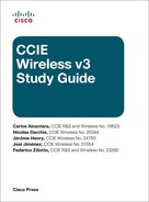
As also shown in Figure 4-1, the split MAC model is equivalent to the “classic” centralized mode, where traffic from/to wireless clients flows inside the CAPWAP data tunnel and through the WLC. Real-time functions, such as beacons and probes, are handled by the AP and non-real time functions are concentrated on the WLC, like 802.11 authentication and association frames.
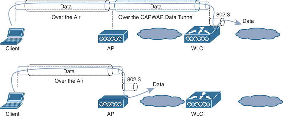
Figure 4-1 Central Switching (Split MAC) and Local Switching (Local MAC) With local MAC, all 802.11 MAC functions are performed at the AP level. Technically, this mode allows the client’s traffic to be either locally switched at the AP level or tunneled in 802.3 frames to the WLC. The latter is not supported by Cisco WLCs, and we can compare local MAC to FlexConnect local switching (and local authentication too, if enabled).
An AP communicates with its WLC through two CAPWAP tunnels: a control tunnel on UDP port 5246 and a data tunnel on UDP port 5247. The CAPWAP control tunnel is always SSL/TLS secured, and we refer to SSL/TLS over UDP as Datagram Transport Layer Security (DTLS). The CAPWAP data tunnel is not encrypted by default, but you can optionally enable DTLS security on a per-AP basis or also globally for all APs.
The CAPWAP protocol integrates Path MTU (PMTU) discovery, which allows the AP and the WLC to automatically discover and adjust the MTU supported on the link between them.
Among different WLC models we can distinguish between three main categories: appliance based, virtual, and Mobility Express. Appliance-based controllers are the more common and “classic” models, supporting all the software features; a typical example of an appliance-based WLC is the AIR-CT5508-K9. A virtual WLC (vWLC), although very close to an appliance-based WLC in terms of supported features, is mainly recommended for FlexConnect deployments with local switching. FlexConnect central switching is also supported on a vWLC, but it’s generally not recommended because of its maximum throughput of 500 Mbps, which may limit future growth possibilities of the deployment itself. A vWLC does not support some features for centrally switched architectures, such as APs in mesh (that is, Bridge) mode (although Flex+Bridge is still supported), the mobility anchor role (although you can still deploy a vWLC as mobility foreign), AVC profiles and NetFlow records for centrally switched WLANs, and others. More details on nonsupported features for the vWLC can be found in the official release notes of each AireOS version (for example, “Release Notes for Cisco Wireless Controllers and Lightweight Access Points for Cisco Wireless Release 8.3.130, 8.3.132.0, and 8.3.133.0”).
Central and FlexConnect locally switched architectures have been deployed for many years. You can find more details on these operational modes in the official “Enterprise Mobility 8.1 Design Guide.” (More recent versions of this guide are already available at the time of this book’s writing, but the current CCIE Wireless blueprint v3.1 is based on AireOS 8.3.) Nevertheless, we will still spend some time describing them to introduce some terms and conventions that we will reuse in the next sections.
The centralized mode is the most classic deployment option, where wireless clients’ traffic is carried between the APs and the WLC in the CAPWAP data tunnel. The WLC (or more precisely, its interface/VLAN, where clients are switched) becomes the point of presence for wireless clients on the network.
Sometime this deployment option is also referred to as central switching, or centrally switched, although these naming conventions are more used for FlexConnect local and central switching.
To make things easier to remember, when an AP is in the so called default “local” mode, as shown in Figure 4-2, the traffic for all wireless clients is centrally switched through the WLC. Another option for switching traffic centrally is the Bridge mode on the APs, which is used for mesh deployments (more on this in the dedicated section).
FlexConnect is the deployment mode that allows mixing and matching options for switching traffic centrally or locally. The FlexConnect name was introduced as of AireOS 7.2 to replace the former Hybrid Remote Edge Access Point (H-REAP). We describe FlexConnect architectures and options more in detail in a later section of this chapter, but a brief introduction is still needed to clarify some terms and concepts used in the following paragraphs.
We use the expression local switching when a wireless client’s traffic is switched locally on a VLAN of the switch port where the AP is connected, instead of centrally switched through the WLC.
The AP itself obtains its IP address from either the access VLAN of a port in access mode or the native VLAN of a trunk port. Wireless clients can be locally switched on the same VLAN as the AP, or on a different VLAN if available on the trunk port.
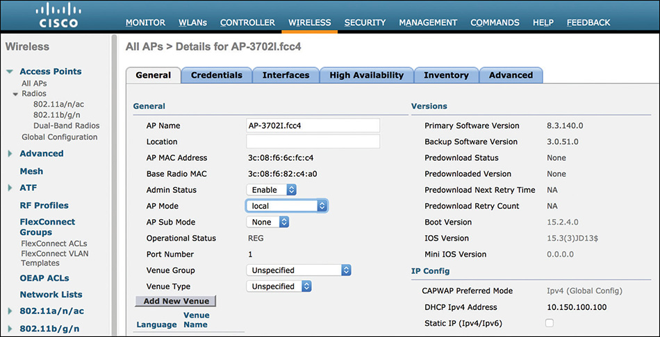
For wireless clients’ traffic from a specific WLAN to be locally switched, at least two conditions must be met: the AP mode must be FlexConnect and the option for FlexConnect Local Switching must be checked under the FlexConnect settings of the WLAN’s Advanced tab options, as shown in Figure 4-3.
If the AP is in FlexConnect mode but FlexConnect Local Switching is not enabled under the WLAN, data traffic is centrally switched through the WLC, just as if the AP was in local mode. We can also refer to this scenario as (FlexConnect) central switching.
On top of central and local switching modes, we can also distinguish two options for authenticating wireless clients. We speak about central authentication when the WLC itself handles authentications, either through the internal database or more commonly by communicating with an external RADIUS server. Conversely, local authentication refers to the AP managing authentications against its local database, or acting as a NAD/AAA client for an external RADIUS server.
Central authentication is the most commonly used option and the only one supported for APs in local or Bridge mode. For FlexConnect (or even Flex+Bridge) APs, you can deploy both, although central authentication is still the recommended one, while keeping local authentication as a fallback.
Mobility Express
Although an official “Cisco Mobility Express Deployment Guide” exists, we want to spend few paragraphs reintroducing this more recent architecture, because we think that additional clarifications on this topic could still benefit CCIE Wireless candidates.
Mobility Express, sometimes abbreviated ME, is the newest deployment type, and you can think of it as a vWLC running on an AP. Well, almost. The main goals for ME are simplicity and ease of use, so compared to a vWLC, some menus and features are not supported and not displayed on purpose. The general rules with ME are that whatever is available through the GUI is supported, and features listed in the official command reference guide are supported too:
Any other WLC feature that is neither available through the GUI nor mentioned in the command references, although maybe still visible via the CLI, should be treated as not supported for ME.
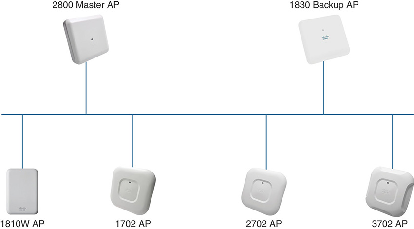
The 1800/2800/3800 series APs (that is, all APs supporting the 802.11ac Wave 2 certification, except the 1810 series APs) are the models supporting the ME controller function (the Master AP role, described in the next paragraphs), which enable customers to easily deploy wireless networks for small and midsize businesses (SMB), branches, or any other installation requiring up to 25 APs. Although not part of the current CCIE Wireless exam, at the time of this book’s writing, the 1815, 1540, and 1560 series APs also support the role of Master AP, and as of AireOS version 8.4 or later, a Mobility Express deployment can scale beyond 25 APs.
One 1800, 2800, or 3800 AP acts as a virtual controller to configure and monitor all the wireless networks of the Mobility Express deployment: such an AP is called the Master AP. The full list of AP models that can support the Master AP role in AireOS version 8.3 is the 1832, 1852, 2802, and 3802.
Note
The 1810 series AP cannot act as a Master AP or its backup, but can still be registered as a standard AP to a Mobility Express deployment.
The Master AP is the central point of configuration and management for any other AP that registers to the Master AP, as in any other classic WLC-based architecture.
Only one 1800/2800/3800 AP can act as the Master AP at any given time. Any other 1800/2800/3800 series AP registered to the Master AP can automatically take over the role of Master AP (except the 1810 series AP), in case the originally designated one becomes unreachable.
Access points from other series (700, 1600, 1700, 2600, 2700, 3600, 3700, and 1810) can be registered to an 1800/2800/3800 series Master AP, although they do not support the Master AP role. Figure 4-4 shows an example of the Mobility Express architecture.
For all the configuration and monitoring tasks, the Master AP communicates with other APs of the same Mobility Express deployment through the standard CAPWAP control tunnel. Data traffic for wireless clients is locally switched directly on the switch port behind each AP, the Master AP’s one included. This corresponds exactly to the same behavior as for FlexConnect local switching when deploying a dedicated physical/ virtual WLC.
Note
We refer to the Master AP as the controller component/service running on an 1800/2800/3800 series AP. On top of that, a “standard” AP component is also present, which registers to the Master AP running on the same AP. For such a reason, the same AP “box” consumes two different IP addresses on the same VLAN/subnet: one for the WLC service and one for the AP itself.
The Master AP is also the point of contact for other external Cisco and third-party resources, such as Cisco Prime Infrastructure, Cisco Identity Services Engine (ISE) or any other RADIUS server, Cisco Connected Mobile Experiences (CMX), SYSLOG or SNMP servers, and so on. Other APs of the Mobility Express deployment registered to the Master AP do not necessarily need to communicate directly with such external resources.
An 1800/2800/3800 series AP can be ordered with the Mobility Express mode already enabled in the preinstalled image. The reference, or stock keeping unit (SKU), to choose when placing the order should end with K9C, C standing for “configurable.” For example, to order an 1852 AP with internal antennas for the -E (ETSI, European Telecommunications Standards Institute) radio regulatory domain, you should choose the reference AIR-AP1852I-E-K9C. Under the options for Software, you should verify that SW1850-MECPWP-K9 for “Cisco 1850 Series Mobility Express software image” is also selected. This should be the default option for AP SKUs ending with K9C.
An out-of-the-box Mobility Express enabled AP, configured with factory defaults, if connected to a network where no other Master AP or WLC can be discovered, automatically starts broadcasting a wireless network (or Service Set Identifier [SSID]) called CiscoAirProvision, on which you can connect to start configuring the ME solution through an initial setup wizard. You can also change the operational mode of an 1800/2800/3800 series AP from standard CAPWAP mode to Mobility Express, for example, if it was previously registered to another WLC or ordered without the K9C SKU.
The first device to configure when deploying the Mobility Express solution is the Master AP. After the Master AP is operational, you can expand your ME deployment by automatically registering additional APs.
An out-of-the-box 1800/2800/3800 series AP, with the K9C SKU, or a newly CAPWAP-to-Mobility-Express converted 1800/2800/3800 series AP will boot up with factory defaults, ready to be configured as a Master AP.
The deployment model being the same as for FlexConnect local switching, before connecting the designated Master AP to a switch, a common practice is to preconfigure the switch port as a trunk. The Master AP, or any other AP of the Mobility Express solutions, will get its management IP from the native VLAN of the trunk port. A trunk port would also allow you to switch client’s data traffic on different VLANs, to separate your management network from your client’s data networks. If you cannot or don’t want to configure the switch port as a trunk and keep it as an access port, management traffic will be switched on the access VLAN, as well as any other client’s data traffic.
After booting, the AP attempts to obtain an IP address through DHCP first. If this phase is successful, it then tries to perform an L2 broadcast discovery for any other potential Master AP on the same VLAN, which would be the native VLAN of the trunk port or the access VLAN. If no other Master AP is available, the 1800/2800/3800 series AP autodeclares itself as the Master AP and starts broadcasting the SSID CiscoAirProvision. Similarly, in case the AP cannot initially get an IP via DHCP, it activates the graphical interface for initial setup on the management IP 192.168.1.1 (reachable over Wi-Fi only), then autodeclares itself as the Master AP and starts broadcasting the SSID CiscoAirProvision. Figure 4-5 shows a more graphic workflow of the Master AP’s state machine during the initial boot.
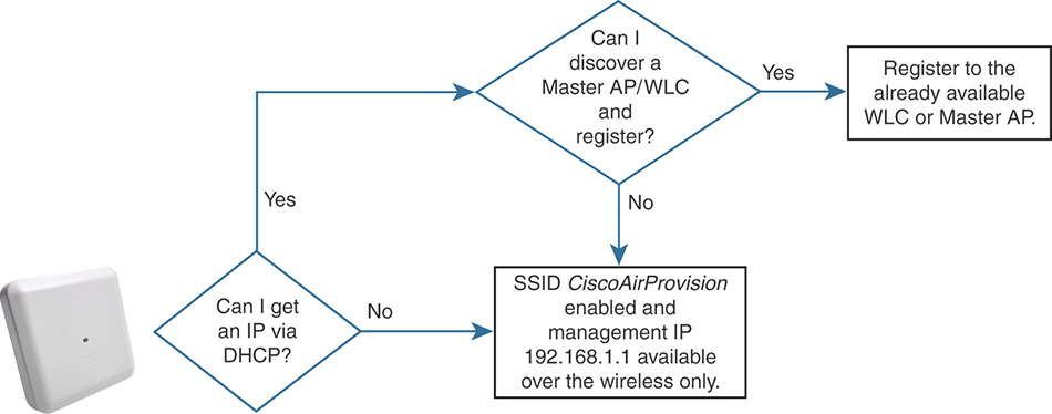
The SSID CiscoAirProvision is protected with WPA2 PSK and the passphrase is “password”.
After entering the “password” password (apologies for the wording joke) and getting connected to the SSID CiscoAirProvision, your machine should obtain an IP address in the 192.168.1.0/24 network; as part of the initial configuration process, in fact, the Master AP automatically enabled an internal DHCP server too.
If you open a web browser and try to access any website, you should automatically be redirected to the following URL: http://mobilityexpress.cisco/screens/day0-config.html. If you are not automatically redirected (web browsers may cache already visited pages or may not accept untrusted certificates redirections), you can always access the initial setup wizard directly at http://192.168.1.1. From here, the initial configuration steps are intuitive and easy to complete.
Note
The setup wizard proposes to configure WLANs with corresponding DHCP pools and servers, which could run locally on the Master AP or on external DHCP servers. A mix of DHCP pools from the Master AP’s internal DHCP server and pools from external DHCP servers is not supported. If you enable an internal DHCP pool for the Management Network, for example, you must keep using internal DHCP pools for your WLANs too.
After setting up the Master AP, additional access points can discover and register to it. As compared to a “standard” (v)WLC, the only discovery process supported with Mobility Express is through L2 broadcast requests on the same subnet, where the AP obtains an IP address. For such a reason, new APs should be connected to the same management VLAN as the one where you originally connected the Master AP.
A new AP registering to the Master AP, if it is not already running the same version, needs to download the same image version as the Master AP. The Master AP does not store AP images in its flash memory. As shown in Figure 4-6, when a new AP needs to update its image, the Master AP first downloads the new AP’s image via TFTP and then provisions the newly registered AP with such an image. These two phases run almost in parallel.
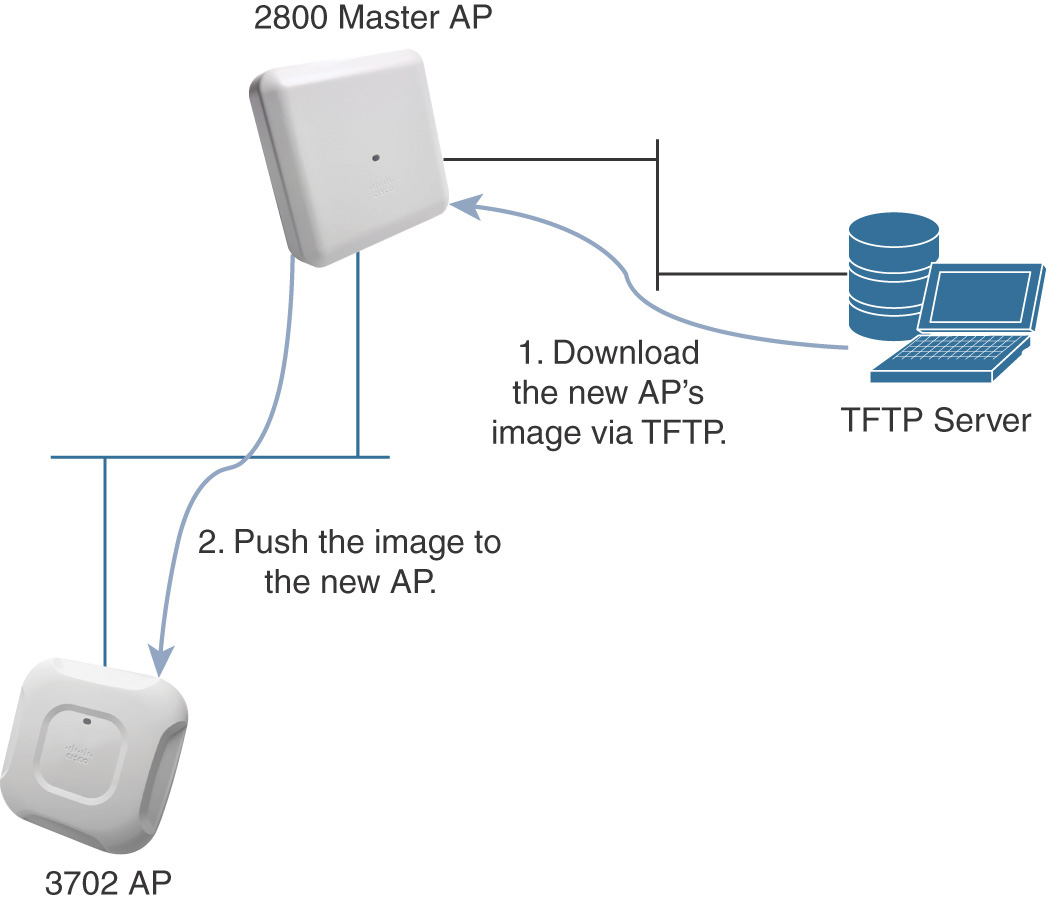
As of version 8.3, if the Master AP can join Cisco.com, you can also push software updates directly from Cisco.com to all the 1800/2800/3800 APs of your Mobility Express deployment. Other AP models, if deployed, would still need to go through the TFTP procedure.
If the originally designated Master AP is not reachable anymore, its role can be taken over at any time by another 1800/2800/3800 series AP of the same Mobility Express deployment, except for the 1810 series APs.
The Master AP and its backup(s) do not need to be of the same model; they can be any mix of 1800/2800/3800 APs, but it is generally recommended to keep the same model for consistency.
Note
Up to AireOS 8.3, Mobility Express is limited to 25 APs, so any 1800/2800/3800 series AP will support the Master AP role with the same scaling numbers. Starting from AireOS 8.4, and as of 8.5, 1540, and 1800 series APs acting as a Master AP support up to 50 registered APs; 1560, 2800, and 3800 series APs acting as a Master AP support up to 100 registered APs. The Mobility Express deployment’s scale can go as high as the Master AP allows (that is, 50 or 100 APs). In such a scenario, if deploying a 1560/2800/3800 series AP as the Master AP, you may want to use APs from the same series (or at least with the same scaling numbers) as backups for the Master AP role.
Newly registered 1800/2800/3800 APs automatically detect the current Master AP and synchronize through Virtual Router Redundancy Protocol (VRRP). Such a protocol allows all the 1800/2800/3800 series APs in the same Mobility Express deployment to detect whether the Master AP is not reachable anymore and to automatically elect a new Master AP.
Because VRRP is supported only between devices on the same subnet, it is fundamental that all the APs of the same Mobility Express deployment are connected to the same management VLAN. During the election process of a new Master AP, the traffic of wireless clients already connected to other APs is not impacted, because it is locally switched at each AP’s level and does not need to flow centrally through the Master AP.
Mobility Express is mainly targeted for small, simple, and isolated deployments. As such, there are some scenarios and features that could not be supported on ME or where ME could present some advantages compared to a standard WLC:
Mobility tunnels between one Master AP and another, or between a Master AP and a physical/virtual WLC, are not supported. As a consequence, inter-controller roaming or guest anchoring are not supported either with Mobility Express.
Radio Resource Management (RRM) RF grouping between Master APs of different Mobility Express deployments, or between a Master AP and another “standard” WLC, is not officially recommended or supported.
ME does not support customization of the RF Group name, which is set automatically to the system name that you configure through the initial setup wizard of the Master AP. Although you could technically install two or more ME deployments with the same Master AP’s system name to have the same RF Group everywhere, this would not be recommended or officially supported, because it could still create other conflicts and confusion.
Location and aWIPS services are not compatible with Mobility Express, but Presence with CMX is supported (more on all these solutions in Chapter 6, “Prime Infrastructure and MSE/CMX”).
Because we could technically think of the Master AP as a WLC and an AP all in one box, in some situations you could use Mobility Express for site surveys instead of deploying a dedicated WLC. More details on this are available in the chapter “Configuring Mobility Express for Site Survey” of the official Cisco Mobility Express Deployment Guide.
For the CCIE Wireless exam purpose, in the next sections of this chapter we refer to solutions and features applicable to a “standard” dedicated WLC only. Mobility Express may or may not support some of them, and you can find further detail on this solution in its official deployment guide:
Securing Management Access and Control Plane
Following from the very first installation and setup of a WLC, a good practice is to configure security options to secure management access. The options could go from admin user authenticated access, to traffic restrictions to/from the WLC through CPU ACLs, to disabling specific options for wireless and wired access. Before detailing these common practices, we want to say a few words on SNMP settings, usually relevant when integrating the WLC with Cisco Prime Infrastructure or other external management and monitoring tools in general.
A WLC by default has SNMPv1 disabled, and it is a good practice to keep it that way, whereas SNMPv2c and SNMPv3 are enabled. Always by default, SNMPv2 communities are “public” for read operations and “private” for read-write operations, and access is allowed from any network. It would be a secure practice either to disable SNMPv2c and use SNMPv3 or to change communities and restrict access to/from needed resources and networks only, by trying to be as specific as possible. SNMPv3’s default read-write user and password are all set to “default”: you may want to either disable SNMPv3 if not used or change the default values to more secure ones. You probably already guessed the philosophy behind, not necessarily just for security, but for best practices in general and simplicity purposes: if a feature is neither needed nor used by other components, keep it disabled.
Admin User Authentication and Authorization
You can authenticate WLC administrators against the WLC’s internal database or even through an external authentication server. Accounts created in the internal database can have read or read-write access to all of the WLC’s tasks.
Note
To align with the jargon sometime used in the configuration examples, as shown in Figure 4-7, we refer here to the WLC’s “tasks” as the main menu tabs on top of the graphical user interface (GUI): MONITOR, WLANs, CONTROLLER, WIRELESS, SECURITY, MANAGEMENT, COMMANDS.

If instead of the WLC’s internal database you would like to authenticate management users through an external database, you can configure admin access through a RADIUS or a TACACS+ authentication server.
When authenticating admin users via RADIUS, the types of privileges you can assign them are the same as for users from the WLC’s internal database: you can distinguish between read-only or read-write access. The authentication server can assign read privileges by returning the IETF RADIUS attribute “[6] Service-Type” with a value of 7 for NAS Prompt in the final Access-Accept response. For read-write privileges, a value of 6 for Administrative should be passed back in the same RADIUS attribute.
Additional configuration details can be found in the “RADIUS Server Authentication of Management Users on Wireless LAN Controller (WLC) Configuration Example”:
When authenticating admin users via TACACS+, on top of read-only or read-write access privileges, you can also specify which “tasks,” or main menus, the admin user has write access to. The authentication server can pass back TACACS+ custom attributes in the form of role1, role2, role3, and so on, with values corresponding to the equivalent tasks the user should have access to: MONITOR, WLANs, CONTROLLER, WIRELESS, SECURITY, MANAGEMENT, COMMANDS, ALL, and LOBBY. For example, if you would like to grant write access to the WLANs and SECURITY tasks, the TACACS+ server should pass back the following attributes:
role1=WLAN
role2=SECURITY
Note
There is no mistake in the example; for the WLANs task on the WLC, the TACACS+ attribute should contain the value WLAN without the “s.”
If you would like to grant write access to all tasks, the TACACS+ server can pass back the custom attribute role1=ALL. The value LOBBY should be used to authenticate lobby ambassador users only.
To grant read-only access, no custom role attributes are needed: if the TACACS+ server successfully authenticates an admin user, that user automatically has read access to all the tasks. Read access privileges cannot be limited to some specific tasks only. This also implies that an admin user successfully authenticated with write privileges to a specific task, for example, still has read privileges to all other tasks.
An example of TACACS+ management access to the WLC with Cisco ISE as the authentication server can be found at the following URL:
TACACS+ authorization for WLC’s admin users does not allow being more granular than the aforementioned tasks. If a user has read-only or read-write access to a specific task, he/she has read-only or read-write access to all the menus and features supported under that task too. This is different from Cisco IOS-based switches, for example, where you can implement authorization for single commands.
In large deployments, a common management need for some customers is to have different WLC administrators from different offices with access to configure just the SSID(s) corresponding to their respective sites. We cannot address such a need on the WLC directly, or with just one single WLC for that matter. An option could be to deploy one (v)WLC or even one Mobility Express setup per site, with its corresponding admin user(s) and SSID(s). Each site and controller could also be part of a dedicated virtual domain in Cisco Prime Infrastructure, for additional separation of admin access and monitoring features through a centralized management solution.
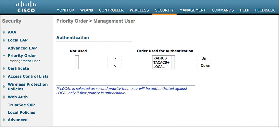
As shown in Figure 4-8, on the WLC you can specify the priority of the three different admin user authentication options under SECURITY > Priority Order > Management User. For example, the WLC can first attempt TACACS+ servers to authenticate an admin user and then fall back to the local database if no TACACS+ server replies. Be aware that if a RADIUS/TACACS+ server replies by rejecting the admin user, that still counts as a valid response and the WLC does not fall back to the next option in the priority list. If by accident you cut yourself out of the WLC by configuring RADIUS/TACACS+ as higher priority options than the LOCAL one (as this writer already experienced back in the early days), to work that around you could always deny WLC’s traffic to/from those RADIUS/TACACS+ servers through an ACL on the wired infrastructure, to force the WLC to fall back to the local database.
CPU Access Control Lists
To filter control plane traffic to/from specific networks or even IP addresses, you can additionally configure CPU ACLs. The WLC’s CPU handles protocols for management access, CAPWAP control traffic, RADIUS, DHCP, and so on, and traffic to the CPU is defined as all traffic destined to any of the WLC’s interfaces (management, ap-manager, dynamic and virtual), as well as to the service port. Traffic between wireless clients or between wireless and wired clients is not handled by the WLC’s CPU but by the data plane, and should be filtered through ACLs applied to the dynamic interface, the WLAN, dynamically assigned via RADIUS or through a local policy too.
Note
Traffic between wireless clients tunneled to an anchor WLC and the rest of the wired network behind that anchor is carried through an Ethernet over IP (EoIP) tunnel from the foreign WLC to the anchor WLC. The EoIP tunnel is established between the management interfaces of the two WLCs; therefore, although we are talking about traffic between wireless and wired clients, a CPU ACL not allowing EoIP tunnels between the two WLCs would automatically block traffic between wireless and wired clients too.
To configure a CPU ACL, you first need to create an ACL under SECURITY > Access Control Lists > Access Control Lists and then apply that ACL to the CPU itself under SECURITY > Access Control Lists > CPU Access Control Lists.
The direction of an ACL’s rule (inbound or outbound) is not taken into account when applied to the CPU: for example, to block traffic from the 192.168.1.0/24 network, in the ACL’s rule you can configure that network as the source, leave all other options (for example, destination, protocol, direction) to any, and set it to deny.
Before getting your hands dirty with so-called strict ACLs (with a “deny all” rule at the end), it is generally recommended that you practice CPU ACLs with a “permit all” rule at the end, not to risk blocking yourself out of the WLC (in which case, only console access or a WLC’s hard reboot may save your day, by causing the controller to reload without the latest nonsaved changes, including the CPU ACL itself). You can always check the currently allowed/denied control plane services by using the show rules command.
Even if you can block wireless users from managing the WLC by disabling the Management Via Wireless option (more on this in the next section), those users will still be able to test and see management protocol ports for SSH, HTTPS, and so on. To prevent this, you may want to configure a CPU ACL to block traffic from wireless users’ networks. An exception could apply to wireless users authenticating with Local Web Authentication (LWA). This authentication technique requires wireless users to get redirected via HTTP(S) to the WLC’s virtual interface, which should then be permitted if a CPU ACL is in place.
On top of using CPU ACLs for security goals, you might also want to configure them to optimize the WLC’s performances overall. By selectively limiting which protocols and resources can be handled by the WLC’s CPU, in large networks you can avoid unneeded traffic to hit the WLC’s interfaces and be processed by the CPU.
You can find a useful configuration guide for CPU ACLs at the following link:
Management via Wireless and via Dynamic Interface
Even before configuring CPU ACLs, you may want to consider options to allow or block management access for wireless users or even for managing the WLC through one of its dynamic interfaces’ networks.
Management Via Wireless is disabled by default and can be configured under MANAGEMENT > Mgmt Via Wireless > Management Via Wireless. Even when disabled, wireless clients connected through the WLC can open connections for management protocols (for example, SSH, HTTPS, and so on) enabled on that WLC, and also get to the SSH login prompt, for example (the session will anyway be blocked when attempting to log in). For such a reason, when blocking management access for wireless users, a CPU ACL should also be deployed on top.
For ease of management, however, sometime you may want to have a dedicated WLAN or subnet through which you can access the WLC while being connected to your APs and verify your wireless deployment, for example. In such a case, you could enable Management Via Wireless, assign your management users to a dedicated subnet, and then allow that subnet on a CPU ACL, while denying traffic for other wireless users’ networks on that very same ACL.
Note
Management Via Wireless is a global setting. When enabled, and without a CPU ACL, any wireless user with the right admin credentials can gain management access to the WLC through the management interface or the service port (assuming that the needed switching and routing infrastructure is configured accordingly). Through a CPU ACL you can filter management access through specific networks only. A wireless management user could connect through a dedicated WLAN associated to that specific network. Alternatively, while connecting through the same 802.1X-enabled WLAN as for other users, for example, through RADIUS attributes you can dynamically assign management users to the management VLAN/subnet allowed on the CPU ACL.
Management Via Dynamic Interface is also disabled by default and can be configured via command line interface (CLI) only, through the following command:
config network mgmt-via-dynamic-interface [enable | disable]
When enabled, this feature allows users on the same VLAN/subnet as one of the WLC’s dynamic interfaces to gain management access through the dynamic interface’s IP of the WLC on that very same VLAN/subnet. Access through the management interface is permitted too.
Working with WLC Interfaces
Configuring and preparing interfaces is another prerequisite for successfully deploying your wireless infrastructure with a WLC. Each interface can be assigned to a specific physical port, or all interfaces can be assigned to the same port, or they can also all be aggregated through Link AGgregation (LAG).
If you assign different interfaces to different physical ports, each port must have an AP-manager interface. Using different ports for different interfaces was originally introduced to have multiple AP-manager interfaces on multiple ports and load balance LWAPP traffic for the APs, back when WLC hardware models supported only two Gigabit Ethernet interfaces with no aggregation options. That heritage is still there: when multiple ports are used for different interfaces with no LAG, the WLC expects an AP-manager interface dedicated to each of those ports.
The two most common scenarios as of today are either to use a single port for all interfaces or to use LAG. Both these options often imply that the WLC is connected to a switch port or a port-channel in trunk mode, to support multiple VLANs.
Management and AP-Manager Interfaces
The management interface is the first one you need to configure when installing a WLC. As the name says, it provides management access to the WLC but also CAPWAP discovery responses to the APs, as well as communication with other WLCs and external resources.
Before trying to register to a WLC, an AP needs to discover that WLC through its management IP. The AP learns a WLC’s management IP in many ways: via DHCP option 43, through DNS resolution, trying a L2 broadcast discovery, and others. The WLC replies to a discovery request on its management IP by sending back a response with the information of the AP-manager interface’s IP, which is the one the APs will use to register and exchange CAPWAP traffic with.
This separation between management and AP-manager interfaces was probably more intuitive in the past, when the WLC required configuring one management interface and one separate AP-manager interface. Since some years and some AireOS versions, the management interface carries the role of AP-manager too, so this separation between the two interfaces is less explicit, although logically still present. By default we were using the same physical port (or just all ports in case of LAG) for both the manager and AP-manager interfaces, but other ports could be used under the condition of creating a new dedicated AP-manager interface for each of those ports. Nowadays we tend to keep just one AP-manager interface, corresponding to the management one, and to use either just one port or LAG.
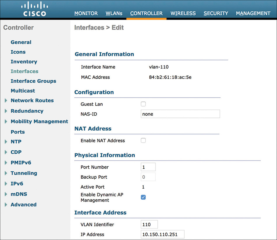
If you want to assign one or more (dynamic) interfaces to other ports than the management interface’s port, each one of those other ports must have a dynamic interface enabled for Dynamic AP Management (that is, with an AP-manager role). Figure 4-9 shows the option to enable the AP-manager role on a dynamic interface.
The management interface has the option Dynamic AP Management enabled by default. If you configure LAG, only one interface can act as the AP-manager, and that will be the management interface by default.
When using an interface as an AP-manager with Dynamic AP Management enabled, you should not configure any backup port. Backup for AP-manager interfaces on multiple ports should be implemented implicitly by the requirement to have an AP-manager per port already.
In your daily job as a wireless expert you might encounter organizations asking for the APs to communicate with the WLC through a dedicated IP on a dedicated port only, which should be physically separated from the management interface and port. This is not completely possible: APs must be able to initially reach the WLC’s management IP, at least for the very first discovery phase, so at that point going through an AP-manager on a different port might not make too much of a difference in terms of segmentation. The common recommendation would be to keep using the management interface as the AP-manager, too, and maybe apply additional filtering and security options on its VLAN/subnet.
To further address some security needs, as well as APs’ registration over a public IP, the management interface supports NAT configuration. When you configure the NAT option and the corresponding public IP under the management’s interface settings, the WLC replies back to discovery requests with the public IP from the NAT option as the IP for the AP-manager, which APs should register to. This NAT IP could then translate to any interface with Dynamic AP Management enabled.
Note
When NAT is configured, by default the WLC will communicate only the NAT IP in discovery responses. If you need to register APs across both NAT and the internal network, for example, you may want the WLC to reply with both the NAT IP and its internal IP. In such a case, you could use the following command to enable/disable the NAT IP only in discovery responses:
config network ap-discovery nat-ip-only [enable | disable]
The management interface is also by default the dedicated one for communications with external resources, such as SNMP trap receivers, MSE and CMX, as well as RADIUS/TACACS+ servers, SYSLOG servers, and so on. For RADIUS traffic, you can change the default behavior on a per WLAN basis, to have this particular traffic sourced from the dynamic interface associated to that WLAN instead. For WLC models supporting an internal DHCP server, if you need to use such a capability (although generally not recommended for production environments), under the settings of the interface associated to the WLAN, you should configure the DHCP server’s field with the management IP itself.
Multicast traffic for centrally switched wireless clients is also delivered from the management interface to the APs. This is slightly different from the standard mode of operations, where the WLC’s AP-manager interface (although commonly corresponding to the management one) usually communicates with the APs via CAPWAP for the data tunnel.
Inter-WLC communications also flow through the management interfaces. This includes EoIP tunnels for clients’ traffic and the Mobility protocol for control messages, as well as synchronization between WLCs for RF management with RRM.
Last but not least, although you may not associate the management interface with any WLAN, it is still a good practice to tag the management interface on a specific VLAN for Quality of Service (QoS) optimization. Without an 802.1q tag there is no support for Class of Service (CoS) markings. Even if not used for wireless clients, you could still need this for prioritizing CAPWAP control traffic, inter-WLC communications, and any other traffic to/from the management/AP-manager interface in general.
Service Port
If the service port is supported by the WLC model in use, it is another interface that the initial WLC’s setup wizard asks you to configure. If you don’t plan to use any, you can simply define a bogus IP (on a completely different super-net from the management interface) and keep the option for a DHCP assigned address disabled.
The service port was originally designed to provide out-of-band management to the WLC’s GUI or CLI. Since AireOS 8.2, the service port also supports SNMP and SYSLOG traffic, as well as download and upload operations. The IP address of the service port should always be on a different super-net from the management interface’s IP. For example, if the management IP is configured as 10.10.0.250 in the 10.10.0.0/24 network, the service port’s IP could be something like 172.16.0.250 in the 172.16.0.0/24 network.
When configuring the service port, you may notice that there is no option to configure its default gateway. For such a reason, some WLC models support configuring static network routes, to specify out-of-band management traffic routing.
Virtual Interface
The virtual interface is another interface that the WLC’s installation script asks you to configure during the initial setup. A common convention in the past was to use odd enough, nonrouted IP addresses such as 1.1.1.1, 2.2.2.2, 3.3.3.3, and so on. Since then, address ranges in networks such as 1.0.0.0/8, 2.0.0.0/8, and 3.0.0.0/8 have been allocated by IANA to specific organizations. Following the RFC 5737, the current recommended best practice is to use an IP from blocks used for documentation, such as the IP 192.0.2.1 from the 192.0.2.0/24 network.
Controllers verify whether they have the same virtual IP in order to successfully exchange mobility messages. This is one first prerequisite if you plan to deploy WLCs in the same mobility domain or mobility group.
Another usage of the virtual IP is to host the WLC’s internal web server for all web redirection scenarios based on Local Web Authentication (LWA). With a web redirect enabled WLAN, no matter if for web authentication or simply web passthrough, users go through the WLC’s internal web server hosted on the virtual interface. When using HTTPS for web redirections, enabled by default under MANAGEMENT > HTTP-HTTPS > WebAuth SecureWeb, the WLC presents a dedicated certificate tied to the virtual IP or FQDN (if configured). This plays an important role when deploying a publicly signed certificate for the virtual interface. Such a certificate should be issued with the virtual IP in the certificate’s common name, or else with the virtual interface’s FQDN (if configured) in the common name plus the virtual IP in the subject alternative name (SAN) IP and DNS options.
Note
When using a publicly signed certificate for this purpose and using a FQDN in a certificate’s CN (also configuring it at the WLC for the virtual interface), the wireless clients are redirected to the WLC’s internal web server by the WLC giving the URL of the virtual interface using the FQDN instead of the IP address. Hence, clients should be able to perform DNS resolution for the virtual IP with their DNS server(s), even though that may mean adding a public DNS entry pointed to a private address, which can be counterintuitive to some enterprises.
If not publicly signed, such a certificate is automatically generated as a self-signed one during the initial WLC’s installation, with the first virtual IP that you specify through the setup wizard as the common name of that certificate. You can of course modify the virtual IP and FQDN later on (you need to reboot the WLC for the new virtual IP/FQDN to be applied), but the self-signed certificate will keep the initially configured virtual IP in the common name until you regenerate such a certificate under SECURITY > Web Auth > Certificate (a WLC’s reboot is needed for the new certificate to take effect).
One more function of the virtual interface is as a placeholder for the DHCP server IP when DHCP proxy is enabled (globally or at the dynamic interface level).
Dynamic Interfaces
Although you can associate a WLAN with the management interface, you usually may want to assign your wireless clients to a different VLAN. This is the main purpose of a dynamic interface: switching traffic of a specific WLAN or client on the corresponding VLAN. Even if the WLC is not a routing device and simply switches client traffic on different VLANs, you still need to reserve an IP for the WLC on the needed VLAN when configuring the corresponding dynamic interface. A dynamic interface can be assigned to a specific port, or to all ports through LAG. If DHCP proxy is enabled on the WLC, DHCP requests from clients assigned to a dynamic interface are proxied through that dynamic interface’s IP.
Note
You can enable DHCP proxy at a global level, for management and dynamic interfaces, and at a local level, too, for each interface. The specific interface’s DHCP proxy configuration under the interface options overrides the global DHCP proxy settings.
If the subnet of a single dynamic interface does not allow you to allocate enough IP addresses to wireless clients of a WLAN, you can also bundle more dynamic interfaces together through an Interface Group (a.k.a., VLAN Select or VLAN Pool[ing], when the feature was originally introduced). When a client associates to the WLAN linked to an interface group, an index is calculated based on a hashing of the client’s MAC and the number of dynamic interfaces in the interface group. This index is used to decide which interface of the group the client should be assigned to. Such a hashing technique guarantees that the same client is always assigned to the same interface of the group, as long as the interface group’s configuration does not change (for example, you do not add/remove interfaces to the group). It also avoids IP addresses exhaustion if the client would have been assigned to a different interface of the group at each reconnection. If a DHCP timeout occurs for clients on an interface, or if three unsuccessful DHCP attempts happen three times on that interface, the interface is marked as “dirty,” a new random index is chosen, and the client is assigned to the first “non-dirty” interface starting from that random index and trying other interfaces in a round-robin fashion.
Although written at the time of AireOS 7.2, a good reference for understanding how interface groups work is still the “WLC 7.2 VLAN Select and Multicast Optimization Features Deployment Guide”:
When you create a WLAN and assign a dynamic interface to it, by default wireless clients associated to the WLAN will be switched on that dynamic interface’s VLAN. You can override this behavior by dynamically assigning a different dynamic interface and VLAN with RADIUS attributes, at the end of the client’s authentication process (802.1X, MAB, etc.), or through local policies.
For dynamic VLAN assignment via RADIUS attributes, you have two options:
Using the Cisco Vendor Specific Attribute (VSA) “Airespace-Interface-Name” with the name of the dynamic interface, which a wireless client should be assigned to.
Using the standard RADIUS IETF attributes:
Tunnel-Type=13 (VLAN)
Tunnel-Medium-Type=6 (802)
Tunnel-Private-Group-ID=<VLAN ID/Name>
Where <VLAN ID/Name> could be either the VLAN number of the dynamic interface that you want to assign or the dynamic interface’s name itself.
For a FlexConnect locally switched WLAN, wireless clients are automatically locally switched with the same VLAN ID as the one configured under the dynamic interface associated to the WLAN, so you should make sure that the correct VLAN IDs are also configured on those switches, where FlexConnect APs are connected.
For FlexConnect locally switched clients to be on a different VLAN, you can “remap” the WLAN to a different VLAN under each AP’s FlexConnect settings, or through the WLAN-to-VLAN mappings of a FlexConnect Group, to which you can assign your FlexConnect APs. In this case you do not need to create a dynamic interface for each VLAN on which you want to assign FlexConnect locally switched clients.
Although maybe not needed anymore thanks to the FlexConnect Group options to map a WLAN to a VLAN for a full set of APs at once, a more common technique in the past to remap a WLAN to a VLAN was to assign APs to an AP Group and to remap the WLAN in the AP Group to a dynamic interface on the needed VLAN. The dynamic interface IP didn’t necessarily need to be a “real” one, and even the VLAN didn’t need to exist on the trunk behind the WLC (only behind the FlexConnect APs of course). By having the WLAN mapped to a specific dynamic interface in the AP Group, the VLAN of the dynamic interface itself is automatically used to locally switch clients of that WLAN for the APs in the same AP Group.
When authenticating wireless clients of a WLAN through an external RADIUS server, by default the WLC communicates with RADIUS servers through the management interface. You can modify such a behavior on a per WLAN basis, under the WLAN’s Security > AAA Servers settings, by enabling the option RADIUS Server Overwrite Interface. This will make the WLC source RADIUS traffic for that WLAN from the dynamic interface associated to that WLAN. In your RADIUS server, you need to add the dynamic interface’s IP as a valid AAA client or network access device (NAD).
Note
Although not generally recommended, back in the days in some network designs the RADIUS server was configured with an IP in the same subnet as of a dynamic interface. In such a case, for the WLC to accept RADIUS traffic usually destined to the CPU we had to turn on management via dynamic interface.
LAG: Link Aggregation
For higher bandwidth capacity and interfaces availability, you can aggregate ports of a WLC to a single logical link. The WLC partially implements some of the features from the IEEE 802.3ad standard for Link Aggregation Control Protocol (LACP); however, it does not completely implement the full standard: some features, such as dynamic link negotiation, are not supported. When you configure the interfaces of a Cisco switch for participating to the port-channel, where the WLC is connected, you should force the EtherChannel mode with the command channel-group <id> mode on. Since the WLC also relies on the switch for the traffic’s load-balancing technique, the recommended option for load balancing is based on source and destination IP: on a Cisco Catalyst switch you can configure this with the global command port-channel load-balance src-dst-ip. You can also use LAG with Virtual Switching System (VSS) and Nexus virtual Port-Channel (vPC).
When you enable LAG on the WLC, a reboot is required for changes to take effect; after that, all interfaces will be mapped to a single logical port, ephemerally numbered 29 on the WLC itself.
As previously mentioned when describing the AP-manager interface, if LAG is enabled there can be only one interface carrying the AP-manager role, and by default the management interface is the one. On top of increased bandwidth, you may usually want to implement LAG for ports redundancy. This may not apply if you need to connect the WLC ports to different, nonstacked switches, for example.
Deploying Lightweight Access Points
Following the logical steps of a wireless infrastructure deployment, after choosing your deployment model (centralized or FlexConnect/Mobility Express), configuring your controller, and connecting it to the network, the next phase would be to connect your access points.
Sometimes we still use the adjective “lightweight” to designate APs controlled by a WLC, hence carrying less “weight” on them in terms of configuration and operational tasks. Access points working in standalone mode are often referred to as autonomous. Cisco Internetwork Operating System (IOS) is the operating system used since the introduction of wireless access points in the Cisco portfolio (only APs from initial acquisitions were running different OSes). Both types of APs, lightweight and autonomous, operate on IOS. Lightweight APs are controlled by an AireOS-based WLC, whereas autonomous APs are not controlled by any other network device, except probably a management system via SNMP/SSH/telnet/etc. if you decide to deploy one. Sometime autonomous APs are also designated as IOS-based APs, but that wouldn’t be 100% accurate because lightweight APs are IOS-based too.
The most recent generations of Cisco APs, at least at the time of this book’s writing, are access points supporting the 802.11ac Wave 2 certification, such as the 1800/2800/3800 series or the very latest 1560 and 1540 outdoor series. Starting from these models, Cisco introduced a new operating system referred to as Cisco OS (COS), which was necessary to support the additional performances and options of the 802.11ac Wave 2 certification and other features.
COS-based APs do not support the IOS-based, autonomous deployment model anymore. Well, sort of. COS APs do not support configuring the access point component itself, with its own SSID and radio parameters, for example, in the same way as we were used to with autonomous IOS APs. COS APs can work only in lightweight mode, controlled by a WLC. This means that COS APs can work either with a “standard” WLC (for example, in local or FlexConnect mode), or also in FlexConnect local switching mode with Mobility Express, by registering to the “virtual” WLC (that is, the Master AP) hosted on a COS AP (except for the 1810 series). Mobility Express is therefore the new standalone mode for COS APs. By setting up the WLC hosted on a COS AP and registering that COS AP itself to its own WLC, you can deploy a COS AP as standalone/autonomous and additionally benefit from some WLC-related features, such as Radio Resource Management (RRM), which are not available with autonomous IOS APs.
Both options, autonomous IOS APs and Mobility Express with COS APs, are currently valid and supported for installing a standalone AP. The choice between one and the other may vary according to the final deployment’s needs.
Through the following section and subsections we refer to lightweight APs as controlled through a standard, dedicated WLC.
Authenticating and Authorizing APs on the Network
When connecting an access point to a switch port, you may want to configure additional options to authenticate the AP on the network and/or even at the WLC level during/after the join process.
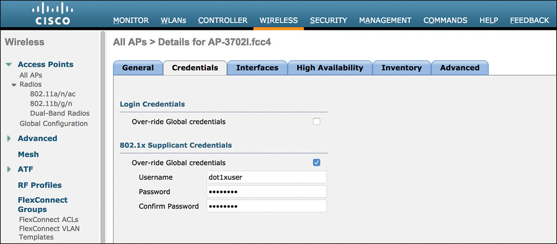
One first level of authentication could be directly through 802.1X on the access switch, where the AP is connected. IOS-based APs support an 802.1X supplicant for the wired/uplink interface. The Extensible Authentication Protocol (EAP) method is EAP-FAST as the tunneling technique, with MS-CHAPv2 as the inner method. The authentication is therefore based on username and password, which you can configure either via CLI on the AP (through the command capwap ap dot1x username [USER] password [PWD] in enable mode, on IOS APs) or through the WLC’s CLI/GUI, for all APs at once, or AP by AP, as shown in Figure 4-10.
Pushing the 802.1X credentials through the WLC implies that the AP must register to the WLC first. The AP should use 802.1X to authenticate to the network even before registering to the WLC, but you could also consider pushing the 802.1X credentials to your APs as a prestaging operation, before activating 802.1X on your switch ports in closed mode, for example.
Note
Unlike IOS APs, COS APs did not support the 802.1X supplicant for wired authentication before AireOS 8.6.
802.1X credentials are stored in the AP itself and encrypted with a type 7 password hash. Because this encryption option is relatively easy to decrypt, someone with physical access to the AP’s console port and with the right login credentials could potentially retrieve the 802.1X username and password.
Common best practices to prevent and mitigate this risk include changing the AP’s login credentials to something more secure than the default “Cisco/Cisco/Cisco” (for login user/password/enable). Another option is to make sure that the network (for example, the VLAN, subnet, VRF, and so on) where APs are deployed restricts communications to the WLC and other minimum required resources but filters access to any other unneeded resource. If someone manages to use the same AP’s 802.1X credentials on other devices, he or she would be limited to CAPWAP traffic to or from the WLC, for example, where additional filtering and authorization techniques could be applied on top. To exploit a feature seen at the beginning of this chapter, you can also configure CPU ACLs for extra control on CAPWAP traffic from the AP’s network to the WLC.
When an AP discovers and tries joining a WLC, you can also enable authorization options for the AP’s certificate type or its MAC address. On the WLC, under Security > AAA > AP Policies, you have the choice of authorizing APs through Self-Signed Certificate (SSC), Manufacturer Installed Certificate (MIC), Local Significant Certificate (LSC), or even by verifying their MAC addresses against a local list or external AAA servers.
Support for self-signed certificates was needed for APs manufactured before July 18, 2005, and converted from autonomous to lightweight. Older models were manufactured before Cisco introduced wireless LAN controllers on the market, so they didn’t have any MIC, for example, because it was not needed for the APs to work in autonomous mode. Those APs were from the 1200, 1130, and 1240 series, which are not supported anymore after AireOS version 8.0 (the 1200 series since even before).
MIC certificates are those preinstalled by Cisco when APs are manufactured, and they are used by default to set up the DTLS communication of the CAPWAP tunnel with the WLC. If an AP can communicate with a WLC, with no other authentication measures in place, it can join with its MIC. For such a reason, some organizations may want to deploy their own certificates, or local significant certificates. It is not a common option, because of the configuration and management overhead that certificates would require, but you can enable APs to download and use new certificates through Simple Certificate Enrollment Protocol (SCEP). The WLC plays the role of a proxy SCEP in this case, by relaying requests for certificates from the APs to the certification authority, and then passing back newly generated certificates to the APs. To validate the new APs’ certificates, the WLC also downloads the root certification authority (CA) certificate from that same authority. All the configuration details for LSC certificates are available in the official “Locally Significant Certificates on Wireless LAN Controllers Configuration Example”:
As you may have already guessed, an LSC certificate can be pushed only after an AP has already joined the WLC, and this could appear a bit as a chicken-and-egg challenge. Enabling both options for MIC and LSC certificates could defy the principle of using LSC certificates to avoid generic APs registering to the WLC. On the other side, MIC certificates support is needed at least during the first phase, to be able to push LSC certificates. At a second stage, after having deployed all your APs with their corresponding LSC certificates, you may want to disable support for MIC certificates, to block other potentially unknown APs that managed to communicate with the WLC and tried to join it. However, you could also use a staging WLC (which allows MIC) to let new APs join for the first time in your network, onboard the APs with their LSC certificates from this staging WLC, and then get them to join the proper production WLCs.
A simpler option to authorize an AP trying to join a WLC is through its MAC address. The AP’s Ethernet MAC address can be verified against a local list on the WLC itself. Another option is to configure the WLC to send a Password Authentication Protocol (PAP) authentication to external RADIUS servers, with the AP’s Ethernet MAC as both the username and password. MAC addresses can easily be spoofed, so a simple MAC address authentication is not the ultimate security measure. However, even if we could spoof the AP’s Ethernet MAC on another device, we would still not have the required MIC certificate, for example, to negotiate the DTLS-based CAPWAP tunnel(s) with the WLC.
Note
For APs in Bridge mode (that is, mesh APs), you must always add their MAC addresses to the AP Authorization List for the WLC to accept them. Another equivalent option is to add their MAC addresses in the Local MAC Filters list under Security > AAA > MAC Filtering: mesh APs are still authorized when their MACs are in this list, but this option is a bit less intuitive because Local MAC Filters are usually configured for wireless clients.
On top of all these official options, you could also exploit a combination of AP Groups and WLANs with indexes greater than 16, to set up some sort of “approval” process for new APs joining a WLC.
A WLAN with an ID of 17 or above is by default not associated to any AP Group. Also, the default AP Group supports only WLANs with an ID of 16 or below. This means that, always by default, no AP is serving WLANs with an ID of 17 or above until you move the AP to an AP Group under which you specified those WLANs. Any new AP joining a WLC gets associated to the default AP Group. With this technique, even if an unwanted AP managed to join the WLC, that AP would not be able to serve any SSID. For that AP to be fully operational, you would need to manually “approve” it by moving it to the AP Group, where you listed the WLANs to be served.
This process has been used as a common security practice for many years now and it is still a valid technique for authorizing new APs joining a WLC. A more native option to achieve the same result has been introduced as of AireOS 7.3 with the Out-Of-Box AP group, which you can configure under WIRELESS > RF Profile. When this feature is enabled, an AP group called Out-Of-Box is automatically created. New APs joining the WLC are also automatically assigned to the Out-Of-Box AP group. APs already in the default AP group stay in that group, unless they rejoin the WLC, in which case they are also automatically assigned to the Out-Of-Box AP group. APs already in a nondefault AP group keep staying in that group. Even when they need to rejoin the WLC they are always assigned to their previous nondefault AP group. So, why go through all the burden of understanding and activating the Out-Of-Box AP group? By default, the Out-Of-Box AP group is not associated to any WLAN, and APs belonging to this group have their radios administratively disabled. This is similar to the aforementioned process with WLAN IDs greater than 16 and standard AP groups, plus the benefit of having radios from “not yet approved” APs completely disabled (and without having to configure or reconfigure the WLANs to use IDs greater than 16).
Pushing the same concepts one step further, you could also make use of the AP PnP (Plug-n-Play) solution embedded in Cisco APIC-EM:
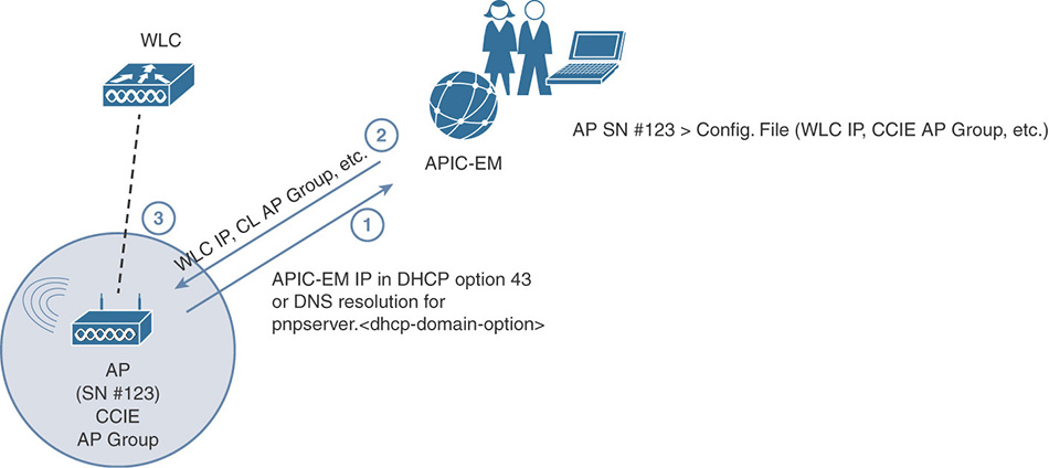
As shown in the workflow of Figure 4-11, instead of the “classic” WLC discovery and join process through DHCP option 43 or DNS resolution, APs could also discover and join the APIC-EM server instead. An AP declared in APIC-EM through its serial number and model can download an associated configuration file, which contains the WLC’s IP for the standard registration process, but also other parameters, such as the AP Group, secondary and tertiary WLC’s information, the FlexConnect Group, and so on. The goal of this solution is to automate the deployment of some AP’s parameters instead of waiting for the AP to join the WLC before configuring them. As a side option, this workflow allows you to define a list of APs and associate them with a configuration file, which among other things is used to discover and join the WLC. APs not declared in APIC-EM and still able to discover it are put in a claim list, where they stay until moved to a different one. The claim list is not associated to any configuration file, so APs in that list will not be able to download any setting to join a WLC. Although not necessarily the primary use case for which APIC-EM PnP was designed, this feature could be used as an approval or authorization process for APs.
AP Modes of Operations
After connecting successfully to the network, lightweight APs can automatically discover and register to a WLC through different options, such as broadcast, DHCP, DNS, or other discovery techniques. Although this is a fundamental process, we will not cover it in this book in depth because a very well detailed description is already available in the official “Enterprise Mobility 8.1 Design Guide”:
An out-of-the-box AP by default will join a WLC in the so called “local” mode. As discussed at the beginning of this chapter, the local mode allows the AP to switch all the wireless clients’ traffic centrally through the WLC, which will bridge this very same traffic to specific VLANs if needed. As a general rule, the local mode is the one that supports the broadest spectrum of features. To change the AP mode you have the following options:
After the AP joins the WLC: This is the most classic approach, and you can modify the AP mode either through the WLC’s GUI/CLI or even with an external management tool for multiple APs at the same time, such as with Cisco Prime Infrastructure, via SNMP.
To change the AP mode through the WLC’s GUI, as shown in Figure 4-12, you can browse under WIRELESS > Access Points > All APs and click the AP of your choice.
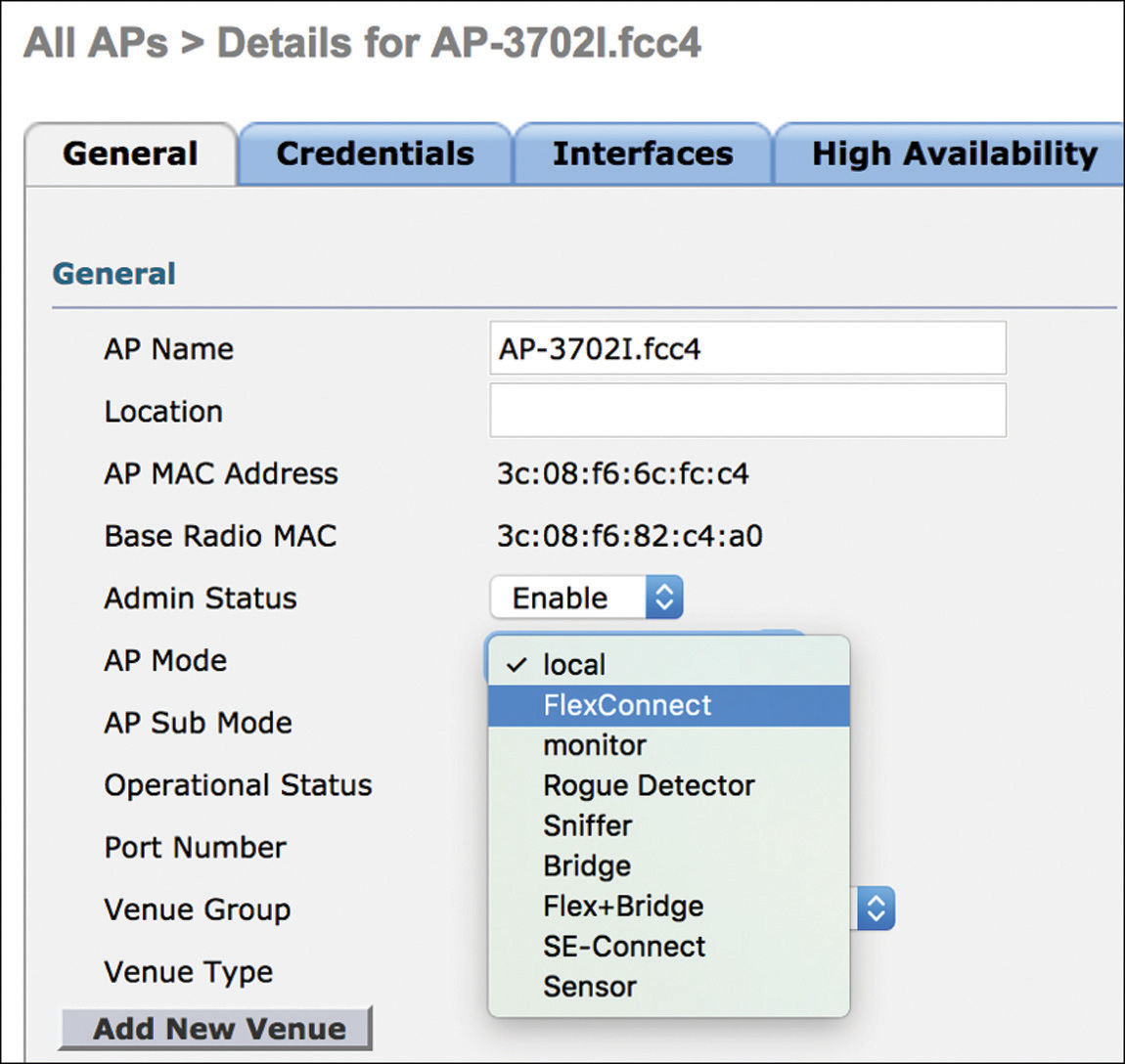
Figure 4-12 AP Mode Configuration Example Through the WLC’s GUI Before the AP joins the WLC: Through the APIC-EM PnP solution described in the previous section, an AP could download a configuration file with its operating mode before joining the WLC. In this case, the AP mode you can push beforehand is the FlexConnect one.
Automatically, when the AP joins the WLC: You can configure the WLC to automatically convert APs joining it to either FlexConnect or Monitor mode, through the following command line:
config ap autoconvert [disable | FlexConnect | monitor]
This option is not available via GUI and is supported on the following controller models: 7510, 8510, 5520, 8540, vWLC.
FlexConnect is the mode to switch traffic locally, at the AP’s level, and bridge it directly on a VLAN of the switch port, where the AP is connected. This mode also adds some “survivability” options to the AP: if connectivity to the WLC is lost, locally switched clients already connected to a WLAN can stay connected, at least until the next (re)association, and new clients can connect under some conditions. To switch clients locally, on top of the AP in FlexConnect mode, you need to enable FlexConnect Local Switching on the wanted WLAN too.
Since AireOS 8.2, when changing the AP mode from local to FlexConnect, the AP does not need to reboot anymore. Other changes in the AP mode, for example from FlexConnect back to local or any other combination, require the AP to reboot.
Monitor mode is another option that has been available for many years to set the AP in a “listening” operational status. An AP in monitor mode does not serve any wireless client and keeps cycling through different wireless channels to scan for rogue APs, attacks, RRM stats (such as Channel Utilization), and interferences (if supported by the AP model).
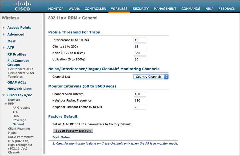
Channels, which a monitor mode AP should cycle through, can be just those allowed for Dynamic Channel Assignment (DCA), those allowed by the Country code configured for the AP, or all channels. As shown in Figure 4-13, you can configure this for the 2.4 GHz or 5 GHz band under WIRELESS > 802.11a/n/ac or 802.11b/g/n > RRM > General. This setting applies to all AP operational modes, not just to monitor mode APs.
Saying that monitor mode APs are solely for monitoring purposes would not be 100% accurate: they also support containment actions when rogue APs are detected (more on this in the next sections).
To detect whether a rogue AP is connected to a specific subnet/VLAN on your wired network, you can deploy APs in Rogue Detector mode. A rogue detector AP has its radios disabled, and through its Ethernet interface it listens for ARP messages from rogue APs or rogue clients. If a MAC address from a rogue AP/client, plus or minus 1 in the last right-most byte, is seen in ARP messages on the wired network, it means that the specific rogue AP has access to one of the VLANs monitored by the rogue detector AP. More details on rogue detection techniques and options are available in one of the next subsections of this chapter.
The rogue detector mode is not supported on COS APs.
Mainly for troubleshooting purposes, an AP can also act as a remote sniffer, from which you can collect a wireless trace directly on your machine. This is the purpose of the Sniffer mode. After changing the AP mode to Sniffer and waiting for the AP to reboot, under the configuration of each AP’s radio you will see an option for Sniffer Channel Assignment (WIRELESS > Access Points > Radios > 802.11a/n/ac or 802.11b/g/n and then by selecting the sniffer AP). Here you can specify the main channel (for channel widths greater than 20 MHz) to sniff for taking the wireless trace, as well as the server IP address, which is the IP of your machine, where tools such as Wireshark or OmniPeek should be running. The trace is collected by the AP and centrally forwarded to the WLC, which will in turn send it to the configured server IP address. You will receive the trace on your machine sourced from the WLC’s management IP, as UDP traffic from port 5555 and with UDP port 5000 as destination. All the details on how to configure an AP in Sniffer mode and capture a trace through Wireshark or OmniPeek are available in the official document “Fundamentals of 802.11 Wireless Sniffing”:
Note
If Air Time Fairness (ATF) is enabled, trying to change the AP mode to Sniffer (or some other modes too) might fail. On the WLC’s GUI you may see no warning/error messages and on the CLI you should see a message similar to the following:
(Cisco Controller) >config ap mode sniffer <AP_Name>

Changing the AP's mode will cause the AP to reboot.
Are you sure you want to continue? (y/n) y
Unable to set AP in this mode. Air Time Fairness needs to be disabled.
To prevent this, you can disable ATF globally through the following commands:
(Cisco Controller) >config atf 802.11a mode disable

(Cisco Controller) >config atf 802.11b mode disable
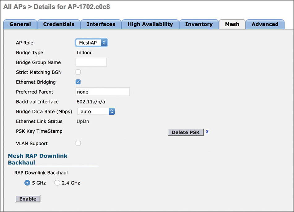
For mesh deployments, the dedicated AP mode is Bridge. When you configure the Bridge mode, the AP by default reboots as a Mesh AP (MAP) and tries to register to the WLC via the radio backhaul or the wired backhaul, if its Ethernet interface is connected. You can modify the mesh mode to Root AP (RAP), for example, under the Mesh tab settings of the AP, as shown in Figure 4-14, which become available after configuring the Bridge mode itself.
Mesh is used to interconnect APs through a wireless backhaul instead of a standard wired Ethernet one. At least one AP, called the Root AP, must have wired connectivity to forward traffic to the uplink backend network. Other APs without wired connectivity can associate to the Root AP (or between them) via either the 5 GHz band (the default behavior) or the 2.4 GHz one, and use this radio link as their uplink to the rest of the network. These APs are referred to as Mesh APs in the WLC. Although technically all APs can communicate with each other for calculating and building the mesh backhaul, at any specific point in time an AP won’t be communicating with all other APs at the same time. Mesh APs negotiate an optimized “path” to the Root AP, and recalculate such a path dynamically if conditions change (for instance, a MAP becomes unavailable, a DFS event is triggered, an interference occurs, and so on). Because of this capacity of all APs communicating with one another, the term mesh is used.
Although mesh deployments are often associated with APs installed outdoors, wireless mesh networks are used indoors, too, where Ethernet cables cannot be pulled to provide wired backhaul connectivity (warehouses, storage depots, manufacturing facilities, and so on). The Bridge mode is supported on indoor/outdoor IOS APs and on outdoor COS APs (for example, the 1540 and 1560 series APs). At the time of this book’s writing and for AireOS 8.3, the Bridge mode and mesh options are not supported on indoor COS APs (1800/2800/3800 series APs).
Traffic from wireless clients associated to mesh APs in Bridge mode is centrally switched through the WLC. Communications between MAPs, as well as between MAPs and RAPs, are encrypted through AES. Client’s data traffic is encapsulated in CAPWAP and carried over the air within the mesh header. After reaching the RAP, the CAPWAP-encapsulated client’s data traffic is carried all the way up to the WLC, as for a standard AP in local mode, for example. The WLC then bridges the client’s traffic on the VLAN of the corresponding dynamic interface.
Note
Although detailed in one of the next sections focusing on mesh architectures, we prefer to already quickly distinguish the switching model for wireless clients from the one for wired clients connected behind a RAP/MAP. Some AP models in Bridge mode (or Flex+Bridge) support connecting wired clients to a dedicated, auxiliary Ethernet port on the AP. This feature is also referred to as Ethernet Bridging. Wired clients behind a MAP/RAP are locally switched at the RAP’s level, on a VLAN of the switch port’s trunk, where the RAP is connected; these wired clients are not centrally switched all the way up through the WLC.
Quite close to the FlexConnect, mesh APs can also be deployed in Flex+Bridge mode. With this option, wireless clients’ traffic is locally switched at the RAP’s level, on a VLAN of the switch port’s trunk, where the RAP itself is connected. As with FlexConnect, the Flex+Bridge mode provides some additional survivability features: If the uplink connectivity with the WLC is lost, clients associated to Flex+Bridge mesh APs, and to a FlexConnect Local Switching enabled WLAN, keep being locally switched at the RAP’s level, without losing connectivity. All other mesh principles for communications between MAPs, and between MAPs and RAPs, stay the same, as for the more “classic” Bridge mode.
For spectrum monitoring and troubleshooting purposes, the Spectrum Expert Connect (SE-Connect) mode configures an AP into some sort of remote antenna, supporting physical layer visibility of wireless frequencies through a spectrum analysis tool installed on your PC. You can configure the SE-Connect mode only on APs supporting the CleanAir technology (2700, 3700, 2800, 3800 series APs), which is based on a dedicated radio chipset for inline monitoring of 802.11 frequencies, as well as interference detection and classification. CleanAir is the Cisco rebranding of the former Cognio solution, acquired in 2007 and integrated in the APs portfolio since 2010. Cognio Spectrum Expert was the original name of the tool used to connect to Cognio antennas for spectrum analysis: Cisco still provides a similar tool, under the name of Cisco Spectrum Expert, available for up to Windows 7 operating systems:
For machines with newer Windows operating systems, you would need to use the Metageek Chanalyzer tool to connect to an AP in SE-Connect mode:
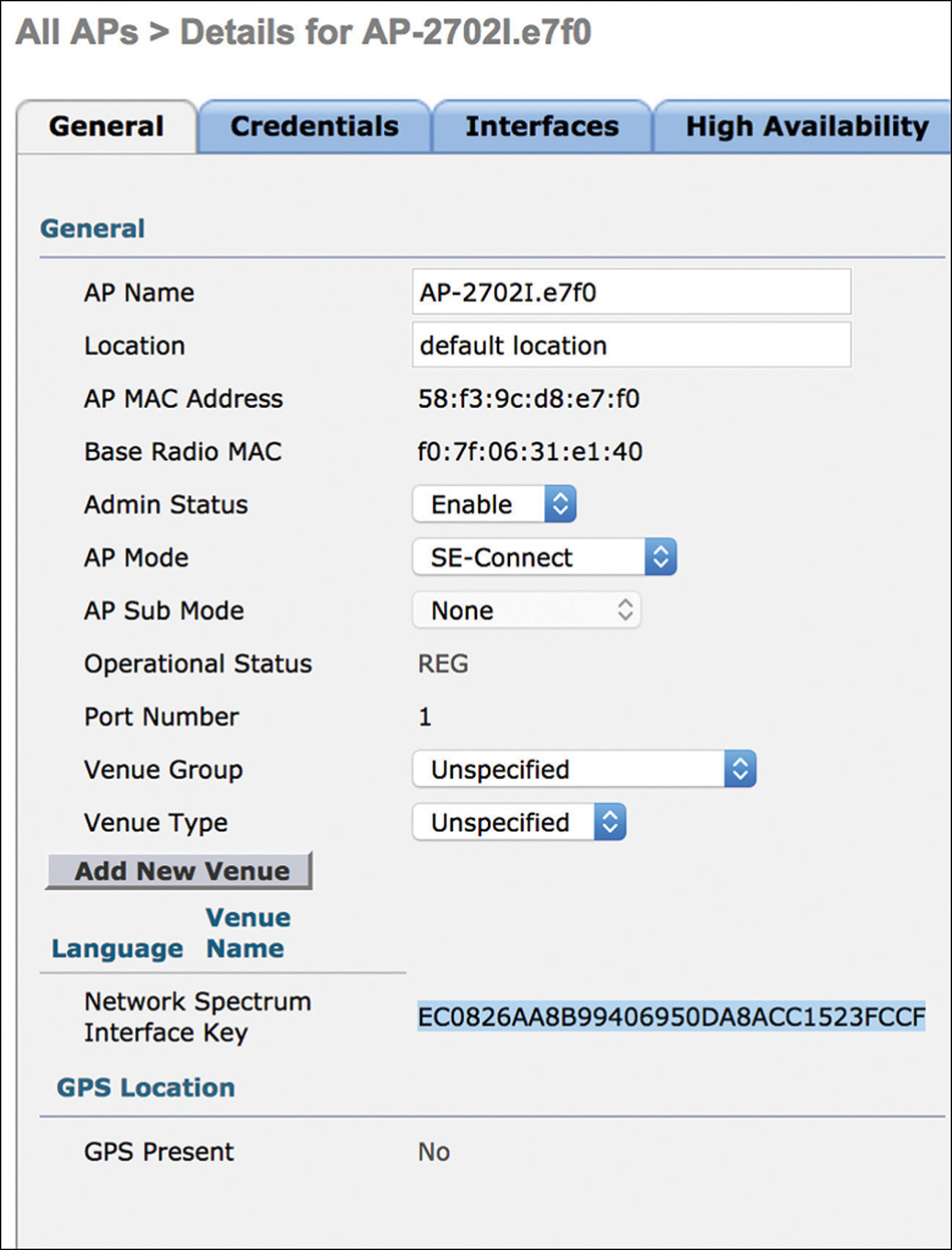
An SE-Connect AP does not serve wireless clients and monitors the full spectrum of 802.11 frequencies, both in the 2.4 GHz and 5 GHz bands. To communicate with an SE-Connect AP, the Cisco Spectrum Expert or the Metageek Chanalyzer tools need the AP’s IP and a key, which is visible under the AP’s general details, as shown in Figure 4-15.
If you already worked with APs in local or Monitor mode before, you may have noticed that such a key is available under these modes too. Local or Monitor mode APs integrating the CleanAir technology also support spectrum visibility and analysis through the Cisco Spectrum Expert or Metageek Chanalyzer tools. Local mode APs provide spectrum visibility just for the channel where they are serving clients. Monitor mode APs support spectrum visibility for all 802.11 frequencies.
So what are the differences between Monitor mode and SE-Connect mode for spectrum analysis purposes? Technically, not too many. SE-Connect was originally developed as the only mode to allow connectivity to a CleanAir-capable AP with a remote spectrum analysis tool, and at that time local and Monitor modes didn’t support such a feature. Subsequent AireOS versions implemented support for connecting to a CleanAir-capable AP with a remote spectrum analysis tool even with an AP in local or Monitor mode. The Monitor mode scans all frequencies and supports spectrum analysis; it technically does not differ too much from the SE-Connect mode. However, SE-Connect, having been designed from the beginning for the sole purpose of spectrum analysis with a remote tool, goes through some slightly more scanning periods (that is, dwells) as compared to the Monitor mode. For the best troubleshooting options, it is still recommended to use the SE-Connect mode.
Accessing Configuration Settings and Logging Options for APs
Lightweight APs are mainly managed through the WLC, which is the device pushing the vast majority of the configuration parameters. You can still configure some settings on the APs directly via CLI, mainly for options such as a static IP, or even primary, secondary, and tertiary WLC IPs. As seen in the previous subsection, 802.1X credentials can also be configured via CLI on the AP directly. To generalize these concepts a bit more, we could say that the AP’s CLI provides you with the needed commands to manually connect an AP to the network and register it to the WLC.
All the details on other useful commands for a lightweight AP’s CLI are documented in the official “Cisco Wireless Controller Command Reference”:
IOS-based lightweight APs still allow you to access all the CLI commands available for autonomous APs. You can achieve this through the command debug capwap console cli in enable mode (the command is hidden, so autocomplete through the tab key does not apply). From here, you could theoretically use any other command available for autonomous IOS APs. On top of not being officially recommended or supported, commands for the autonomous mode applied in lightweight mode through this technique do not survive a hardware reset of the AP. Thanks to this option you can still force some operations, such as a reimage, an upgrade, or even a conversion of the AP from lightweight to autonomous. The following command sequence shows an example of how to push a new image file for these use cases:
ap# debug capwap console cli
ap# archive download-sw /force-reload /overwrite tftp://TFTP_Server_
  IP/Image_File_Path
Note
COS APs do not support the debug capwap console cli command because there are no IOS commands or autonomous mode for these APs.
The WLC pushes all other AP’s parameters for nominal wireless operations. All features that you can configure through the WLC’s GUI are available via CLI too. The reverse is not always true, because some CLI commands do not have an equivalent in the WLC’s GUI (for example, the management via the dynamic interface setting that we saw in one of the previous sections).
The main menus and commands affecting the AP’s settings and behavior are under the WLANs and the WIRELESS tabs. Under WLANs you can create wireless networks but also assign APs to AP groups. Under the WIRELESS tab you have access to even more specific options, on a per-AP basis, as well as on a more global level.
By browsing to the details of an AP under WIRELESS > Access Points > All APs and clicking the wanted AP, you can access different tabs to set the operational mode (for example, local, FlexConnect, Bridge, and so on), the credentials, primary/secondary/tertiary controllers’ coordinates, FlexConnect/Mesh related parameters (if the AP is in FlexConnect/Bridge mode), and so on. Settings applied through these tabs, directly at the AP level, override those that you could push through FlexConnect groups, or other logical groups, for example. The WIRELESS section also provides access to all the radio settings, again either on a per-AP basis, at the AP group level through RF profiles, or even at a more global level for all APs. Other main features available under the WIRELESS tab include advanced RF management (for example, Flexible Radio Assignment, Rx SOP, optimized roaming), Mesh, Application Visibility and Control (AVC), or even QoS. Because this book is more focused on theory of operations, and because configuration details are reserved to the Wireless CCIE lab, we explicitly decided to leave those to the official “Cisco Wireless Controller Configuration Guide”:
and the “Enterprise Mobility 8.1 Design Guide”:
On top of configuring AP’s features, you may want to consider additional logging options for sending syslog messages. An AP not yet registered to a WLC by default sends syslog messages to the broadcast IP 255.255.255.255. It is usually a good practice to dynamically assign a syslog server to your APs through the DHCP option 7. This could, for example, prevent an overload of broadcast messages if many APs are deployed on the same subnet/VLAN. When an AP joins the WLC, the syslog configuration on the WLC, if any, overrides the one received via DHCP option on the AP. On the WLC you can configure a syslog server, for all APs or for a specific AP, with the following commands:
config ap logging syslog facility {facility name}
config ap logging syslog level {syslog level}
config ap syslog host global {server IP} (for all APs)
config ap syslog host specific {AP name} {server IP} (for a specific AP)
Facilities are used in syslog messages to identify which process generated the corresponding messages. For the purpose of simply sending logs from a device, there is technically no wrong choice among the many facilities. You could think of the facility as a “tag” or additional information in the syslog message to recognize the source process, or the device, sending that message. Their main goal is therefore to allow you better organizing messages on the syslog server itself, so that you can, for example, filter all logs from the same source/process/device thanks to a specific facility level.
Through the syslog level, on the other hand, you decide which categories of syslog messages are sent (Critical, Warnings, Informational, Debugging, and so on). When you set a specific level, messages belonging to all other lower levels are automatically sent too. For example, the Warnings level will also cause logs in the Critical level to be sent. If for troubleshooting purposes you had to enable the Debugging level, for example, it is usually recommended to lower the level back to a less verbose one after the troubleshooting phase, so as not to overflow your syslog server with additional messages when not needed anymore.
From the WLC, you can also view the event logs from an AP directly with the command show ap eventlog {AP name}.
For logs from the WLC itself, you can access similar settings directly through the GUI, under MANAGEMENT > Logs > Config, or else through the CLI with the config logging [...] command options.
High Availability and Redundancy
Along with planning and deploying your wireless network, as a Wi-Fi expert you may often be questioned about how to make that network redundant. We could approach high availability needs from different sides and through different options: on the radios, on the APs, on the controllers, and so on.
As a first option, and because this is most likely happening during the initial radio design phase, you could consider planning for a redundant radio frequency (RF) coverage/capacity. When simulating and verifying your site survey with tools, such as Ekahau or Airmagnet, you could plan coverage areas and APs placements, so that at each point on the map the second loudest AP should still be heard with a signal strength powerful enough to keep serving clients, if the main loudest AP at that same point of the map would fail. Figure 4-16 shows an example of the options for displaying the coverage of the second strongest APs in Ekahau.
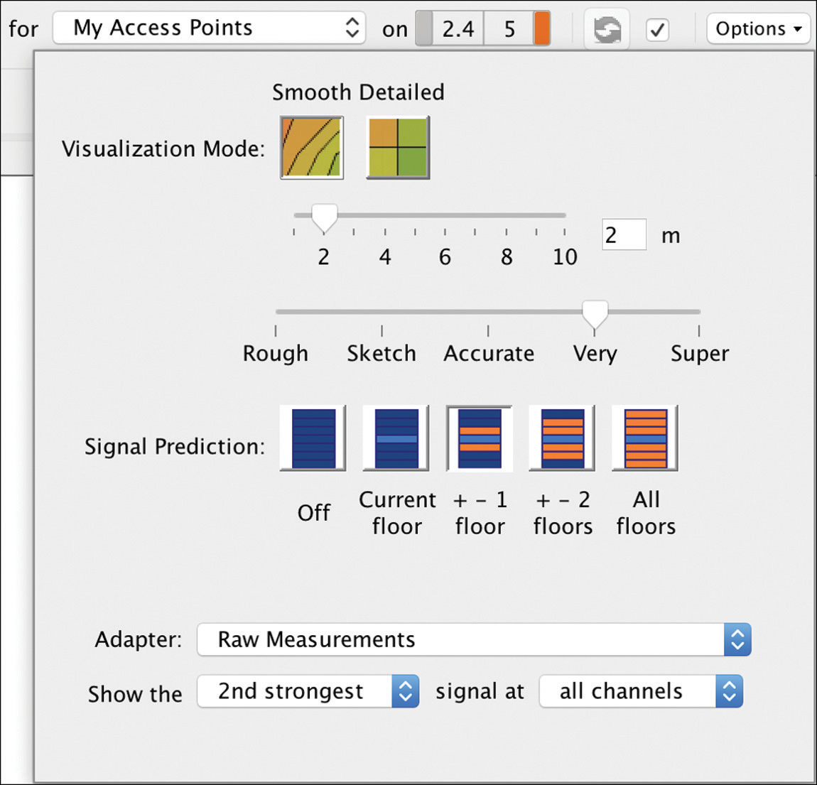
Cisco provides software-based features in the WLC, through Radio Resource Management (RRM) algorithms, to allow APs to increase their transmit power levels when they identify a coverage hole. The rules under which a coverage hole event is triggered depend on many factors, and the WLC might not necessarily always increase the transmit power of an AP, if that would cause co-channel interferences with other APs, for example. For such reasons, on top of relying on RRM’s coverage hole detection in software, you may want to consider planning for radio redundancy right from the beginning, during the initial site survey phase.
At the AP’s level itself, some models present an auxiliary Ethernet port. However, such an additional interface can be used for increased bandwidth but not for uplink high availability. On the 1850/2800/3800 series APs you can configure link aggregation when these APs are in local mode:
The goal of the auxiliary port on these latest AP models addresses the additional bandwidth requirements introduced by the 802.11ac Wave 2 certification. Nevertheless, for uplink connectivity and PoE+ powering options, the “standard” primary Ethernet port must always be connected anyway.
Note
Previous AP generations (1700 and 2700 series) have an auxiliary Ethernet port, although not for increased bandwidth purposes. The auxiliary port for 1700/2700 APs is supported to bridge a wired client on the same subnet/VLAN as for the uplink Ethernet interface of the AP.
Redundancy when planning for RF coverage during the site survey, as described in the aforementioned paragraphs, could be seen as some kind of high availability for APs, where one AP can cover another AP’s cell in case of failure.
We already detailed redundancy for the WLC’s ports when describing its interfaces and link aggregation options. In the following paragraphs we address high availability options more in terms of primary, secondary, and tertiary WLCs, or active and standby controllers.
For pure FlexConnect deployments, APs already provide some survivability in case the WLC is unavailable. Although you could lose the possibility to push configuration changes, already connected clients in FlexConnect local switching are not affected by the loss of the WLC. Sometimes this is acceptable for some deployments, for which WLCs redundancy might become less structural than for centrally switched wireless networks, for instance.
N+1 and N+N High Availability
The more legacy high availability (HA) model for WLCs is what has often been referred to as N+1, or even also N+N. We could generalize it as N+X, with X greater than or equal to 1 (and usually less than or equal to N, although technically not necessary). The first N refers to your primary WLCs, among which you distribute your lightweight APs. The second digit after the plus sign (1, N, or another X) represents the number of secondary controllers ready to take over the APs from one or more of the primary WLC(s) in case of failure.
This notation is mainly used to indicate the number of backup controllers, and sometimes we just keep the first N as is, without necessarily specifying the number of primary controllers. We could, for example, state that we deployed 3+2 controllers to say that there are 3 primary and 2 secondary WLCs. Or we could also say that we deployed 3 controllers with an N+2 HA model, as a “synonym” to describe that there are 2 secondary controllers for backup.
You may want to achieve redundancy with an N+1, an N+2, or an N+3 or more HA model. There is not necessarily a fixed rule for how many secondary controllers you should deploy. To push this concept a bit further, we could, for instance, have just one 5508 WLC as primary with four 2504s as secondary WLCs, and we would talk about a 1+4 HA model. Point taken, this might not be one of the most common scenarios; we just used an exception as a further example of the theory.
Sometimes, if tertiary controllers are deployed, we could even start using the N+X+Y notation: for example, N+1+1 would indicate that we deployed a secondary and a tertiary WLC, N+3+2 would describe a deployment with three secondary and two tertiary WLCs, and so on.
The two most common N+X HA models are the N+1 and N+N. The former indicate that we have just one WLC as secondary for all the other primary WLCs. The latter is used for deployments, where we have as many secondary WLCs as the number of primary ones. With N+1 HA, because there is just one secondary WLC, you might need to “sacrifice” some APs in case all your primary WLCs fail and the secondary one does not scale enough to take over all APs. However, if you deployed one, big, fat WLC as secondary for one or more “smaller” WLCs, the N+1 HA model could still provide full redundancy. An example is a deployment with four 5508s as primary WLCs and an 8510 or an 8540 as secondary, in an N+1 HA model. An 8510 or an 8540 WLC can support up to 6000 APs, hence scaling high enough to take over the full load from four 5508s (or even more).
In an N+1 or N+N HA deployment all WLCs are active. Originally, you didn’t have to enable a specific feature to tell a WLC that it was primary, secondary, or tertiary. It’s at the AP’s level that we point the AP to one WLC or another. More recently this notion changed a little bit at the WLC’s level, and we will see how in the next paragraphs, because this also involves a more recent licensing model.
APs are configured with primary, secondary, and even tertiary WLCs if needed. A primary WLC for some APs could be the secondary or the tertiary for some others. Take, for instance, two primary WLCs with just one backup WLC, as in an N+1 HA deployment; we’ll call WLC-1 and WLC-2 the primary WLCs and WLC-3 the backup one. Some APs could point to WLC-1 as primary, WLC-2 as secondary, and WLC-3 as tertiary. Some other APs could point to WLC-2 as primary, WLC-1 as secondary, and WLC-3 as tertiary. This example works under the assumption that WLC-1 and WLC-2 would both have enough licenses to support at least some or even all the APs from one another. But this is actually not 100% true if we take into account the Smart Licensing feature introduced as of AireOS 8.2, although for 5520 and 8540 WLCs only (and the 3504 WLC too, starting from the even more recent AireOS 8.5):
By activating the Smart Licensing solution, you configure the WLC to communicate with servers hosted on the Cisco cloud, which keep track of the licenses you bought, to use them in some kind of license pool fashion. Each WLC using Smart Licensing will communicate with your account on the Cisco cloud and update the license counter when an AP registers or deregisters. If your WLCs start asking for more licenses than what are allocated, Smart Licensing does not block any new AP from registering. By default, an AP is always accepted by a WLC up to its HW limit (1500 APs for the 5520 WLC and 6000 APs for the 8540 WLC), and the license counter is updated accordingly. If your WLCs have more APs than the number of licenses bought and available on your Smart Licensing account, a warning message is displayed, but again, APs won’t be denied from registering to a WLC. This solution allows buying licenses for the exact number of APs you are deploying, and configure primary, secondary, and tertiary controllers without worrying about installing extra licenses, which might not be used all the time.
Even before the release of Smart Licensing on more recent WLC generations, as of AireOS 7.4, Cisco introduced the AP and then the Client Stateful Switch Over (SSO) feature, as well as high availability controller models (or HA stock keeping units [SKU]) for their appliance-based WLCs. SSO is detailed in the next section, but if we focus on N+1 HA for now, we can already see how HA WLC models play a role as secondary or tertiary controllers too. An HA SKU controller (for example, AIR-CT5508-HA-K9, AIR-CT8510-HA-K9, AIR-CT7510-HA-K9, and AIR-CT2504-HA-K9) accepts any number of APs up to its HW limit, without the need to install any AP license. This means that you can deploy an HA SKU controller as secondary (or even tertiary) WLC at no additional license cost. It also turns out that any “standard” WLC model can be used as an HA SKU, because high availability features are in the end purely based on a software configuration and not necessarily tied to specific hardware models. An HA SKU controller is shipped ready to accept APs up to its HW limit; a regular WLC can be configured to accept APs up to its HW limit through the SSO redundancy options under CONTROLLER > Redundancy > Global Configuration, as shown in Figure 4-17, by setting the option Redundant Unit to Secondary (the option SSO should stay Disabled).
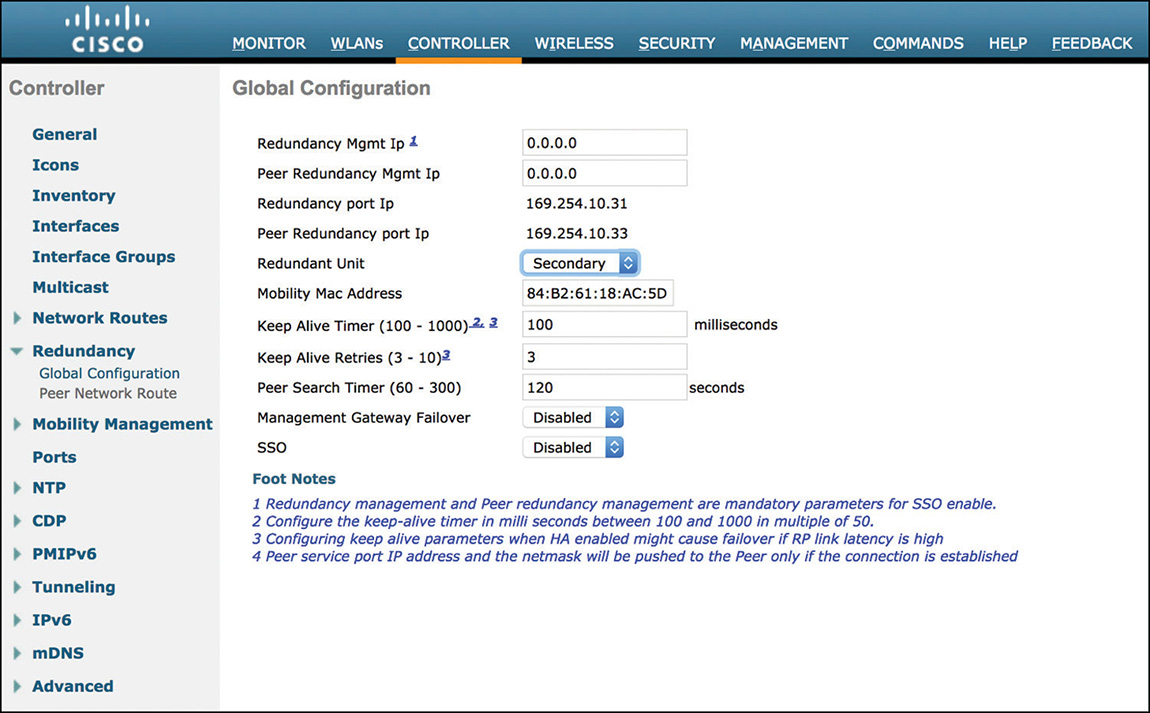
Note
A standard 5508 WLC must have at least 50 AP licenses to be converted into an HA controller. Similarly, a 2504 WLC must have at least 25 AP licenses.
An HA SKU controller, or a standard WLC converted to HA, is ready to accept as many APs as its HW limit, but that should not last longer than 90 days. After 90 days, no feature ceases to work. All WLC functionalities keep running and APs can still register. The WLC, however, starts logging console and syslog messages about the fact that the 90-day period has expired. An HA WLC should be used as a secondary/tertiary controller, not as a primary one: the assumption is that after those 90 days the APs should have reverted back to their primary WLC(s), for example, because reachability has been reestablished or because a replacement has been provided in case of an HW failure. An HA WLC does not know whether it is being used as secondary or tertiary, so you can point APs to HA WLCs as either secondary or tertiary. Although technically possible because no features are blocked, you should not use an HA WLC as primary; otherwise, you would be running an officially unsupported scenario, and Cisco might refuse to provide technical assistance. As a further note, an HA SKU controller can be turned into a standard WLC, under CONTROLLER > General, by setting the option HA SKU Secondary Unit to Disabled. From this point you can use the HA SKU WLC as any other standard WLC, keeping in mind that by default it will have no AP licenses.
If we now consider again an N+1 deployment, we could, for example, have the N primary controllers either running local licenses or using the Smart Licensing pooling solution, while the one secondary controller could be an HA WLC accepting as many APs as its HW limit up to a period of 90 days. The same would apply to an N+N deployment, with N secondary HA WLCs.
In the past, for APs to switch between primary, secondary, and tertiary controllers, all WLCs needed to share the same virtual interface IP address and the same mobility group name. More precisely, every WLC must be declared in each other’s mobility domain, with the same mobility group name, under CONTROLLER > Mobility Management > Mobility Groups. On top of that option, nowadays you can also just configure APs with the controllers’ names and IPs under each AP’s High Availability options to support failover even without having those WLCs in the same mobility group.
To clarify the terminology, the mobility domain of a WLC is the list of its other WLC peers under CONTROLLER > Mobility Management > Mobility Groups, with or without the same value for the mobility group under the column Group Name. The mobility group is a string value, a name, identifying precisely the mobility group of a WLC. Again, to support APs’ failover between WLCs without configuring those WLCs’ IPs under the APs’ High Availability options, those WLCs must all be declared in each other’s mobility domain, with the same mobility group name. The same holds true for key reuse of clients roaming between different controllers (inter-controller roaming): WLCs must be in each other’s mobility domain, with the same mobility group name. For other scenarios, such as guest anchoring, for a foreign WLC to tunnel traffic for a specific WLAN to an anchor WLC, WLCs must be in each other’s mobility domain, but they do not need to share the same mobility group name.
Note
The WLC’s GUI, under CONTROLLER > General, allows you to configure what it calls the Default Mobility Domain Name. Although this may seem confusing, this field sets the WLC’s mobility group name.
You can configure primary, secondary, and tertiary WLCs for an AP through the WLC GUI, under WIRELESS > Access Points > All APs, by clicking the wanted AP and browsing to its High Availability tab. To industrialize the process, you can also push high availability settings to multiple APs at once through Cisco Prime Infrastructure. One more option could also be the Plug-and-Play solution with APIC-EM, as described in a previous section.
One of the main advantages of the N+1/N+N HA model is that controllers can be separated across L3 boundaries; hence their management IPs do not need to reside on the same subnet/VLAN. On the other side, when an AP switches from one WLC to another, it needs to reregister to the new WLC. One of the main consequences is that the clients are disconnected and need to go through a full association again with the new WLC (in fact, there is a period of downtime between primary WLC failure and the time it takes for the AP to reregister with the backup WLC).
For any additional configuration details on N+1 HA, you can also refer to the official “N+1 High Availability Deployment Guide”:
Note that N+1 or N+N redundancy (and AP/Client SSO) is not supported with vWLCs until AireOS 8.4.
Mobility Express does not support mobility groups, hence no notion of N+1/N+N or SSO redundancy. However, as mentioned in the previous section introducing Mobility Express, VRRP is used to ensure high availability for this type of deployment.
AP and Client Stateful Switch Over
Cisco was the first vendor on the market to introduce full stateful redundancy features for both APs and clients. AireOS 7.3 supported the initial version of stateful switch over (SSO) for APs, and AireOS 7.5 started supporting SSO for clients too.
SSO is configured between two controllers only, one acting as primary/active and the other as secondary/standby. The term stateful points to the fact that an AP’s or client’s session is fully replicated from the active to the standby WLC. In case of failover, the standby WLC is ready to seamlessly take over APs and clients with almost no interruption in their communications. We carefully use the adverb “almost” here, because clients may experience some minor latency for some traffic categories. Nevertheless, no connectivity is lost: APs do not need to register again and clients must not reassociate, reauthenticate, or go through DHCP again to obtain a new IP address. This solution presents major benefits for APs and wireless clients, but it also contributes to not overload network services behind the WLCs in case of a failover. Because APs and clients do not need to go through registration, authentication, or even DHCP again, for example, those network services do not risk being called into play all of a sudden and for many APs/clients concurrently. For instance, RADIUS servers do not need to reauthenticate all wireless clients at once because a WLC failed and those clients had to reconnect altogether.
Sometime we also refer to the active and standby WLCs as a “pair.” When configured for SSO, the two controllers share the same management IP and are seen by the rest of the network as one single device.
AP/Client SSO has been enhanced with additional features through different AireOS versions; you can find all the details of such functionalities in the official “High Availability (SSO) Deployment Guide”:
We will hereafter list some of the main characteristics of AP/Client SSO, while leaving all other configuration details to the aforementioned official guide:
Controllers of an SSO pair need to be of the same HW models among the following: 5500, 7500, 8500, and WiSM2 series WLCs. The more recent 3504 series WLC supports AP/Client SSO too.
Round trip time (RTT) latency between management IPs of the active and standby WLC should not exceed 80 milliseconds by default.
The bandwidth between the two controllers should be of at least 60 Mbps.
Only sessions for connected clients in the RUN state are synchronized between active and standby WLCs, and as of AireOS 8.0, the sleeping client cache is replicated too. Clients in other states (for example, 802.1X_REQD, DHCP_REQD) have to go through a new association in case of failover.
You must configure the management IPs from both the active and standby WLC on the same subnet/VLAN for SSO to be supported.
The choice between keeping the controllers on the same Layer 2 or separating them across Layer 3 boundaries could sometimes be one of the main decision factors when evaluating the N+1 HA model or SSO.
SSO requires the two controllers to communicate through an additional dedicated port, called the Redundancy Port (RP), as well as to create another logical interface, called the Redundancy Management Interface (RMI), on the same subnet/VLAN as the regular management interface.
For SSO to work, you must reserve four IP addresses in the management subnet/VLAN: two IPs for each WLC’s management interface and two IPs for their corresponding RMIs. The SSO configuration process assigns autogenerated IPs in the 169.254.X.Y format to the redundancy ports, which also have to be connected on the same VLAN (when using switches between RPs; normally, they are directly connected without switches in between). This VLAN associated to the RPs, however, needs to exist just to allow the RPs from the two WLCs to communicate and does not have to be propagated anywhere else: it must not be the same VLAN as the management and RMI interfaces, and should be pruned from their corresponding ports if possible.
AP/Client SSO represents nowadays the most common high availability model, with even more deployments than the “legacy” N+1 HA. New installations, where the requirement for WLCs on the same subnet/VLAN can be introduced from the beginning, implement AP/Client SSO more often because of the reduced downtime in case of failover.
Segmenting Your Wireless Network
The term segmentation can have several applications, but in this specific section we will use it in the context of separating radio settings, network parameters, and features between different groups of APs.
RF Profiles
The first tool you may consider to assign different radio settings to different sets of APs are RF profiles. They were introduced as of AireOS 7.2 with the purpose of differentiating RRM parameters on a per AP Group basis.
You can configure RF profiles under WIRELESS > RF Profiles, where you might already see that some default profiles are already automatically created for low, typical, or high client density.
When creating a new RF profile, you first need to choose whether it applies to the 2.4 GHz or the 5 GHz radio, and then you can optionally make it inherit settings from one of those pre-canned profiles. Each profile allows customizing parameters for data rates, RRM algorithms, high density features, and client load balancing options, as shown in Figure 4-18.
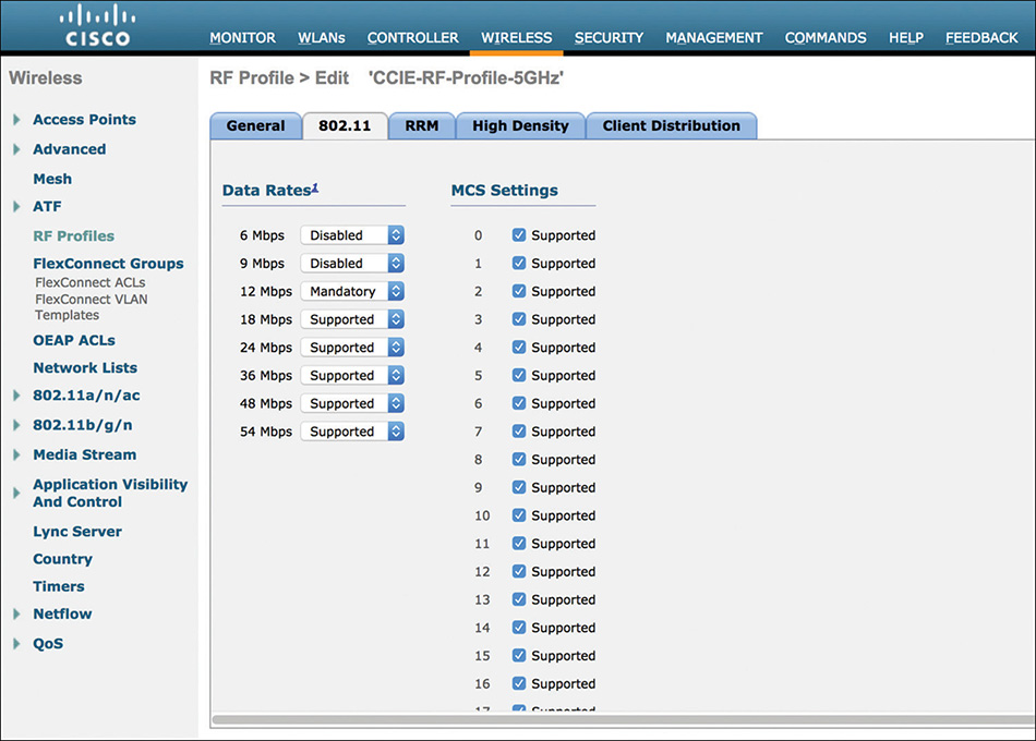
By assigning an RF profile with all data rates disabled for a specific 802.11 band, for example, you can kind of “disable” that band on a distinct set of APs. In a similar way, you could influence throughput, coverage zones, or even roaming behaviors for clients of a specific area or site. A typical use case for segmenting RRM configuration by AP groups could be to assign different sets of channels to some other areas of your deployment. This may be required if those zones cannot operate on specific frequencies, or if some channels need to be reserved for particular devices and use cases. In other situations you might have to tweak settings for transmit power control (TPC) calculations so that certain APs do not lower their power level below a given threshold. This could be the case for APs installed on higher ceilings, which should keep a minimum signal stronger than APs mounted at more standard heights.
High-density options under an RF profile, such as the Receiver Start of Packet (Rx SOP) threshold, let you push the configuration for customized receiver “sensitivity” to some APs only.
After creating an RF profile, you need to assign it to an AP group for its settings to take effect on the wanted APs. Each AP group’s configuration menu has a dedicated RF Profile tab, as shown in Figure 4-19, where you can assign a profile for the 802.11a (that is, the 5 GHz) band and/or another profile for the 802.11b (that is, the 2.4 GHz) band.
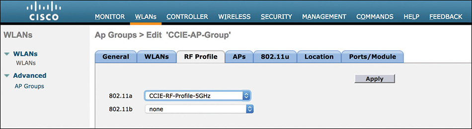
AP Groups
As seen in the previous paragraphs, AP groups are tightly related to RF profiles because you apply those profiles under the AP groups’ configuration directly. However, AP groups were originally introduced to customize some WLAN settings for specific sets of APs. You can access them under WLANs > Advanced > AP Groups in the WLC’s GUI.
A default AP group is always present in the WLC’s configuration: all APs are assigned to this group by default, unless you configure the Out-Of-Box AP group or push the AP group settings through APIC-EM PnP before the AP joins the WLC. Through an AP group, you can configure which SSIDs are served by which APs, and optionally remap those SSIDs to different dynamic interfaces from those configured under the WLANs settings themselves. Other tabs of an AP group allow you to customize details for 802.11u, hyperlocation and ports/modules, for APs supporting them. However, the main use case of an AP group is to define which APs are serving which WLANs and, optionally, to reassign those WLANs to specific dynamic interfaces.
Only WLANs with an ID of 16 or lower are assigned to the default AP group and cannot be unassigned from it. Other WLANs with a higher ID cannot be assigned to the default AP group. Also, any other new AP group that you create will not have any WLAN or any AP assigned to it by default.
By creating WLANs with an ID of 17 or higher, you can therefore prevent unwanted APs from automatically starting to serve those WLANs when they first join the WLC. If all your WLANs have an ID of 17 or higher, you need to assign those WLANs to a specific, nondefault AP group, for them to be served by your APs; your APs need to be manually assigned to that same AP group too. We already mentioned this technique when describing options for AP authorization through one of the previous sections, but you could find it useful for SSID planning too. Different zones or sites exploiting the same wireless infrastructure might have separate needs for which SSIDs should be served in which area, and AP groups could help you achieve this kind of goals.
In a similar way, you may want to map clients of the same SSID to different VLANs according to the zone they connect from. Although you could support such a scenario with dynamic VLAN mapping via RADIUS attributes, a more “static” option would be precisely through AP groups, as shown in Figure 4-20, especially if there is no RADIUS authentication involved for clients of that SSID.
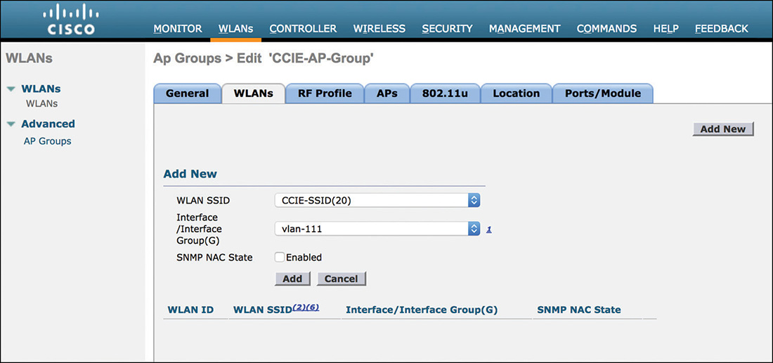
Previously, you could also remap a WLAN to a dynamic interface through an AP group to locally switch clients to the dynamic interface’s corresponding VLAN if the WLAN (and the APs serving it) were set for FlexConnect. In this case the dynamic interface’s VLAN didn’t necessarily have to exist centrally, behind the WLC, and the dynamic interface’s IP could even be a bogus one. This dynamic interface mapping had the main goal of communicating to the FlexConnect APs of the AP group the VLAN, on which to locally switch clients of that WLAN. Such a behavior originates by the fact that, without any other “overriding” options, a FlexConnect locally switched WLAN by default bridges clients on the same VLAN as the one from the dynamic interface assigned under the WLAN’s settings.
You can create multiple WLANs with the same SSID name, as long as they have different IDs (equal to or greater than 17) and profile names. Although today you can rely on standard IETF RADIUS attributes, such as the [32] NAS-Identifier or the [30] Called-Station-Id, to determine from which AP group or WLAN the client is connecting, in the past the only available option was the Cisco Vendor Specific Attribute (VSA) Airespace-Wlan-Id. By looking at the WLAN ID number from the Airespace-Wlan-Id attribute in RADIUS requests from the WLC, you could build authentication and authorization rules on your RADIUS server based on the client’s location. The client’s location in such a scenario would be the AP group, to which you could map a WLAN with the same SSID name as other WLANs but a different WLAN ID and profile name. Based on the location (or AP group) the client was connecting from, you might have wanted to dynamically assign different VLANs, ACLs, QoS parameters, and so on via RADIUS attributes. As of today things got a bit easier thanks to options to include the AP group name directly in the RADIUS attribute [30] Called-Station-Id, for example, but the technique we just described through WLAN IDs and AP groups was and still is a valid one to support such use cases.
Although the following may not be some very common examples, we still prefer to clarify the behavior of AP groups for some specific cases, because they could be less evident to troubleshoot if you find yourself in such scenarios:
If a client roams between APs assigned to different AP groups, where the same WLAN is mapped to different dynamic interfaces, the WLC keeps the client assigned to the same dynamic interface of the AP group from the initial association so not to disrupt the IP connectivity. This is similar to a Layer 3 roaming, although it is not a common scenario to have different physically adjacent AP groups, because APs covering adjacent areas, among which clients could roam, should usually be assigned to the same AP group.
If you need to support AP’s mobility between WLCs, we recommend always keeping the AP groups’ configuration the same. Not only should you configure AP groups with the same names and the same settings (for example, WLANs list, dynamic interfaces mapping, and so on), you should also keep the AP groups list identical on all WLCs by creating/deleting AP groups in the very same order. This should prevent any possible conflict when APs move from one WLC to another, to correctly inherit and preserve all AP groups’ configurations.
Not necessarily related to AP groups only, but having two WLANs with ID equal to or greater than 17, the same SSID name and tunneled to the same anchor WLC is not a supported scenario. You may want to deploy this combination to tunnel clients from the same SSID to different VLANs based on the AP group (for example, the location) they are connecting from. However, the piece of code determining to which WLAN the anchor WLC should tunnel clients is determining the WLAN on the SSID name base, and this could definitely cause conflicts when having multiple WLANs with the same SSID name. The enhancement CSCub68067 for improving such a behavior is currently open at the time of this book’s writing:
https://bst.cloudapps.cisco.com/bugsearch/bug/CSCub68067
As an alternative, you could achieve the same goal by using the same WLAN on different AP groups and relying on the RADIUS attribute [30] Called-Station-Id to include the AP group name in RADIUS requests from the WLC. If the WLAN is configured for 802.1X, for example, the RADIUS attribute [30] Called-Station-Id is automatically sent, and you can use it on the RADIUS server to decide which VLAN to dynamically assign.
Dynamic VLAN assignment is supported with an anchor WLC: the foreign WLC talking to the RADIUS server receives the VLAN through RADIUS attributes and communicates it to the anchor WLC via EoIP/CAPWAP so that the anchor WLC can assign the client to the dynamic interface corresponding to that VLAN.
If the WLAN is not configured for 802.1X, but just for simple PSK, for example, you could still enable MAC filtering to trigger RADIUS requests from the WLC and be able to assign VLANs based on the AP group value of the RADIUS attribute [30] Called-Station-Id. Even if this means that the WLC performs authentication for every client’s MAC from this moment on, on your RADIUS server you can configure rules to accept any MAC address. The additional goal here is to assign VLANs based on the AP group/location, because the WLAN was originally meant for PSK only and not to authenticate clients based on their MACs.
Figure 4-21 shows an example of such a technique, assuming a WLAN configured for WPA/WPA2 PSK with MAC filtering. The WLC is configured to send a column-separated concatenation of the AP’s MAC address, the WLAN’s name (for example, CCIE-SSID) and the AP group name (for example, CCIE-AP-Group) in the RADIUS attribute [30] Called-Station-Id. Cisco Identity Services Engine (ISE) has an authentication rule configured to match MAC authentication requests from the WLC for the WLAN CCIE-SSID, with the option to continue if a MAC address is not found in the internal endpoints database. This means that ISE basically accepts any MAC authentication from the WLC on that specific SSID. It does not matter whether the MAC address can be verified. The authorization rule is configured to check the AP group’s name, always included in the very same RADIUS attribute [30] Called-Station-Id, on which the authentication rule is based to match the WLAN’s name. Through these settings you could automatically assign endpoints connecting on your WPA/WPA2 PSK enabled WLAN to a specific VLAN, for example, simply based on the AP group where they are connecting from.
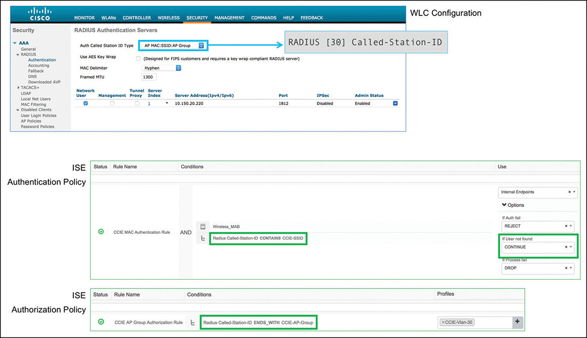
FlexConnect Groups
As the name already suggests, a FlexConnect group is mainly used to push FlexConnect parameters to a set of FlexConnect APs at once. FlexConnect groups do not modify any radio configuration, which is reserved to AP groups and RF profiles, if needed. The same AP can be a member of an AP group and a FlexConnect group; the two group categories are independent.
The FlexConnect group’s settings override the WLAN’s configuration, for example, for mapping a WLAN to a different VLAN from one of the dynamic interfaces assigned to the WLAN. By default, parameters under the FlexConnect tab of a single AP directly override the FlexConnect group’s configuration. For the native VLAN ID and WLAN-to-VLAN mappings of a FlexConnect AP, you can configure the FlexConnect group to take precedence by enabling the option Override VLAN on AP under the WLAN VLAN Mapping tab of the FlexConnect group itself.
Other settings that you can dynamically push via RADIUS attributes (for example, VLANs, ACLs, and so on) have the highest priority and override the configuration at the single AP’s level too.
Note
Usually, all settings applied through a FlexConnect group are available in each AP’s specific configuration, under the FlexConnect tab. The main exceptions are FlexConnect AVC Profiles and FlexConnect VLAN Templates. To deploy these features you must assign FlexConnect APs to a FlexConnect group, under which you select the AVC profiles and VLAN templates to push to those APs.
Along with pushing FlexConnect options to multiple APs concurrently, a FlexConnect group plays a fundamental role for keys reuse in roaming scenarios. FlexConnect APs with local switching support the following main roaming techniques: Cisco Centralized Key Management (CCKM), Opportunistic Key Caching (OKC), and Fast BSS Transition with 802.11r. For key caches to be shared and for such roaming options to be supported within a set of FlexConnect APs, those FlexConnect APs must be in the same FlexConnect group. Even if at the very beginning of a multisite FlexConnect deployment you may not need to group APs, support a specific roaming technique, or push multiple common settings in parallel, we still recommend to group APs from the start, both through AP and FlexConnect groups. You might have to spend some extra time planning those groups, but such an initial effort could be much smaller than the one required during the production phase, for example, in case new needs are raised at a later stage.
Wireless Security Policies
Security is a pervasive topic, specifically on wireless networks, where we sometimes take it even more for granted than on wired networks. Because wireless is not something we can actually “see,” like Ethernet cables, and because we cannot always fully control the range of a Wi-Fi signal, there is often a bigger focus on how to secure something for which we already have less physical visibility. Through the next sections we will try to address all security options from different perspectives: the WLAN, the client, the radio infrastructure, and so on.
To Layer 2 or To Layer 3?
When creating a WLAN, one of the first decisions you probably need to make is whether that SSID will be an open or a secure one. We can define an open SSID as having no encryption. Although still supported, because WEP is nowadays not recommended whatsoever, we could simplify this reasoning a step further and think of “open vs. secure” as “open vs. WPA/WPA2 encrypted.” This first distinction determines the level of Layer 2 security of your SSID; it does not, however, define the authentication method yet.
A very important point we should clarify from the beginning is that a secure SSID cannot fall back to open. For instance, if an SSID is configured for WPA/WPA2 with 802.1X authentication, a client cannot connect anyway through MAC authentication in case it doesn’t support any EAP method. For 802.1X on wired networks you may sometimes have options on the switch allowing authenticating clients through MAC authentication bypass (MAB) if they don’t support 802.1X. This is possible because on wired networks we don’t encrypt the wired communication between the client and the switch. (Well, historically we didn’t, at least not before the introduction of IEEE 802.1AE with MACsec.) On wireless networks, if we configure a secure WLAN with WPA/WPA2, the client must support encryption too. More precisely, it must install a Pairwise Master Key (PMK) from which to derive other encryption keys. The PMK is installed in two ways, either statically because it is derived from a passphrase (that is, a pre-shared key, or PSK), or dynamically because it is assigned by a RADIUS server at the end of an EAP authentication. Without a PMK to derive encryption keys from, a client cannot complete the association to a WPA/WPA2 secured SSID. On a WPA/WPA2 secured SSID configured for 802.1X, if the client didn’t support 802.1X, it could not obtain the PMK at the end of the EAP authentication process and derive the encryption keys to connect. On wireless networks, there is no option to fall back to open.
Another fundamental concept to keep in mind is that when you configure a secure SSID for WPA/WPA2, you can choose either a PSK-based or an 802.1X-based Authentication Key Management mechanism, but not both under the same WLAN. This means that you can support either statically assigned keys (through a passphrase, PSK) or dynamically assigned keys (through 802.1X), but both cannot coexist on the same SSID.
Open and secure are the two options for the Layer 2 security level. On top of these, we should be aware of the differences between Layer 2 and Layer 3 authentication techniques. Although it may sound self-explanatory, we could think of Layer 2 authentication as the authentication process at the end of which a client gains access to the network’s Layer 2. This could translate in the client’s traffic being authorized on a specific VLAN, for example. A Layer 3 authentication, on the other hand, takes place when the client already has access to Layer 2 and allows authorizing further access to Layer 3 services or above (for example, communication with a VPN gateway or HTTP(S) access to certain web pages). A Layer 3 authentication is usually performed after a client already obtained an IP address.
If we had to translate Layer 2 versus Layer 3 authentication techniques to a WLAN’s configuration, we could say that Layer 2 authentication options are those related to MAC filtering or 802.1X, and that Layer 3 authentication options are all those related to web authentication. MAC filtering and/or 802.1X are performed before authorizing the client’s traffic through the AP; hence they are part of the Layer 2 authentication process.
Again, for the sake of simplicity and because WEP is not recommended anymore, we will use 802.1X to refer to a WLAN configured for WPA+WPA2 as Layer 2 Security, and with 802.1X, CCKM or FT 802.1X under the Authentication Key Management parameters. 802.1X, CCKM, and FT 802.1X refer more to the key management options for roaming, correspondingly with OKC, CCKM, and 802.11r. All these options are based on 802.1X authentication and can all coexist for the same WLAN. Figure 4-22 shows an example of Layer 2 security options for a WLAN.
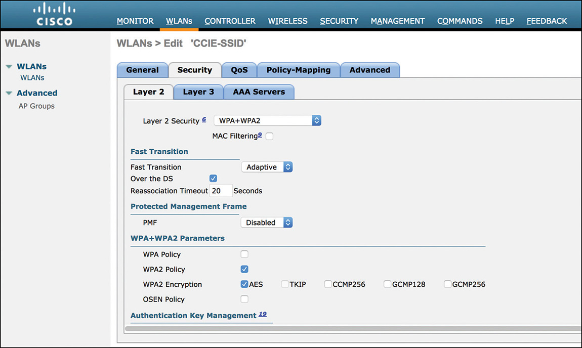
802.1X automatically implies that the SSID is secure. Although MAC filtering is a Layer 2 authentication technique, it applies to both open and secure SSIDs. When applied to a PSK secured SSID, for example, the WLC tries to authenticate MAC addresses, either against the internal MAC filtering list under SECURITY > AAA > MAC Filtering or against an external RADIUS server. On top of that, the client must go through the encryption keys derivation process, too, before traffic can start being forwarded.
Applying MAC filtering on top of an 802.1X secured SSID is technically possible and supported, but it does not make too much sense in the majority of scenarios. First, because of its very nature, MAC filtering would not add any security advantage on top of 802.1X. Also, the WLC sends the client’s MAC address in the RADIUS attribute [31] Calling-Station-Id when performing 802.1X authentications. By adding checks in your RADIUS server’s rules for the Calling-Station-Id attribute sent during 802.1X authentications, you can perform MAC authentications in parallel too. If, on top of an 802.1X-based Authentication Key Management option under the WLAN’s Layer 2 security tab, you also checked the option for MAC Filtering, the WLC would perform an additional, distinct MAC authentication. Although negligible sometimes, this could still introduce some extra delay in the client’s overall association workflow.
When configuring an open SSID, you can either apply MAC filtering as the only authentication technique or deploy it on top of Layer 3 authentication. The Layer 3 authentication options that you can configure under a WLAN are all translating into web authentication techniques with the Local Web Authentication (LWA) method (more on this in Chapter 5, “Wireless Security and Identity Management with ISE”). To enable Layer 3 authentication you need to change Layer 3 Security from None to Web Policy under the WLAN’s Layer 3 subtab of the main Security tab. Enabling the Web Policy option automatically enables the WLC to allow DNS traffic for clients associated to the WLAN, even when they are still redirected to the web portal (that is, in the WEBAUTH_REQD state).
Note
Although the WLC automatically permits certain categories of traffic for web authentication, you may still want to explicitly permit DHCP and DNS at the beginning of a pre-web authentication ACL. In this way you will have access to specific counters of the ACL, also for permitted DHCP and DNS traffic. Such a technique could provide some more visibility in case of troubleshooting and let you confirm whether clients can successfully obtain IP addresses via DHCP and perform DNS resolutions, for example.
MAC filtering and web authentication can both coexist on the same WLAN, or you can configure web authentication as a fallback mechanism if MAC filtering fails. A use case for this option could be to authenticate specific devices against a MAC addresses database and, still on the same SSID, to provide guest access too.
For a secure SSID, you can also combine Layer 2 and Layer 3 authentication methods. In such a case, you cannot use web authentication as a fallback mechanism: a device must first pass the Layer 2 security and authentication phase, if configured, before going through web authentication. We explicitly used the words “if configured” for Layer 2 authentication because you could, for example, have a WLAN with WPA/WPA2 PSK before web authentication, in which case there would be no Layer 2 authentication. Clients connecting to such a WLAN still need to go through the WPA/WPA2 six/four-way handshake before they can get redirected to a web portal. If you decide to configure a secure SSID and chain 802.1X with web authentication, which is a supported combination, too, clients need to successfully authenticate via 802.1X before being able to go through a web portal. Chaining 802.1X and web authentication with LWA is supported only if the web authentication option is for a portal asking for login and password. A passthrough portal, for example, is not supported if LWA is chained with 802.1X. This combination of 802.1X plus LWA was introduced to support some sort of machine and user authentication for those devices, usually non-Windows-based ones, which are not supporting distinct machine and user identities. You could, for example, authenticate a tablet through 802.1X with a certificate issued for the machine name, and then users behind that tablet through a web portal and their Active Directory credentials.
Some organizations, however, may decide to use 802.1X to authenticate guest users, while still redirecting to a web portal after that authentication, to display terms and conditions through an acceptable use policy (AUP) page. Some of the main reasons for using 802.1X authentication for guest users are the following:
It is more secure than an open SSID, with encrypted traffic.
Users without any credentials cannot even associate to the WLAN to get redirected to a web portal. In this way, they cannot consume network resources, such as IP addresses, either.
Devices tend to cache 802.1X credentials, for example for PEAP MS-CHAPv2, so end users might not need to enter them multiple times.
As mentioned earlier, 802.1X chained with LWA supports only a web login page as a guest portal. To chain 802.1X with a web passthrough portal, you can instead use Central Web Authentication (CWA) with Identity Services Engine (ISE). 802.1X plus CWA allows you to redirect guest users to a passthrough web portal (that is, a “hotspot” portal in the ISE’s jargon) after 802.1X authentication.
WLAN Security Options
To configure L2 and L3 security and authentication options of an SSID, you can browse under the corresponding Security tab of your WLAN. As the menus present themselves, the Layer 2 subtab lists all the Layer 2 security and authentication features, and the Layer 3 subtab contains the options to implement LWA.
Layer 2 security options allow choosing between an open and a secure SSID. For a secure SSID, probably the most used encryption method is WPA+WPA2. As of today, the Wi-Fi Alliance is deprecating the use of WEP, and also of WPA TKIP as the only cipher option for a WLAN. If you need support for WPA TKIP on an SSID, you need to enable WPA2 AES too, for example.
AireOS 8.3 introduced the support for some security and QoS features co-developed with Apple, and more specifically for Adaptive 802.11r. Roaming and key management techniques, such as 802.11r, are explained later in this chapter.
When you enable Adaptive 802.11r, sometime also referred to as Adaptive Fast Transition (FT), APs will include an optional CCX Information Element (IE) in their beacons with a specific bit set to indicate support for 802.11r. This CCX IE is understood by Apple devices only, which can then negotiate support for 802.11r in the association phase. Other non-Apple devices not understanding such a CCX IE will not detect that the WLAN supports 802.11r, and they will complete the association process without negotiating 802.11r. When choosing WPA+WPA2 as the Layer 2 security option for your SSID and enabling at least a WPA2 cipher suite, Adaptive 802.11r is also automatically enabled by default.
On top of cipher suite and Fast Transition options, in the same Layer 2 security subtab you can find settings to enable different authentication key management methods for roaming, which are also covered later, along with some documentation.
Through the Layer 3 security subtab you can configure Local Web Authentication (LWA) scenarios. By selecting Web Policy in the Layer 3 Security drop-down menu, you have the option of selecting among several web portal redirection flavors. You can find all the details on these different techniques, and how to configure them, in the following official guide:
On top of the main options we just discussed, you can enable additional security features on a WLAN that can be applied to both Layer 2 and Layer 3 authentication methods. You can find these additional options under the Advanced tab of a WLAN’s configuration in the controller’s GUI. The following list describes some often used ones:
AAA Override: When you enable this option you are basically telling the WLC to accept RADIUS attributes to dynamically assign L2/L3 policies that might override those statically configured under the WLAN. The most common example is dynamic VLAN assignment. With AAA override enabled, if the RADIUS server passes back the needed attributes to the WLC for assigning a VLAN, the client is switched to the dynamic interface corresponding to that VLAN instead of the interface “statically” configured on the WLAN (under the WLAN’s General tab). Other examples of dynamically overridden options through RADIUS attributes are ACLs, the session timeout, QoS profiles, AVC profiles, and so on.
Peer to Peer (P2P) Blocking: This feature allows you to block traffic between clients connected to the same WLAN. When you configure the P2P blocking action to Drop, traffic between clients of the same WLAN is blocked at the WLC level. With the Forward-UpStream action, the WLC does not directly bridge traffic between two clients, but it forwards it to the upstream network device for it to apply any potential blocking action.
For centrally switched clients, P2P blocking applies to clients of the same WLAN and same VLAN, even if they are connected to different APs. For locally switched clients, P2P blocking applies to clients of the same WLAN, the same VLAN, and connected to the same FlexConnect AP. COS APs support P2P blocking for locally switched clients starting only from AireOS 8.7. You may want to keep P2P blocking disabled for enterprise or voice networks and enable it for guest networks, for example.
Client Exclusion: With this feature enabled by default with a timeout of 60 seconds, clients failing 802.11 association or 802.11 authentication five consecutive times, or also 802.1X authentication or web authentication three consecutive times, are put in an exclusion list for 60 seconds. During this time they will be denied access to the WLAN based on MAC address “blacklist.” A client using an IP address already assigned to another device is also excluded, if Client Exclusion is enabled. You can customize which client exclusion policies to keep enabled through the WLC’s GUI, under SECURITY > Wireless Protection Policies > Client Exclusion Policies.
Because it may help to prevent brute force attacks, for example, it is generally a common practice to keep client exclusion policies enabled; in some specific scenarios or for testing purposes, however, you might need to disable them.
DHCP Address Assignment: Through this function you can block clients from getting to the RUN state if they do not complete IP assignment via DHCP. Clients with static IPs (printers or similar) cannot transition to the RUN state when DHCP Address Assignment is set to Required. This is a setting that you might often see recommended for guest networks, or more generally for WLANs not having specific needs for static IPs support.
Under the WLAN’s options you can definitely find more settings than those just listed, although the ones mentioned here are probably considered some of the most common ones. Additional details on all other parameters can be found in the official configuration guide:
Rogue Policies
On top of specific options in the WLAN’s configuration, you can add further security measures to your wireless network by deploying policies to detect and mitigate rogue access points. The very definition of a rogue AP is an access point not known by any WLC in the same RF group or mobility group. APs from your deployment forward information about other detected APs to the WLC, and the WLC checks whether those newly detected APs are known through another WLC in the same mobility group, or else because their RF neighbor messages heard by your APs included the same RF group name. If none of these checks succeeds, the newly detected AP is flagged as a rogue, and rogue policies configured on the WLC may apply. Some official guides mention three distinct phases for rogue AP operations: detection, classification, and mitigation. The detection phase consists of the steps just mentioned: an AP of your deployment and its WLC flagging an external AP as unknown, or rogue. Classification and mitigation are the results of rogue rules that you configure on the WLC.
You can find rogue policies and rules under the WLC’s menu SECURITY > Wireless Protection Policies > Rogue Policies. Among the general settings are three pre-canned configuration models corresponding to the level of “aggressiveness” with which the WLC detects rogue APs, keeps them in the corresponding list as such, attempts to determine whether they are connected to your LAN, and so on.
A common practice is to set the Rogue Detection Security Level to Low as a starting point. This level is generally used for plain detection: the Rogue Detection Minimum RSSI at −80 dBm, for example, is often enough to filter out rogue APs that could be too far away. If needed, you can always switch to the Custom mode, to modify some parameters after having started from one of the other three templates.
General settings for rogue policies define the main criteria, based on which the WLC performs detection, as well as some other mitigation actions. For more specific rogue APs classification, you can add rules and conditions under the dedicated Rogue Rules menu.
Results of a rogue rule are a classification and an action. Classifications can vary among Friendly, Malicious, or Custom, and an action (or State, in the WLC’s GUI) can be a containment, an alert, a further classification as internal/external (in case of Friendly classification), or else the deletion of the rogue AP’s MAC from the WLC’s tables. It’s quite common to configure rogue rules for alerting, which the WLC triggers through messages directly on its interface and through SNMP traps, for integration with external monitoring tools. The containment action is performed by one or more of your infrastructure’s APs by sending deauthentication frames to clients associated to the rogue AP, hence “containing” it from connecting users or devices. You may not always want to configure such an action, however; while busy containing rogue APs, infrastructure APs are not able to serve clients as usual, so your wireless network’s overall performance is slightly impacted. Also, containing another wireless network might be considered illegal in some countries. A more commonly adopted approach is to configure rogue rules for alerting actions only, while completing such functions with rogue AP location tracking through Prime Infrastructure and MSE, to then physically check a specific location for rogue APs and try to understand why they might be present and how to act (or not) on them. Although less automated and more dependent on physically checking the zone of impact of a rogue AP, this combination is a bit more careful in not disrupting other wireless networks without a final human confirmation.
Note
Rogue location on CMX is supported starting from version 10.4. Although by the time of this book’s writing you can integrate rogue location with Prime Infrastructure and CMX, for the purpose of the CCIE Wireless exam based on CMX 10.3, rogue location would still need the former MSE solution.
Conditions from a rogue rule can be based on different information seen from the rogue AP, such as the SSID name (or a substring of it), the maximum RSSI, whether the rogue AP is serving an SSID with the same name as one of the SSIDs managed by your WLC, and so on. A very common example of classifying rogue APs as malicious, just for alerting purposes to start with, can be a rule matching the condition for a Managed SSID, as shown in Figure 4-23.
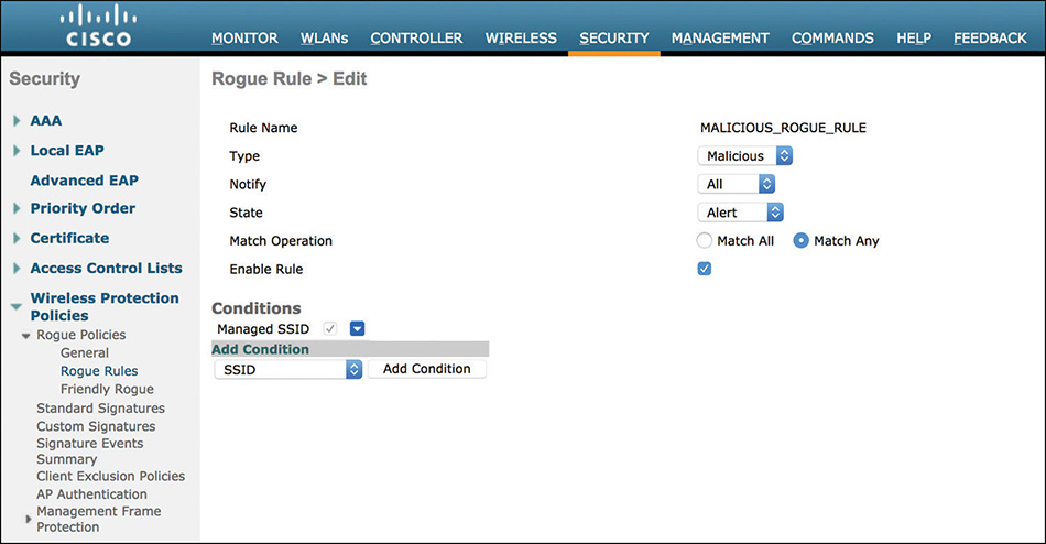
On top of the WLC’s rules to classify rogue APs, you can also implement additional options to try to determine whether a detected rogue AP is connected to your wired network infrastructure:
Rogue Location Discovery Protocol (RLDP): When this feature is enabled, an infrastructure AP having detected a rogue AP tries to associate to that rogue AP as a standard client. If it succeeds and obtains an IP address, it then tries to send a specific discovery message to the WLC’s management interface on the UDP port 6352. If such a message reaches the WLC, the rogue is additionally classified as “on wired,” meaning connected to your LAN. RLDP has of course some limitations, such as being supported only if the rogue AP’s SSID is open and not secured. Additionally, while trying to associate to the rogue AP, the RLDP enabled infrastructure AP may stop serving clients for up to 30 seconds. Finally, if the rogue AP is configured with options to filter out those UDP messages to the WLC (or if there is no routing from there to the WLC), RLDP might fail. You should also be aware that RLDP is nowadays deprecated on COS APs (for example, 1800/2800/3800 series and any other 802.11ac Wave 2 AP model).
Rogue Detector mode: This is a specific operational mode that you can configure on one or more infrastructure APs, similarly as for Local or FlexConnect modes. When you configure an AP in Rogue Detector mode, radios are disabled and on its Ethernet port the AP listens for ARP messages from the rogue AP’s MAC itself or a rogue client’s MAC (these MAC addresses being known, thanks to other infrastructure APs having detected them). On the wired side, the Rogue Detector AP should be connected to a dedicated switchport, usually in trunk mode, where you allow all necessary VLANs to be monitored. If an AP in Rogue Detector mode receives an ARP message from a rogue AP’s MAC or one of its rogue clients’ MAC detected over the wireless by other infrastructure APs, the specific rogue AP might be connected to your LAN on one of the monitored VLANs. Rogue Detector APs support detection of up to 500 rogue MACs and may not correctly detect a rogue on wired if that rogue AP applies network address translation (NAT) or similar for MACs. As for the previous option, Rogue Detector mode is deprecated for COS APs.
Switch Port Tracing (SPT): Although not a WLC feature, this option allows you to detect rogue APs connected to one of your switches through Prime Infrastructure. Because it is more specific to the management solution, we detailed SPT in Chapter 6, “Prime Infrastructure and MSE/CMX.”
CleanAir: Even if CleanAir is usually presented as the Cisco solution for interferences detection, in some corner cases it could be beneficial for “rogues” too. We explicitly used the word “rogues” between quotes here because, although technically speaking these are still interferences and not rogues, devices acting as Invalid Channel or Inverted Wi-Fi may still connect older legacy clients that would “see” them as standard Wi-Fi APs. By using these interferences as some sort of APs, a malicious user might be able to set up his/her own rogue network in kind of a “stealth” mode, because APs not supporting interference detection wouldn’t be able to catch it. Again, it’s a very specific and less likely corner case, but to push the exercise a bit further, we could think of CleanAir as an additional “rogue” detection feature.
For the sake of not duplicating resources, we leave additional details on rogue management to its dedicated white paper on Cisco.com:
https://www.cisco.com/c/en/us/td/docs/wireless/technology/roguedetection_deploy/Rogue_Detection.html
Local EAP, Local Profiling, and Local Policies
In the vast majority of production deployments, you might encounter a dedicated AAA/RADIUS server solution for authenticating users and devices, classifying them, and applying specific policies. Generally speaking this is also the recommended approach, because a full-blown AAA/RADIUS server supports all the needed features to integrate with external databases, private key infrastructures (PKI), monitor authentications, and the like. However, for some situations, where an external AAA/RADIUS server may not be available, the WLC offers some local options to authenticate users or devices, classify those devices, and enforce policies.
For 802.1X authentications, the WLC supports login-based EAP methods, such as LEAP, EAP-FAST, and PEAP, with user accounts from its local database. Local EAP settings are available under SECURITY > Local EAP > Profiles.
You can create and manage the list of user accounts under SECURITY > AAA > Local Net Users.
On top of login-based EAP methods, the WLC supports EAP-TLS as a certificate-based authentication technique. Login, or more precisely tunnel-based, authentication methods and EAP-TLS require a server certificate and, for EAP-TLS, a root certification authority certificate to trust the clients’ certificates. Both the WLC’s server certificate and the root CA certificate can be uploaded under COMMANDS > Download File, respectively with the options for Vendor Device Certificate and Vendor CA Certificate under the File Type drop-down menu. To generate a WLC’s server certificate for EAP-TLS, you can follow the same procedure as for the web authentication certificate, although the CN should differ from the IP or the FQDN of the virtual interface in this case:
The workflow to enable local EAP for an SSID consists in first creating a local EAP profile with the supported EAP methods, and then in linking that profile to the WLAN, under its Security > AAA Servers tab. Before starting using it, you should also make sure that the needed user accounts are created or that the right WLC’s certificates have been uploaded.
You can find additional configuration details on local EAP in its dedicated section of the configuration guide:
On top of local authentication features, you can also enable devices’ classification options on the WLC, either to reuse those classifications for local policies or just for monitoring purposes. Devices classification on the WLC is derived from Cisco Identity Services Engine (ISE), and we refer to this function as local profiling.
When you enable local profiling for a WLAN, under Advanced > Local Client Profiling, APs serving that WLAN communicate to the WLC the following information that they can monitor from the clients’ traffic: the MAC address, the DHCP attributes for hostname and class identifier (if DHCP Profiling is checked), and the HTTP user agent (if HTTP Profiling is checked). With these data and their values, the WLC can match a specific client (that is, its MAC address) to one of the pre-canned profiles among those in the list visible through the command show profiling policy summary.
The rules to match a client to a profile are the same as you could find in the profiling policies in Cisco ISE. Although the WLC does not support modifying its local profiling policies, it supports importing new versions of them. Under COMMANDS > Download File and through the Device Profile file type, you can import new versions of profiling rules, which you could have previously exported from ISE, for example. To update the OUI database, you can follow the same procedure by using the file type OUI Update instead.
As a further extension of local AAA features on the WLC, you can also use 802.1X/EAP methods and device profiles as conditions to match and apply local policies to users or devices of a specific SSID.
You can create and modify local policies on the WLC under SECURITY > Local Policies, as shown in Figure 4-24. A local policy is matched based on the role string, the EAP method (both through local EAP or when authenticating through an external RADIUS server), or the device type from the local profiling. When a client matches a local policy, different types of settings can be assigned to it. The most common ones are a VLAN, an ACL, and a QoS profile, but you can also implement more advanced options, such as an AVC profile or an mDNS service.
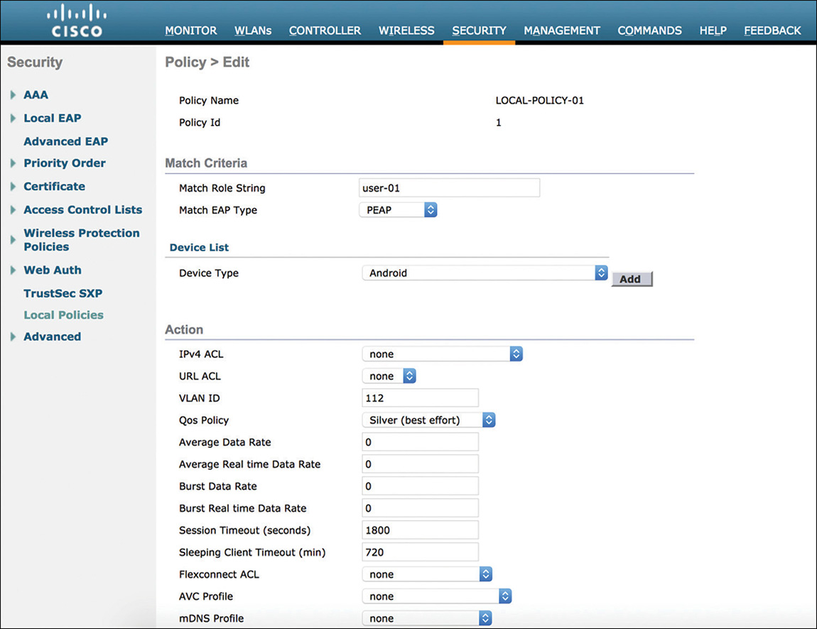
You can link multiple local policies to a WLAN, under its Policy-Mapping tab, where they will be processed according to the order assigned in that list. As a further option, you can dynamically assign a local policy to a user or a device via RADIUS attributes. When authenticating a client through an external RADIUS server, the WLC supports dynamic assignment of local policies through the role string, communicated to the WLC in the vendor specific attribute (VSA) cisco-av-pair=role=<role_string>. All the settings that you can assign within a local policy (VLAN, ACL, QoS profile, AVC profile, and so on) can be assigned one by one through corresponding RADIUS attributes. The purpose of assigning them all together through a local policy’s name would be the simplicity of configuring and sending just one RADIUS attribute in the final access-accept. However, for monitoring and tracking purposes, you may still want to dynamically assign settings one by one, through multiple RADIUS attributes in the final access-accept.
The full configuration guide for local profiling and policies is available here:
ACLs and Certificates
Access control lists and certificates are some more “classic” security options, which you can find extensively detailed in the configuration guides. We will briefly go through some of their uses, while leaving all the other already available information to the online guides.
ACLs on a WLC are historically Layer 3 or Layer 4 ACLs and you can configure them under SECURITY > Access Control Lists. An ACL allows filtering based on IPs or subnets, both as source and destination, but also based on protocols, ports, and DSCP values. You can also specify in which direction an ACL should apply; inbound or outbound. Inbound means traffic coming in from the wireless clients, and outbound means traffic going out to the wireless clients.
You can statically apply ACLs to a dynamic interface or to a WLAN, or you can dynamically assign them through the RADIUS vendor-specific attribute Airespace-ACL-Name. ACLs also serve as pre-web authentication ACLs, again either statically configured under a WLAN for Local Web Authentication (LWA) or dynamically assigned via the RADIUS attribute cisco-av-pair=url-redirect-acl=<ACL_NAME> for Central Web Authentication (CWA).
Under an ACL you can configure permit statements for fully qualified domain names (FQDN) too, as shown in Figure 4-25. These statements apply to clients in the WEBAUTH_REQD state, or any other state for web redirection, hence only if the ACL is used as a pre-web authentication ACL.
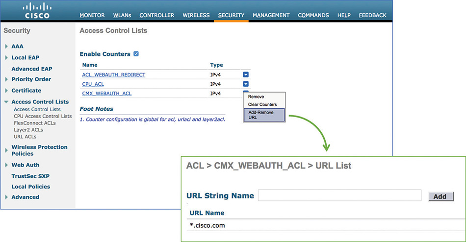
As of AireOS 8.4 you also have the option to configure FQDN ACLs for clients in the RUN state. These can be found under SECURITY > Access Control Lists > URL ACLs, and in the corresponding configuration guide they are sometimes referred to as URL ACLs:
A more accurate technical definition would be FQDN ACLs. They do not allow you to configure full URLs and sub-URLs, for example, but just FQDNs. For example, “acme.com” is a supported entry, but “acme.com/licensing” is not.
As an additional option for ACLs, the WLC supports L2 ACLs too:
On the WLC there are different types of certificates for different uses, all of which you can download to the WLC under COMMANDS > Download File. We can distinguish three main certificates:
Web management: This is the certificate used for the web graphical user interface of the WLC, when accessed via HTTPS, and you can download it to the WLC by selecting the file type WebAdmin Certificate. Although used for a different purpose, you can generate such a certificate in the very same way as for the web authentication portal’s certificate, by generating a certificate signing request (CSR) and then requesting and installing the certificate on the WLC:
In case of the web admin certificate, you should specify the management IP of the WLC or its FQDN in the certificate’s common name, and not the virtual interface’s IP or FQDN as for the web authentication portal’s certificate. As an additional method, you can generate the CSR for this certificate through the command config certificate generate csr-webadmin and its options.
Web authentication portal: This is the certificate presented when being redirected to the web portal hosted on the virtual interface, and its common name should be the virtual interface’s IP or FQDN. In the same way as for the web admin certificate, you can generate the CSR for the web authentication certificate through OpenSSL, or even through the WLC’s command config certificate generate csr-webauth and its options. All the configuration details are the same as in the aforementioned URL.
EAP certificate: This is the authentication server certificate for the WLC when using local EAP profiles. Under the GUI, you can download such a certificate under COMMANDS > Download File by choosing Vendor Device Certificate as a file type; this corresponds to the data type option eapdevcert when using the transfer download command line. Although usually recommended for ease of use, the common name for the EAP device certificate does not necessarily need to match the WLC’s management IP or FQDN, because during an EAP authentication a client does not/cannot reach that IP/FQDN to verify it. Along with the EAP certificate for the WLC itself, you also must download the certification authority’s certificate to trust clients’ certificates for EAP-TLS, for example. You can follow the same procedure as for the device certificate, by choosing Vendor CA Certificate as a file type in the GUI, or eapcacert as a data type via CLI.
On top of these main use cases, the WLC also supports the download of other types of certificates, such as the CA server certificate for LSC certificates installation on APs, which we discussed in the previous sections.
FlexConnect Deployments
FlexConnect is a special mode in which you can set mostly any access points (there have been some restrictions on the AP model in the past, but all AP models from the exam support it). We have mentioned it many times already in this book, but let’s cover its specifics.
What Problem Are We Trying to Solve?
The FlexConnect mode doesn’t do or change anything per se (that is, if it’s the only thing you enable) apart from adapting the AP state machine, behaviors, and timers to act properly considering there is a WAN link between it and the WLC. Moving an AP to FlexConnect mode does not require a reboot and is close to instantaneous, but moving an AP back to local mode requires a reboot.
The requirements for FlexConnect mode are the following: less than 100ms latency between AP and WLC (if only doing data, up to 300ms can be tolerated), 128kbps of bandwidth per group of 8 APs, and at least an MTU of 500. The AP itself is very delay tolerant, but the client does not necessarily realize that the AP needs to consult with a WLC behind a WAN link, and issues may arise if latency is longer than 100ms because of the client growing impatient. There are CAPWAP heartbeats every 30 seconds and if one is lost, five (one per second) are sent consecutively. If they fail, the connectivity is declared lost, and the AP moves to standalone mode; therefore, there is some small tolerance to packet drop but it shouldn’t be abused.
FlexConnect Modes and States
There are two traffic switching modes in FlexConnect: central and local switching. With a default WLAN configuration, FlexConnect mode APs will centrally switch client traffic, which means that they will send all the client traffic in a CAPWAP tunnel to the WLC. There is no change of behavior (from a traffic switching perspective) compared to a non-FlexConnect AP (that is, local mode). However, if the WLAN has the check box for FlexConnect Local Switching, this WLAN will be locally switched on all the APs that are in FlexConnect mode (local mode APs will still behave as they always do). This means that the AP gives the client traffic directly to the connected switch without any encapsulation. The AP still has a CAPWAP tunnel for control traffic: AP configuration, WLC statistics and monitoring, but also client authentication. But as soon as the client is in RUN state (fully forwarding the client traffic), the AP converts the 802.11 frame to an 802.3 frame and sends it on its connected switch (much like autonomous IOS APs did). APs can support several VLAN tags in such a mode and have some WLANs centrally switched while others will be locally switched on the connected switch at the branch. Figure 4-26 illustrates the WLAN settings that will allow you to configure some WLANs as locally switched while others will stay centrally switched:
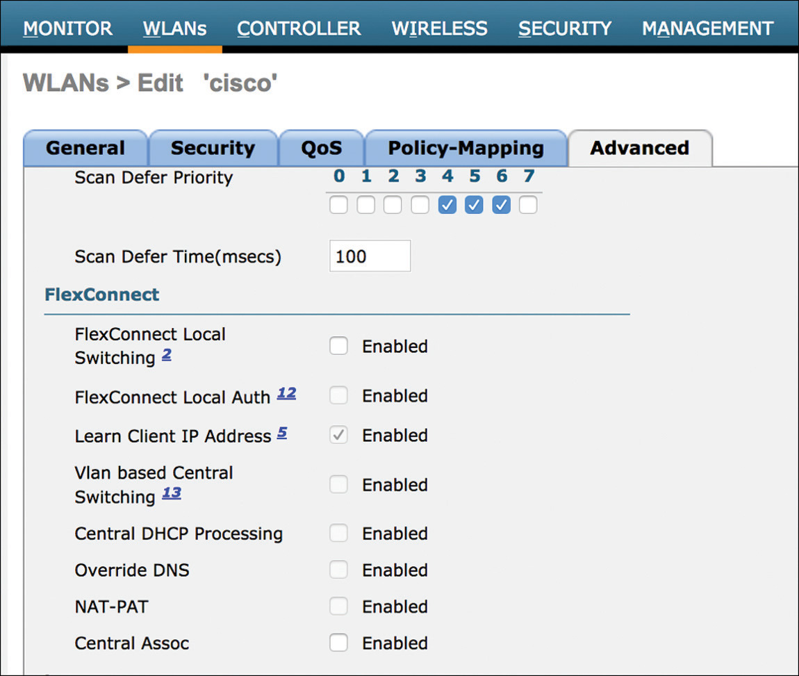
There is a small catch to the previous paragraph though. We already hinted that the client authentication will still be sent in the CAPWAP tunnel as control traffic to the WLC (although there’s a feature to have this taken care of by the AP, but one thing at a time), so you might be tempted to say that all traffic before the RUN client state is sent to the WLC, and locally switched at the remote branched afterwards, but this is wrong because of DHCP. Because the client traffic will be switched at the branch, we expect the client to have a gateway defined at the remote branch office (for efficiency reasons) and therefore, the client should obtain its IP address from the remote branch as well. This means that DHCP traffic from the client will also be switched at the remote branch. A good summarization is to say that locally switched WLANs do not require a dynamic interface configuration on the WLC (and will not care which interface you configured on the WLAN settings) but only require you to specify a VLAN ID in which they will be switched at the remote office, while centrally switched WLANs do not care about the remote office VLAN configurations because everything is tunneled to the WLC in the AP native VLAN (and therefore WLC dynamic interfaces are critical to switch client traffic).
The FlexConnect AP can be in any of the following two situations (they are called modes, but they are more like situations than modes you can enable):
Connected: This means that the AP has full connectivity to the WLC. It is in full working condition and works as you probably expect it to.
Standalone: The connectivity got lost to the WLC and the AP, while actively trying to find the WLC again, will still try to service some WLANs under some conditions. This is definitely a situation that you do not choose, that you suffer from, and that everyone should remediate as quickly as possible (by regaining WLC connectivity).
FlexConnect APs can end up in any of the following states for each WLAN they service:
Authentication central/switching central: This is the state of a FlexConnect AP when it is connected to the WLC and when the WLAN is not configured for local switching. All traffic is forwarded to the WLC, and the WLAN works only when the AP is connected to the WLC.
Authentication down/switching down: This is the state the AP will end up in when it loses the WLC connectivity in the previous example (FlexConnect central switching SSID). All current clients are deauthenticated by the AP and it stops beaconing. The only way out of this state is to regain connectivity to the WLC.
Authentication central/switching local: This is the state of the AP when you enable FlexConnect Local Switching on the WLAN configuration page. All traffic (except authentication) is switched locally at the remote branch. This works only when the AP is connected to the WLC. This state is illustrated in Figure 4-27.
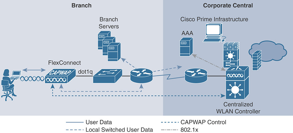
Figure 4-27 Authentication Central/Switching Local Authentication down/switching local: If connectivity is lost from the previous example (authentication central/switching local), we cannot authenticate or accept new clients on the SSID because WLC is not available. Client traffic keeps being forwarded until the session timeout, and the WLAN stays up until the last client leaves (then the WLAN will be down because it can’t accept new clients). This state is found only in standalone mode, as illustrated in Figure 4-28.
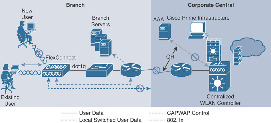
Figure 4-28 Authentication Down/Switching Local Authentication local/switching local: If you manually configure local authentication on top of local switching, the AP is as resilient as it can be for this WLAN. Even if WLC connectivity is lost, the AP will continue to function and fully operate on this WLAN. There are, however, some limitations with regard to authentication types that the AP can handle (mainly regarding EAP authentications, while some other methods, like Open authentication or WPA/WPA2-PSK, can be handled at the AP for new clients without any local authentication configuration but when the AP is in standalone mode after losing connection with the WLC).
It is important to note that FlexConnect brings some limitations to certain features: sometimes only in local switching mode, sometimes across the board. Take a look at the “FlexConnect Feature Matrix” online for a list of what is supported in what mode.
FlexConnect Specific Features
The WLAN Advanced tab contains a few more FlexConnect specific features:
FlexConnect local switching: When enabled, this WLAN will be locally switched on all FlexConnect APs.
FlexConnect local auth: This enables FlexConnect APs to take care of the authentication as well locally. They will fallback to local authentication in standalone mode. Note that you will have to enable local auth as well in the FlexConnect group options to have the AP always using local authentication (even in connected mode).
Learn Client IP address: Because the DHCP traffic is switched at the remote office, the WLC doesn’t have the opportunity to track the client IP address. If you enable this feature, the AP will send a copy of the DHCP packets inside the CAPWAP tunnel for the WLC to learn the client IP address.
VLAN-based central switching: When enabled, this feature allows having some clients centrally switched and other clients locally switched on the same WLAN on the same FlexConnect AP. With this feature disabled, you can assign a dynamic VLAN in the AAA attributes after the client authentication, and if the VLAN exists on the AP, the client will be switched locally on that VLAN. However, if the VLAN does not exist on the AP, the client is unable to connect. With this feature enabled, if the AAA server returns a VLAN that does not exist on the AP, the client will be centrally switched on the WLC with the interface that corresponds to that VLAN (if it exists; if that VLAN is also not present on the WLC, then the WLAN default interface is chosen).
Central DHCP Processing: In some cases, you might want FlexConnect locally switched clients to still obtain their IP from a central DHCP. A great configuration example is available online if you search for “FlexConnect Central DHCP configuration example.”
NAT-PAT: If you enable Central DHCP Processing, but the subnet used by the dynamic interface on the WLC does not exist on the remote office site, you must enable NAT-PAT for the AP to do NAT on the client traffic so that the client can talk to the remote resources.
Central Assoc: In a FlexConnect local switching SSID, all the 802.11 functions are handled at the AP level. However, if the AP responds with “association response” by itself (for latency reasons), it still sends the association request to the WLC and checks the WLC answer as well. When the Central Assoc check box is enabled, the Flex AP will not send the association response by itself and will wait on the WLC to handle it and answer the client with the WLC answer only.
FlexConnect Group Specific Features
We have already talked about FlexConnect groups earlier in this chapter, but let’s focus on some features that are very specific to FlexConnect and that we haven’t talked about yet. In the General tab of the FlexConnect group, you can enable AP local authentication. This is the check box, which on top of the WLAN local auth enablement, will make the FlexConnect AP do local auth on a permanent basis (not only when it is in standalone mode). It will then be able to do PSK locally, or act as a dot1x authenticator and forward RADIUS authentications directly to a RADIUS server (which means having each and every FlexConnect AP where local auth is turned on, configured as AAA clients on the RADIUS server), or even do EAP authentication itself (acting as Local RADIUS Server) with a limited user database size and limited EAP methods available. More details on that in the Local Authentication tab right next to the General tab. In the Image Upgrade tab, you can enable the AP upgrade feature and designate Master APs in the group. This means that in case of software upgrade (on the WLC), rather than downloading their new image from the WLC, which is potentially behind a slow WAN link, the APs can download it from a master AP directly (which got its image first from the WLC and will redistribute it then locally at the remote site). This needs to happen between AP models using the same software image.
The AAA VLAN-ACL Mapping tab allows you to configure ACLs on VLANs. This sounds obvious, but let’s analyze what this means: we are not assigning ACLs to WLANs but to VLANs (so potentially only to some clients of a given WLAN, or to clients from several WLANs, depending on the VLAN configuration). A weird side use of this feature is also to create VLANs on the AP itself. Imagine that you have only one FlexConnect SSID: this means you can map it to only one given VLAN on each AP. But what about AAA VLAN override, that is, assigning a dynamic VLAN depending on the username of the client? This is supported, and the RADIUS server can return any VLAN as long as it was precreated on the AP. Therefore, if you enter a VLAN ID and no ACL and click Add on this feature, it will create a new VLAN on the AP without any particular ACL. This is the easiest way to create VLANs on APs to facilitate RADIUS VLAN assignments.
WLAN-ACL mapping allows assigning webauth ACLs (in case of local webauth) for given WLANs on the AP, as well as assigning Local Split ACLs. We’ll touch on this in a minute. The last ACL-related tab is Policies, which allows you to pre-load ACLs on the APs belonging to the FlexConnect group. They are loaded (so will appear in the AP configuration) but not applied anywhere (yet). The purpose of this is to allow the RADIUS server to return ACL names dynamically and make sure the AP has the ACL already when this happens. Central Webauth is an example where this is required (to preload the redirect ACL that the RADIUS server will return).
FlexConnect Local Split is a feature targeted for FlexConnect centrally switched SSIDs where you have a couple of resources on the remote branch like printers or local servers of any sort that you want to access directly without going through the WAN link. The situation is that your client got an IP address from the WLC headquarters, and it is trying to access a resource sitting, for example, on the switch where its AP is connected. We can directly understand the IP addressing problem and the fact that this will not work if we have ACLs determining which traffic is switched locally and which traffic is centrally switched. When Local Split is enabled, the FlexConnect APs enable NAT on their management IP address. All traffic that is targeted to the local split ACL will be NATed to the local resource (because the AP is in the right subnet to reach out to the local resource), and the reply will be NATed back to the wireless client. This is to be used cautiously and only for selected resources (if you need access to many remote branch resource, it might be time to consider local switching rather than central).
The WLAN VLAN Mapping tab allows specifying the APs native VLAN and the VLAN mapping for each WLAN that is locally switched. By default, an AP-specific VLAN mapping will override the mapping configured in the FlexConnect group mapping page, but the Override VLAN on AP check box allows you to invert this priority and make sure that the FlexConnect group settings will always be the ones that apply. The last tab is the WLAN AVC Mapping and allows you to set Flex AVC profiles for each WLAN.
FlexConnect ACLs are different from regular WLC ACLs and can apply only on FlexConnect APs and WLANs. FlexConnect VLAN templates allow you to define VLAN IDs and give them names. It allows for easy creation of VLANs for a given FlexConnect group as well as returning a VLAN name identifier instead of ID from the RADIUS server (which allows having the same VLAN name mapping to different VLAN IDs, depending on site).
OfficeExtend
OfficeExtend is similar to FlexConnect in some ways and is a kind of extension of it, but with differences. OfficeExtend targets remote workers typically having a home (or office-provided) router with their own ISP connection and looking to connect a Cisco AP behind all that so that it connects to the company HQ WLC, as illustrated in Figure 4-29. OfficeExtend therefore expects NAT to happen between the AP and the WLC, and OfficeExtend by default (and this is not configurable) will enable DTLS data encryption on traffic tunneled to the WLC.
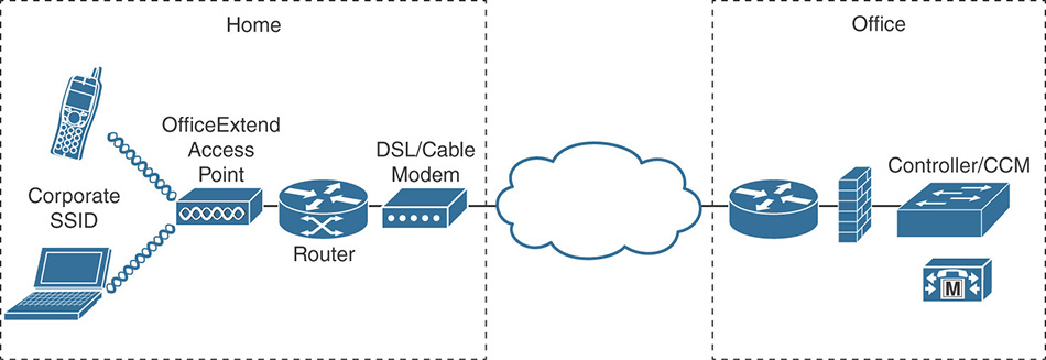
Setting an AP to OfficeExtend mode happens in the FlexConnect tab of the AP settings (the AP must be in FlexConnect mode already). You can then have a few options, like Enable Least Latency Controller, which will allow the AP to join the WLC with the lowest latency. Table 4-1 details some of the more common FlexConnect-related show commands.
Table 4-1 FlexConnect-Related show Commands
Command |
Purpose |
IOS-AP# show capwap reap assoc |
Displays all serviced WLANs on each radio with their VLAN and profile configuration |
IOS-AP# show capwap reap saved |
Shows saved FlexConnect configuration on the AP side |
IOS-AP# show run |
Shows the AP config in the style of an autonomous IOS config (allows you to verify VLAN assignments and access list) |
IOS-AP# show ip access-list |
Shows the access lists loaded on the AP |
Wave2AP# show Flexconnect wlan |
Shows the FlexConnect configuration and status of each WLAN on the AP |
Wave2AP# show Flexconnect vlan-acl |
Shows the VLAN and ACL mapping configuration on the AP |
WLC> show ap config general <Apname> |
Displays the current configuration of the given AP |
Another specificity of the OfficeExtend mode AP is that clients at the remote site will be able to reach out to the AP IP address (typically a local LAN IP) and get a web UI for the AP. This web UI shows the AP console logs (for onsite troubleshooting), allows you to set a WLC IP address (for easy provisioning), to monitor some metrics on the AP, but also to configure a personal SSID. This personal SSID will be available only on that AP and therefore is not seen on the WLC anywhere. That SSID will be locally switched at the remote site and is offered for convenience; it will not give access to corporate resources. In the Wireless > Global Configuration Settings page, you have an OfficeExtend (in the OEAP config section) specific option to prevent this local access to the AP if you don’t want remote site users to access it. There are certain AP models that will come in OfficeExtend mode and are sometimes locked to that mode (600OEAP, 700OEAP, 1810-OEAP, or 1815T); this gives the ability to order the APs, ship them to an employee’s house, and have them provision it easily by accessing the AP GUI.
Configuring and Troubleshooting Mesh
As a CCIE candidate, you are probably already familiar with mesh principles. This section can be used as a reminder of the essential concepts you need to master to face the exam. Although you are not mandated to have expertise in specific outdoor mesh AP models, you should be comfortable with setting up and troubleshooting mesh networks.
AWPP and Mesh Formation
In a Cisco network, mesh access points can have either of two roles:
Root access points (RAP) are configured to connect to the WLC using only their Ethernet connection. When deployed in the field, RAPs are used by the other mesh APs as relays to reach the wire, and through the wire, the WLC.
Mesh access points (MAP) are configured to use their Ethernet connection to reach the WLC. When such an attempt fails, the MAP uses its radio interface (5 GHz unless configured specifically to use the 2.4 GHz radio) to find a RAP (directly, or through another MAP) and reach the WLC that way.
Mesh Topologies
A consequence of this role structure is that Cisco mesh networks form trees, where the RAP is the trunk or the root, and the MAPs branches. All APs in a tree are on the same 5 GHz channel (called the backhaul), unless APs have more than one 5 GHz radio (in which case the uplink and downlink radio may be on different channel), as shown in Figure 4-30.
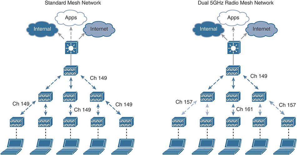
Any AP allowing another AP to pass traffic through to reach the wire is called a parent for that AP. The AP using another AP to get to the wire is the child. For example, suppose that MAP1 sends traffic through RAP1 to reach the wire. MAP1 is RAP1’s child, and RAP1 is MAP1’s parent.
If a second MAP, MAP2, goes through MAP1 then RAP1 to reach the wire, MAP2 is MAP1’s child, and MAP1 is MAP2’s parent. The relationship stops there (RAP1 is not described as “grandparent”). The network is said to have a depth of two hops (RAP1–MAP1, then MAP1–MAP2). If another AP, MAP3, also uses MAP1 as its parent, then MAP2 and MAP3 are neighbors (not “brothers” or “sisters”). In fact, any other mesh AP that can be detected and that is neither a parent nor a child is a neighbor.
In such a network, traffic flows from the MAP to the RAP first, then may be sent back to other MAPs in the tree. Traffic is never transversal. This is different from the structure described in the 802.11s amendment (dedicated to mesh networks). In 802.11s, traffic can be transversal; there can be multiple RAP equivalents (called gateways) in a given network. The 802.11s amendment was published years after most large vendors had already designed and implemented their solution, which explains why most solutions do not follow the 802.11s structure.
AWPP and Mesh Formation
When a MAP boots, it first tries to join the WLC using its Ethernet interface (if it is detected as connected). If this discovery fails, the MAP turns to its 5 GHz radio and scans all channels to discover a MAP or a RAP.
Each mesh AP connected to the WLC (as a RAP, or as a MAP through other APs) sends a status message on its 5 GHz channel every 500 ms. This message informs possible other MAPs about the link availability to the WLC, along with a value (the adjusted ease detailed later in this section) that expresses the quality of that link to the WLC. If more than one AP is detected offering such a link, the MAP will use the Adaptive Wireless Path Protocol (AWPP), a Cisco proprietary algorithm, to determine which AP offers the best path to the wire. The metric used for this protocol is a combination of hop counts and SNR between APs on the path. The result of this metric computation for each hop is called the ease value. A larger ease value typically reflects a better link. When multiple hops are combined, the adjusted ease value reflects the link for the entire path (through all the hops needed to reach the wire). The highest adjusted ease value represents the path with the best signal on each hop, for the least number of hops overall. In AireOS code releases 8.3 and later, the ease computation also includes link load values, and timers (frame travel time).
This discovery is efficient. As a CCIE, you should know how to force an AP through a specific path. However, in real life, the adjusted ease represents the best path. Forcing your AP through another path should be done only if you have good reasons to do so; a path does not become “acceptable” (from an RF standpoint) just because you force an AP to use it.
After a MAP has scanned and discovered multiple possible paths, it will choose the link offering the best adjusted ease. Once the MAP has joined the WLC, that chosen path receives an additional 20% “active path bonus” that is added to its computed ease. This mechanism prevents jumpiness, where an AP jumps back and forth between two parents of approximately the same ease value as the RF conditions change.
In a higher density network, there may be more than one mesh network in place in the same RF space. To resolve this issue, you can configure your APs, after they have joined a WLC, with a group value called the Bridge Group Name (BGN). The default value is Default.
Mesh Configuration
Configuring mesh networks is straightforward because this configuration always consist of the same steps. Advanced configurations may contain more possibilities, so make sure you master the basics before attempting nondefaults.
Mesh Basic Configuration
Your AP may already be in mesh (called Bridge) mode—you can order APs already set in that mode. When using APs in standard mode, you need to switch them to mesh mode. This mode is called on the WLC Bridge mode (we’ll use this correct terminology from now on), as shown in Figure 4-31. It is performed from Wireless > Select AP > General (CLI config ap mode bridge <ap>). Setting the AP to Bridge mode requires that the AP 5 GHz radio channel and power be set to Custom (CLI config 802.11a channel ap <ap> <any channel> and config 802.11a txPower ap <ap> 1).
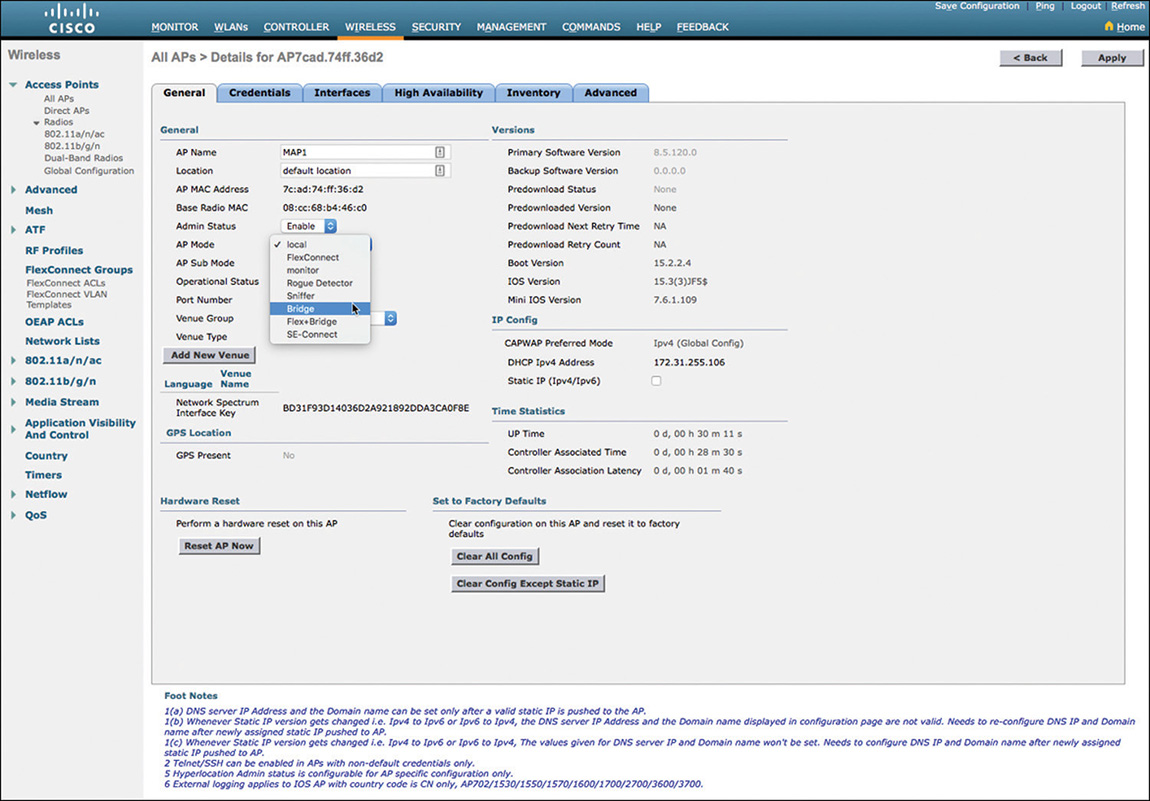
To prevent someone from attempting to have their AP join your WLC, you must authorize mesh APs on WLCs. This authorization is by default a simple MAC address filter. From the screen shown in Figure 4-32, copy the AP MAC address (which is the Ethernet interface MAC address, not the base radio MAC address). Then, navigate to Security > AAA MAC Filter and add the AP MAC address to a new filter, as shown in Figure 4-32 (CLI macfilter add <MAC, e.g. 002a10605e78> 0 none none).
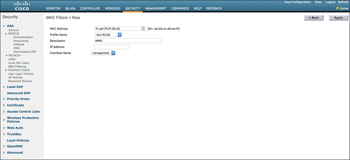
For Bridge APs, you do not need to specify a profile (keep Any WLAN). The interface name should be management. If your MAP has a static IP address, you can also use the IP address as a filter. Leave the field empty if the AP uses DHCP.
When an AP is in Bridge mode, a new Mesh tab appears in the Wireless > Select AP configuration page. All APs come by default as MAPs. To set the AP to RAP, change the mode from MeshAP to RootAP, as shown in Figure 4-33 (CLI config ap role rootAP/meshAP <ap>).
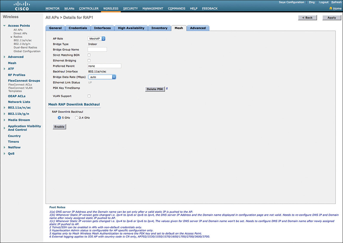
In the same tab, you can configure the BGN, which is an ASCII string of up to 10 characters (CLI config ap bridgegroupname <string>). If you configure a BGN, you can also set the AP to use only that BGN (strict matching BGN, CLI config ap bridgegroupname strictmatching) or fall back to the default BGN if no AP is found with the right BGN (no strict matching). You can also configure the backhaul radio for that AP (configure this feature only on the RAP) and set a preferred parent and the backhaul data rate. These last two elements should be configured only if you are attempting to solve a specific issue (for example, load balancing between two equally valid parents). By default, the AP chooses the best parent. If you force the AP to another parent, you may want to review your design instead, to make sure that the parent you want is also the best parent. Similarly, the AP chooses the best rate for the backhaul; if you force a specific rate, make sure that this rate is possible on that AP uplink.
Mesh Page Optional Configurations
Beyond the options relative to the AP itself, you may be asked to configure general options for the mesh network itself (in the CLI, starting with config mesh keyword). Many of these options are in the Wireless > Mesh menu, as displayed in Figure 4-34:
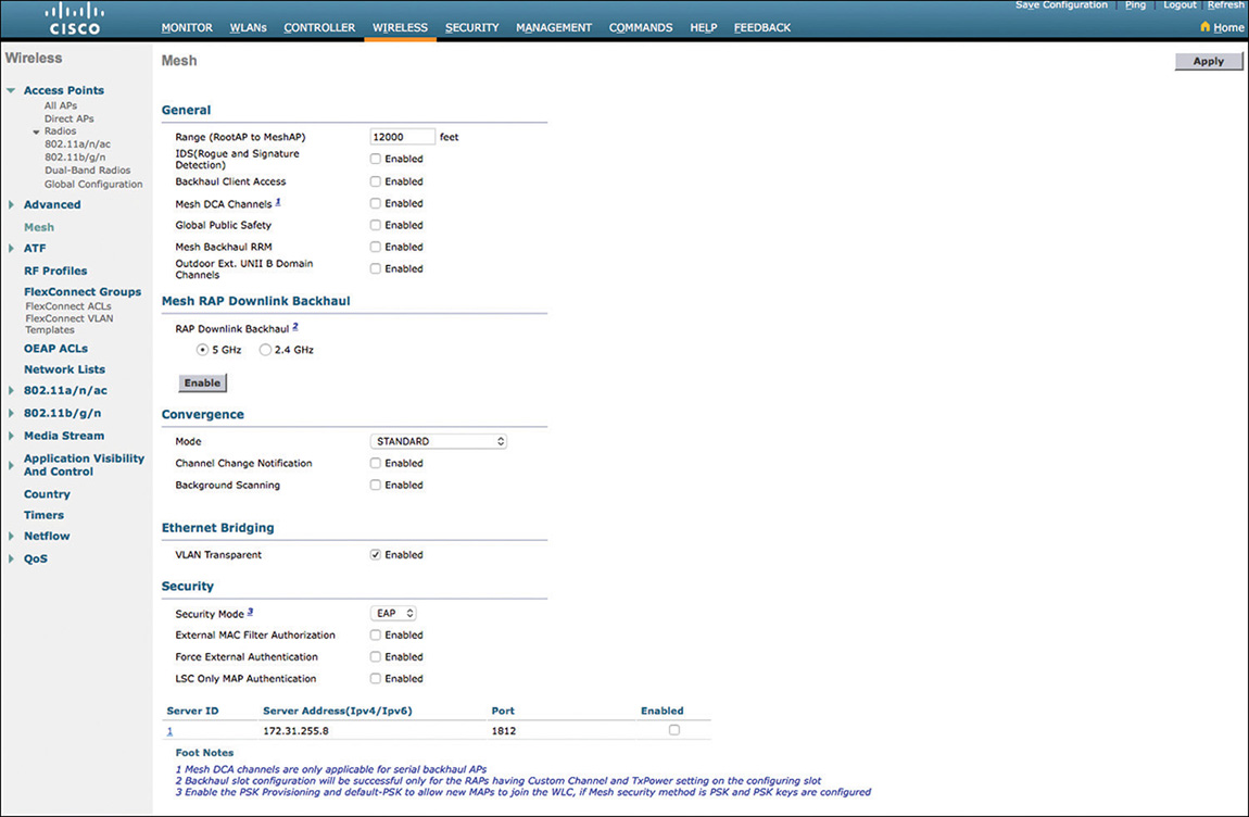
Range: In the general section, the range is useful in determining the timeout (how long after ending a message does an AP decide that the target AP is not going to respond). In a real deployment, if this value is too low, your local AP may give up before the answer has a chance to reach that local AP.
IDS is applicable only for outdoor APs. Indoor APs always perform rogue attack signature detection (just like APs in local mode). By default, this function is disabled on outdoor APs and can be enabled.
Backhaul Client Access: By default, the 5 GHz radio is used for the backhaul (AP to AP communication), and clients are on the 2.4 GHz radio. You can allow clients to also join the SSIDs on the 5 GHz radio by enabling Backhaul Client Access. A consequence of such feature is that individual clients can clog the radio that is used for multiple APs. Notice that, in the same configuration page, you can also set the backhaul to 2.4 GHz. This is useful when 5 GHz signals do not reach the MAPs properly (for example, because of foliage). If you set the RAP backhaul link to 2.4 GHz, the client backhaul access becomes 2.4 GHz as well.
Mesh DCA Channels: For indoor APs, the backhaul radio is chosen by RRM with the list built from WIRELESS > 802.11a > RRM > DCA. DFS channels are always a concern, especially in outdoor networks. This concern results in several configuration elements that seem to partially overlap:
In the DCA page, you can check the Avoid Check for non-DFS Channel option. The logic behind this option is that DCA configuration enables you to choose the channels you want to use for 5 GHz, but at least one of these channels must be non-DFS. If you choose only DFS channels, you will get a warning from the WLC. However, some countries allow DFS channels only for outdoor links. In these countries, you can check the Avoid Check for non-DFS Channel option to remove the WLC warning about non-DFS channel. You can then select only DFS channels.
Back on the Mesh tab, Mesh DCA Channel enables you to refine the channel change behavior, but only for outdoor mesh APs with dual 5 GHz radios. In case of a radar (DFS) event, RRM can change the channel. But what happens if none of the channels you selected in the DCA page are available (for example, because you selected only DFS channels and they are all hit by radar)? By default, RRM will forcefully assign another channel, even if it was not in your DCA channel list (RRM chooses this option only when it has no other choice). When selecting the Mesh DCA Channel option, you tell RRM to never choose channels outside the DCA list (again, only for dual radio outdoor APs, like the Aironet 1524SB). RRM will then rather shut down the radio than assign to a channel outside of your DCA list. This option is useful if you set a mesh link between indoor and outdoor APs. You can set the list of channels in the DCA page, and check the Mesh DCA channel option to make sure that your outdoor dual 5 GHz radio APs will not choose a channel outside that list.
Mesh Backhaul RRM: By default, mesh APs do not participate in RRM. Their channel is configured statically from the AP 5 GHz radio page, and mesh APs do not attempt to detect power optimizations of coverage holes. To enable RRM on the backhaul, check the Mesh Backhaul RRM option. This will enable the RAP (and only the RAP) to perform RRM. MAPs down the link will change their channel as the RAP changes its own channel. Note that the CLI offers additional options to the Web UI. In the CLI, config mesh backhaul rrm enable is the equivalent to the Mesh Backhaul RRM check box in the UI. However, the CLI also allows you to configure config mesh backhaul rrm <auto-rf global / off> to only activate or deactivate the DCA function of RRM for your backhaul.
Global Public Safety: This feature is useful in the FCC regulatory domains to activate the 4.9 GHz safety bands.
Outdoor Ext. UNII B Domain Channels: The FCC regulatory domain allows new channels for outdoor usage (UNII 1 channels 36, 40, 44, 48, and UNII 2 extended channel 144). UNII1 was allowed only for indoor use in the prior rules (called A domain). The FCC allows UNII1 outdoor, and a new UNII2e channel with the B domain rules. You can enable the B rules by checking this Outdoor Ext. UNII B Domain Channels option.
Convergence mode: This option is valid on AireOS code 8.3 and later. Each AP keeps track of its neighbors. When a parent is lost, detecting the loss takes time (nonresponse to a certain number of keepalive messages). Then, scanning all channels for a new parent also takes time. To expedite the process, in case of a parent loss, you can choose a different convergence set of timers. With the standard mode, an AP takes 21 seconds to detect a parent loss, then scans all channels to find a better parent. With the Fast mode, the AP waits only 7 seconds to decide that a parent is lost (1 second after sending the third keepalive at a 3-second interval). The AP then scans only the channels for which it detected neighbors in its own BGN. With the very fast mode, keepalives are sent at 1.5 second intervals, and the AP detects the parent lost within 4 seconds. The AP also scans only the channels for which it detected neighbors in its own BGN. With the Noise Tolerant fast, the AP operates as in the very fast mode, but waits longer after each keepalive before deciding that it received no answer and retries each keepalive. In a lab environment, the decision is about speed or stability. A faster mode allows for faster convergence, but the next parent chosen may not be the best, resulting in a potentially unstable uplink (and the risk of losing that new parent).
Background Scanning: How would an AP know its neighbors? By default, the AP learns about them during the initial scanning phase. By the time the parent is lost, which may be days after the initial join phase, these neighbors may have changed channels or have disappeared. If you want your AP to maintain a fresh list of neighbors, check the Background Scanning option. In this mode, the AP will leave its backhaul channel every 5 seconds to go scan to neighbor channel information refresh. The advantage is to maintain a fresh list of neighbors, but the downside is that you may be disrupting the traffic on the backhaul, because the AP is away at regular intervals.
Channel Change Notification: By default, a mesh AP changes its channel silently. The other APs that may depend on that channel will have to scan and discover the AP again. If you enable mesh backhaul RRM, or if you change the AP channels often, you may want to enable the Channel Change Notification feature. When the AP changes channel, it informs its children and parents through CAPWAP.
Mesh Security Configurations
Authorizing your mesh APs to join the WLC is a key component of the deployment task. During the discovery phase, a MAP will scan channels, discover the AP with the best Ease value in its Neighbor Update messages, and then authenticate to the RAP. This phase is used to ensure that the backhaul link is encrypted. This authentication can be done using EAP-FAST, leveraging the AP’s certificates (default). However, you may want to use PSK instead. This is useful if your AP is an old model with LSC certificates, or an expired certificate, or if you are unable to provide a proper clock synchronization to your system. You can change the authentication to PSK from the Wireless > Mesh > Security section (CLI config mesh security psk). You then have to set the PSK. You should be aware that your APs first must join the WLC so that they can be provisioned with the PSK. They will then use PSK on their next join attempt. If new APs join a PSK-based system, authentication will fail, as the new AP does not know the PSK. To prevent this issue, choose the Default PSK option, allowing the new AP to use a factory-built value for the PSK and join successfully, even if the PSK you configured on the WLC is unknown to the new AP. In that case, you may also want to choose PSK provisioning, to push the new PSK value to the joining AP. Using these two options allows any Cisco AP to join your WLC. You would enable them only when new APs are expected to join the mesh.
One confusing aspect of this authentication to the RAP is that the goal is to encrypt the mesh backhaul. However, the RAP is not an authentication server. During the authentication phase, the RAP relays the query to the WLC, and the WLC is the entity performing the authentication validation. However, at this point, the WLC is not authenticating the MAP directly; it is merely validating the requests from the RAP so as to enable backhaul link encryption. The MAP has not joined the WLC yet.
After encryption to the RAP is achieved, the MAP uses the backhaul link to send CAPWAP messages to the WLC. At this point, the WLC needs to authenticate the MAP. The authentication can use a MAC address filter configured on the WLC, as described earlier in this section. In some cases, it may not be practical to use such a MAC filter. A typical example is mining operations where APs are moved between sites, and a single AP may end up on any number of local controllers. Entering all the MAC addresses of all possible APs on all WLCs is inefficient in this context. In this environment, you can set the MAP to authenticate using only its certificate, by checking the LSC only MAP Authentication (CLI config mesh security lsc-only-auth). The WLC will then validate the AP certificate but ignore the MAC address filter.
Note
Using LSC on a mesh network implies deploying local certificates to your mesh AP; it is not an expected default option in most networks. Refer to the following document for more details on LSC configuration for mesh APs:
You can also use an external RADIUS server to authenticate your mesh APs. This is achieved by checking the option External MAC Filter Authorization. In that mode, the WLC relays the AP authentication query to a RADIUS server configured on the WLC (from the global RADIUS Servers list). The RADIUS server must be configured to use EAP-FAST with certificates to accept the AP queries.
For each AP, you also need to add a new user to the RADIUS database, with the name being the AP MAC address (for example, aa-bb-cc-dd-ee-ff) and the password being the same MAC address value. Additionally, for IOS APs, you must add a second user entry, with the name being the platform and Ethernet MAC address (for example, c1520-aabbccddeeff) and the password cisco.
When a mesh AP attempts to join the WLC, the local MAC address filter list is checked. If the mesh AP MAC address is not found, the WLC relays the query to the RADIUS server. The mesh AP is then authenticated there using EAP-FAST and the mesh AP certificate. This mode mandates that you use EAP as a security mode.
If you want to completely bypass the local WLC MAC filter list, you can also check the Force External Authentication option. In that case, the WLC local list is completely ignored.
Mesh Local Bridging Configurations
Local bridging has long been a salient feature of mesh networks, allowing devices connected to your MAP to send traffic through the backhaul. The original use case was about street cameras, but many deployments ended up connecting switches and entire networks to these MAPs. The requirements of local bridging became so close to FlexConnect local switching that both modes were merged for Mesh networks in WLC code AireOS 8.0. The result is that both modes are often confused.
Without Flex configuration (that is, when your APs are configured in regular Bridging mode), you can enable Local Bridging on the AP. For each AP on the link, enable Ethernet Bridging in the AP Mesh configuration tab. This must be done on all APs on the link (if MAP2 uses MAP1 to reach RAP1 and you need to relay traffic from a camera connected to MAP2 Ethernet interface, you need to enable Ethernet bridging on MAP2, MAP1, and RAP1). This function is disabled by default to prevent anyone from connecting something to your mesh APs and sending traffic over the backhaul.
If your APs connect to switches on a trunk port, you also need to enable VLAN support for these APs. Check the VLAN support option and click Apply. When you come back to that same page, you can decide the native VLAN value, and also click the Ethernet interface at the bottom of the screen to configure the VLANs you need supported across the AP interfaces (radio and Ethernet). This configuration is not always needed on the MAP if it connects to an access port; however, it is often needed on the RAP. You should also keep in mind that enabling Local Bridging does exactly what the name implies: when traffic coming from the backhaul reaches the RAP, it is bridged locally (that is, not forwarded to the WLC).
In addition to this regular local Bridging function, you can enable the AP to operate in Flex+Bridge mode. The main features of this mode are represented in Figure 4-35.
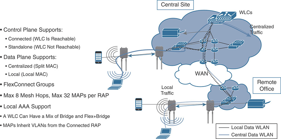
In this mode, local bridging is also allowed but for the wireless clients connecting to the RAPs and MAPs (in the local Bridging feature previously explained, the local bridging was only for wired devices connected behind MAPs’ Ethernet ports). In addition, a new FlexConnect tab appears that includes the VLAN support option (moved from the Mesh tab). In this Flex+Bridge mode, you can decide whether your VLAN configurations are local to the AP or are global. If the VLAN configuration is expected to be global, you should check the Install mapping on radio backhaul to apply that mapping to the other APs and the backhaul. In that case, you only need to configure the mapping on the RAP.
You can also configure from the same tab FlexConnect features such as WLAN to VLAN mapping (including local switching for WLANs), local split ACLs, and so on.
An advantage of the Flex+Bridge mode is that the AP now supports loss of connectivity to the WLC. In standard bridging mode, the loss of connectivity to the WLC is a major issue that stops the mesh operation. In Flex+Bridge mode, loss of connectivity to the WLC pushes the AP to a standalone mode similar to FlexConnect. RAPs continue to bridge traffic. A MAP maintains its link to a parent and continues to bridge traffic until the parent link is lost. However, an AP cannot establish a new parent or child link until it reconnects to the WLC. Existing wireless clients on the locally switching WLAN can stay connected with their AP in this mode. Their traffic will continue to flow through the Mesh and wired network. No new or disconnected wireless client can associate to the Mesh AP until the WLC connectivity is back.
Troubleshooting Mesh
Proper mesh operations can be verified from the WLC UI, from the Neighbor Information option, found in the blue chevron of an AP line in Wireless > All APs. The neighbor information is shown in Figure 4-36. You can get the same information from the CLI (using show mesh family of commands).
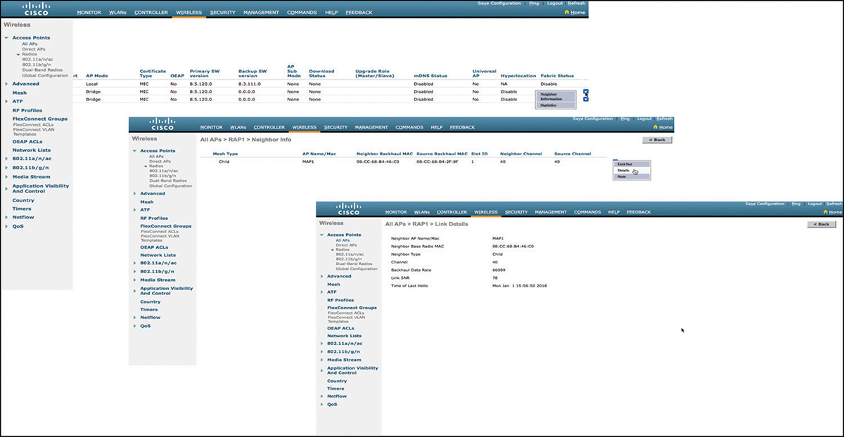
From these pages, you should be able to verify neighbor relationships, parent-children links along with transmitted frames, and signal quality. In most cases where issues affect APs that have already joined, these pages will help you determine why an AP did not choose the path you designed, or why APs form a different relationship from the one you expected.
In real life, multiple issues may affect your mesh network. In the lab, beyond link and RF problems, the most common issue for mesh is an AP failing to join. You should be aware that mesh convergence takes time. It is not uncommon for an AP to need 5 to 10 minutes to join the mesh network in a noisy environment. While you wait, the first verification should be about AP authentication.
You should use the debug mesh family of command for any mesh issue. Example 4-1 focuses on the join issue and shows the commands you can use and a typical output.
Example 4-1 Debugging Mesh Events
(Cisco Controller) >debug mesh ?

alarms         Configures the Mesh Alarms debug options.
astools        Configures debug of mesh astools.
message        Configures the Mesh Message debug options.
security       Configures the Mesh Security debug options.

(Cisco Controller) >debug mesh security ?

all            Configures debug of all mesh security messages.
errors         Configures debug of mesh security error messages.
events         Configures debug of mesh security event messages.

(Cisco Controller) >debug mesh security events enable
(Cisco Controller) >*spamApTask4: Jan 01 16:20:17.673:  08:CC:68:B4:2F:80
  Request MAC authorization for AP Child Addr:  08:cc:68:b4:46:cf AP Identity:
  7c:ad:74:ff:36:d2 AWPP Identity: 08:cc:68:b4:2f:8f
*spamApTask4: Jan 01 16:24:04.095:  08:CC:68:B4:2F:80 MESH_ASSOC_REQUEST_PAYLOAD in
  Association Request for AP 08:CC:68:B4:46:CF
*spamApTask4: Jan 01 16:24:04.095:  08:CC:68:B4:2F:80 Mesh assoc request for known
  AP 08:cc:68:b4:46:cf
*spamApTask4: Jan 01 16:24:04.095:  08:CC:68:B4:2F:80 Mesh assoc request :child :
  08:cc:68:b4:46:cf NextHop : 7c:ad:74:ff:36:1a  LradIp 172.31.255.113  vlanid: 31
  mwarPort: 5246  lradPort: 62306
*spamApTask4: Jan 01 16:24:04.095:  08:CC:68:B4:2F:80 Request MAC authorization for
  AP Child Addr:  08:cc:68:b4:46:cf AP Identity: 7c:ad:74:ff:36:d2 AWPP Identity:
  08:cc:68:b4:2f:8f
*spamReceiveTask: Jan 01 16:24:04.097: MAC Validation of Mesh Assoc Request
  for08:cc:68:b4:46:cf is -9, Mode is : 0
In Example 4-1, the MAC address of the MAP was removed from the WLC MAC filter. The same effect would appear if the AP was removed from the RADIUS (but you would also see RADIUS logs). As a result, the MAP is known, but its association request shows −9 (which is a “no”). In the WLC SNMP traps, you also see the following:
AAA Authentication Failure for Client MAC: 08:cc:68:b4:46:cf
  UserName:7cad74ff36d2  User Type: WLAN USER Reason: unknown error
What you should see instead is the following:
(Cisco Controller) >debug mesh security events enable
*spamApTask4: Jan 01 16:31:36.938:  08:CC:68:B4:2F:80 MESH_ASSOC_
  REQUEST_PAYLOAD in Association Request for AP 08:CC:68:B4:46:CF
*spamApTask4: Jan 01 16:31:36.938:  08:CC:68:B4:2F:80 Mesh assoc
  request for known AP 08:cc:68:b4:46:cf
*spamApTask4: Jan 01 16:31:36.939:  08:CC:68:B4:2F:80 Mesh assoc
  request :child : 08:cc:68:b4:46:cf NextHop : 7c:ad:74:ff:36:1a
  LradIp 172.31.255.113  vlanid: 31  mwarPort: 5246  lradPort: 62306
*spamApTask4: Jan 01 16:31:36.939:  08:CC:68:B4:2F:80 Request MAC
  authorization for AP Child Addr:  08:cc:68:b4:46:cf AP Identity:
  7c:ad:74:ff:36:d2 AWPP Identity: 08:cc:68:b4:2f:8f
*spamReceiveTask: Jan 01 16:31:36.940: MAC Validation of Mesh Assoc
  Request for08:cc:68:b4:46:cf is 0, Mode is : 0
Validation is 0, meaning that the AP successfully passes the association phase (0=success) and moves to the PMK exchange phase.
A second possible key issue is about IP addressing. APs join a mesh network based on RF links. This may result in an AP using a backhaul path different from the one you designed, using a different RAP. This can be a problem if the RAP is in a different subnet than in your design, and if the MAP has a static IP address (that may end up in the wrong subnet). By default, the AP will revert to DHCP if it can’t join using its static address. Remember that the MAP does not need any IP connection to establish a secure link to the RAP, but will need IP connectivity to join the WLC successfully. If APs are very slow to join, verifying the IP addressing scheme should be one of your troubleshooting steps.
In real life, there may be many options that would need to be enabled for a mesh network. In the lab, however, the main purpose of the configuration is to verify your understanding of the central issues, and the elements covered in this section of the chapter should help you make your way through the mesh section.
Radio Frequency Management
This section encompasses all the settings on the WLC pertaining to radio frequency parameters—whether they are static or managed through the Radio Resource Management (RRM) algorithm.
What Problem Are We Trying to Solve?
Without getting back too much into the RF Layer 1 theory again, two main things can be tweaked to optimize a wireless deployment: transmit power and channels used. Of course, the most important is the physical placement of APs and antennas and overall design, but that is not part of the CCIE wireless lab exam. After a network is up, it mostly boils down to changing the power and the channel of APs to achieve the best efficiency possible depending on your requirements and current deployment.
The 2.4 GHz band is typically straightforward, despite the availability of 11 (or 13 or 14, depending on country) channels, you can only use 3 because we definitely want to use non-overlapping channels to avoid adjacent-channel interference. There is a global agreement that channels 1, 6, and 11 are the best to use. (Although some people try a 4-channel plan with 1, 5, 9, and 13, this is not recommended for all deployments and is anyway restricted to countries where more than 11 channels are available.) The 5 GHz band doesn’t have such restriction, and you can basically pick any channel you like because they do not overlap. However, 802.11n brought 40 MHz channels and 802.11ac brought 80 MHz channels, which adds a layer of complexity to the channel plan. 40 MHz channels include a “primary 20 MHz channel,” which means that if an AP declares to be on (36, 40), all management and control frames are sent at 20 MHz width on channel 36, for example, and clients are allowed to send 40 MHz wide data frames on both 36 and 40. So 36 serves as primary channel for all the nondata frames as well as clients who might not support 40 MHz. The concept is the same with 80 MHz, where there is a primary 20 MHz channel (for all nondata frames) and a primary 40 MHz channel (for clients who might not support 80 MHz). For example, an AP declaring to be on (40, 36, 44, 48) has the primary 20 MHz channel on 36, the primary 40 MHz on 36 and 40, and the 80 MHz spanning from 36 to 48. The concept is illustrated in Figure 4-37.
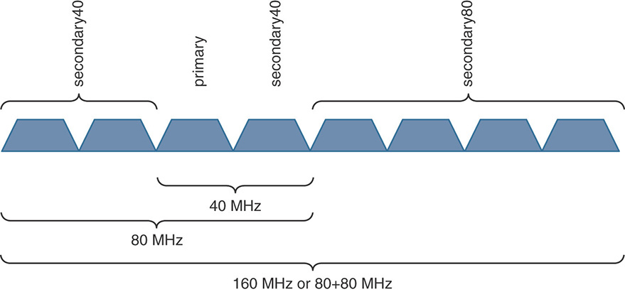
This means that the primary 20 MHz must not necessarily be the first channel in ascending order, which in turn means that you could imagine an AP on “(40,36)”, which would have its primary channel on 40 and another AP close by on “(36,40)”, which would have its primary channel on 36. Both would have to share medium when sending 40 MHz data frames but could send 20 MHz management frames at the same time because they would then be on different channels. This is not optimal (it’s best to have them fully on separate channels) but this is something that can be done. Secondary channels have different Clear Channel Assessment (CCA), depending on the client standard (802.11n or 802.11ac), which changes the received signal strength value at which a station can consider the medium to be free to transmit. All of this makes it harder and harder to fully design a channel plan statically in a mixed real-life environment.
Because the 2.4 GHz wavelength tends to cover a greater distance for an equal modulation, and because designs are typically made with 5 GHz in mind, newer deployments typically have too many 2.4 GHz radios and with only three available non-overlapping channels (that are possibly sharing the air with Bluetooth, microwaves, or any other IoT kind of device), it has become a “best effort” band. There are still single band wireless clients, so it might still be desirable to provide 2.4 GHz coverage for those, at least in specific areas, but no one talks about high density with 2.4 GHz because this is impossible due to the lack of channels. The 2.4 GHz band is still very useful for RFID and tags location tracking as well as other IoT usage, though, but 5 GHz will take most of the requirement with regard to video and audio streaming, real-time applications, and bandwidth-intensive applications.
The 5 GHz band still has a few tricks to clarify, though. Only channels 36 to 48 are strictly non-DFS channels in every country. Most (and often all) of the others are DFS regulated channels (in most countries, with exceptions), which means that an AP arriving on that channel will have to wait one minute to make sure there is no radar on that channel; it can then transmit beacons. Clients don’t need to do this check if there is an access point already beaconing on that DFS channel. The DFS regulation enforces 10 minutes wait time on channel 120 to 128 before an AP can beacon, rendering these three channels very impractical, and many APs do not support them for this reason. Support on the client side also differs greatly; more and more clients support more and more of the UNII-2 extended channels, but it’s unrealistic to hope that all your clients will support all the channels that your AP might support. Over the years, more channels become available in some countries (like channel 144 currently) but it will take many more years for clients to support these channels.
Static Assignment
The WLC allows you to configure each radio of each AP in a static manner or to leave it managed by the RRM algorithm (as illustrated in Figure 4-38). When the radio has static assignments, the little asterisk next to it disappears, meaning that the radio assignment is not managed by RRM anymore. The channel, channel width (20, 40, 80, 160), and transmit power can be assigned manually (as shown in Figure 4-39).
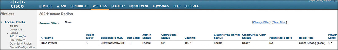
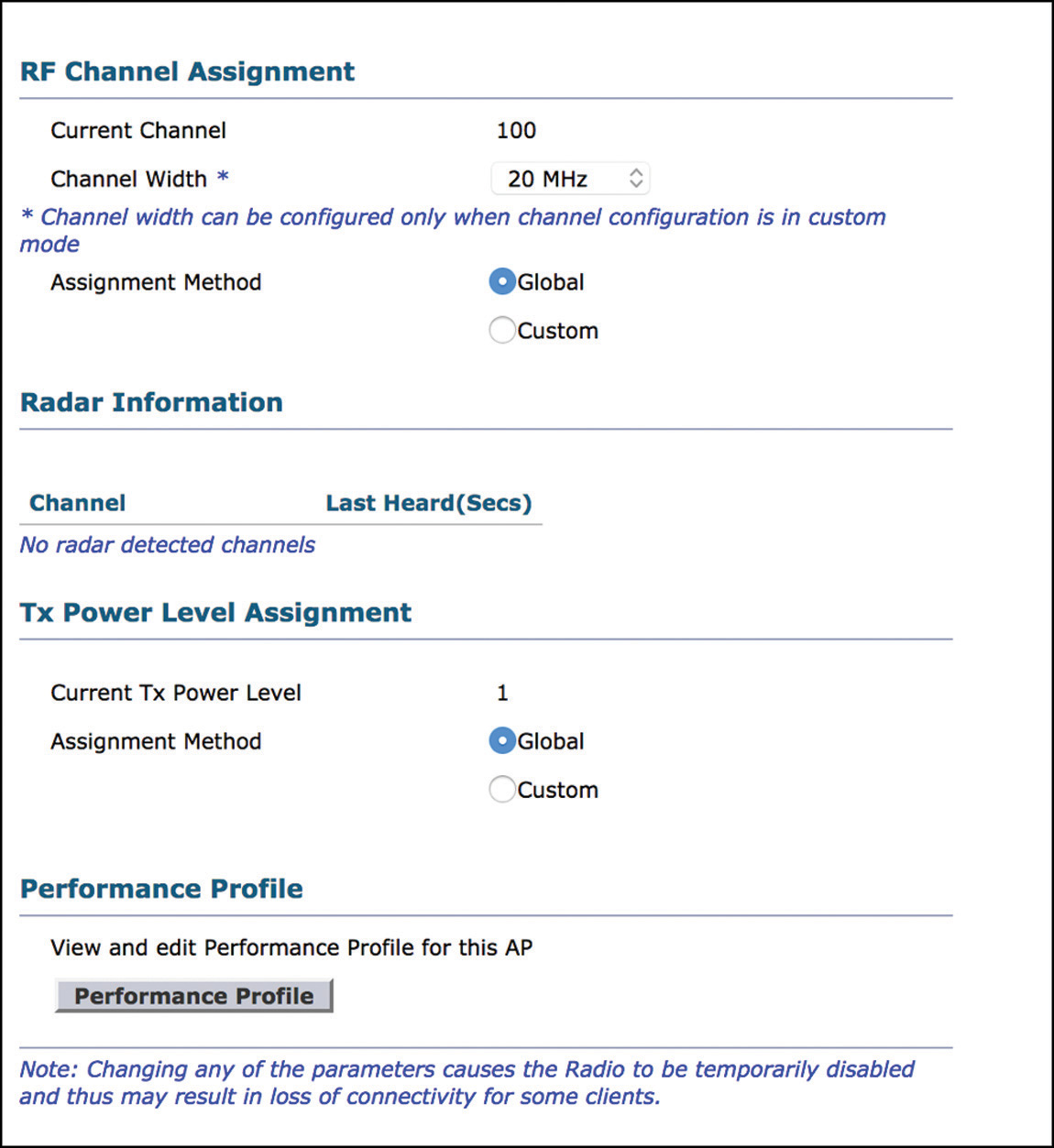
Global Assignment (RRM)
The RRM algorithm is actually several separate and mostly unrelated algorithms, each taking care of one specific functionality:
Transmit Power Control (TPC) is in charge of decreasing the transmit power of specific AP radios in case there are several APs very close to each other (which would then interfere with each other).
Coverage Hole Detection algorithm (CHD or CHDM) is in charge of increasing the power of radios (so the complete opposite of TPC) if there are several clients that stick to that radio at a poor signal strength.
Dynamic Channel Assignment (DCA) is in charge of choosing the best channel for each AP radio, taking all surrounding radio channels as well to come up with the most optimal channel plan.
Flexible Radio Assignment (FRA) is a newer addition to RRM and takes care of APs with flexible XOR radios (2800, 3800, 4800 at the time of this writing). It will decide whether there are too many 2.4 GHz radios providing client coverage and either turn some into monitoring radios or 5 GHz clients serving.
But before diving into these algorithms, it is important to understand based on what metrics all those algorithms make their decisions. APs are involved in some data collections activities regardless of the algorithms that are enabled or configured, and it’s with these data that the RRM algorithms will make their decisions.
Off-Channel Scanning
In a nutshell, APs will go off their client-serving channel to scan very briefly other channels and will also send a neighboring packet to help neighboring APs discover and learn about them. In the Wireless> 802.11a/b > RRM page (shown in Figure 4-40), we can set the channel list for monitoring channels (for noise, interference, rogue, and CleanAir).
If set to Country Channels, the APs will scan and send discovery neighboring packets on all the channels supported officially in the country (regardless of whether you restricted the channel list for DCA).
If set to All Channels, the APs will scan on all the channels that their hardware supports. This includes channels not supported in the configured country; however, the AP will only passively scan (that is, listen) there and cannot transmit on those channels (to avoid violating laws).
If set to DCA Channel List, the AP will only scan and send discovery neighboring packets on channels configured in the DCA list (that is, the list of channels we configured the AP to pick from). This typically would restrict the AP scanning channels 1, 6, and 11 on 2.4 GHz because it’s common to have only those three enabled for the AP to pick from. The result is that your APs will not detect any rogue that would be present on channels 3 or 9, for example.
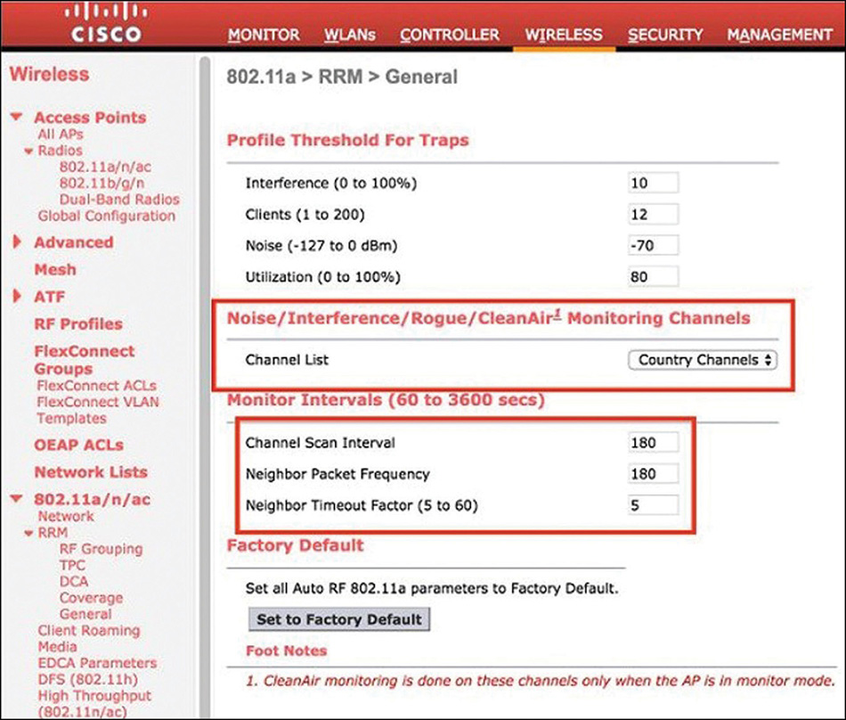
Figure 4-40 RRM Settings Page
The same page allows you to set the timers for those scanning activities in the Monitor Intervals section. The Channel Scan Interval field refers to the passive dwell activity. We already hinted a bit in the previous paragraph, but this defines in which interval the AP must complete its passive scanning of all the configured channels (DCA, country, or all channels). The radio will spend 50ms on that channel to passively listen for rogues, collect noise, and interference metrics. This means that for a bit more than 50ms (because the radio must change channel and this takes a few ms) the AP is outside of its channel (unavailable) without any means to warn clients about it. This time is usually small enough for clients to try to retransmit their frames and not go crazy about the AP not responding anymore. To give two examples, if we configured APs to scan the DCA channel list on 2.4 GHz, which would mean channels 1, 6, and 11, then the AP has 180 seconds (because the monitoring interval is set to 180 seconds by default) to scan those three channels. This implies that the AP will leave its channel every 60 seconds to scan another channel. If on 5 GHz, there are 22 channels to scan in most countries, which means that the AP will scan another channel every 8.18 seconds in order to be done within 180 seconds.
Right under the monitoring interval is the Neighbor Packet Frequency option, which is similar. It defines the interval of time in which the AP must be done sending a Neighbor Discovery Packet (NDP) on each of the monitoring channels (provided they are allowed in the country; otherwise it cannot transmit there).
NDP packets are sent to a multicast destination address for all other APs to hear. They are sent at the highest power allowed for the channel and band (regardless of any configuration you may do) and at the lowest data rate supported in the band (regardless of what you configured as well). They allow each AP to build a list of Rx Neighbors (how they hear other APs) and Tx Neighbors (how other APs hear that one). The Neighbor Timeout factor setting in the RRM page allows you to define after how many Neighbor packet frequency (180 seconds by default), the AP must delete a neighbor AP if it didn’t hear it anymore. For example, if you choose 5, it means that the neighbor AP has 5 opportunities (5 times 180 seconds) to send an NDP on “your” channel before you delete it as a neighbor. What is the purpose of this feature? There might be reasons for an NDP packet to be postponed: maybe the medium is busy, but if there is a voice SSID on that neighbor AP and because Off Channel Scan Defer is enabled by default for UP 4, 5, and 6 on the WLAN settings, it means that the AP will postpone NDP transmission (and even scanning activity) until voice calls are over, which may definitely take some time. We do not want to prematurely delete APs from an RF neighborhood just because they were prevented from sending an NDP packet. It is interesting to note that NDPs will not be sent on DFS channels where no APs have been heard, because DFS regulations normally require an AP to monitor the channel for 1 minute before sending something on it.
When the AP has an extra monitoring radio (3600, 3700 with the monitoring module, or a 4800), that third radio is doing all the off-channel scanning activities (including transmitting and listening for NDP packets).
RF Grouping
The NDP packets allow APs to hear each other over the air and identify other APs channel and transmit power settings, but there must be some kind of grouping. It is not because two APs are Cisco models and hear each other that they necessarily belong to the same deployment.
The RF group settings in the general controller settings allow for some administrative grouping: your APs will not try to discuss with your neighbor company’s APs. You can decide whether to configure the same RF group on the various WLCs you own, depending on whether you want APs from each WLC to take others into consideration. Inside each RF group, there is also a concept of RF neighborhood. Indeed, there is little point for APs that are in separate buildings and incapable of hearing each other to work together on a channel plan. An RF neighborhood determines a group of APs that hear each other at −80dBm at least (they don’t necessarily need to hear each of the APs in the RF neighborhood, but there should always be a way to relate all APs in the neighborhood through other neighbor APs belonging to the group). This allows for an algorithm to run on smaller groups of APs that should care about each other, as shown on Figure 4-41.
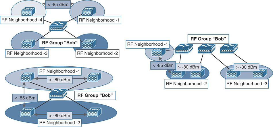
Each RF group (which can span, or not, through multiple WLCs) must elect an RF group leader, which will be the WLC responsible for the RF configuration, running the RRM algorithms, and collecting and storing the RF data and metrics. There is an RF group leader per frequency band. It can be the same WLC, but not necessarily (some APs can hear each other on 2.4 GHz but not on 5 GHz, so even the RF neighborhoods might not be the same). The RF leader is elected based on a combination of the WLC model (the higher the model/capacity, the higher the priority) and the IP address. The first condition for this to happen is that APs of different WLCs must hear each other over the air; then the WLCs must be reachable via the wired network (UDP 12134->12124).
It is critical to understand that the RF leader will make the RF decisions; therefore, it is on the RF leader that the settings will definitely matter. The RF grouping page, illustrated in Figure 4-42, lets you know who the RF leader for each band is and how many APs are part of it, and lets you override the RF leader selection manually if desired.
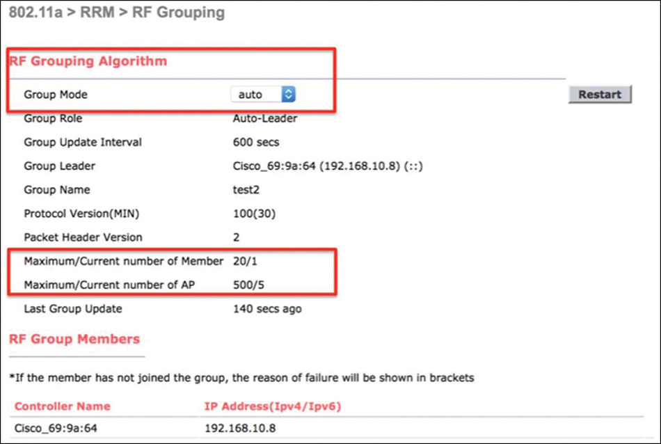
Flexible Radio Assignment
2800, 3800, and 4800 APs have a flexible XOR “slot 0” radio. It starts as a classical 2.4 GHz radio but can switch to 5 GHz or monitor both bands. Flexible radio assignment (FRA) first measures the coverage overlap factor (COF); that is, the amount of superfluous 2.4 GHz radios that could be turned off without impacting coverage. It then manages the radio roles of those APs with high COF, to either switch them to 5 GHz client serving or full dual-band monitoring. Finally, it also takes care of the load balancing of clients between the two 5 GHz radios in a micro/macro cell scenario.
FRA runs with the same RRM metrics (mostly NDP packets) as other algorithms, and it takes all previous (non-XOR) AP models into account to determine the 2.4 GHz coverage overlap factor. However, for now only the 2800/3800/4800 AP radios can be marked as superfluous and their role changed. The COF is the percentage of the analyzed cell that is covered at −67dBm by other existing radios in service. So, if the COF of an AP is 100%, it means its 2.4 GHz radio can be disabled without any loss of coverage (in fact, it will even lower same-channel interference and will improve your airtime availability). The FRA page (illustrated in Figure 4-43) allows you to configure the COF threshold. At Low, it will mark as redundant radios with a 100% COF; at Medium, it will mark as redundant radios with a 95% COF, and it will be 90% for the High setting.
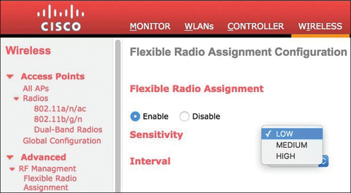
When a radio is redundant, FRA will try to make it a 5 GHz client serving radio unless DCA determines there are already too many 5 GHz channels used. If DCA considers there is already enough 5 GHz coverage, it will switch the radio to dual-band monitoring. It is interesting to note that when a radio was switched to 5 GHz client serving, it does not participate anymore in COF calculation (it does not scan or send NDP packets on the 2.4 GHz band anymore), so this role change cannot happen back and forth—once it moves to 5 GHz it does not come back. This is improved in 8.5 or later software, with a threshold determining at how many 2.4 GHz clients we consider we need a radio back in the 2.4 GHz. The AP settings page will allow you to select the automatic FRA or manual assignment as shown in Figure 4-44.
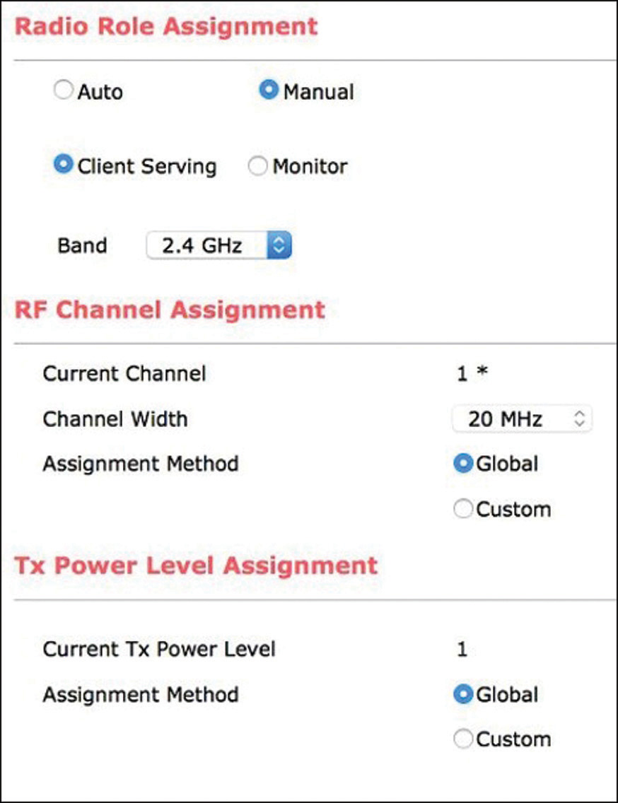
Out of the box (that is, without a DART connector), the 2800 and 3800 APs can have only one set of dual-band antennas (internal or external). This presents some limits to what is achievable: that is, set two radios on the same frequency band using the same physical antennas. In this case, the AP forms what we call a macro/micro cell: one radio transmits at a high transmit power and the other radio at the smallest transmit power. They also pick channels with a separation of at least 100 MHz to prevent signal interference. The name macro/micro means one of the 5 GHz radios will have a large coverage and the other a small coverage area. 2800 and 3800 APs have a DART connector that allows plugging in another set of external antennas. In that scenario, because each radio can use a different set of antennas, they can both perform at any power level. This setup is called a macro/macro cell: the two radios then act independently as usual.
In the micro/macro cell, the macro cell is where clients connect first when they arrive in the coverage area, and if there was no special mechanism, there is a good chance many clients would stay connected to that macro cell because it has the strongest signal. Instead, the macro radio will use 802.11v to direct clients that are very close to the AP to the micro cell radio. This has many advantages: the micro cell is used only by clients with a strong signal that can use high modulations and will most likely not have a lot of retries. When clients move further away again, they can be handed over to the macro cell again. The parameters of the steering of clients between the micro and macro cell can be verified and changed as illustrated in Example 4-2, along with FRA-related commands shown in Table 4-2.
Example 4-2 Client Steering-Related Commands
(Cisco Controller) >show advanced client-steering

Client Steering Configuration Information
1  Macro to micro transition threshold............ -55 dBm
2  micro to Macro transition threshold............ -65 dBm
3  micro-Macro transition minimum client count.... 3
4  micro-Macro transition client balancing win.... 3

(Cisco Controller) >config advanced client-steering transition-threshold ?

balancing-window Configures micro-Macro client load balancing window
macro-to-micro Configures Macro to micro transition RSSI
micro-to-macro Configures micro to Macro transition RSSI
min-client-count Configures micro-Macro minimum client count for transition
802.11v BSS Transition – enabled by default
Table 4-2 FRA-Related Configuration and Verification Commands
Command |
Purpose |
WLC> show advanced FRA |
Displays all the FRA settings |
WLC> show advanced client-steering |
Shows all the macro/micro cell client-steering settings |
WLC> config advanced fra revert all auto |
Reverts all APs to auto FRA configuration |
WLC> config advanced fra enable |
Enables FRA globally |
Dynamic Channel Assignment
Dynamic channel assignment (DCA) will adjust the channels of APs in an RF group to optimize performance. It uses an RSSI-based metric, but its calculation function is not publicly disclosed. A subcomponent of DCA is Dynamic Bandwidth Selection (DBS), which can select the best bandwidth (20, 40, 80, 160) for each AP if the bandwidth setting is set to Best, as illustrated in Figure 4-45.

The DCA page in the controller (Wireless > 802.11a/b > RRM > DCA) allows you to enable or disable certain contributors to the calculated RSSI metric.
Foreign AP interference: DCA will include the interference caused by APs not belonging to the RF group (i.e., rogues).
Non Wi-Fi noise: This includes CleanAir-captured interferers in the channel decision.
Cisco AP load: This includes the load caused by APs on the same channel belonging to the RF group (non rogues).
Persistent non-Wi-Fi interference: This also depicts interferers detected by CleanAir but only targets persistent ones; that is, interferers that may not be present at any given time but were identified to be recurring enough to cause a problem.
The same page also allows you to enable which channels DCA will pick from to assign to the APs. The algorithm will run when set to Automatic; you can then set an interval and anchor time. It will run every <interval> minutes starting from the anchor time. You can, for example, make it run every 6 hours starting from midnight (which would be the same as setting it anchored at 6 a.m. or noon; it will run at midnight, 6 a.m., noon, and 6 p.m.). If set to Freeze, the algorithm will not update channels anymore unless you click the update button next to it, but the NDP packets and off-channel scanning will continue to happen (to collect metrics). If set to Off, it will not run, and metrics collection activities will stop. You can see who the RF leader is, when the algorithm last ran, and set the sensitivity of the algorithm in dB (the calculated nondisclosed RSSI-based metric). If you chose a channel width, that same width will be used on all APs, but if set to Best, the width can be different on all APs.
When a WLC reboots, even if it is not the RF leader, the DCA algorithm will switch to startup mode in the RF group. In startup mode, the DCA algorithm runs every 10 minutes for 100 minutes, regardless of what the configuration is. When an AP reboots, it starts using its last saved channel setting, or if it’s a new AP it will start on the first available channel (1 and 36).
ED-RRM is often associated to CleanAir but it’s truly event-driven RRM regardless of CleanAir. It will decide channel changes outside the normal DCA interval if there is a sudden event (and typically based on CleanAir interferers) that changes the metrics. If you enable rogue contribution, the EDRRM can also make these sudden decisions based on rogue presence (which is not a CleanAir-based metric). The last option in EDRRM is the rogue duty cycle that enables the channel change if an existing rogue suddenly uses more air time than the percentage configured.
Coverage Hole Detection and Mitigation (CHDM)
The coverage hole function is the only one to run on every WLC (regardless of RF leader). This is because it does not need to take many factors into account: The idea is that if several clients stick to one AP at a low signal strength, and this AP is not already at the maximum power, we should then increase its power level. A precoverage hole event happens if a single client stays for 5 seconds under the configured RSSI at the AP level. However, the precoverage hole event is only for tracking purposes, and only an SNMP trap is sent. If the configured number of clients stay under this threshold RSSI for more than 90 seconds, an actual coverage hole happens and actions are taken.
The default values are that you need at least three clients (the Min Failed Client Count Per AP setting) and they must represent 25% of the client count of the AP (coverage exception level per AP) for a coverage hole to be declared. This means that on default settings, the AP will only declare a coverage hole if it has, say, 12 clients, out of which 3 or more are under the RSSI threshold for more than 90 seconds. This threshold is configurable but is −80dBm by default for data and −75dBm for voice. Note that these RSSI settings are also used for optimized roaming features as explained later in this chapter.
Coverage hole can be enabled on a per-WLAN basis. However, it is the detection that is enabled or not for a given WLAN; the mitigation (that is, increasing AP power level by one) will affect all WLANs. The purpose is, for example, to disable coverage hole detection on a given SSID (like the guest SSID) where we know we will have poor or sticky clients, and we do not want those to trigger a coverage hole event.
CleanAir
CleanAir is a hardware spectrum analyzer chipset built in to the APs and present on all the 2000 and 3000 series of APs as well as on high-end outdoors (such as 1570 or 1560). The CleanAir chip has a resolution of 78 KHz, which is much less than what any Wi-Fi chipset can come down to. This allows the AP to have the capacity to identify non-Wi-Fi signals. For non-CleanAir APs, any nondecodable signal is either non-Wi-Fi noise or even possibly a Wi-Fi signal that was in too bad a condition (low SNR) to be decoded. CleanAir can identify the signal and figure out whether it’s a microwave oven, a Bluetooth transmitter, and so on. On top of this device identification, it can also precisely analyze the influence level and not rely only on the interferer RSSI. For example, it can calculate the duty cycle (the percentage of air time used by this interferer) and therefore really differentiate important interferers from the ones you could live with. In the Wireless > 802.11a(or b) > CleanAir page (as shown in Figure 4-46), you will have a few configuration items.
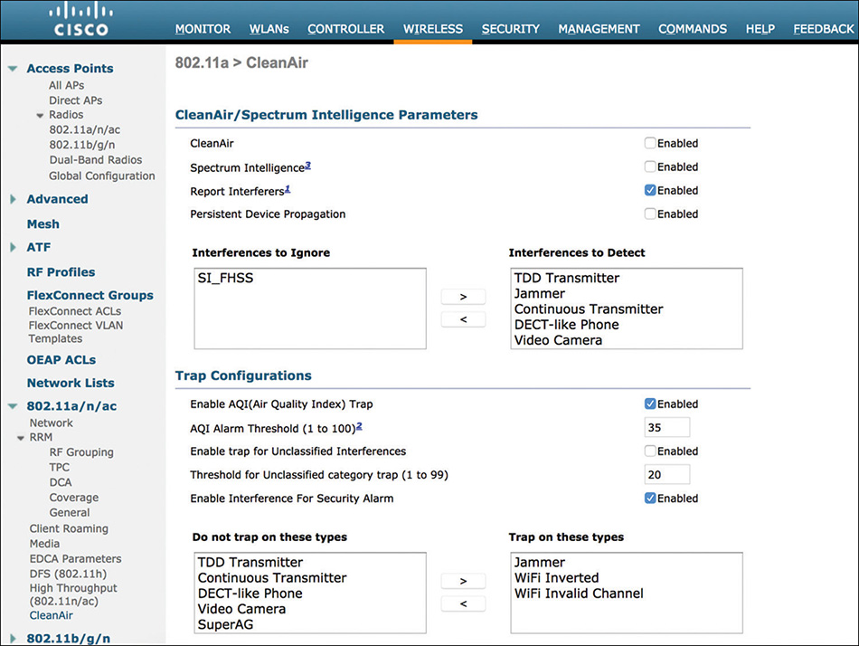
The CleanAir box enables CleanAir globally for that band. There is close to no impact when enabling CleanAir. You can then enable the reporting of interferers as well as persistent device propagation, which will make the CleanAir APs tell the non-CleanAir APs of the same WLC about persistent interferer so that they apply a bias in their DCA and try to avoid those persistent devices.
Below, you can choose which interferer type to detect or ignore. Be aware that BLE beacon detection does cause some packet loss on 2.4 GHz. All the other types have no impact on performance. CleanAir is a separate chipset from the Wi-Fi radio (so no impact there) but it still has to use the same antennas as the Wi-Fi chipset and therefore can listen to the medium only when the AP is not transmitting. This means that CleanAir is active only for the current channel on a client serving AP, but on all channels on monitor mode APs.
On the Monitor tab of the WLC web interface, you will find a CleanAir page that will list interferers by bands, as well as air quality report. Air quality is a metric evaluating the impact of non-Wi-Fi interferers to the current channel: 100 being the perfect clean channel and 0 the worst unusable one.
Transmit Power Control
The role of transmit power control (TPC) is to limit the transmit power of the APs to limit co-channel interference. The idea is to keep an optimal coverage and have a reasonable overlap between APs’ coverage cells, but not have too much overlap, which would harm channel reuse capabilities and could cause clients to stick to the AP when a closer AP would be a better choice. Like DCA, TPC runs on the RF leader at regular configurable intervals or on demand (freeze), or not at all. There exist two versions of the TPC algorithms that have slightly different objectives. Both algorithms work based on the Rx and Tx neighbors of the APs.
TPCv1 checks the third loudest Tx neighbor of an AP and will take actions if it is louder than the configured TPC threshold (−70dBm by default), along with a few other considerations. This setting should be configured identically on all the WLCs.
TPCv2 calculates the cell boundaries and optimizes the coverage so that the overlap is the minimum while still making sure there is no coverage hole. The formula is therefore much harder to track and verify manually for the administrator.
It is also possible to configure upper and lower limits—the minimum and maximum transmit power, as shown on Figure 4-47. These fields are in dBm, which requires you to translate the AP power level to actual dBm. The purpose is when the APs are mounted close to each other but far away from targeted clients (when the ceiling is very high, for example). In such a case, APs will hear each other loudly and will have a tendency to reduce their power, but since clients are far away below, this is a bad idea. Limiting the Tx power boundaries in those cases allows you to set safety guards when you know that having the power above or below a certain limit is an absolute no-go. It is interesting to know that power level 1 represents the maximum Tx power allowed for that channel in the configured country at a data rate of 6 Mbps (that is, without beam forming, for example.)
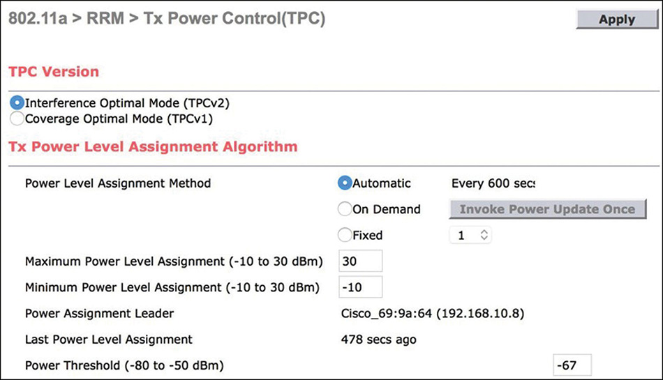
RF Profiles
RF profiles can be tied to AP groups and allow you to configure a number of RRM settings (as illustrated in Figure 4-48) that will override the global configuration just for the APs in the group where the RF profile is applied. It does not allow you to enable or disable major features (like DCA or TPC) per AP group, so the feature should be enabled globally, but a lot of settings can be overridden. A few examples are DCA channels, channel width, TPC thresholds, coverage hole detection settings, and profile threshold for traps. For best consistency, the RF profiles you plan to use should also exist on the RF leader (which is the one that will make the decisions in a lot of RRM-related cases). This means that the AP groups should also exist on the RF leader, even if the APs are not registered to it. To prevent any kind of mismatch where the settings you want are not actually applied to the specific APs you targeted, it’s best to push all these settings to all controllers at the same time, possibly with Prime Infrastructure.
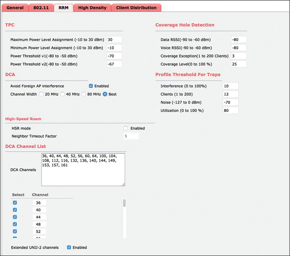
Data Rates
Wireless clients can send each frame at a different data rate. A data rate was originally something easier to remember and visualize than a modulation with error coding capabilities. In 802.11a, all data rates are based on OFDM modulations. However in 2.4 GHz, some rates are not based on OFDM (1 Mbps, 2 Mbps, 5.5 Mbps, and 11 Mbps) because they come from 802.11b, whereas 6 Mbps and 9 Mbps are OFDM based and are therefore restricted to 802.11g clients and later. By disabling certain data rates, we can decide to exclude certain client types (like 802.11b by removing all their modulations), but this is not the only purpose. Data rates are not only enabled or disabled, they can be supported (which basically means they are allowed and enabled) or mandatory (which means the associating clients must support them). You must configure at least one mandatory data rate because this is the data rate at which beacons will be sent to make sure all clients hear the beacon because they are all supposed to support that data rate. If several rates are defined as mandatory, the beacons will be sent at the lowest mandatory rate. Therefore, setting a higher data rate as mandatory has the effect of increasing the speed of beacons and pretty much all the management frames, which definitely speeds up the management overhead and increases medium efficiency. However, it also drastically reduces the effective cell size. The signal still propagates up to the same distance, but it’s not decodable as far away as before (a higher modulation becomes undecodable noise when SNR gets too low). Another particularity of mandatory data rates is that multicast is sent at the highest available mandatory rate (to combine efficiency as well as making sure all clients support it). The High Throughput page allows you to configure supported data rates for 802.11n and 802.11ac standards, as shown in Figure 4-49.
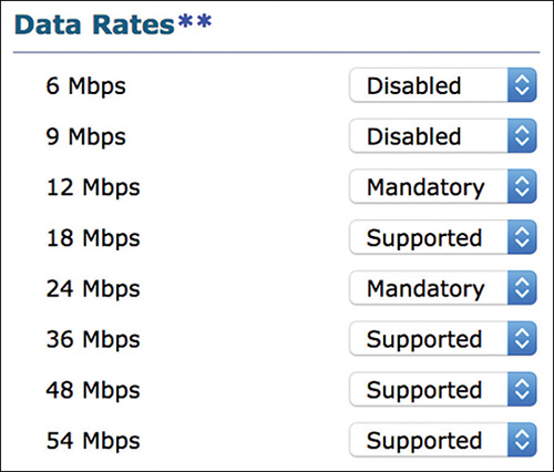
Apart from being called “MCS X” rather than using data rates in Mbps, those data rates cannot be mandatory and therefore have zero effect on management frames. Most people just leave all the 11n and 11ac rates enabled, but you could, for example, decide to remove support for the highest modulations (like MCS8 and MCS9) so that clients will not even try these risky modulations and will be less likely to lose frames trying them. This prevents data rate downshifting, but it is not common practice.
RX-SoP
The strange name RX-SoP stands for Receive (often shortened as Rx) Start of Packet. This feature also does something that might seem strange at first: reducing the receiver sensitivity of the radio. The idea is that in a dense environment, we know that there are many roaming candidates for the clients, but sometimes clients will stick to an access point for a very long time even if the signal is bad. Depending on the Rx-SoP threshold chosen (as illustrated in Figure 4-50), the AP will choose to ignore packets that come under the corresponding RSSI threshold (which is different on a per-band basis). In fact, it will not even decode them and will simply consider them as non-Wi-Fi energy.
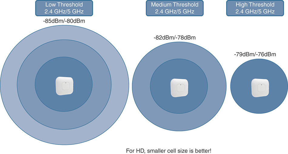
The effect is that the coverage cell size is reduced effectively on the Rx (from the AP perspective) side. Faraway clients will send frames that the AP will not acknowledge, and those clients will get the message and move to another AP. However, frames sent by the AP will still travel the same distance, but if you disable the lowest data rates on the AP, that will have a similar effect and send frames that will not be decodable by clients far away (if they can’t decode the beacon, it’s as if they don’t hear the AP anymore). RxSoP is configurable globally as well as in RF profiles.
AirTime Fairness
In an attempt to ensure that some less important SSIDs or client types do not abuse the overall bandwidth, many administrators have the reflex of configuring data rate limiting (also called bandwidth contract). The problem with bandwidth rate limiting is that it is defined in Mbps usually and does not take into account the amount of clients present (why restrict speed if there is no one else on the network?) or the usage made by other clients or SSIDs. The lack of efficiency is particularly in the upstream direction because the client already sent the frame over the air (the critical and slower part usually), and we would drop it on the AP or WLC because the client already sent “too much,” which preserves the WAN maybe but not the AP air time. Moreover, in wireless, a slow client using very low data rates (even if not transmitting huge files) is more annoying to other clients than a client sending a large file but at high data rates, meaning the transfer will be over quickly.
AirTime Fairness (ATF) focuses on limiting air time rather than specifying a given bandwidth. It is applied only in the downstream direction (from AP to client) because we cannot honestly control when and if clients can transmit. Each time the AP has to send traffic on a given WLAN, it will count the airtime consumed by data frames, and when the “bucket” is full, it can either defer the traffic to send (in a limited buffer) or drop it (which also happens if the buffer gets full). ATF can be disabled, or enabled in monitor mode (that is, it only counts statistics and does not defer/drop traffic) or in enforcement mode.
In the Wireless > ATF > Monitoring page (as shown on Figure 4-51), you can configure a specific AP, AP group, or the whole 2.4 GHz/5 GHz network to start monitoring ATF statistics.
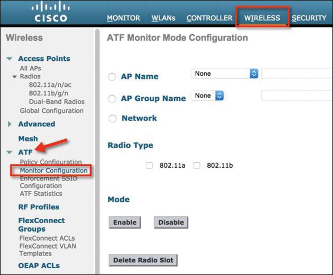
After statistics have been collected, you can consult them in the statistics page in the same menu, as shown in Figure 4-52.
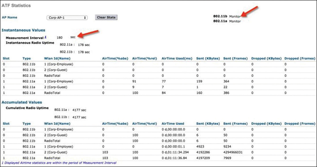
To enforce, you first need to create policies. An ATF policy is basically a weight (in percentage) or the air time you want to allow. You can then go to the Enforcement SSID Configuration page and apply these policies to specific WLANs on a per AP, per AP group, or whole network basis. The idea is to define a percentage of air time a WLAN can get over another. There is a strict mode, where the WLAN will be limited to the policy no matter what, and an optimized mode, where more air time will be given if the other WLANs are not using their share of air time. ATF guarantees air time for given WLANs regardless of the amount of clients connected. The Client Fair Sharing check box in the ATF policy page is an additional option that means, when enabled, all clients of that WLAN will be treated equally. Without that feature, if you configured the guest SSID to be limited to 20% of the air time, the whole guest SSID will be following that limit. But one guest may be downloading more traffic than other guests and starving them. Client fair sharing takes the configured maximum air time for the WLAN and divides it per client, making sure one client does not have priority over another one.
Configuring and Troubleshooting Mobility
Mobility is at the core of 802.11. Freedom of movement has been the reason why Wi-Fi adoption has steadily grown over the past decade. However, seamless roaming is still an issue, and you can expect that your troubleshooting skills will often be solicited for issues around mobility. In most cases, a deep understanding of RF will bring the solution. However, you should also be deeply familiar with the roaming mechanisms between APs and between WLCs, and understand the exchanges and the expected states. This section will provide these tools.
Layer 2 and Layer 3 Roaming
The Layer 2 versus Layer 3 concept comes from the early days of AireOS, when WLAN controllers were strictly switching (an SSID in a WLC could be associated to only one subnet and VLAN). With AAA override and multiple types of grouping possibilities within the same WLAN, the concept has evolved over the years. Fundamentally, the notion of roaming “layer” refers to the relationship between the VLAN and subnet to which the user belongs before the roam, and the VLAN and subnet to which the user belongs after the roam. If the VLAN and subnets are the same before and after, the roam is Layer 2. If they are different, the roam is Layer 3.
In the documentation, intra-WLC roam (that is, mobility between APs connected to the same WLC) is always described as Layer 2, because the user is expected to be sent to the same VLAN and subnet. However, with AP groups, Flexgroups, and multiple other types of configuration structures, a user may be sent to a different VLAN and subnet while roaming between APs on the same WLC and SSID. In this context, troubleshooting is usually related to understanding the new client context.
Intercontroller roaming presents a different challenge. WLCs need to know about each other so as to exchange mobility messages. If the WLAN to VLAN and subnet mapping are the same in the initial (the Anchor) WLC and the new (the Foreign) WLC, roaming is said to operate at Layer 2. The client database entry (also called client context) is moved from the anchor to the foreign WLC, then is deleted from the anchor, and traffic entirely flows through the foreign WLC. If the WLAN to VLAN and subnet mapping are different, the client entry is copied from the anchor to the foreign, stays on the anchor, and traffic flows from the client, through the foreign, then through the anchor and back, as shown in Figure 4-53.
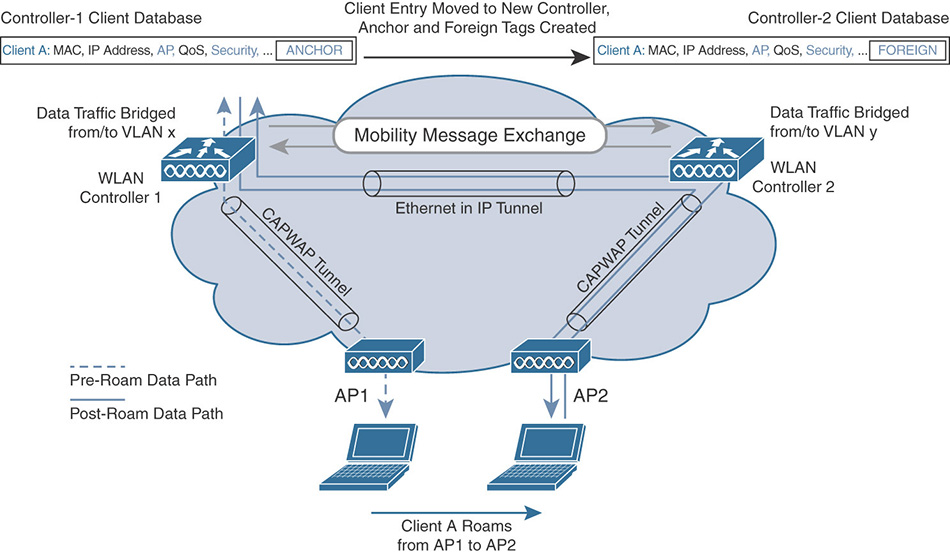
The key elements to ensure seamless intercontroller roaming are SSID configuration and WLC communication. On both WLCs, the SSID configuration must be identical on most points. When WLCs establish a communication channel to handle the roaming event, they compare the WLAN configuration. If the configuration is different, the WLCs will decide that the SSIDs are not the same (even if the SSID name is the same), and roaming may become a simple disassociation from the anchor WLC and new association to the new WLC. This event may be caused by the client inability to maintain the parameters from the previous WLC. As much as possible, you should ensure that parameters are the same for the SSID between WLCs.
This failure may come from the client rejecting parameters and disconnecting, or the WLC (rejecting client requests that do not match the WLAN). However, during the handoff event, the criteria used by the WLC to decide about a Layer 2 or Layer 3 roaming or disconnection are the SSID name and the VLAN. If they are the same, roaming is Layer 2. If the SSID is the same but the VLAN value is different, roaming is Layer 3. If SSID is different, the event is a disconnection followed by a new association.
Mobility Lists and Groups
A prerequisite to roaming is that WLCs know each other, so they can exchange information about clients. This prerequisite also means that the WLCs must be in the same mobility group, or mobility domain (the two terms mean the same thing). A mobility group is a set of controllers, identified by the same mobility group name, that defines the realm of seamless roaming for wireless clients. Controllers in the same mobility group can share the context and state of client devices, as well as their list of access points, so that they do not consider the access points of each other as rogue devices.
To make two controllers members of the same mobility group, you need two steps:
Input the same string in the Controller > General > Mobility Domain Name field, so that both controllers have the same mobility group/domain value (CLI config mobility group domain).
Inform each controller about the other in Controller > Mobility Management > Mobility group. Each controller needs to know the other controller’s management IP address and built-in MAC address (CLI config mobility group member add <MAC> <IP> <group>).
As a side effect of roaming, if you want roaming to occur smoothly, you should run the same code on both controllers (so that they speak the same language and understand the same options). Without this precaution, one WLC may share information about an option that the other WLC does not understand. You can verify the compatibility between WLC codes on this page:
However, compatibility does not mean that all features will be the same.
Additionally, you should also configure the same virtual gateway IP address (this address is used as a “virtual address” to make the client think that it connects to one big virtual controller instead of several physical controllers).
Mobility groups can contain up to 24 WLCs. However, a WLC can know about other WLCs with a different mobility group name configuration. As WLCs know one another, they are in each other’s mobility list. However, as their mobility group value is different, they are in different mobility groups. Figure 4-54 shows such an example, where a WLC in mobility group Mygroup is connected to two other WLCs, one in the same mobility group and one in another mobility group (none). Both 172.31.255.30 and 172.31.255.19 are in 172.31.255.40’s mobility list, but only 172.31.255.30 is also in 172.31.255.40’s mobility group.
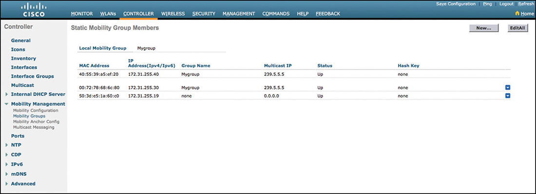
From a roaming standpoint, there is an important difference between mobility group and mobility list: Cisco Centralized Key Management (CCKM), 802.11r, and Proactive Key Caching (PKC) do NOT work across mobility groups. This means that if an STA roams to a controller that has a mobility group value different from that of the local WLC, a full reauthentication will be needed if the STA uses 802.11r (FT) or CCKM, or if your design needs to leverage PKC. The IP session will not be broken if roaming is Layer 2. In Layer 3 mode, a new IP address will be required. Therefore, this configuration has an important effect on roaming, especially if the STA uses a real-time application (VoIP or other).
Mobility Messaging
When an STA joins an SSID on an AP, the associated WLC tries to discover whether the client is roaming. For that purpose, the new (foreign) WLC checks whether the STA is known locally (entry in the WLC client database). If the STA is not known, the WLC sends a mobile announce message to all WLCs in its mobility list (same mobility group or not). The mobile announce includes the STA MAC address. A WLC that knows the client (prior, or anchor controller) responds with a mobile handoff message that passes the STA context to the new WLC. The WLCs use a mobility control tunnel to exchange this information, running on port UDP 16666. In the case of a Layer 3 roaming, the STA data will continue to flow through the WLCs using an EoIP tunnel. The choreography is displayed in Figure 4-55.
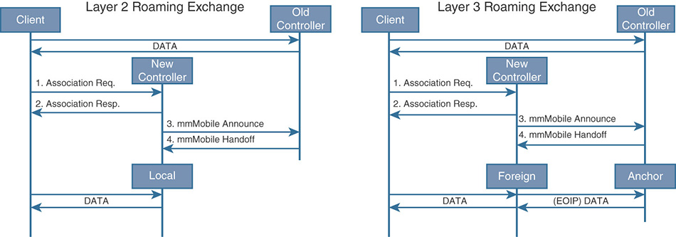
You should note that a new mobility mode, using CAPWAP encapsulation instead of EoIP, is available since AireOS code 7.3. This type of mobility creates a hierarchical structure (with mobility agents and mobility controllers). This mode is not functionally very different from the traditional (or flat) mode described here. In the context of the CCIE lab exam, this new mobility is not covered anymore, and in real life, the traditional mode is more common.
This mobile announce occurs for each new STA. By default, an individual message is sent to each other WLC. Such exchanges can create a lot of traffic on active networks. To simplify the flow, you can configure multicast messaging between WLCs from Controller > Mobility Management > Multicast messaging (CLI config mobility multicast enable family of commands). This configuration supposes that your wired network is also configured to support multicast communications. By default, multicast is not forwarded across subnets.
With multicast messaging, your WLC sends one mobile announce to the multicast address. The other WLCs have subscribed to the same multicast group and receive the message. The process creates fewer strains on the wired part of your network.
You can configure a different multicast address for each mobility group known by the WLC. In Figure 4-56, the WLC has two different multicast addresses configured, one for each mobility group (239.5.5.5 for the local Mygroup mobility group and 239.5.5.6 for the none mobility group).
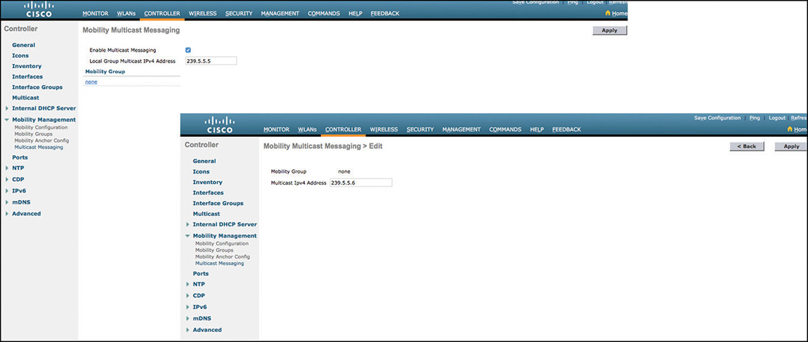
The multicast address can be the same for more than one (or all) mobility groups. The decision depends on your mobility design. For example, if your network has two mobility groups, and WLCs for each group are in different areas of your network, you may want to configure different multicast addresses. If WLCs are in the same area (same group of subnets), a single multicast address is likely sufficient to reach them all while avoiding duplicates.
All the WLCs in the same mobility group should be configured with the same mobility multicast settings. The address you configure is used to send mobile announce messages, but the WLC will also subscribe to the traffic sent to that address, so as to receive the mobile announce from the other WLCs.
Mobility Anchors
There are cases where you always want traffic to be sent to a specific WLC. A common scenario is guest networking, where a WLC is in the DMZ, and all client traffic for the guest SSID should be forwarded there, to avoid guest traffic to stay in the corporate network. To achieve this goal, you need to configure a mobility anchor information from the WLAN main page, for the target WLAN, as shown in Figure 4-57 (CLI config mobility group anchor family of commands).
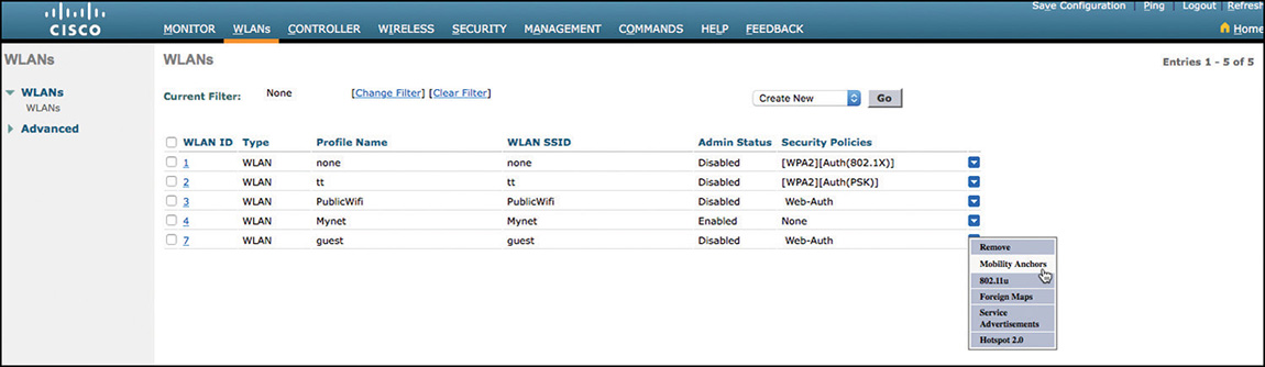
The DMZ (anchor) and the foreign controllers should be in each other’s mobility list. They should in most cases be in different mobility groups, because you do not expect roaming in this case (all traffic is terminated on the anchor, never on the foreign, and the anchor probably does not even manage APs).
The SSID should exist on all the WLCs (foreign and anchor). Here again, the SSID configuration should be the same on both ends. However, three parameters can be different: the PSK, if any (only the PSK on the foreign WLC matters), the RADIUS server, and the DHCP server for the SSID (only the DMZ configuration matters).
To configure such anchoring, in all the corporate WLCs where the guest SSID is configured, select the DMZ controller as the mobility anchor. In the DMZ controller, choose the local (DMZ) controller as the mobility anchor (itself). This second step is critical, to let the DMZ WLC know that it is supposed to terminate requests coming from the other WLCs. In the corporate WLCs, you can send the traffic to be terminated to more than one DMZ WLC. In that case, you can decide which DMZ WLC is primary (has the highest priority). The DMZ WLC with a lower priority will be selected if the DMZ with a higher priority stops responding.
After WLCs within the corporate network and anchor (DMZ) WLCs are connected, they will send keepalive messages, even when no client is connected. From the Controller > Mobility Management > Mobility Anchor Config, you can configure the periodicity of these keepalives (CLI config mobility group keepalive), along with the retry count (before deciding that the other side is not responding anymore) and the DSCP marking of these messages.
Troubleshooting Mobility
The most common issue affecting inter-WLC mobility (Layer 2 or Layer 3 roaming, and auto-anchoring) is a mismatch in configuration that causes the mobility tunnel to fail. The debug mobility handoff enable command (along with debug client <MAC> to filter the output to only the client of interest) will show everything you need to know. For example:
(Cisco Controller) >debug mobility handoff enable

*mmListen: Jun 07 10:00:21.405: 40:55:39:a5:ef:20 Adding mobile on
  Remote AP 00:00:00:00:00:00(0)
*mmListen: Jun 07 10:00:21.405: 40:55:39:a5:ef:20 mmAnchorExportRcv:,
  Mobility role is Unassoc
*mmListen: Jun 07 10:00:21.405: 40:55:39:a5:ef:20 mmAnchorExportRcv
  Ssid=webauth Security Policy=0x2050
*mmListen: Jun 07 10:00:21.405: 40:55:39:a5:ef:20 mmAnchorExportRcv:
  WLAN guest policy mismatch between controllers, WLAN guest not
  found, or WLAN disabled. Ignore ExportAnchor mobility msg. Delete
  client.

(Cisco Controller) >
In this case, the policy for guest is not found, which indicates that there is a policy mismatch. You should verify and carefully review the SSID configuration on each WLC.
When a client roams, mobility exchanges will flow, starting with the mobile announce and handoff messages, and when anchoring happens, to establish the tunnel for the first client (next clients will use the same tunnel). You should see the anchor and foreign IP addresses clearly. Show client summary should also display the anchor state. On the anchor, the AP name is the foreign WLC IP address.
Another, less common, issue is the mobility tunnel not coming up between WLCs. You should ensure that EoIP and UDP 16666 are allowed on the path, and also be aware that the tunnel may take a few minutes to come up. The control and data path come up successively. debug mobility peer-ip <IP> and debug mobility packet enable can help you observe the exchanges. In most cases, a mobility group string value, IP, or MAC address error is to blame. Observe carefully to catch the probable typo.
Wireless Client Roaming Optimization
Always keep this in mind: 802.11 Wi-Fi roaming is a client decision. The wireless client is the one that decides why to roam, when, how, and where to roam. In addition, this behavior is not the same for all wireless clients, because there are no specific 802.11 standard rules that must be followed for the roaming process, so each client vendor relies on multiple factors to trigger a roaming decision, as mentioned in Chapter 3, “Autonomous Deployments,” such as current AP beacon loss, current signal quality going down, availability of other APs around, shifting down to low data rate, packet retries and loss, channel utilization, current activity (on an active call or not, for example), and others. However, it is also important to clearly understand the many possible options and methods that exist to improve the wireless client roaming behavior. Some of the options available are merely WLAN infrastructure features; others rely on the client or require client support (some methods are based on a standard, others are not).
In this section we cover the most important and widely implemented options that you can manipulate in AireOS WLAN infrastructures to optimize the wireless clients’ roaming events.
Band Select
When wireless clients start an association or a roaming (reassociation) event, they scan for APs around, looking for the best connection quality, with preference to current SSID (or the SSID selected if it was initial association) or to known SSIDs, and sometimes preference to current radio bands. This client scanning in its most basic form is passive (by just hearing APs’ beacons in supported channels while scanning them, with each radio if dual-band client) and active (by proactively transmitting 802.11 probe requests on supported channels waiting for probe responses from APs).
802.11 beacons and probe responses from APs (along with the signal quality in which they are perceived) are the minimum information that 802.11 wireless clients use from that scanning activity to decide what AP to select when associating or reassociating.
The purpose of the Band Select or Band Selection feature in AireOS is to manipulate AP’s probe responses in an abnormal, out of the standard way, trying to influence the clients to select the AP in the 5 GHz band instead of the 2.4 GHz band (no need to discuss in this section of the book why the 5 GHz band, if available with similar or higher signal, is a better option than 2.4 GHz). This is why the feature is not based on a standard and doesn’t rely on the client “supporting” the feature. It is actually a WLAN infrastructure (WLC/AP) feature based on a specific algorithm performed to change the behavior of the 802.11 probe responses.
In summary, the way it works is that probe responses in the 2.4 GHz band are suppressed, while the ones in the 5 GHz band are transmitted normally by the APs in response to probe requests, hoping that the client will prefer the 5 GHz band in the absence of probe responses in the 2.4 GHz band. Nowadays, latest dual-band wireless clients normally prefer the 5 GHz band, but there are still many clients that sometimes prefer the 2.4 GHz connection, even when the availability of 5 GHz APs/BSSIDs is still a good option. Therefore, with this feature enabled at the WLAN/SSID level in the WLC with the command config wlan band-select allow enable wlan_ID, wireless clients will hopefully choose the 5 GHz band.
The specific behavior of the feature depends mainly on whether the client is dual-band and its RSSI (the client’s signal quality perceived by the AP, which can be checked at the AP CLI using the command show controllers d0 | begin RSSI for the 2.4 GHz and show controllers d1 | begin RSSI for the 5 GHz). There are also some variables that can be configured to modify the algorithm of this feature, with options available at a global level in the WLC (not per WLAN), as you can see in Example 4-3.
Example 4-3 Global config band-select ? Command Output
(WLC) >config band-select ?
client-mid-rssi Sets the client mid RSSI threshold.
client-rssi    Sets the client RSSI threshold.
cycle-count    Sets the Band Select probe cycle count.
cycle-threshold Sets the time threshold for a new scanning cycle.
expire         Sets the entry expire.
We will explain the options based on the possible scenarios, but first, it is important to understand that the APs built a list of the probing clients to recognize single-band and dual-band clients that already went through this “probe suppression,” but because this list needs to be limited and up to date, such clients will expire from this list (age out suppression) after the period of time values in the expire options of the command (configured in seconds). The following are the two scenarios for Band Select that can help you to understand the rest of the command options:
Client RSSI is higher than both Mid-RSSI and Acceptable Client-RSSI.
Dual-band clients: 2.4 GHz probe responses are not transmitted at any time for dual-band clients, whereas 5 GHz probe responses are transmitted for all 5 GHz probe requests received (as it should, per 802.11 standard).
Single-band (2.4 GHz) clients: 2.4 GHz probe responses are sent only after the probe suppression cycle-count; if the cycle-count value is 2, probe responses will be transmitted after this counter reaches 2. How does this counter increment? The cycle-count becomes 1 after the AP receives the first probe request from the client (first time coming client, or a client that was already aged out with the expire timer), and will increment with the next probe request from the client only if the time difference between the successive probe requests is greater than the cycle-threshold value (milliseconds).
Client RSSI lies between Mid-RSSI and Acceptable Client-RSSI.
All 2.4 GHz and 5 GHz probe requests are responded to appropriately without restrictions. This is similar to having Band Select disabled for the WLAN.
The command in Example 4-4 is used to confirm the values configured for this feature (the ones in the example are the recommended and also default values in AireOS 8.3).
Example 4-4 show band-select Command Output
(WLC) >show band-select
Band Select Probe Response....................... per WLAN enabling
   Cycle Count................................... 2 cycles
   Cycle Threshold............................... 200 milliseconds
   Age Out Suppression........................... 20 seconds
   Age Out Dual Band............................. 60 seconds
   Client RSSI................................... -80 dBm
   Client Mid RSSI............................... -60 dBm
APs will trigger Band Select for a client only when they have both 2.4 GHz and 5 GHz radios enabled, and with the WLAN/SSID working for the two bands. It is not recommended to use this feature if the 5 GHz band coverage is poor or simply smaller than the 2.4 GHz coverage, because in those scenarios there will be areas where the 2.4 GHz connection might be the only option for the client, and suppressing it is obviously not a good idea. You should not use this feature if the WLAN is used to support time-sensitive applications (voice, video, or other real-time services) because it can affect the real-time performance during roaming due to delays caused by the suppression.
Load Balancing
Formerly known as aggressive load balancing, this is another WLAN infrastructure proprietary feature that doesn’t require any type of client support or configuration; however, it relies on specific 802.11 frames with the expectation that the client will understand that it should make a better decision (look for another AP that is less busy). The main purpose of the feature is to prevent clients from associating or roaming to busy APs if there are other APs around the area that are not as busy, trying to forcefully balance (by denying (re)associations) the load of wireless clients in coverage areas where more than one AP is available for the client to associate or roam. The way the WLAN infrastructure achieves this purpose is different depending on the AP mode:
Local mode AP: When the wireless client sends the 802.11 Association Request to the AP it decided to associate or roam to, but the WLC considers that this AP is busier than another AP available for this client (based on the feature logic, which we cover later), the AP will reply with an 802.11 Association Response using status code 17, which basically indicates that the AP is busy, and literally denies the client’s association attempt to this specific AP, hoping that it will immediately reattempt the (re)association with another AP.
FlexConnect mode AP: When the APs are in FlexConnect mode, they handle some decisions locally, such as the 802.11 (re)association handshake, which happens at the AP level instead of sending requests up to the WLC and waiting for the responses, because this could cause, for example, severe failures due to possible latency (or drops) in the path between the FlexConnect AP and the WLC. Hence, FlexConnect APs initially send a (re)association response with status code 0 (success) to the client while sharing the association attempt with the WLC and waiting for it to calculate the load-balancing decision (this happens at the WLC level in order to consider the current load of all the APs that this client can hear during that attempt). After calculations, if the WLC considers that this client should be denied in that specific AP trying to balance the load to another AP, then an 802.11 deauthentication frame with reason 5 is sent to the client, again, hoping that the client will attempt its next (re)association with a less loaded AP.
The load balancing algorithm denies clients, in any of the two ways explained previously, if it considers that an AP is busy. You can manipulate why an AP is considered busy based on two modes:
Client count: With the command config load-balancing window <client_count>, you configure the load-balancing “window size,” which is used to derive the actual threshold that determines, in each association attempt, whether an AP is busy due to client load when compared with other APs available for the client to also associate/roam. The amount of clients in the less loaded AP available for that client is the base of the equation, and the window value is the ratio with the threshold (APs with more clients than the threshold are considered busy). For example, if the config load-balancing window value configured is 5, and a client is trying to associate to AP1 (currently with 16 clients), but AP2 (with 13 clients) and AP3 (with 10 clients) are also available for that client, the less loaded AP available is AP3. Hence, with base client-count from AP3 as 10 + window 5, the threshold is 15. Based on this threshold, AP1 is busy, so the association is denied, expecting the client to make a better decision trying to associate to AP3 or at least AP2, because these APs are not considered busy in this area (at least not busy based on client count).
AP Uplink usage: When this mode is used, an AP is considered busy if the uplink interface of an AP is reporting utilization (in percentage) equal or higher than the one configured with the command config load-balancing uplink-threshold <traffic threshold>. The default value of the threshold is 50, so if the utilization of an AP uplink interface is 50% or higher than the interface’s capacity, and a client tries to associate with this AP, the association will be denied.
The desired load balancing mode is applied at the WLAN level using the command config wlan load-balance mode {client-count | uplink-usage} <wlan-id>.
This load-balancing method definitely affects roaming behavior, and that’s why we are covering the feature in this section of the book. Imagine a client trying to roam to a busy AP, where the reassociation is always denied, and the client is unfortunately not smart enough to attempt an association with a less loaded available AP, so it keeps trying and failing at a level that completely disrupts the roaming. When such persistent devices (or devices that can’t process appropriately responses with status code 17) are critical clients in your WLAN, or there are critical mobile devices using real-time services, it is not recommended to use this feature (disable it at the WLAN where those clients connect).
For very persistent devices, (re)association still needs to happen at some point, even if they are not critical clients. Hence, you can configure the maximum denial count with the command config load-balancing denial <denial_count>. With the default value of 3, the client experiences three association failures when trying to connect to a busy AP, but the next association attempt will be allowed.
Optimized Roaming
This is another Cisco proprietary feature that doesn’t require anything at the client side, but simple configuration at the WLC level. It is a wireless LAN controller global setting that can be applied per band (not per WLAN), and affects all types of clients as long as they meet the criteria to get optimized roaming applied.
This feature is similar to the load balancing feature, but their main difference is that load balancing affects client (re)association based on current AP load of clients, whereas optimized roaming affects client (re)association based on the client’s signal quality (RSSI, but data rate can optionally be considered). Another important difference is that the optimized roaming intention is to affect mainly wireless clients that have the “sticky” behavior of staying connected with current AP, even when the signal quality with that AP is going bad and other better APs are available (which is bad not only for this specific client but for the entire channel, because a client with bad performance, collisions, retransmissions, low data-rates, and so on also affects the performance of all other clients/APs using that channel).
How does that happen? How does optimized roaming affect client (re)association when a client’s signal quality is considered poor? There are two ways to achieve this:
Disassociations: In this scenario, the client is already associated; it is actually passing traffic and not trying to roam even when it should (due to current signal quality). Hence, WLC forces the client to roam to a better AP by proactively sending an 802.11 Deauthentication frame with reason code 7, such as the one shown in the packet capture of Figure 4-58.
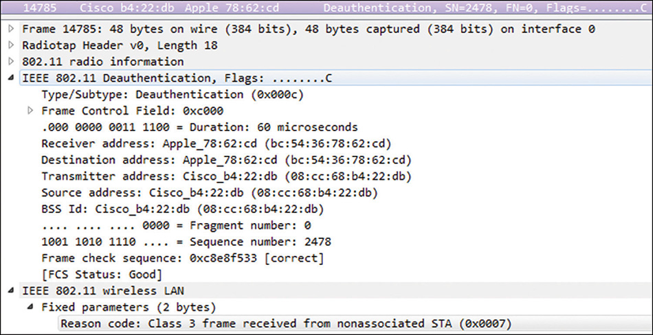
Figure 4-58 Deauthentication Frame Rejections: When attempting a new connection, during brand new association or roaming (reassociation) events, if the client tries to (re)associate to an AP with poor RSSI perceived by the AP, its association will be rejected with an 802.11 association response with status code 34, such as the one of the packet capture in Figure 4-59. This is exactly what will happen if the client tries to rejoin the same AP after getting proactively removed by the AP, as explained in the previous scenario (“Disassociations”). In fact, this type of association rejection will continue if the client keeps trying to rejoin the same AP, unless the client’s RSSI increases (per AP perception) 6dBm or more above the RSSI threshold.
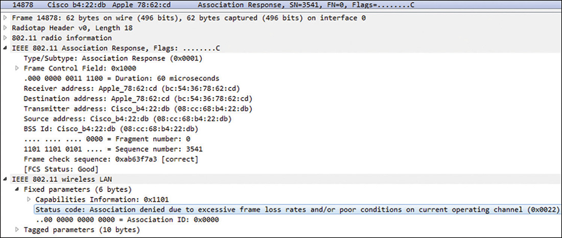
Figure 4-59 Association Response Rejecting Client
The optimized roaming algorithm disassociates or rejects the client as previously explained (another big difference with the load balancing feature, which only rejects; it doesn’t proactively disassociate clients already connected), triggered by the following conditions that you can configure:
Data RSSI value: This is the threshold that defines the RSSI limit; the client’s frames received at or below this RSSI value are considered of “bad signal quality.” Therefore, the client is applicable for optimized roaming. This threshold, as well as the next two thresholds to be explained, are used from the RRM feature known as Coverage Hole Detection (CHD), which already monitors clients for similar purpose. Hence, this threshold is configured under the coverage settings, with this data RSSI value configurable using the command config advanced 802.11<a/b> coverage data rssi-threshold <dBm>. This is considered for both disassociations (we explain later in this section how this applies to disassociations, because it relies on other values we are about to explain) and rejections (if a client tries to (re)associate with an RSSI at or below this threshold, it will be rejected).
Coverage Exception Level Percentage: Another CHD threshold, this is used by optimized roaming in disassociations to define the maximum percentage of data packets that can be received below the data RSSI value from an associated client. If this percentage is exceeded, the flag is raised for this threshold to trigger client disassociation by optimized roaming. This can be configured with the CHD command config advanced 802.11<a/b> coverage data fail-percentage <percent>.
Number of Data Packets Received: This is the minimum number of packets that must be received from the client (at any RSSI level, good or bad) to trigger client disassociation if previous conditions are met. This is also a CHD threshold, and the command to configure this value is config advanced 802.11<a/b> coverage packet-count <num-packets>.
Roaming Data-Rate Threshold: This one is optional and is disabled by default. When used, optimized roaming will apply disassociations only to clients connected at this data rate or lower. It is a good option if low or legacy rates are enabled, and some sticky clients stay connected at those low data rates far away from the AP. When disabled, optimized roaming applies to all clients meeting the criteria to be disassociated regardless of its data rate. This can be configured with the optimized-roaming command config advanced 802.11<a/b> optimized-roaming datarate <mbps>.
Optimized Roaming Interval: This is the time interval at which each AP reports the client statistics to WLC so it can calculate with the optimized roaming algorithm (using previously explained thresholds) if a client disassociation must be triggered or not. This is also configurable with an optimized-roaming command config advanced 802.11<a/b> optimized-roaming interval <seconds>.
Let’s use the example with the default values to better explain when exactly an optimized roaming disassociation will be triggered:
If optimized roaming is enabled and more than 25% (coverage data fail-percentage) of at least 50 packets (coverage packet-count) in a fixed 5 second period were received at −80dBm of RSSI or lower (coverage data rssi-threshold) from a client already associated, the AP will disassociate the client when the reporting interval of 90 seconds expires (optimized-roaming interval).
Note
As previously explained, optimized roaming is a global feature that doesn’t require activation or configuration at the WLAN level. However, because this feature relies on CHD parameters as previously explained, per-WLAN coverage hole detection must be enabled (config wlan chd <WLAN id> enable) on all WLANs that participate in optimized roaming.
As best practice, this feature is not recommended nowadays, mainly because it is too aggressive and could cause a lot of unexpected disconnections specifically in areas with poor coverage. So if you have a very good RF design with full coverage and still notice some specific devices acting as “sticky clients” with poor roaming behavior, you could enable and test this feature to check if it helps; otherwise, you had better keep this disabled and rely on standard methods such as 802.11k and 802.11v to suggest clients looking for a better AP.
802.11k and 802.11v
These are two IEEE 802.11 standard amendments that help to optimize client roaming. They are implemented by AireOS, which has them enabled by default when creating a WLAN/SSID, so wireless clients connecting to such a WLAN and officially supporting these standards will take advantage of their benefits. Using 802.11k and 802.11v is a recommended best practice and is suggested instead of proprietary methods like the load balancing and optimized roaming explained before, mainly as AireOS implements 11k and 11v with similar behaviors to those other features.
The way these two methods are implemented in AireOS is explained deeper in Chapter 7, “WLAN Media and Application Services,” so we are not covering all the details in this chapter; we just wanted to mention both in this section so it is clear to you that these are two very important methods to optimize client roaming decisions, specifically by suggesting better APs. Refer to Chapter 7 for more details, and for now, we will share a summary of how they work, mainly when compared to the methods already explained in this section.
As explained earlier, wireless clients spend some time and effort (including battery usage, for example) scanning for the best AP to (re)associate, based on active and passive scanning. This scanning and AP selection can be greatly improved if the client is suggested with specific APs (and their channels) as its best options to roam to, not only suggesting the best next option but also reducing the time-effort it takes for a client to make this decision while scanning. This improves a lot the performance during the roaming process for mobile devices, mainly with real-time applications; for example, instead of scanning all channels looking for the best option to roam to (remember that, while scanning, the client is perhaps on a live voice call moving away from its current AP cell at the speed of the user walking, and while this is happening, the signal quality of the current AP connection is getting worse, so call quality is probably getting affected), the client might only scan the three channels of the three specific APs suggested by the WLC.
The main purpose of these two standard methods in optimizing client roaming decisions is to suggest the client with the best candidates of APs where it could roam to when necessary, so the client can finally make a smarter and more efficient decision.
This is achieved with 802.11k by having the client proactively sending a neighbor report request to its current AP, and the AP replying back with a neighbor report response suggesting the best APs (a list of APs that is built by a complex algorithm at the WLC that can consider multiple factors and technologies, such as RRM neighbor information, signal between APs in the area, current AP location, floor information from Prime Infrastructure, and roaming history). After that exchange, the 802.11k client will look for the best AP from that list when it is time to roam.
Note
AireOS implements an optional variant known as Assisted Roaming for Non-802.11k Clients or Assisted Roaming Prediction Optimization, which is the option for clients that don’t support the standard 802.11k. This one is explained in Chapter 7.
In the other hand, the 802.11v amendment actually covers multiple features, one of which is specific to this method of suggesting APs to the client for smart roaming, and is known as 802.11v BSS Transition Management. AireOS implements 802.11v BSS Transition in four scenarios:
Solicited Request: The wireless client considers that it might roam soon, so it sends an 802.11v BSS Transition Management Query to its current AP, asking for a list of recommended neighbor APs to roam to (this query from the client has a reason code, such as reason 16, which means “due to Low RSSI”; other reason codes can be found in the 802.11 standard). In this case, the AP will reply back with a BSS Transition Management Request, sharing with the client the AP candidate(s) list.
Unsolicited Load Balance Request: If this 802.11v BSS Transition feature is enabled at the WLAN along with the load balancing feature, the AP will proactively transmit a BSS Transition Management Request to clients (suggesting less loaded APs) when the load criteria is met per load balancing (as explained earlier in this section).
Unsolicited Optimized Roaming Request: If this 802.11v BSS Transition feature is enabled at the WLAN and Optimized Roaming is also enabled, the AP no longer disassociates a client when optimized roaming is triggered (as explained previously when this topic was covered); instead, it will proactively transmit a BSS Transition Management Request to the client (suggesting APs with better RSSI).
Unsolicited Request by FRA AP with Dual 5GHz: APs that support Flexible Radio Assignment (FRA) have the opportunity to have two radio interfaces working in the 5 GHz band, one acting as micro cell and another as macro cell. If a wireless client associates to a FRA AP in this dual 5 GHz condition but joins the less ideal radio (that is, joins the macro cell when the micro cell is more optimal), the AP will proactively transmit a BSS Transition Management Request to the client suggesting the best radio (micro cell in this case).
As you can see, in all those scenarios the AP suggests to the client the best AP(s) it could roam to, but doesn’t disconnect the client; it is just a suggestion. However, 802.11v has the option to disassociate the client if it doesn’t move to a suggested AP after a period of time (only triggered if Disassociation Imminent is enabled; this option is further explained in Chapter 7).
Fast-Secure Roaming
802.11 wireless roaming events happen every time a wireless client moves from one AP to another AP, and every time such roaming happens, the wireless client needs to perform full new association and authentication with the WLAN infrastructure. The new association is actually a reassociation event (an exchange with the AP/WLC of reassociation request and reassociation response frames), and if the SSID is configured with WPA/WPA2 security, the WPA level authentication needs to happen again, as well as the WPA 4-way handshake required to derive new encryption keys (so encryption can happen with the new AP).
You can imagine the overload of authentication events happening in a secure mobile environment where wireless clients are constantly roaming (with a high amount of hits in the RADIUS server). In addition, there is something very critical happening while roaming: a period of time in which the wireless client cannot pass any traffic (data frames) at all. This is because it needs to go again through that mentioned process, as soon as it sends the reassociation request to the selected AP it is roaming to, before it can transmit or receive again any other data frame. It reassociates, then performs EAP authentication again with the RADIUS server, and finally completes the WPA 4-way handshake to derive new keys. Figure 4-60 demonstrates all the frames exchanged between the client and AP/WLC on a roaming event with WPA2/EAP authentication, before the client can continue passing data frames.
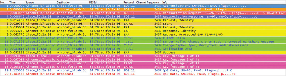
As you can see in Figure 4-60, the first data frame after the roaming event is frame number 19, and the amount of authentication frames during the EAP exchange could be higher depending on the EAP method and its settings. The fact is that several frames are required before the client can continue passing traffic, and this takes some time, which could be longer if there are big delays between AP and WLC, for example, and/or WLC and RADIUS server, or drops and retransmissions, or server not responding, and many other variables. The behavior just explained is normal and the way this WPA2/EAP security works; wireless clients must be “validated” again when moving to a new AP, and new encryption keys are required for security reasons. However, this can heavily impact the wireless user experience during roaming, mainly if running a sensitive application/service at the mobile device where timeouts can happen or traffic could be lost (for example, some audio missing during a voice call).
Fast-Secure roaming methods were invented to accelerate this normal process explained and shown in Figure 4-60. When a wireless client and AP/WLC apply a supported Fast-Secure roaming method, a secure roaming (with WPA2/EAP, for example) can be faster, using caching techniques to avoid a new EAP authentication handshake against a RADIUS server (hence also reducing server and network load), and sometimes even avoid the WPA 4-way handshake (while still deriving new encryption keys).
This topic is one of the roaming optimization features that require support in both the client side and the AP/WLC side. There are multiple Fast-Secure roaming methods available, and the Cisco WLAN infrastructure (AP/WLC) supports most of them, but most wireless clients support only one method (and some clients don’t even support one, so you need to confirm what your client devices support if you are trying to implement or troubleshoot Fast-Secure roaming). Some of the methods are not really a standard (so few devices support it), some are proprietary (like CCKM from Cisco), and there is one official standard method defined by the 802.11r amendment that looks for massive adoption (officially named Fast BSS Transition and known as FT or just 802.11r).
We are not covering all the Fast-Secure roaming methods supported by AireOS, but just briefly the two methods widely used in Cisco WLAN infrastructures (and that you must fully understand for the CCIE exam): CCKM and 802.11r/FT.
Note
There is a complete Cisco article that covers in depth all of the Fast-Secure roaming methods; it explains the working details and variants of each method, pros and cons, differences, and more. It demonstrates with wireless packet captures and WLC debugs the flow and handshake for every single method, explaining the meaning of the debugs and important frames/fields found in the wireless captures, to help you not only implementing a Fast-Secure roaming method when applicable, but to also understand and troubleshoot deeply any roaming or Fast-Secure roaming event.
We highly recommend that you study this article to get more details about this topic and mainly the methods covered in this book and the exam. You can find it at Cisco.com with the name “802.11 WLAN Roaming and Fast-Secure Roaming on CUWN,” and the following is its current URL:
CCKM
Cisco developed Cisco Centralized Key Management (CCKM) as the first Fast-Secure roaming method that could avoid EAP authentication and key management handshake during roaming events on an 802.11 WLAN using security with 802.1X. Only Cisco wireless clients (such as the IOS Autonomous WGBs and older Cisco VoIP phones) and some third-party clients that are Cisco Compatible Extensions (CCX)-compatible support CCKM.
CCKM works on top of an 802.1X/EAP authentication method to cache the secured session at the client and a centralized WLAN device (in this case, the AireOS WLC) during the client’s first association/authentication. With this caching technique, the client avoids EAP authentication when it reassociates (roams) to another AP managed by that centralized device, because the session is still valid (cached).
In addition, remember that when EAP authentication is used in Wi-Fi, some type of encryption is required to secure the data frames of the authenticated session, so CCKM also deals with the encryption by performing special key-management techniques that help to derive encryption keys for all known encryption types (WEP, TKIP, and AES-CCMP). That means that you configure CCKM to use it when EAP authentication is implemented with WEP encryption, with WPA/TKIP, or with WPA2/AES. Today, most wireless clients that still use CCKM support it with WPA2/AES, which is the most secure, and is configured (using the GUI) in the AireOS WLC WLANs/SSIDs, as shown in Figure 4-61.
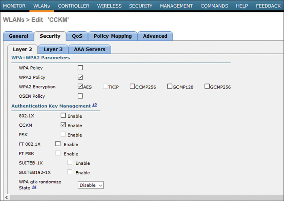
With that WLAN configuration, only wireless clients that support CCKM will be able to associate to this SSID. If you want to take advantage of CCKM for wireless clients that support it, but still allow associations of wireless clients that don’t support CCKM (but still support WPA2/AES with the EAP method used), then the only extra configuration that you need to add is to enable 802.1X (mark its check box, so the configuration will be 802.1X + CCKM).
Some wireless clients do not need any special WLAN configuration for this and will negotiate CCKM after they notice that the WLAN infrastructure (WLC/AP) advertises CCKM support during association. Other clients will require manual configuration, but it is normally as simple as selecting the combination of CCKM+EAP+WPA2/AES. Chapter 3 covers the configuration of a Cisco IOS Autonomous WGB for CCKM with WPA2/AES Enterprise.
Avoiding EAP (and even the handshake to derive new encryption keys) in each roaming event is achieved by using the already cached information and negotiating the rest with CCKM techniques during the reassociation exchange (reassociation request from the client and reassociation response from the AP). Figure 4-62 shows the frames exchanged between client and AP/WLC during a roaming event with CCKM.

As you can see in Figure 4-62, after the wireless client and AP/WLC exchange those initial four 802.11 management frames, 802.11 data frames can continue in the network for this client. This is very fast because those four management frames are always required to join an AP and happen quickly (Open System Authentication from the client, another back from the AP, then (re)association request, and (re)association response), so the client is immediately passing data frames without much delay as soon as it moves to the new AP.
802.11r/FT
This is the actual 802.11 standard amendment that provides the guidelines to perform Fast BSS Transitions (fast roaming) when a WLAN is using security. Enterprise WLANs had implemented a few other Fast-Secure roaming methods (such as CCKM) before FT was officially ratified in 2008, so it had a slow adoption, but it is nowadays the embraced method for mobile devices, and the recommended one (unless CCKM is required for clients that do not support 802.11r).
802.11r performs a job similar to CCKM, because it avoids both the EAP authentication and the key-management handshakes, but it works only for WPA2/AES because this standard is for 802.11i RSN (Robust Security Networks). Because of the way its key caching techniques and key hierarchies are implemented (out of the scope of this book), 802.11r also takes advantage of Fast-Secure roaming for WPA2-Personal (PSK) and not just WPA2-Enterprise (EAP), making WPA2-Personal roaming even faster by avoiding the WPA2 4-Way handshake.
It also works by caching the client session and seed key material from initial association/authentication with the WLAN, at both the client and AP/WLC levels. The WLAN infrastructure advertises FT support; hence, client and AP/WLC negotiate FT during the initial 802.11 Association Request and Response exchange. Once associated (and after initial EAP authentication with RADIUS if using 802.1X), the client and AP/WLC perform key-management during the initial FT 4-way handshake (which is similar to the WPA2 4-way handshake, with four EAPOL messages exchanged between client and AP/WLC; just slightly different in content due to specifics in the FT key hierarchy). Figure 4-63 shows the beacon from an AP advertising FT support.
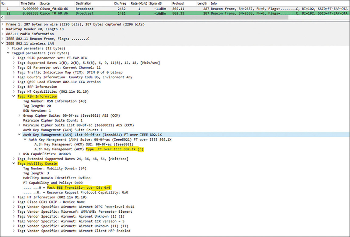
As you can see from the highlighted sections of the beacon frame, this AP is advertising required support for FT within the RSN Information Element; specifically saying that the Authentication Key Management (AKM) type supported requires FT with 802.1X (doing an EAP method). There is also a Mobility Domain Information Element with further details and capabilities used by FT in this BSS (as 802.11r supports multiple variants).
In summary, the following are the FT variants supported by Cisco WLCs, and the way you can configure them using CLI commands:
First, it is configured at the WLAN level, and you can enable it, disable it, or leave it in Adaptive mode (special option for Apple iOS clients, which is further explained in Chapter 7), with the following command: config wlan security ft {adaptive | enable | disable} wlan-id.
During a roaming event, wireless clients can perform Fast BSS Transitions in two ways: the most used and recommended method is known as “Over-the-Air.” With this method, the client starts FT roaming against the target AP it is roaming to, by exchanging with this new AP the typical 802.11 Open System Authentication frames but that this time contain FT information used to perform the Fast-Secure roaming (based on initial FT association exchange and cached session that happened when the client first joined the WLAN).
The other method is to perform FT “Over-the-DS” (Distribution System). In this case, the client sends an FT Action Request frame to its currently associated AP containing FT information (which has the target AP it is roaming to), so its current AP can send this request to the target AP over the distribution system (in this case, through the WLC), which sends back to the client an FT action response frame. After that exchange (which achieves basically the same purpose as the Open System Authentication exchanged when doing Over-the-Air), the client can initiate the Fast-Secure roaming with the target AP by exchanging reassociation frames (now over the air, as usual). Only one of the two methods is allowed per SSID, and they are configured with the command config wlan security ft over-the-ds {enable | disable} wlan-id. When using the disable version of the command, you configure the method Over-the-Air.
FT for SSIDs with WPA2 Enterprise (with 802.1X/EAP), configured with the command config wlan security wpa akm ft 802.1X enable wlan-id.
FT for an SSID doing WPA2 Personal (with PSK). In this case the command is config wlan security wpa akm ft psk enable wlan-id.
FT can also be optional for the clients connecting to the SSID, also known as “mixed mode” (or “hybrid mode”), where clients are supposed to connect doing the WPA2 method configured, even if they don’t support 802.11r. Clients that support 802.11r will negotiate it during the association, but clients that do not support it are supposed to do regular WPA2/EAP. Unfortunately, some old clients don’t behave as expected and might fail to associate to an SSID configured in this “mixed mode” advertising both methods (this is why it is not recommended to use mixed mode, and the reason why FT in adaptive mode was developed with Apple). For example, in this mixed mode, regular 802.1X/EAP is advertised and allowed (configured in the SSID with the command config wlan security wpa akm 802.1x enable wlan-id), while 802.1X/EAP with FT is also advertised and allowed (configured with the command previously explained, config wlan security wpa akm ft 802.1X enable wlan-id). The same can be done for PSK.
Figure 4-64 is a wireless packet capture example of a Fast BSS Transition happening Over-the-Air for an RSN association with WPA2 Enterprise (802.1X/EAP) in an SSID that allows only clients that support FT in this mode (so no mixed mode configured).
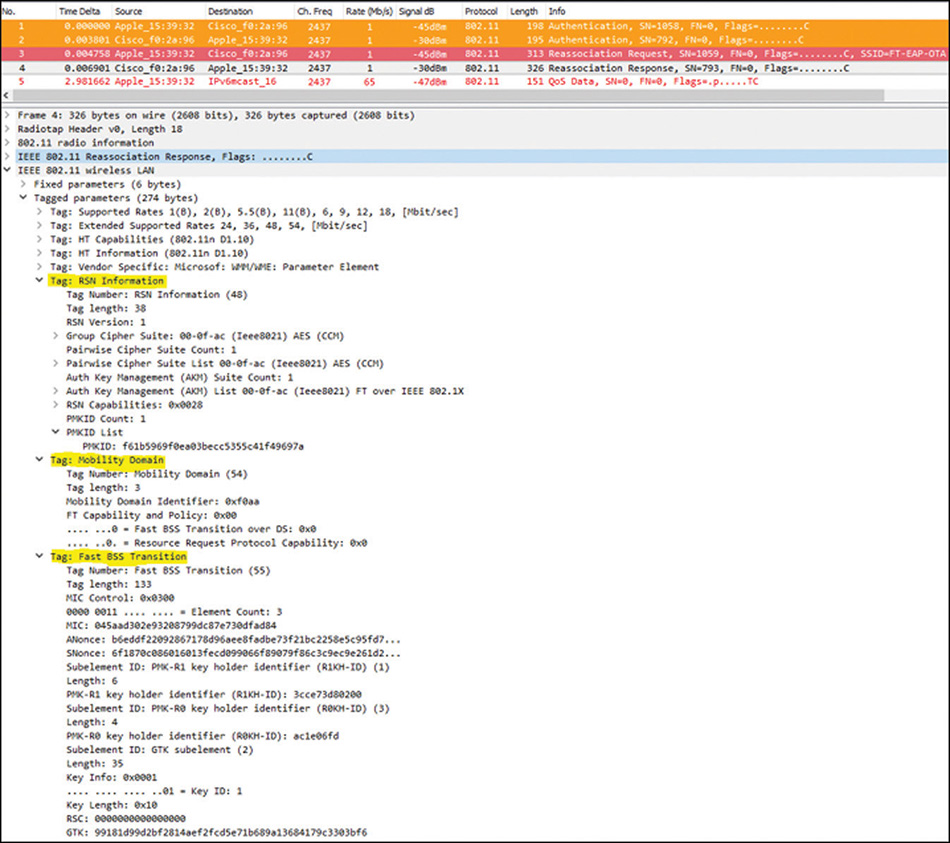
As you can see from Figure 4-64, just like in CCKM, only the four (always required) initial management authentication/reassociation frames are exchanged with the AP before the client can continue passing data frames, avoiding both the EAP handshake and also the key-management handshake. FT Authentication and AKM happen during the exchange of those four frames, because all those four frames contain FT material that help to validate the cached FT session and derive the new encryption keys. In fact, the first two Authentication frames are not regular Open System Authentication frames but Fast BSS Transition Authentication frames, where the FT handshake starts.
In Figure 4-64, the Reassociation Response frame from the AP (which confirms that the Fast BSS Transition was successful and finishes the FT handshake) is selected from the packets captured to show the highlighted three Information Elements (IE), which are the ones that contain the FT details exchanged within those four management frames during the roaming event. The first two IE are the ones explained earlier (advertising the FT mobility domain details and capabilities, as well as the support for Over-the-Air with 801.X), and the third is the Fast BSS Transition IE, which contains most of the information of this client’s FT session and the key material used to derive the new encryption keys.
Summary
This chapter is likely one of the longer and more critical for your exam preparation. Because the WLC is at the core of the wireless expert daily activity, you are expected to know each of its functions in detail. You should understand and be able to explain in simple terms each option present in the WLC GUI and each CLI command. You should also be aware that some advanced functions are not available in the GUI. This limitation does not mean that you should ignore the GUI and focus solely on the CLI (although this is definitely a possible path). However, you should be comfortable enough with the CLI to “survive” the requirement to configure a function without the assistance of the GUI.
Additionally, keep in mind that experts are not commonly called to perform simple or common configuration tasks. In most cases, experts are needed to realize uncommon combinations or troubleshoot issues that less-skilled professionals could not solve. These requirements mean that you should be able to use debug commands to observe the effect of your configurations. You should know what messages are expected when your configuration is activated, and what messages appear when things go wrong. A good way to prepare is to voluntarily misconfigure items (the WLC or the client side) and observe the resulting debug messages. Investing the time needed to acquire this understanding will save you time later. In most troubleshooting scenarios, whether in the lab or in real life, pressure is high to fix the issue as fast as possible, and familiarity with the debug outputs is often a key to troubleshooting efficiency.