
Chapter 6
Prime Infrastructure and MSE/CMX
Management tools are becoming more and more important for installing and maintaining any type of network. Although you may get personal satisfaction from configuring SSIDs, RF parameters, and debugging logs through convoluted AP and WLC command lines, a proper management system can perform all those tasks faster, and at a large scale. On top of standard configuration tasks, management tools also have the advantage of centralizing data from different sources and providing common features to troubleshoot, alert, and log information from heterogeneous systems.
Listing every feature of the Cisco Prime Infrastructure management system would probably require a book of its own. Nevertheless, this chapter should provide you with all the information about its major capabilities, as well as its complementary solution for specific WLAN services, like location and analytics, which is Cisco Connected Mobile Experiences (CMX).
Managing the Management
Accessing the graphical user interface (GUI) is the first task you need to complete to start using Cisco Prime Infrastructure, and differentiated access for administrator groups and privilege levels assignment are among the first requirements of a management tool. A more common definition for this type of feature also goes under the name of multitenancy. As you will see in the next paragraphs, Cisco Prime Infrastructure can provide some kind of user control capabilities through authentication and authorization services, as well as separated access to network device groups and sites through the notion of virtual domains, although not quite full multitenancy options.
Authentication and authorization define the menus and tasks that an administrator can access, and a virtual domain defines the group of network devices on which the administrator can run those tasks.
You may have already guessed that the most basic form of administrative authentication and authorization is through local accounts. A local account is simply a sequence of username and a password, stored in Prime Infrastructure’s local database, which you can map to a group. A group, or role, defines the privileges of an administrator account, hence determining menus that an administrator with that specific role can access. In Prime Infrastructure you can find the full list of predefined groups under Administration > Users > Users, Roles & AAA > User Groups, which is shown in Figure 6-1.
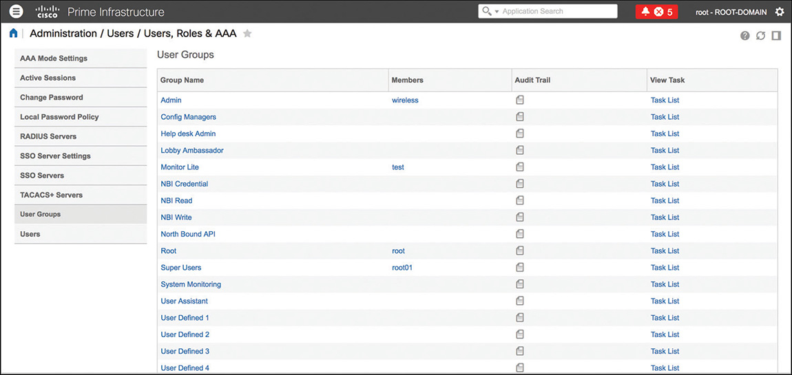
On top of predefined groups with their preconfigured tasks privileges, you can also customize up to four user-defined groups.
Cisco Prime Infrastructure supports authentication of administrator accounts through external RADIUS or TACACS+ servers. The goal of such servers is not just to validate logins and passwords against external databases but also to assign groups and privilege levels for accessing specific tasks. An authentication server achieves this by including additional attributes in the RADIUS and TACACS+ response. It is those attributes that contain the values that tell Prime Infrastructure to what group the authenticated user belongs, as well as the tasks that the user has access to for TACACS+.
All this may sound similar to what you can implement with authorization commands and TACACS+ on switches, for example. However, menus and features that you access through the GUI in Prime Infrastructure do not have their equivalents through the command line. For that reason, we cannot literally refer to “command” authorization on Prime Infrastructure, but rather to menus and tasks authorization.
When authenticating administrators via RADIUS, Prime Infrastructure uses the value [1] Login in the RADIUS attribute [6] Service-Type. This attribute allows you to identify RADIUS requests from Prime Infrastructure and to configure your authentication policies on the RADIUS server accordingly.
The attribute used to assign a group in the RADIUS response is the Cisco Attribute Value Pair (AVP), using the following format: cisco-av-pair=NCS:role0=[GROUP_NAME].
For TACACS+, the authentication server should return a shell profile containing all the attributes for authorizing the corresponding group and privileges.
To understand which value(s) to use in RADIUS and TACACS+ attributes, you can browse to Administration > Users > Users, Roles & AAA > User Groups and click the Task List option under the column View Task for the corresponding user group, similarly to what is shown in Figure 6-2.
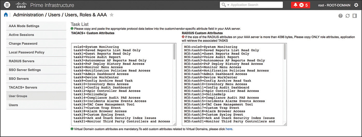
For RADIUS, the attribute NCS:role0 is enough in the final response for Prime Infrastructure to assign the corresponding group, whereas for TACACS+ you need to copy and paste all the attributes in the authentication server’s shell profile.
You can find all the steps to configure user authentication through an external server in the official administration guide:
Note
When enabling authentication through an external RADIUS or TACACS+ server, a general recommendation is to also enable fallback to local accounts in case of no response from the server or even authentication failure. This could help prevent locking yourself out, at least during an initial testing phase.
You can configure such a feature under the menu Administration > Users > Users, Roles & AAA by activating the option Enable Fallback to Local and setting it to On Authentication Failure or No Server Response. This option still allows a user to be authenticated to the internal Prime Infrastructure’s database, even if the RADIUS/TACACS+ server sends back a reject. The other option, ONLY on No Server Response, causes the authentication to fail and the user to be locked out if the RADIUS/TACACS+ server rejects the authentication.
If groups and roles provide privilege levels for performing specific administrative tasks, virtual domains allow restricting those monitoring and configuration tasks to groups of specific network devices.
When you create a new virtual domain, Prime Infrastructure presents you with the option to configure which site maps, groups of network devices, access points, and so on belong to it. Independently of how you choose to call a group of network devices, all those options in the end refer to the set of switches, access points, and the like that a user assigned to that particular virtual domain will be able to operate.
You can configure virtual domains under the menu Administration > Users > Virtual Domains.
One of the first conceptual associations we tend to do is that virtual domains can provide multitenancy capabilities end customers often ask for, which in some ways is true. On the other side, specifically for wireless deployments, you may have already encountered a common question: How can we differentiate administrative access so that, for example, some users can configure SSIDs and RF parameters only for a particular subset of access points? The short answer is that we cannot. Virtual domains can provide access to a restricted subset of access points, this is true. However, as long as an access point managed by a WLC is in the virtual domain, users from that virtual domain (with the right configuration privileges) will also be able to create any type of SSIDs on the corresponding WLC, which could then be pushed to any other access points attached to that very same WLC.
A good use of virtual domains for wireless deployments is usually to provide differentiated visibility of access points by building or floors, for example. Users of a specific office can then access a dedicated view of their office’s access points only (please note again the term view here).
As for administrative authentication and authorization, you can assign a virtual domain to users either by specifying the virtual domain they belong to when creating a local account or by dynamically assigning that virtual domain using RADIUS or TACACS+ attributes.
When creating a local account, it is mandatory to specify its corresponding virtual domain, and when authenticating a user through an external RADIUS or TACACS+ server, it is also mandatory to send back a RADIUS or a TACACS+ attribute specifying a valid virtual domain. Failing to do so will cause an authorization failure on Prime Infrastructure.
You can find the corresponding virtual domain attributes for RADIUS and TACACS+ under the menu Administration > Users > Virtual Domains by clicking on the option Export Custom Attributes on the top right of the page. Figure 6-3 shows an example of a virtual domain’s custom attributes.
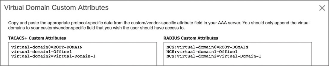
Putting authentication, group assignment, and virtual domains together, if you had to authorize users belonging to the group System Monitoring and push the virtual domain Office1, the following would be an example of the two RADIUS attributes you would need to send back to Prime Infrastructure in the final Access-Accept response:
cisco-av-pair = NCS:role0=System Monitoring
cisco-av-pair = NCS:virtual-domain1=Office1
Basic Operations
Although the features and operations described in the following paragraphs are introduced as “basic,” they still represent the foundation for properly working with Cisco Prime Infrastructure. CCIE Wireless candidates may find them crucial to speed up workflows during the lab exam too.
Working with Devices, Templates, and Audits
After having established how to manage administrative access to the management tool, one of the next steps is to use it for managing network devices. In Prime Infrastructure, you can configure a WLC through pages with a similar look and feel as the WLC’s GUI. However, one of Prime Infrastructure’s main advantages is to push multiple configuration changes at once to multiple WLCs; such a task can be achieved through the configuration templates.
Prime Infrastructure communicates with the WLC through SNMP. A WLC can send SNMP traps to Prime Infrastructure, or NetFlow records too for Application Visibility and Control (AVC) statistics. Even though Prime Infrastructure optionally asks for credentials to access a WLC via telnet/SSH/HTTPS when adding the WLC to the list of managed devices, these credentials are not needed: all monitoring operations, configuration changes, and even traps from the WLC take place via SNMP.
Common best practices when configuring SNMP communication between a WLC and Prime Infrastructure include the following:
Use SNMPv3 whenever possible, disable SNMPv1/v2c, and remove all communities on the WLC.
If SNMPv3 is not an option, use SNMPv2c, disable SNMPv1, and change the default communities with strong keywords and very selective subnet filtering.
Keep unused SNMP trap controls disabled on the WLC.
Use CPU ACLs on the WLC to restrict traffic from unneeded sources, which are not Prime Infrastructure or other network resources (more on this on Chapter 4, “AireOS Appliance, Virtual, and Mobility Express Controllers”).
To accelerate the process of importing multiple network devices sharing the same SNMP configuration and credentials, Prime Infrastructure supports credential profiles. You can create a credential profile under Inventory > Device Management > Credential Profiles and specify just once the SNMP parameters, as well as telnet/SSH and HTTP/HTTPS credentials if needed; when adding a network device to Prime Infrastructure, you can then select a previously configured credential profile instead of retyping the parameters every time.
On top of using credential profiles, you can also import multiple network devices in parallel, through a CSV file containing the same values (IP address, SNMP parameters, CLI credentials, and so on) that you would use to add those devices through the GUI.
After having added a WLC, you can apply configuration changes either through the view of the WLC itself in Prime Infrastructure or through templates. The latter is usually one of the main reasons to use Prime Infrastructure instead of going directly through the WLC’s GUI. Templates are a set of configuration tasks for specific features, which can be applied to one or more WLCs in parallel. You can create configuration templates for the WLC under the menu Configuration > Templates > Features & Technologies by browsing to the different categories under Features and Technologies > Controller in the Templates list. On top of WLC templates, you can also push templates for autonomous and lightweight access points, under the menus Configuration > Templates > Autonomous Access Points and Configuration > Templates > Lightweight Access Points, respectively.
You can deploy templates right away or schedule them for predetermined times and dates. This option enables you to address requests, such as enabling specific AP radios only during certain times of the day, through a Lightweight Access Points template, for example. You can find back scheduled AP templates and other tasks under the menu Configuration > Templates > Scheduled Configuration Task.
Note
You can schedule AP templates to enable or disable specific AP settings; however, WLC configuration templates might cause a full reconfiguration of elements (WLANs, ACLs, RADIUS servers, and so on) that already exist. For specific needs, such as scheduling the activation or deactivation of a WLAN during certain times of the day, you can rely on scheduled tasks. You can access this through the WLC’s configuration directly, under Configuration > Network > Network Devices and then by clicking your WLC. Under Configuration > WLANs > WLAN Configuration you can check the box for the WLAN you want to schedule and click the Schedule Status option. To plan the activation of an SSID during specific times of the day, for example, you will have to schedule the status twice: one for the activation and one for the deactivation.
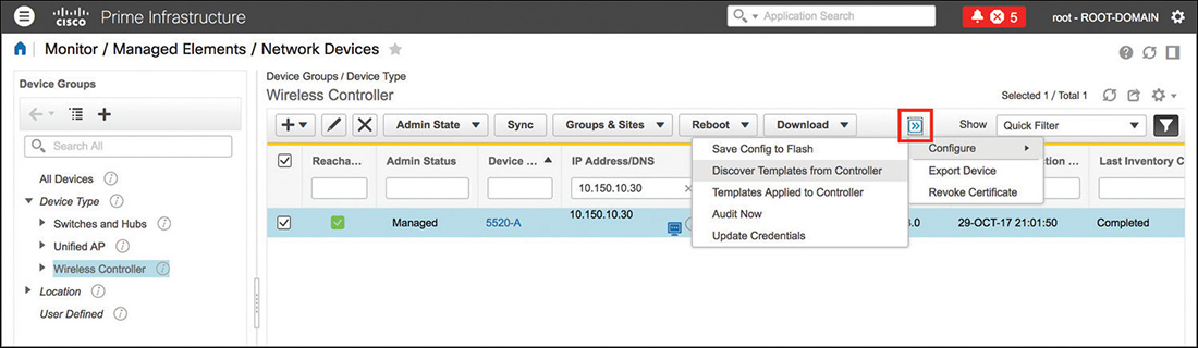
Aside from manually creating new templates, if you already configured any objects or features on the WLC before adding it to Prime Infrastructure, you can also automatically create a template for each already configured element (WLANs, RF profiles, ACLs, and so on). This process goes under the name of templates discovery, and you can launch it from the menu Monitor > Managed Elements > Network Devices by selecting the category Wireless Controller in the left panel for Device Groups, then selecting your WLC in the list and clicking Configure > Discover Templates from Controller through the option on the top right of the menu. Figure 6-4 shows an example of templates discovery in Prime Infrastructure.
After you have discovered configuration templates from a WLC, you will be able to reapply those templates and features to other WLCs, either one by one or by groups, through the Wireless Configuration Groups. You can create configuration groups under Configuration > Wireless Technologies > Wireless Configuration Groups and specify either manually created or discovered templates.
After configurations have been deployed, you can keep track of potential changes through auditing options. Under the menu Inventory > Device Management > Network Audit you can retrieve almost real-time logs on network changes, or you can also find them through the Reports > Report Launch Pad, under Compliance > Change Audit. For more proactive auditing, you can also enable notifications via syslog as changes occur; such an option is available under Administration > Settings > System Settings > Mail and Notification > Change Audit Notification.
Operating Maps
Another major interest of operating your Cisco wireless deployment through Prime Infrastructure is the additional visibility into your RF environment, rogue APs, clients, and so on when using maps.
Fundamentally, a map is a floor plan where you can place your APs. In Prime Infrastructure’s internal hierarchy and configuration, a floor needs to be part of a building, which can optionally be part of a campus. You do not need to import images for campuses and buildings, but you should import background images for floor plans before starting to place APs. When configuring dimensions for campuses, buildings, and floors, the default scale unit is in feet. You can change this to meters under the menu Maps > Wireless Maps > Site Maps ( New! ) by selecting your campus and then the option Units of Measure through the Map Properties gear icon on the top right of the page.
Note
No matter whether you scale maps in Prime Infrastructure in feet or meters, when importing them in Cisco CMX (more on this in the next sections) CMX will initially scale them in feet.
Among the final steps of a map creation, Prime Infrastructure asks you to launch the map editor to rescale the map with a ruler tool, define obstacles, zones, GPS markers, and other properties. The following are best practices for most deployments: scaling maps is key for location calculations in CMX, and although obstacles do not affect calculations for location services, they do improve the accuracy of RF heatmaps.
On top of obstacles, you might also want to add at least three GPS markers from the beginning, even before starting to place APs on the map. These GPS coordinates are exported with the map properties when working with CMX and will be available in the CMX APIs. When development teams retrieve GPS markers from a map and the client’s location coordinates on that map, they are therefore indirectly able to calculate the GPS position of the client too.
After having configured all the necessary maps, placing and orienting APs may be considered one of the most boring and repetitive tasks in the daily job of a wireless expert. Nevertheless, the precision and commitment you apply in such a task will determine the accuracy level of RF predictions, clients’ location, rogue APs location, and so on. APs can be placed on a map only if they have registered to a WLC managed by Cisco Prime Infrastructure at least once, even if for a short period of time, and even if the APs were taken offline right after the registration. Prime Infrastructure needs to “see” them once. This can facilitate deployments where you need to send APs to site relatively quickly while carrying on working proactively on their placement before the team on site installs them. You can, for example, register APs to your WLC in the lab, or other prestaging facility, get them “seen” by Prime Infrastructure, and then unplug them to send them to site. While APs are on their way to the final deployment site, you can keep working on their placements on the maps. Placing and orienting APs on maps does not affect any configuration or Radio Resource Management (RRM) calculations on the WLC. An APs’ placement is used by Prime Infrastructure to predict RF heatmaps, and by CMX to calculate location coordinates.
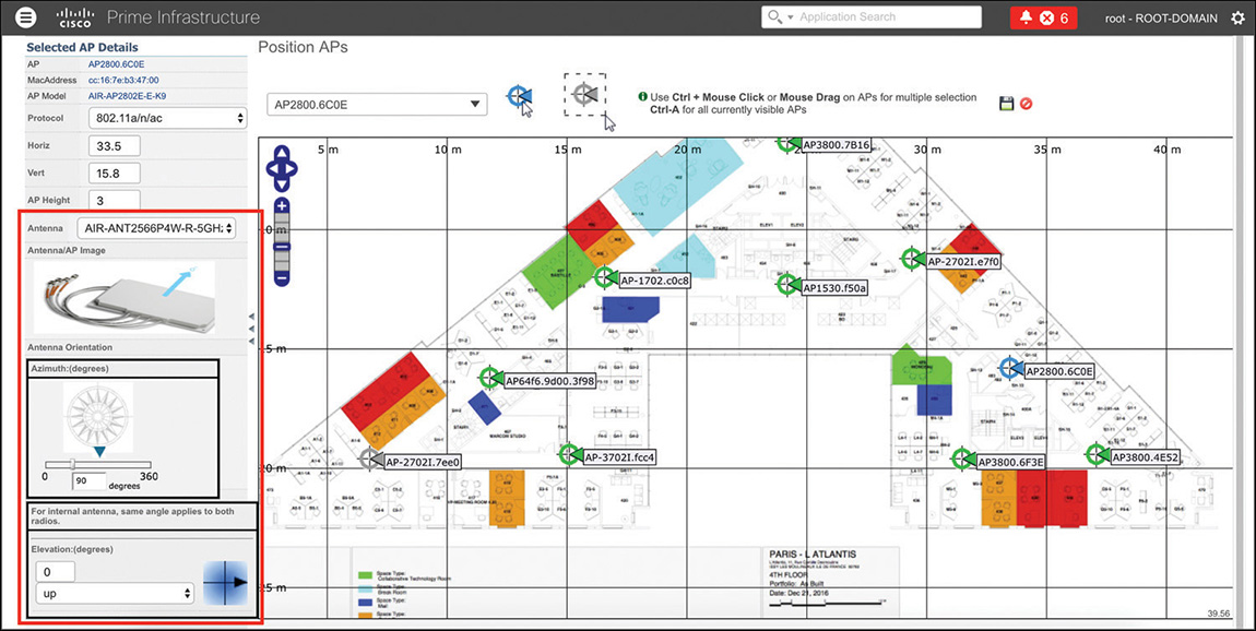
When positioning an AP on a map in Prime Infrastructure, one setting can be changed and pushed to the WLC’s configuration for that AP: the antenna model selection. If you specify the antenna model from the AP’s positioning options (see Figure 6-5), Prime Infrastructure will automatically push the antenna to gain configuration to the WLC. This particular behavior is present with what we will refer to as the “old” generation of maps under Maps > Wireless Maps > Site Maps (Deprecated), and you can see a quick example of it in Figure 6-5.
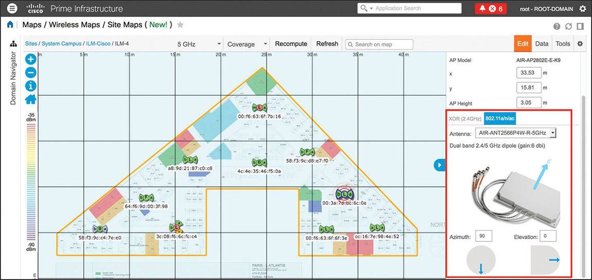
Version 3.2 of Prime Infrastructure introduced a “new” generation of maps, as shown in Figure 6-6, which do not push the antenna gain to the WLC when the antenna model is configured, while placing an AP on a map. You can access new generation maps under Maps > Wireless Maps > Site Maps (New!).
However, if you still use the old generation of maps, also available in version 3.2 (or any previous version up to 3.1.x), modifying the antenna model when placing the AP on a map also pushes that configuration to the WLC. Another common technique for configuring an antenna model, both on Prime Infrastructure’s maps and on the WLC, is to create a Lightweight Access Points configuration template, where you can configure the antenna models under the 802.11a/n/ac and 802.11b/g/n tabs.
Along with AP placement, antenna orientation is the other essential operation for obtaining realistic heatmaps and accurate clients, interferers, and rogue APs location on maps.
When orienting an antenna, keep in mind some rules to help you:
For the vast majority of installations, you might need to configure the orientation of both antennas, on the 2.4 GHz and on the 5 GHz radios. If one radio is disabled, you might want to ignore its orientation; however, it is recommended that you orient all antennas, even those that are disabled, just in case you enable them in the future.
There are two orientations for each antenna: azimuth and elevation. Azimuth is the antenna orientation viewed from above, and elevation is the antenna orientation viewed from the side. You can visualize the orientation of an antenna as an arrow, which you can represent in different ways, depending on the type of antenna.
When configuring orientations, you should first position the azimuth and then the elevation; such an order is logically easier to follow. Therefore, you can first imagine orienting the antenna’s arrow as viewed from above and then as viewed from the side.
For APs with internal antennas, the orientation is represented by an arrow beaming from the middle of the AP (where you can often see the Cisco logo or the LED) and pointing toward the upper side of the AP, and toward where all the Ethernet ports are for the vast majority of indoor AP models up to the 1800/2800/3800 series, as shown in Figure 6-7, for example.

Figure 6-7 Antenna Orientation for APs with Internal Antennas
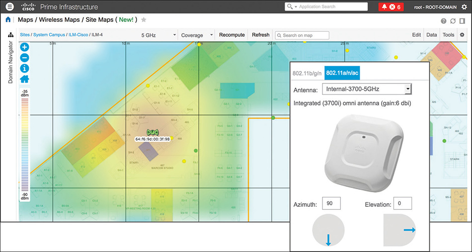
By default, Prime Infrastructure orients an AP with internal antennas with an azimuth of 90 degrees and an elevation of 0 degrees. This corresponds to an AP mounted with the upper side of the Cisco logo pointing south (toward the lower part of the floor map) and the Cisco logo facing down to the ground. It’s the typical installation of an AP on the ceiling, and Figure 6-8 shows an example of such an orientation in Prime Infrastructure.
Omnidirectional antennas, as their name suggests, radiate in all directions. Therefore, suppose the real azimuth of an AP with internal omnidirectional antennas is different from what you configured on the map. For example, you may have wrongly configured an azimuth of 180 degrees (the Ethernet ports show as facing west, while actually mounted facing south). Despite this difference, the heatmap prediction or location services should still be accurate, precisely because of the omnidirectional nature of the antennas. Nevertheless, we recommend making the extra effort of configuring both azimuth and elevation to reflect the real antennas’ orientations.
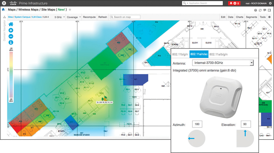
This care in antenna orientation is especially important for APs and antennas mounted on walls. For example, suppose that an AP with omnidirectional antennas is vertically mounted on an east wall, with the Cisco logo facing west and the Ethernet port(s) facing up to the ceiling. You should configure an azimuth of 180 degrees (that is, first the arrow pointing left, as viewed from above) and an elevation of 90 degrees (that is, the arrow pointing up as viewed from the side), as shown in Figure 6-9.
For external dipole omnidirectional antennas (AIR-ANT2524DB-R, AIR-ANT2524DG-R, and AIR-ANT2524DW-R), you should think of the arrow as perpendicular to the longitudinal axis of the antenna and to either of its “flat” sides. By default, Prime Infrastructure orients external dipole antennas with an azimuth of 90 degrees and an elevation of 0 degrees. This corresponds to the antenna’s tip pointing down to the ground and either of its “flat” sides parallel to the X axis of the map. When using external antennas, the AP orientation does not matter, because only the external antenna’s installation and orientation determines the coverage area.
As an example, a dipole antenna with an azimuth of 0 degrees and an elevation of 45 degrees corresponds to the “donut” shape coverage area tilted down to the left, when looking at it from the south side of the map. You can see an example of this configuration in Figure 6-10.
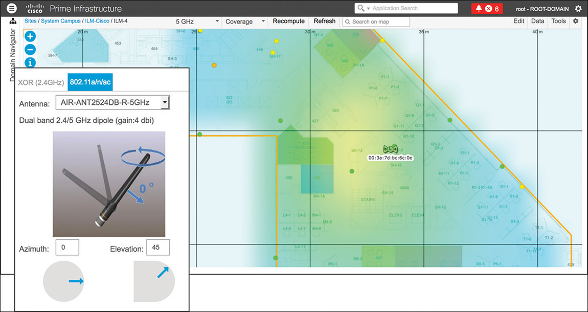
Figure 6-10 Dipole Antenna Orientation with an Azimuth of 0 Degrees and an Elevation of 45 Degrees Another example, as shown in Figure 6-11, could be a dipole antenna with an azimuth of 0 degrees and an elevation of −45 degrees, which corresponds to the “donut” shape coverage area tilted down to the right when looking at it from the south side of the map.
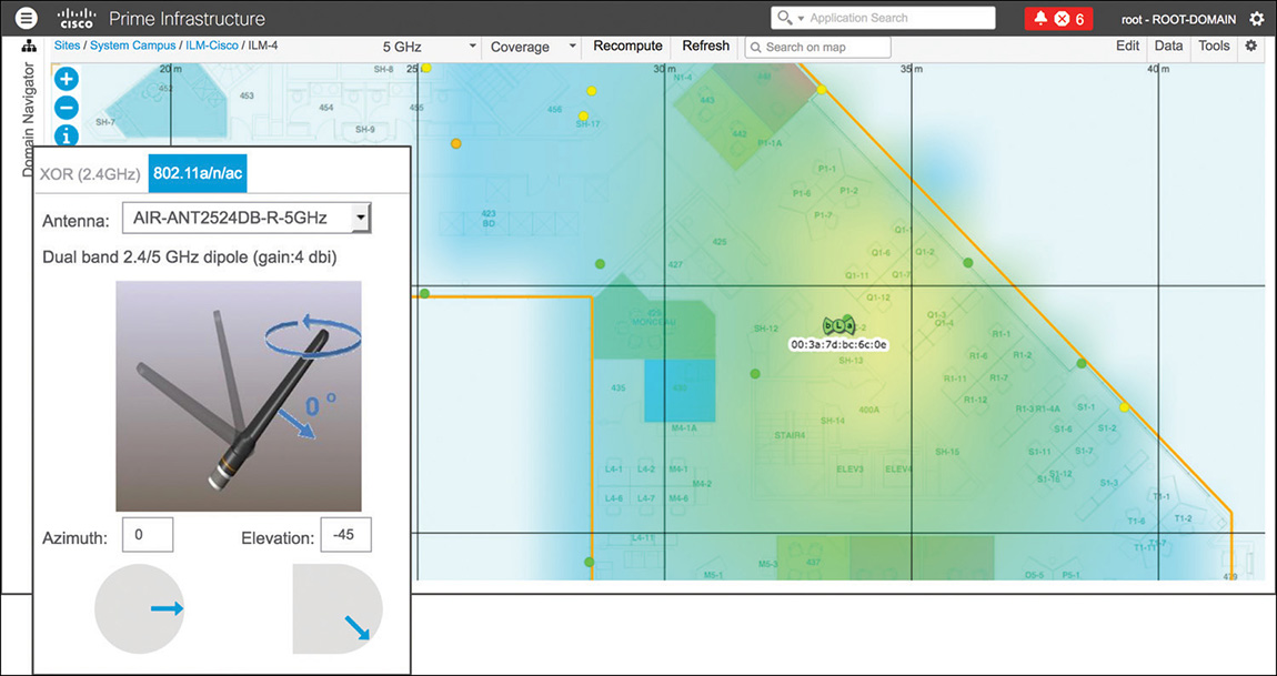
Figure 6-11 Dipole Antenna Orientation with an Azimuth of 0 Degrees and an Elevation of −45 Degrees In the previous examples, to get an elevation of −45 or 45 degrees in the actual installation, you will have to turn the dipole in such a way that the antenna’s bolt will allow you to tilt it. The arrow orientation does not change between one side and the other, because you are dealing with an omnidirectional antenna.
External patch-like antennas (AIR-ANT2524V4C-R, AIR-ANT2566P4W-R, AIR-ANT2566D4M-R, and AIR-ANT2513P4M-N) have an orientation arrow originating from the center of the antenna’s plate, perpendicular to the plate (pointing away). By default, Prime Infrastructure orients such antennas with an azimuth of 90 degrees and an elevation of 0 degrees, as shown in Figure 6-12. This means that the antenna is vertically mounted, with the plate facing south and its cables (for example, for an AIR-ANT2566P4W-R) pointing down to the ground (the orientation arrow points south as well).
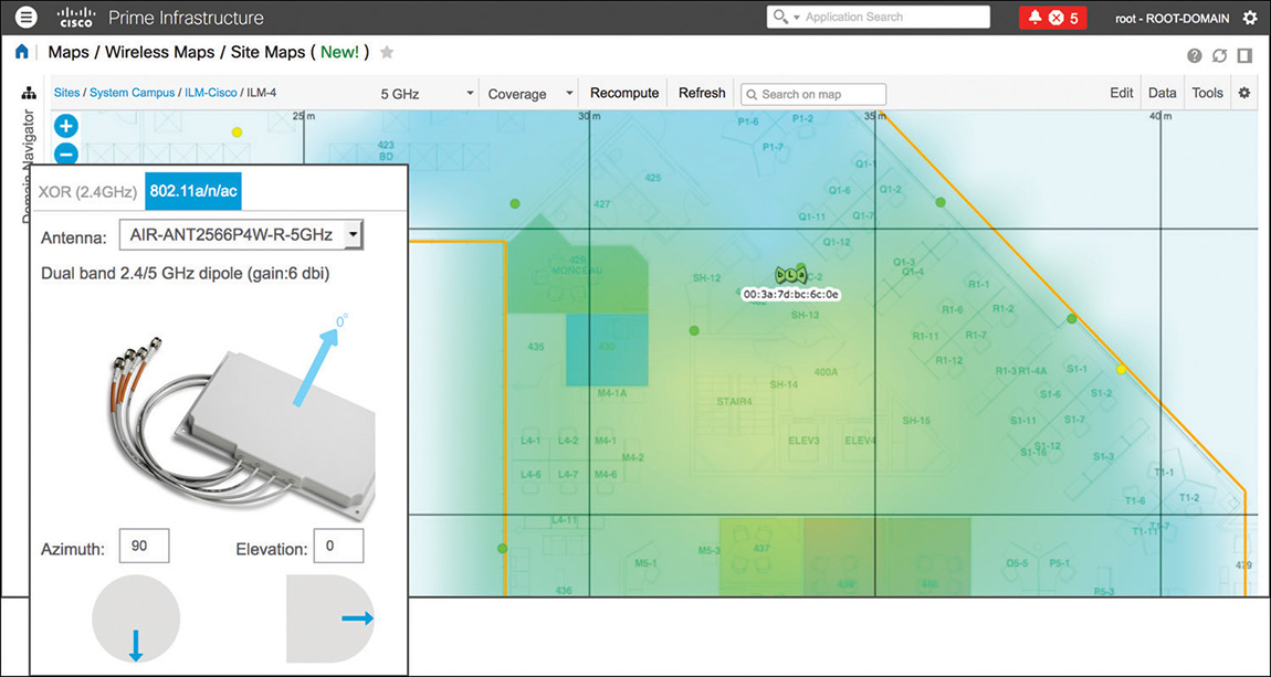
Figure 6-12 Patch Antenna Orientation with an Azimuth of 90 Degrees and an Elevation of 0 Degrees Similarly, an AIR-ANT2566P4W-R with an azimuth of 90 degrees and an elevation of −90 degrees, as in Figure 6-13, would be mounted with its plate facing down to the ground and the cables’ side pointing north: the orientation arrow in such a case would point down to the ground too. This would correspond to an antenna horizontally mounted, on the ceiling for example, with its cable connectors pointing north on the map.
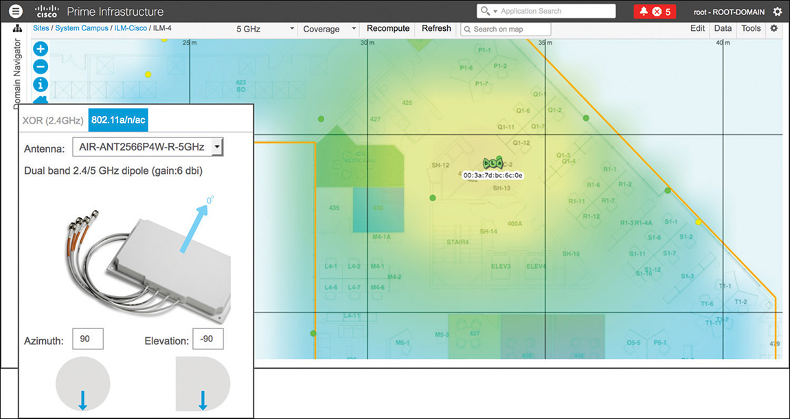
Figure 6-13 Patch Antenna Orientation with an Azimuth of 90 Degrees and an Elevation of −90 Degrees
Even though antenna orientations may not sound very intuitive at the beginning, one of the best ways to get a consistent grasp on them is to try out different combinations in Prime Infrastructure and check how the predicted heatmap varies accordingly.
Note
With the old generation of maps, elevation values could go from 0 to 90 degrees, with an extra orientation of UP or DOWN. With the new generation of maps, elevation values range from −90 to 90 degrees. The supported orientations are the same: 0 to 90 degrees DOWN in the old generation maps correspond to 0 to −90 degrees with the new generation and, in a similar way, 0 to 90 degrees UP in the old generation maps correspond to 0 to 90 degrees with the new generation maps.
High Availability
For additional redundancy and availability, you can deploy Prime Infrastructure servers as HA pairs: the high availability model is always with two servers, one active and one standby. The monitoring and synchronization services between primary and secondary servers are SSL based and run on TCP ports 1522 (Oracle/JDBC database connections) and 8082 (health monitoring via HTTPS). The two servers need IP reachability, of course, and if you choose to deploy them on the same VLAN, you have the option of configuring a Virtual IP for the HA pair. This option usually has the advantage of letting you point your network devices to one single management IP for SNMP traps and syslog, for example. Each Prime Infrastructure server will keep using its real management IP to source all other traffic to those network devices.
If you choose to deploy Prime Infrastructure servers on different subnets or not to configure a Virtual IP, you need to make sure that network devices are sending SNMP traps and syslog messages to the IPs of both servers, not to lose data in case of failover.
You have the option of two failover modes, manual or automatic, both having their pros and cons. Manual failover, as the word says, does not have the advantage of automatic recovery if the active server fails. However, this mode could also avoid “split brain” scenarios where each server automatically promotes itself to active because of a network reachability failure. Manual mode also avoids the issue of continuous failover because of potential network latency issues between both nodes.
The high availability configuration is relatively straightforward and can be followed through the official administrator’s guide:
On top of the official guide, as a quick review of the requirements to keep in mind when setting up high availability for Prime Infrastructure, here are the main steps you should consider:
Plan the high availability deployment model by choosing between having a Virtual IP for your pair of Prime Infrastructure servers or keeping your servers reachable on their respective IP addresses if they cannot be deployed on the same subnet.
Verify that both your primary and secondary servers will be installed with the very same software versions, patches, and packages.
After the primary server’s installation, while installing the secondary server, verify that you specify the option for this server to be used as a secondary for HA, and note down the authentication key that you will be asked right after this step: you will be asked for this key on the primary server when activating HA.
After installing the secondary server and updating it, if needed, to the same version/patch/device bundle as the primary, on the primary itself, you can activate high availability through the HA Configuration tab under Administration > Settings > High Availability. You will be asked for the secondary server’s information, such as FQDN/IP and authentication key, as well as for options such as the Virtual IP or the failover mode (for example, manual versus automatic).
The high availability setup itself might take some minutes, after which you will be able to connect to your Prime Infrastructure pair either through the Virtual IP, if you chose to enable such an option, or through the primary or secondary server’s IP, depending on which one is active at a given time.
Monitoring Tools: Troubleshooting Clients and Working with Reports, Alarms and Events, and Notifications
Along with managing network devices and configurations, another main goal of Prime Infrastructure is to provide network administrators with troubleshooting and reporting tools. Although CCIE-level experts will prefer debugs on the WLC or AP, in daily network operations having a centralized tool with data from different sources could be an easier starting point to isolate issues.
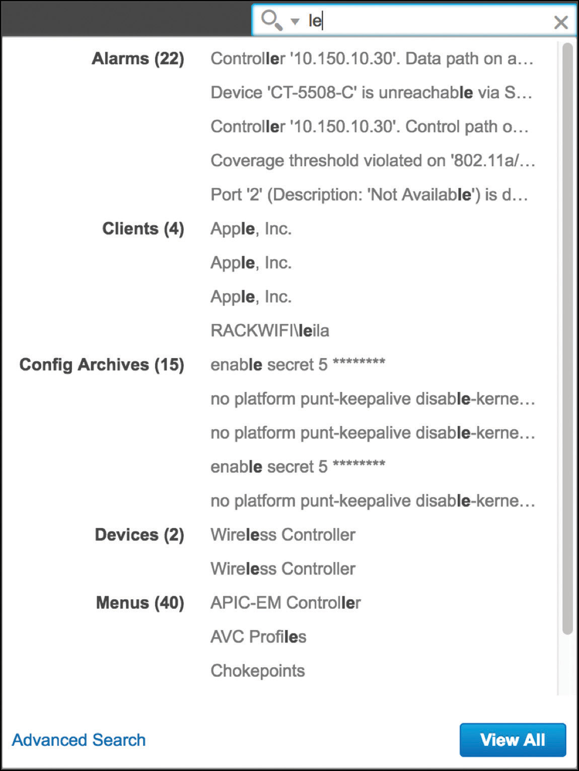
Comparing troubleshooting methodologies is not the primary goal of this book, but as a general guideline, one of the fastest and easiest options for looking up a client’s details (or any other device’s details) in Prime Infrastructure is through the contextual search field on the top right of the GUI, as shown in Figure 6-14. As soon as you start typing a username, a MAC address, an IP address, and the like, Prime Infrastructure suggests any elements that are possibly related to what you are typing. This is an easy way to immediately jump to a client’s details, instead of having to navigate through a list of clients under Monitor > Monitoring Tools > Clients and Users and then filtering through specific values.
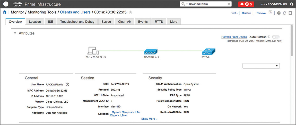
Client details are organized in different tabs, to also provide additional logs and tools from other resources on top of Prime Infrastructure. The Overview tab consolidates information mainly from the WLC, with some details from Cisco ISE and CMX if you have integrated such solutions to Prime Infrastructure. Although these details are not in real time (as compared to WLC or AP CLI debugs), they are still a good starting point for a high-level view of policies applied to the client, for example, and in particular, to understand through which APs the client associated and disassociated (thanks to the Association History widget). Even though this is technically not a location feature, the association history might in some cases indirectly help you trace a client’s path at some levels, or even isolate whether clients are “jumping” between APs too far from one another. Complementary to these types of data, the Statistics widget, showing the client’s RSSI and SNR history, could provide useful information if your clients were experiencing radio or coverage issues, for example.
The Location tab integrates data retrieved through the former location solution Mobility Services Engine (MSE). Prime Infrastructure also supports integration with CMX 10.3 to locate wireless clients and interferences on the maps. However, location information in the client’s details (page) is available only with MSE 8.0. On top of displaying the specific portion of the floor plan, where a client is located, this page also allows you to replay the client’s location history.
Right next to location data, Prime Infrastructure also hosts a dedicated tab for reporting authentication successes and failures from ISE. From this page, you can directly monitor failure reasons and, although Prime Infrastructure displays only the main reason for the failure, you can also cross-launch the monitoring page on ISE directly to look at all the failure’s details. When adding ISE to Prime Infrastructure, you should keep in mind the following prerequisites:
Prime Infrastructure communicates with the ISE server(s) persona running the Monitoring services.
In case of a standalone ISE server, you can add that single ISE server to Prime Infrastructure.
In case of a distributed ISE deployment, you should add the primary monitoring node, and the secondary too, if you want to keep collecting authentication logs in case of a failover of the primary monitoring node.
The ISE account required by Prime Infrastructure needs to have access to the Operations tab in ISE and be part of the MnT Admin group or higher, such as the Super Admin group.
Aside from authentication logs in a dedicated tab, Prime Infrastructure also displays the policies applied by ISE during the authentication process in the client’s Overview tab. These could provide you with very useful information, such as the Authorization Profile, the Posture Status, the TrustSec Security Group, and others. Figure 6-15 shows some additional examples of tabs for client troubleshooting.
Other tabs providing more hints on the overall client’s connection status are those for Clean Air and Events, but note that these are not necessarily in the same order as in the (WLC’s) GUI. These pages contain information about potential interferences affecting the AP where the client is connected, as well as the most recent SNMP traps (that is, events) from the WLC concerning that AP and the client.
Prime Infrastructure also has dedicated tabs for collecting and reading logs and debugs from the WLC for a specific client that you are monitoring. These are the Troubleshoot and Debug, Syslog, and RTTS (Real Time Troubleshooting) tabs. As a CCIE candidate, you will probably prefer to use CLI debugs and commands on the WLC and AP directly. Nevertheless, these tabs find their purpose for network operations teams, who can collect some initial data and open a technical support case from a single interface.
If, instead of almost real-time troubleshooting and data, you need to access historical information about clients but also networks, devices, and the like, you can rely on the reporting options under Reports > Report Launch Pad. Here you can create reports for several categories, schedule them to run periodically, and also have the report(s) sent via email after each run.
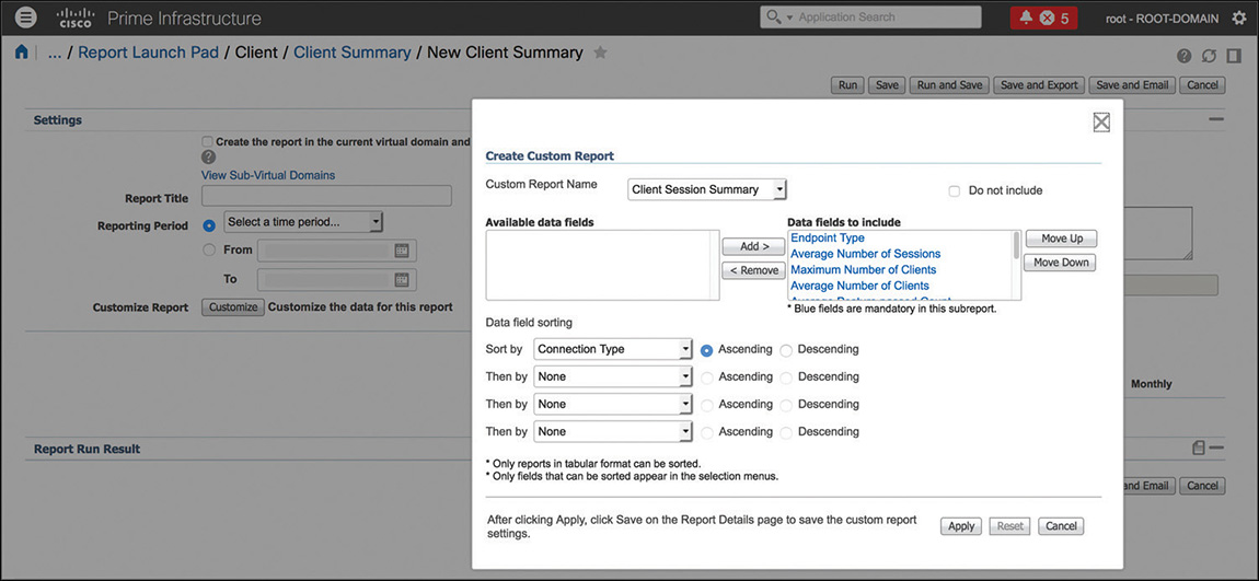
Depending on the specific category, a report includes different types of information that you can filter by customizing which columns to include in the report itself, as shown in Figure 6-16. If one of the default reports seems to have roughly the information that you are looking for, you may want to verify whether there are additional columns that you should include, through the Customize option. Under the same customization parameters, you also find the settings to sort the report’s data by specific fields.
Note
Reports for Identity Services Engine do not run on Prime Infrastructure natively. When clicking an ISE reporting category, you will cross-launch the ISE monitoring interface.
In addition to the preconfigured reports, Prime Infrastructure supports options to composite them or create customized reports.
Under the Report Launch Pad, on the left menu, among different categories is one called Composite, with a suboption for Composite Report. Here you can select some reporting categories from different report types that should be included within a single report.
In a similar way, the Custom Reports page enables you to select some other common categories and run their data collection in the same report, instead of, for example, having to generate two or more separate preconfigured reports for each one of those. Composite and custom reports are in the end two similar options for achieving the same goal of including different categories in the same report.
If you choose to schedule reports and let Prime Infrastructure store files locally, their folder path is /localdisk/ftp/reports. You can change this, along with the files retention period, under Administration > Settings > System Settings > General > Report.
You can find even more tools for supervising network operations under the Monitor menu. On top of the preconfigured pages to monitor specific features, such as Radio Resource Management (RRM), access point radios, or even clients and network devices, through this menu you can configure events, alarms, and notifications.
Events are SNMP traps and syslog messages received by Prime Infrastructure from network devices. They are logged as events on the GUI. Alarms are alerts raised following from the correlation of one or more events.
You can configure new events to be reported, following from a specific SNMP trap under Monitor > Monitoring Tools > Alarms and Events, by clicking the Custom Trap Events button under the Events tab. Here you can either choose from some of the predefined MIBs or upload new MIBs.
Alarms are preconfigured, and you cannot create new ones. However, through specific triggers, you can change the severity of an alarm through Alarm Policies. Another option is to change the default severity of an alarm under Administration > Settings > System Settings > Alarms and Events > Alarm Severity and Auto Clear.
An alarm can have its status set to one of these three types: Not Acknowledged, Acknowledged, and Cleared. Alarms are not acknowledged by default, which means that they stay in the Alarms and Events table until some other action is taken. When you acknowledge an alarm, you remove it from the Alarms and Events table and, even if the events that generated the alarm recur again within the next 7 days, Prime Infrastructure will not trigger the alarm again. When you clear an alarm, you also remove it from the Alarms and Events table. However, Prime Infrastructure regenerates the alarm as soon as the associated events reoccur.
When working with alarms, events, and monitoring options, you may also want to configure notifications for specific events. Prime Infrastructure supports sending notifications either via email or SNMP traps. You can configure receivers under Administration > Settings > System Settings > Mail and Notification > Notification Destination. If you decide to configure notifications via email, you should also specify the Mail Server Configuration right above the previous menu.
The next step in configuring notifications are the Notification Policies themselves, either under Monitor > Monitoring Tools > Notification Policies or under Administration > Settings > System Settings > Alarms and Events.
A notification policy defines for which alarms, on which network device categories, Prime Infrastructure should send an email or SNMP trap to the configured destination email address or SNMP trap receiver. An example is sending an SNMP trap when a rogue AP event triggers the corresponding alarm.
Configuring Jobs
Prime Infrastructure keeps collecting information from the network and the resources it interacts with through automatic or manual tasks, referred to as jobs. You can find the full list of available jobs under Administration > Dashboards > Job Dashboard. The main goal of such jobs is to keep refreshing the status of the network devices, their services, configurations, and so on without the administrator’s manual intervention. For this reason, the vast majority of these jobs are scheduled to run automatically.
As an example, under the System Jobs > Status group, you can find the Wireless Configuration Audit job for synchronizing Prime Infrastructure with the latest configuration on the WLC itself. It is usually scheduled to run once a day every day, but you can edit the frequency.
Although usually not needed because by default all necessary jobs run automatically, you may, for example, want to check a specific job’s schedule and collection status in case you cannot see data or statistics being updated for certain devices or services.
Security Operations
Security operations for wireless in Prime Infrastructure include three main functions: configuration auditing, rogue access points monitoring, and wireless intrusion prevention systems (wIPS). The latter is tightly related to the Mobility Services Engine, and we delve more into it in the next sections of this chapter.
Through configuration auditing, Prime Infrastructure performs different checks against a predefined list of settings and assigns a so-called Security Index to the wireless deployment. These predefined settings include options such as Telnet/SSH configuration, client exclusion measures, Management Frame Protection (MFP) parameters for WLANs, and so on. You can access the Security Index under Dashboard > Wireless > Security. Whenever you configure an option in a way that it is deemed as “optimal” (in terms of security best practice compliance), Prime Infrastructure raises the overall Security Index score, where a score of 100 represents the maximum value. However, not reaching a Security Index of 100 does not mean that your wireless network is not secure. You should consider such an index as a general indicator for all the security-related elements that you could configure in all the WLCs managed by Prime Infrastructure. Some of these elements are well-known best practices, such as making sure that the default SNMP communities are not enabled, but not reaching the maximum score does not necessarily mean that your networks are unsecure or unprotected.
Note
The Security Index that is evaluated against the WLCs’ configurations is updated by Prime Infrastructure after each run of the Wireless Configuration Audit job (mentioned in the previous section).
Under the same Security dashboard, you can see a preview of wIPS attacks and rogue access points detection. From here, by clicking the different counters, you can directly access the specific alarms and events raised for those categories.
We described rogue access points detection, classification, and mitigation on the WLC previously in this book. Prime Infrastructure receives SNMP traps from the WLC about rogue access points and consolidates them into alarms, which you can find under Monitor > Monitoring Tools > Alarms and Events and the Rogue AP tab. By default, Prime Infrastructure assigns an Information severity to friendly rogue APs detection, a Minor severity for unclassified rogue APs detection, a Major severity for malicious rogue APs, and a Major or Critical severity for custom rogue APs. This classification depends on the severity score of the custom rogue classification rule on the WLC.
A common requirement in today’s wireless networks is to be able to locate and manage rogue access points on a map. If you don’t need to locate more than one rogue access point at a time, Prime Infrastructure natively supports such an option without the need for additional components, such as the Mobility Services Engine (MSE). You can find such an option called Ondemand Location Map under the rogue AP alarm details, as shown in Figure 6-17.
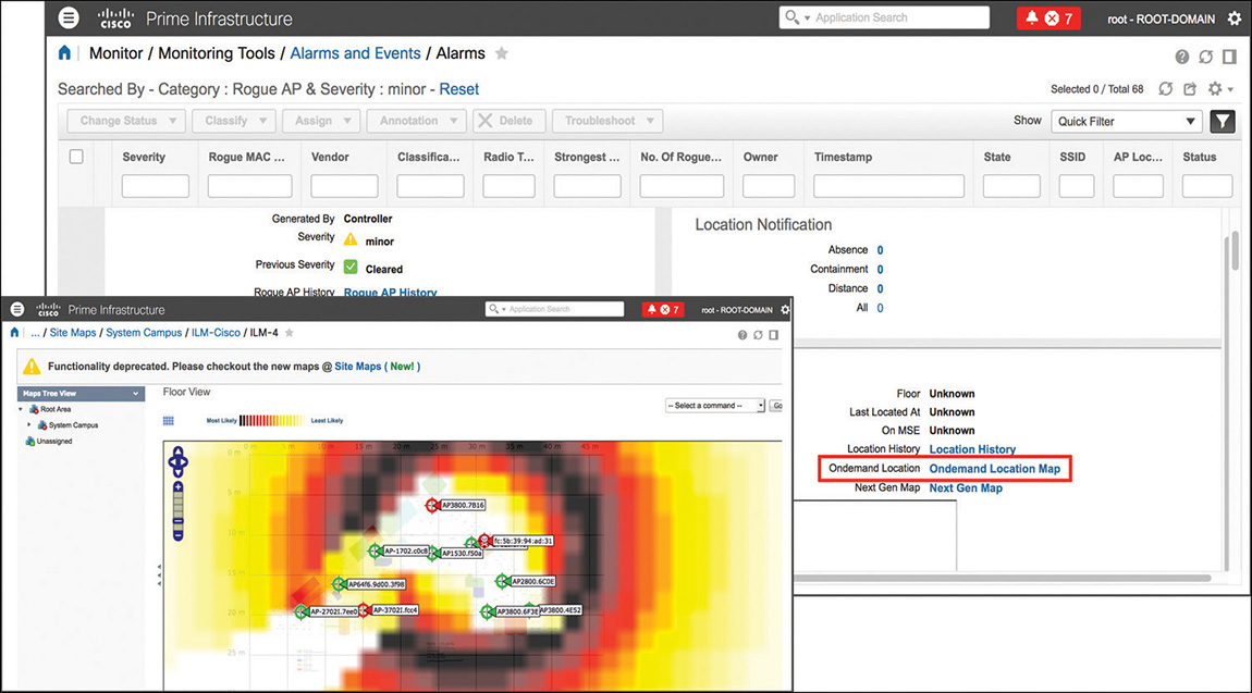
Although without an MSE you cannot display a rogue AP location in the alarm’s details or locate multiple rogue APs at once on a map, you can still trigger an on-demand location. However, note that this feature works with old generation maps only. We keep referring to MSE when talking about rogue access points’ location. This is because, at the time of this book’s writing, the current version (10.3) of the more recent Cisco location solution, Connected Mobile Experiences (CMX), does not support such a feature, which is expected for a future version.
On top of rogue policies, contention, and techniques on the WLC to detect whether rogue access points might be on your wired network, Prime Infrastructure also supports an additional option to determine whether a rogue AP may be connected to one of the Cisco switches managed by Prime Infrastructure. This feature is called Switch Port Tracing (SPT), and you can launch it directly from the rogue AP alarm’s details. You can configure SPT to be launched automatically or manually, with a series of additional options that you can find under Administration > Settings > System Settings > Network and Device > Switch Port Trace (SPT) > SPT Configuration. Following a rogue AP detection and an SNMP trap event from the WLC, after the correlated alarm is generated, Prime Infrastructure can determine via the Cisco Discovery Protocol (CDP) to which Cisco switch the Cisco access point that is detecting the rogue AP is connected. However, you must enable CDP on your Cisco access points and switches for SPT to work. Cisco switches should also be managed by Prime Infrastructure via SNMP, because after having found where the detecting Cisco access point is connected, Prime Infrastructure queries the content addressable memory (CAM) table of the switch via SNMP. By doing so, it tries to find out if one of the rogue access point clients’ MAC addresses is present, or if the MAC address of the rogue AP itself is present in the CAM table (plus or minus 1 and 2 to the right-most significant byte). For example, if the rogue AP’s detected radio MAC is FC:5B:39:94:AD:31, in addition to that specific MAC, Prime Infrastructure will search for FC:5B:39:94:AD:30, FC:5B:39:94:AD:32 (minus and plus 1 to the right-most significant byte), and FC:5B:39:94:AD:2F, FC:5B:39:94:AD:33 (minus and plus 2 to the right-most significant byte). This technique will increase the chances of finding the rogue AP’s Ethernet MAC in the switch CAM table, because usually the radio MAC is derived from the Ethernet MAC by adding or subtracting 1 or 2 to the right-most significant byte (sometimes even more than just 1 or 2, but in that case, the SPT search could demand too many resources). If Prime Infrastructure does not find the rogue AP on the first switch, it queries that switch for its neighbor switches via CDP, and then starts analyzing those neighbors’ CAM tables, provided that it is managing them, and so on. If Prime Infrastructure finds the rogue AP connected to one of the switches’ ports, you then have the option to disable that port. Figure 6-18 shows a quick example of SPT.
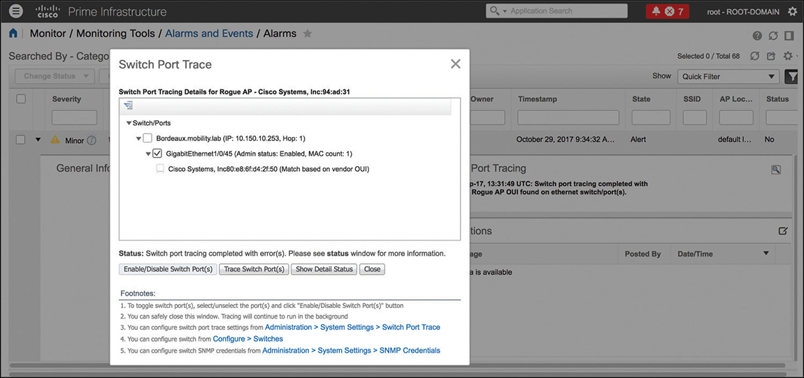
Depending on the network size, SPT could take some time and resources to complete. For such a reason, you can find options to configure how many rogue APs and switches Prime Infrastructure should query in parallel when SPT is launched. You can also configure the maximum number of CDP hops, which represents how many CDP neighbor searches Prime Infrastructure should use when querying switches starting from the Cisco access point that detected the rogue AP. You can access these settings under the aforementioned SPT Configuration menu.
For the sake of simplicity, so far we have mentioned that switches used for SPT should be managed by Prime Infrastructure, but this is not entirely accurate. You can add a switch to Prime Infrastructure, manage it from there, and of course run SPT. In such a managed scenario, that switch consumes one or more license tokens in Prime Infrastructure, depending on the switch model and configuration. However, you can also add switches in Prime Infrastructure with the option Switch Port Trace for the license level, in which case the switch does not consume any licenses.
To manually launch SPT, you do not even need to add switches in Prime Infrastructure, as long as you enter the correct SNMP parameters for the switches in your network under the Manual SPT configuration, and don’t forget that enabling CDP on all Cisco APs and switches is always a prerequisite.
Mobility Services Engine and Connected Mobile Experiences
Location services have been a major component of Cisco wireless networks since the first days of controller-based architectures. The very first location solution was called Location Appliance, which in turn evolved to Mobility Services Engine (MSE). The main changes included new hardware platforms, performances, and the introduction of wIPS, along with other improvements in software features and fixes. Nevertheless, the basics of the original location algorithms are still used nowadays, even in the most recent code, of course with the necessary adjustments for more up-to-date wireless clients and environments. The location service itself has always been referred to as Context Aware Services (CAS), which is still used in some menus and previous license models. Both the Location Appliance and MSE solutions supported APIs for external resources to collect location data and take advantage of them for third-party solutions, such as RFID tags, analytics engines, way finding applications, and so on.
In 2012 Cisco Systems completed the acquisition of a company called ThinkSmart, whose primary business was an analytic engine integrating via APIs to MSE and which provided tools to display statistics such as visitors count, dwell times, most commonly used paths, and the like. Cisco integrated ThinkSmart’s tools in the location solution starting with MSE 7.4 and called that subset of menus Connected Mobile Experiences. Within a few months the market responded positively to such an offer, and the whole solution has been readapted for new business needs, while leaving the former network location and management features to MSE. CMX became a new standalone solution, with its own GUI and services, with MSE still available to keep supporting all the previous use cases. To better differentiate the two, MSE kept using the former version numbering, whose latest one is 8.0 at the time of this book’s writing; CMX started from version 10, and the current one chosen for the Wireless CCIE exam is 10.3.
MSE and CMX are not 100% equivalent for the time being, but the plan is for CMX to eventually replace MSE for all the location options and for MSE to keep supporting wIPS services. The following are some of the major common options and differences between MSE and CMX:
The acronym MSE is still used to indicate the hardware appliance AIR-MSE-3365-K9, on top of which the code for either MSE or CMX could run. CMX is generally always used to indicate the new software solution for location and other services. So you could find examples in the configurations guides stating that CMX runs either on the MSE appliance or as a virtual machine. Throughout this book we refer to CMX and MSE respectively as the new and former software solutions.
CMX supports three types of virtual machine installations (high-end, standard, and low-end) and a physical appliance installation, depending on the scale and services you would like to support. Although it could technically run for lab purposes, hyperlocation is officially supported on high-end virtual machines and the 3365 physical appliance only. The official “Cisco Connected Mobile Experiences (CMX) 10 Ordering and Licensing Guide,” at https://www.cisco.com/c/en/us/solutions/collateral/enterprise-networks/connected-mobile-experiences/guide-c07-734430.html, and “Cisco Connected Mobile Experiences Data Sheet,” at https://www.cisco.com/c/en/us/solutions/collateral/enterprise-networks/connected-mobile-experiences/datasheet-c78-734648.html, contain all the numbers for scalability and virtual machine specifications.
Both MSE and CMX use Probe RSSI as the most commonly deployed location technique (more on this in the next sections) to achieve an accuracy of around 5–10 meters for wireless clients.
MSE can locate wireless clients, interferers, RFID tags, and rogue APs and rogue clients. CMX can locate wireless clients, interferers, RFID tags, and Bluetooth Low Energy (BLE) beacons.
Prime Infrastructure supports data from MSE to display located devices (wireless clients, interferers, RFID tags, and rogue APs and clients) on maps and uses those data for client troubleshooting, interferences-related widgets, and reports. CMX 10.3 is supported with Prime Infrastructure 3.2 for clients and interferers location on maps only.
MSE is the only solution supporting wIPS.
CMX is the only solution supporting FastLocate and Hyperlocation.
Location Technologies and Techniques
Tracking and positioning systems have been around for decades now, but more recently the market started asking for additional accuracy and real-time location to address new needs related to how networks could interact with end users through mobile devices and applications. Such new needs might include visitors’ flows analytics, campaigns advertisements, wayfinding applications, and so on.
Although outdoor location technologies such as GPS could still be a good complement, indoor location can usually better be achieved through radio standards such as Wi-Fi or even the more recent Bluetooth Low Energy (BLE). Throughout the next paragraphs we present some of the most common indoor location techniques, while leaving some special notes for BLE at the end: even if not all these techniques are directly included in the Wireless CCIE blueprint, you may still benefit from some additional details in your daily job as a wireless expert.
Indoor tracking technologies are often also referred to as Real-Time Location Systems (RTLS) and can adopt different approaches.
Cell of Origin and Presence
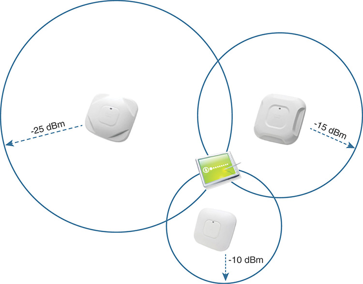
This is the most basic location technique, which consists in determining the closest antenna to which the client is associated or simply passing by, by using the strongest Received Signal Strength Indicator (RSSI) value, as shown in Figure 6-19.

Although we could still graphically represent a cell of origin on a map, through a big circle for example, this would still be inaccurate. For such a reason, cell of origin is more commonly related to the notion of presence, which in CMX allows collection of statistics such as visitor counts and frequency, dwell times, and so on, but not to place a specific client on a map.
A common misconception is to use the notion of presence and wireless in general to count visitors of a venue, a shopping mall, a museum, or an office. Although such a technique does count visitors in terms of wireless clients, it cannot be fully representative for all the visitors flowing through a certain location. Many visitors could have Wi-Fi turned off on their mobile devices, and many others could have no mobile devices at all. A better use of presence would be as an indicator of how crowded a specific location can get during a certain time of the day, month, or year, and such information could generally be a complement for other big data sources and calculations.
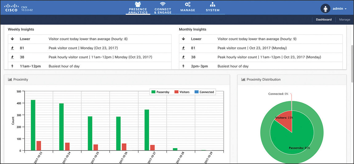
The CMX installation process initially asks you to choose whether to configure CMX for Location or Presence. If you choose Presence, CMX will activate a dedicated GUI, called Presence Analytics, with graphs for visitor counts, dwell times, frequency of visits, and so on, but without any concept of location on plans, as shown in Figure 6-20. Counters are based on APs from specific groups, or sites, that you declare on CMX directly, so not to be confused with AP Groups on the WLC for example. All the options for Presence, as well as Connect and Engage (more on this in the next sections) that you activate through the Presence installation choice are available with the CMX Cloud offer too: CMX Cloud is literally a CMX Presence instance hosted on the Cisco cloud.
An advantage of the CMX Presence installation, because it is not providing any form of location on maps, is that it is completely independent from Prime Infrastructure and its plans. To deploy presence services and analytics, you technically need one single access point, without any need for placing it on a map and orienting its antennas. On the other side, many customers quickly find new needs and use cases on top of basic presence statistics, which make them move quickly to a full CMX Location installation.
You can obtain almost similar presence statistics with the CMX Location installation and its corresponding Analytics dashboard. Although not applicable to all deployments because it could set wrong expectations, a location deployment not respecting all the prerequisites for precise location calculations (see the next section) could still be used to obtain presence data only, in terms of devices’ counts and dwell times on a specific site, or map. However, in this case the end customer should thoroughly accept not to trust other location type data obtainable through CMX, precisely because the deployment did not respect all the prerequisites for location in the first place. A reason to “hijack” a CMX Location installation for presence use cases could be to concentrate on just one server data for some sites needing presence statistics only, on top of real location coordinates for other sites needing more precise tracking techniques. One of the main differences in terms of requirements, as compared to the CMX Presence installation, is that the CMX Location installation needs floor plans from Prime Infrastructure to start locating clients and even to perform the most basic counting operations. In such a case, you would have to place access points on maps in Prime Infrastructure to then export those maps to CMX.
One more option to obtain presence statistics would be to use the CMX Location installation to send standard location coordinates through Northbound Notifications to a third-party analytics engine. Such an external application should not rely on coordinates’ accuracy, of course, but could still use those notifications to determine visitor counts, how often clients are being seen, and with which frequency over a specific period. An additional cost for the third-party application’s development should be taken into account here, but this is a common option for presence use cases through big data analytics engines.
Trilateration with Probe RSSI or FastLocate
Lateration is a technique that calculates distance from well-known reference points on a map (for example, access points) by using data based on the RSSI or Time Difference of Arrival (TDOA).
To achieve some better degree of accuracy of coordinates on a map, location solutions rely on distances calculated from at least three reference points, as shown in Figure 6-21, at whose intersection you find the position of a wireless client calculated with the highest probability of success. Because of that requirement for at least three reference points, we often use the term trilateration.
Note
You might also often hear trilateration referred to as triangulation; however, this is not entirely accurate because triangulation is a technique in trigonometry to calculate a location through triangles originating from known reference points. Triangulation uses angle measurements, whereas trilateration uses distance measurements, so they do not technically correspond to the same approach.
Trilateration is the most commonly deployed option for wireless location with Cisco CMX, and it is usually based on RSSI values from probe request frames. Configuration and deployment guides often refer to this technique as Probe RSSI.
In optimal conditions (for example, after a thorough site survey, a precise installation, and a proper configuration) CMX with Probe RSSI generally allows an accuracy of 5 meters 50% of the time to 10 meters 90% of the time. This means that, with respect to the client’s (X,Y) coordinate on the map as calculated by CMX, there is a 50% probability that the client is really located within 5 meters from that coordinate and a 90% probability that the client’s real location is within 10 meters from that coordinate. Real-life scenarios sometime prove that you can achieve even higher levels of accuracy, such as 3 meters with 50% probability or better, for example, but officially Probe RSSI cannot be suggested or supported for such results.
Recommendations for location with Probe RSSI and other options are vastly detailed in the “Cisco Connected Mobile Experiences (CMX) CVD” design guide:
Some of those best practices include the following:
A client should be heard at any point on the map by at least three access points with an RSSI of −75 dBm or higher. We generally recommend planning for an RSSI of −67 dBm, to take into account potential attenuations from obstacles and human bodies.
Distances between access points should vary between 40 and 70 feet, and access points should not be mounted higher than 20 feet. Along with the aforementioned recommendation, such distances should allow measurements from multiple access points in parallel to provide enough RSSI separation.
Access points should be positioned all along the perimeter of the zone where you want to locate clients. For example, to locate clients inside a rectangular conference room, you must deploy at least four access points at the four corners of the room. For such a reason, even though the technical need is to have at least three access points for trilateration, we often tend to plan for at least four, also to increase the number of measurements and the probability of more precise calculations.
For corridors, you should stagger access points along the walking path to form some kind of imaginary triangles between them, and not install them on a straight line.
Location deployments usually require a higher number of access points than more “standard” installations for data or voice coverage. To reuse frequencies and avoid co-channel interference, you can configure those extra access points in Monitor mode.
A common dilemma that appeared with more recent mobile devices and operating systems is the frequency with which you can track positions of the same device.
Probe requests solely depend on the client’s wireless interface behavior because an access point cannot force a client to send those frames: the client decides when to probe, and different operating systems may implement different probing algorithms. As a consequence, there is no precise science to determine how often probe requests are sent, and hence how often CMX can refresh location coordinates for a specific client. A common assumption could be a refresh period of 60 seconds: many devices usually probe a bit more often, but others could take some minutes. The latter situation is also accentuated when a device is already successfully associated to an SSID: in such a case, for battery saving purposes, the algorithms for the wireless interface might send probe requests even more occasionally.
On top of probe requests’ frequency, smartphone and tablet vendors introduced additional MAC address anonymization options. Mobile devices and their operating systems sometime tend to use a random locally administered MAC address when sending probe requests. MAC addresses with the second least significant bit of the first byte set to 1 are called locally administered: the Organizationally Unique Identifier (OUI) is therefore not an officially assigned one, and such a MAC address completely differs from the one assigned to the wireless interface. If a device keeps using a different locally administered MAC every time it sends a probe request, you lose the notion of traceability. As of today, however, traceability is still a priority for many mobile device vendors, so algorithms for using random locally administered MACs apply only under certain conditions, and even when they apply, the wireless interface still keeps using the original real MAC address from time to time. Some conditions under which a mobile device may not use a randomly generated locally administered MAC, include when the device is already successfully associated to an SSID or when applications running location and GPS services are active.
The overall effect of the two aforementioned challenges for mobile devices is not necessarily that you lose complete visibility and traceability on them when implementing Probe RSSI location, but that you may experience less frequent updates on a client’s positions. To improve such a situation, Cisco introduced an improvement on Probe RSSI called FastLocate. Instead of basing RSSI measurements on probe requests only, FastLocate uses trilateration with RSSIs from data packets too. Data packets have two main advantages over probe requests: most of the time clients use their real MAC addresses when sending data packets, and an access point can influence the transmission of some data packets. For example, an access point at any time can send a block acknowledgement request (Block ACK Request, or BAR) to which the client must reply, even if with just an acknowledgement, but which still represents a data packet. The main requirement on the other side would be for clients to be successfully associated to the Wi-Fi, to take advantage of data packets.
Although it does not increase the location accuracy, this technique still allows keeping tracking devices with a more regular frequency, generally every 6–8 seconds, and with potentially all their real MAC addresses.
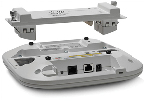
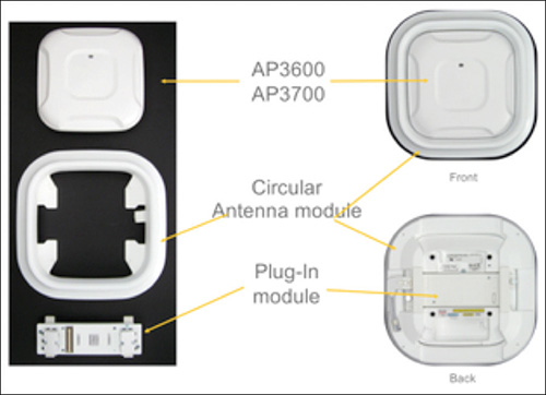
To support “hearing” the same data packet from the same client through multiple access points, FastLocate requires an additional radio. This is expected, because when a client sends a data packet to an access point, it does so for a specific channel and frequency. Another neighboring access point, next to the one the client is communicating with, most likely has its radios on different channels to avoid co-channel interference. So the only option left is to dedicate a third radio to keep monitoring all channels and detect data packets from clients associated to other access points. For such a reason, at the time of this book’s writing and for the CCIE exam blueprint, FastLocate is supported on 3600 and 3700 series access points only, with the addition of the so-called Wireless Security Module (WSM), whose ordering part is AIR-RM3010L-X-K9 (X being the corresponding radio domain code). Such a module is also sometimes called “HyperLocation Module” or “HyperLocation Module with Advanced Security” in some configuration guides, because it is used for hyperlocation too (more on this in the next section). Figure 6-22 shows a preview of the WSM.
Access points tracking clients through FastLocate with this additional radio module need to monitor channels in a synchronized fashion. Monitoring radios from neighboring access points have therefore to synchronize themselves together on the same channel, at the same time, to hear data packets from the same clients. Security modules from different neighboring access points cycle through the same channels at the same time and Network Time Protocol (NTP), already needed for all other location techniques, starts playing an even more fundamental role with FastLocate.
Some further general recommendations include not mixing access points with Probe RSSI and FastLocate, at least not on the same floor, for example, as well as using FastLocate with 3600 and 3700 series access points with internal antennas only. The additional module has omnidirectional antennas, and using it on an access point with external antennas could create incongruences between the coverage area and the location tracking zone.
802.11 Active RFID Tags
Radio frequency identification (RFID) tags are not exactly a technique to calculate location coordinates but rather an alternative to standard wireless clients for assets tracking. In contrast to passive tags, which emit when stimulated by a dedicated tag reader, active RFID tags are battery powered devices of relatively contained dimensions, which can be attached to objects or persons and which keep emitting frames at a specific, regular frequency and optionally with additional information, such as battery level, temperature, emergency button push, and so on. These tags act as kind of wireless clients, in the sense that they actively send frames that are captured by access points and used for trilateration with Probe RSSI: for such a reason we specifically talk about 802.11 active RFID tags as the only type of RFID tags supported for location services with both MSE and CMX. Some tags do send probe requests too, but the most common frame type for location with 802.11 active RFID tags is a Layer 2 multicast frame identifying the tag and containing the aforementioned additional options.
Assets tracking with RFID tags requires you to attach specific devices on objects or persons and configure them. Nevertheless, because of the additional configuration and control you can apply to those tags, such a solution answers the need for actively tracking with a guaranteed frequency and other services. By having more control on the wireless devices’ behavior, you can influence how often they are tracked. The following are some common options you can find among the most popular RFID tags’ solutions:
Choice of channels, where to send multicast frames, so as to reduce the list of radio frequencies in use as the same configured for access points. RFID tags can also send the same frame on all channels of the list at each beaconing period, to make sure all nearby access points hear it on their corresponding frequencies.
Possibility to send frames more frequently only when in motion, to have the best of both power saving and tracking frequency.
Message repetition parameters, not to risk to lose frames, as multicast frames are not acknowledged.
Cisco Compatible eXtensions (CCX) options, to include extra data such as battery level, temperature, emergency button alerting, and so on.
Transmit power and data rates configuration for additional power-saving optimization.
Typical use cases for RFID tags include, for example, carts tracking for medical equipment in hospitals, personnel tracking and rescue for specific industry sectors, and repair parts location for manufacturing customers. These types of deployments often take advantage of the extra data that RFID tags can send through CCX options, such as battery life information or emergency panic button push, to send API northbound notifications from CMX toward external applications.
When deploying RFID tags, you may also be confronted with additional components, called chokepoints or exciters by some vendors. These are devices dedicated to “wake up” RFID tags as they pass nearby and sometime even to reconfigure them. You may encounter scenarios where, when entering a specific zone, the RFID tag parameters need to be changed on-the-fly, maybe to send messages more often, for example, or with a higher transmit power. A dedicated chokepoint could achieve this when RFID tags approach within its range.
Although it dates back to some years ago, a very good and comprehensive reference to have a deep dive on all the RFID tags configuration options is still the “Wi-Fi Location-Based Services 4.1 Design Guide”:
https://www.cisco.com/c/en/us/td/docs/solutions/Enterprise/Mobility/WiFiLBS-DG/wifich6.html
Angle of Arrival (AoA) and Hyperlocation
Sometimes also referred to as Direction of Arrival (DoA), this technique calculates a client’s location by determining the angle of incidence with which the client’s signal arrives at the receiving sensor. This does not necessarily imply that one single access point instead of three or four would be enough to achieve the same location results as with Probe RSSI. The major benefit of AoA, if implemented on all the same access points as if planning for Probe RSSI, would be to increase the location accuracy up to one to three meters for the 50% probability and up to around five meters for the 90% probability. Hyperlocation is the Cisco trademark for angle of arrival, and (always at the time of this book’s writing and for the CCIE exam blueprint) it is a solution based on 3600 or 3700 series access points, with the WSM module, plus an additional circular antenna mounted around the access points, as shown in Figure 6-23.
Hyperlocation reuses the principle of tracking clients based on data packets, hence the need for the same WSM module as for FastLocate, but also supports extra calculations for the angle of arrival thanks to the circular antenna, which uses up to 32 internal receiving elements to determine the angle of incidence of a client’s signal. As for FastLocate, Hyperlocation requires clients to be successfully associated to the Wi-Fi for taking advantage of data packets. A common practice for best results would also be to make sure that access points with their circular antennas have line of sight with clients whenever possible and, to minimize interferences, to privilege SSIDs on 5 GHz frequencies only.
The improvement in accuracy with hyperlocation requires on the other side a higher precision and discipline in configuring the solution, placing the access points on maps, orienting them, and so on. Although you are always dealing with omnidirectional internal antennas, the orientation of the additional circular antenna does play a fundamental role in how precisely you can track clients: its configuration in Prime Infrastructure should reflect the exact physical installation. All such details for configuring hyperlocation are available in the official best practices and troubleshooting guide:
As mentioned, the goal of the Hyperlocation solution is not to deploy fewer access points than with Probe RSSI or FastLocate, but rather to achieve better accuracy. For such a reason, a deployment or a site survey optimized for Probe RSSI is a good starting point to add Hyperlocation on top, by installing the additional WSM modules and circular antennas. However, as opposed to planning for Probe RSSI, where some access points can be in Monitor mode if redundant for coverage, with Hyperlocation access points need to be either in Local or in FlexConnect mode (for centrally switched WLANs only, at the time of this book’s writing). This requirement could lead to co-channel interference, but you can easily avoid such a situation through AP Groups. You can assign access points that shouldn’t serve any SSID to a specific AP Group with no SSID configured, while making sure to configure the wanted SSIDs with a WLAN ID of 17 and higher, and in an AP Group containing all other access points supposed to serve those SSIDs.
Bluetooth Low Energy
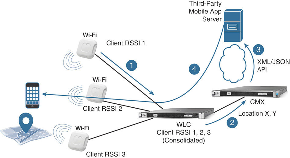
All the aforementioned tracking techniques are based on a wireless infrastructure, where the access points, the wireless LAN controller, and the location engine of CMX are collecting data, aggregating them, and calculating location coordinates. Clients are playing a more “passive” role, while the infrastructure does all the math to calculate (X,Y) coordinates and potentially feed them to third-party applications via APIs. From here, those applications can use (X,Y) coordinates for analytic purposes, or even to offer location services back to those same wireless clients, for wayfinding solutions through mobile apps or websites, for example. A quick visual representation of such a workflow is displayed in Figure 6-24.
Bluetooth Low Energy (BLE) solutions take the opposite approach, with the client now playing a more active role. BLE emitters, sometimes also referred to as beacons (from Apple’s proprietary BLE messages, called iBeacons) or even tags, originally are standalone transmitters that do not interact with one another or with a centralized control system. The main purpose of a BLE emitter is to keep sending the same signal with the same information, more or less like a lighthouse in the middle of the sea. It is the client’s role, through a dedicated mobile application, to hear and collect those messages, like a boat in the sea receiving the beam from the lighthouse. As a consequence, the most important prerequisite for BLE location solutions probably is the fact that clients must have a dedicated application installed to capture and interpret those beacons from BLE emitters.
BLE emitters transmit beacons, or announcements, including the following main fields, as shown in Figure 6-25:
A prefix, usually dedicated to the company’s identifier having manufactured the BLE tag
A universally unique identifier (UUID) that you can configure to reflect a main location, or even your company’s name, for example
A major value, which you can use to indicate a first level of location (campus, building, floor, etc.)
A minor value, which you can use to indicate a second level of location (floor area, zone, room, etc.)
A field for the transmit power that can be used to determine the distance of the client from the BLE emitter
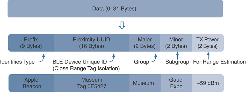
Figure 6-25 BLE Announcement Format
Mobile devices with a dedicated application (integrating the SDK from the company having manufactured the BLE emitters, to correctly interpret BLE announcements) capture those BLE messages and then usually relay their information upstream, to an application server or similar having the necessary horsepower for additional calculations. The application server, based on the information from all the messages captured by and received from the mobile device, can then implement algorithms to determine the mobile device’s location or to derive other services. At the stage where the beacons’ information arrived from the client to the application server, we are in a similar situation as with CMX and wireless location, where the (X,Y) coordinate can be calculated by the location server and reused for additional services too. The main difference with respect to wireless location techniques is that the mobile device plays the role of collecting the information and then relaying it to an application (or location) server upstream that takes advantage of those data. This kind of workflow is represented in Figure 6-26.
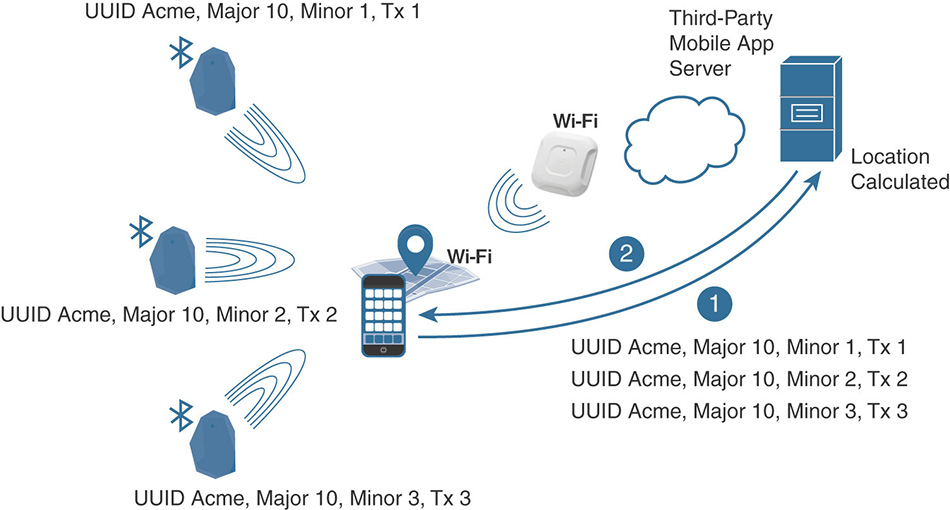
Technically, you could support location services purely through BLE beacons while providing basic data connectivity to mobile devices even through 4G, for example, so not necessarily Wi-Fi. However, BLE emitters are usually powered by batteries, which you would need to change every 3–5 years. By their nature of “beacons,” the vast majority of BLE emitters on the market, even if from the same vendor and part of the same solution, do not synchronize among them and do not communicate with a centralized management system either: to configure them, you usually need to use a dedicated management application running on a mobile device and to approach each emitter one by one. Despite the lower cost of a BLE emitter compared to a wireless access point, all these additional requirements might cause the overall cost of the location solution to rise higher with BLE than with Wi-Fi. As shown in Figure 6-27, one common approach is to mix Wi-Fi and BLE location: you could use the WLAN infrastructure to locate clients with a higher error margin in those areas, where just a few meters of precision are enough for the end customer’s needs; in other zones with less than one meter proximity needs, you could then deploy BLE to fine tune the accuracy. A typical example of such a mix could be wayfinding services inside an office or reservation options when approaching or entering meeting rooms.
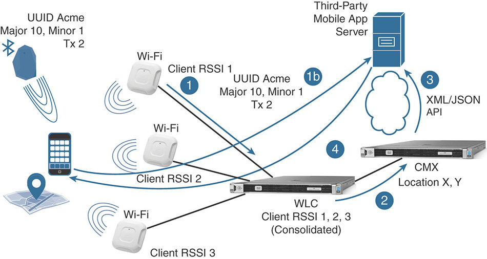
With a mix of wireless location services provided by CMX and BLE location supported through an external third-party server, you should be aware that there will be two distinct data sources for (X,Y) coordinates: CMX and the third-party server for BLE. CMX does not support location through BLE emitters. Thanks to CleanAir and interferers location, CMX can display the position of BLE emitters on a map, where you can flag them as active, missing, rogue, and so on, and even configure API notifications if their state changes (for example, if they are not heard through CleanAir anymore or if they get misplaced). However, CMX supports wireless location techniques only, and even if we theoretically could make people wear BLE emitters and try to track them as we would do for RFID tags, this is neither a recommended nor a supported scenario as of today.
Management Access
When installing CMX, you need to configure at least two accounts: cmxadmin for command line and upgrade operations, and admin for accessing the graphical user interface with full rights for any operation. You can create more accounts in the local database with differentiated privileges for accessing the different GUI’s tabs, as shown in Figure 6-28. Under the menu MANAGE > Users you can add new users and define whether they will have full read and write access to one or more tabs of the GUI, or just general read access. If you configure a user with the Read Only role, that account cannot be assigned with any other role; otherwise, it would start having write privileges too.
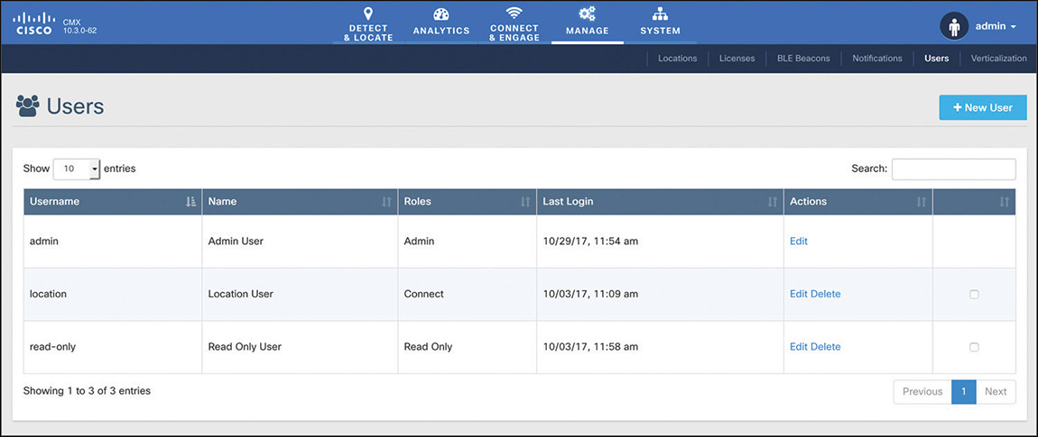
It is important to note that access to a specific tab also determines access to the corresponding APIs for features under that tab. For example, an account with the Location role, having read and write access to the DETECT & LOCATE tab, will have access to the APIs for location, too, and for location only (that is, under the /api/location calls).
On top of GUI access, configuring different users is commonly used to provide differentiated access to external applications, which should query different services of CMX via APIs.
Besides different user roles that you can configure through the GUI, you should be aware of command-line options to reset the main admin account for the GUI. By connecting via console/SSH to CMX through the cmxadmin account (configured during the installation process), you can use the command cmxctl users passwd admin to reset the admin account’s password. Through the same command, but for the monitor account, you can also reset the password for the default read-only user role. The full details on the use of these commands and others are available in the “Cisco CMX Command Reference Guide, Release 10.3 and Later”:
Network Services
CMX provides three main services, through which others could be derived too. The main and most deployed one is the location services that have been inherited from the former MSE and Location Appliance solutions. By working with the calculated location data, CMX also provides the analytics service for additional statistics. Connect and engage on the other side designates an additional set of options for guest portals.
Some configuration guides or release notes might also often refer to CMX services as Detect, Connect, and Engage. Detect designates the presence and location tracking capabilities, Connect indicates the guest portal services, and Engage represents the API options to feed external third-party solutions, such as mobile application servers to engage with end users. It should be clear that CMX does not support features to “wake up” mobile applications or send SMS and interact with end users. CMX provides a database that other applications can take advantage of via APIs, to then communicate with mobile devices and end users according to data retrieved through those APIs. APIs for location services in particular also support the so-called northbound notifications: these are push messages, in either JSON or XML format, sent on-the-fly as soon as the event for which they are configured is triggered.
Note
The full specifications on all the supported API calls are available through any CMX installation by browsing to https://CMX_IP/apidocs/ and selecting the corresponding service (for example, Location, Analytics, Presence). To try out API calls directly from these CMX menus you will need to enter a username and password with the right API access privileges.
Different services in CMX 10.3 consume different levels of licenses. Location and Connect services, with all the corresponding APIs, consume a Base license for every access point, from where clients are located or authenticated through guest portals. The Analytics service and its APIs require an Advanced license per access point contributing to location calculations, whose data is then used for the analytics reports.
Location
We described different location techniques throughout the previous paragraphs: their level of accuracy will determine the precision of coordinates calculated by CMX. One major distinction you may need to make about location is the difference between presence (that is, cell of origin) and all other techniques.
Presence supports statistics based on whether a client’s MAC address is seen or not, with which RSSI, for how long, how often, and so on. During the initial installation, CMX asks you to choose between a Location and a Presence mode. As also shown in Figure 6-29, the CMX Presence installation primarily gives access to one main tab called PRESENCE ANALYTICS, which displays three types of statistics: counters for the number of visitors, passerby and connected users, their dwell times, and their distribution with respect to repeated visits. A single access point registered to a WLC (in the Mobility Express model too) is technically enough for presence to work; because there is no notion of placing clients on a map, Prime Infrastructure is not part of this workflow. Controllers in CMX Presence can be added through the SYSTEM tab by clicking the Settings button and by specifying the controller’s SNMP credentials.
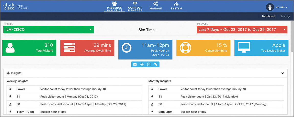
Presence supports grouping access points into sites: this is a local option on CMX itself that does not affect potential AP Groups or FlexConnect Groups already configured on the WLC, if any.
You can think of graphs and numbers reported by CMX Presence as trends of how crowded a specific site could get: they do not expose information on specific MAC addresses and cannot be used as precise counters for visitors, for example, because there is not necessarily a one-to-one mapping in real life between a wireless device and a person. If needed, through APIs you can still access raw data of MAC addresses from active clients, for example.
As for a typical CMX Location installation, CMX Presence also supports the same CONNECT & ENGAGE services (more on this later).
The CMX Location installation type is the one you need to be most familiar with for the Wireless CCIE exam and probably the one end customers will need to deploy more often. This installation mode provides access to a dedicated tab for DETECT & LOCATE, where wireless clients can be displayed on maps, as well as to an ANALYTICS tab displaying statistics derived from location coordinates.
For location services to work, you must import maps in CMX. These maps come directly from Prime Infrastructure, and correct AP placements and orientations become fundamental for location accuracy. For importing maps to CMX you have several options:
Through the CMX graphical interface, under the SYSTEM tab, click the Settings button and browsing to Controllers and Maps Setup > Import. From here you can specify credentials for CMX to connect to Prime Infrastructure directly and pull all the maps and WLC coordinates.
This option will import all maps and all controllers from Prime Infrastructure to CMX. Although you can still delete unneeded plans and WLCs afterward, you may probably want to import only specific ones.
Prime Infrastructure 3.2 supports an option to push maps to CMX after having added CMX itself to Prime Infrastructure. You can find this under Services > Mobility Services > Connected Mobile Experiences by selecting an already added CMX server from the list and clicking Import Map to CMX. This method allows selecting specific maps only.
The third option, which is also the one preferred by the authors of this book, is to manually export maps from Prime Infrastructure in a .tar.gz compressed file and then import that very same file in CMX.
You can export maps from Prime Infrastructure under Maps > Wireless Maps > Site Maps (New!) by clicking Export > Map Archive on the top-right option of the page. From the right side panel you can select the exact floors you would like to export, and then click Generate Map Archive to download the needed file, as shown in Figure 6-30.
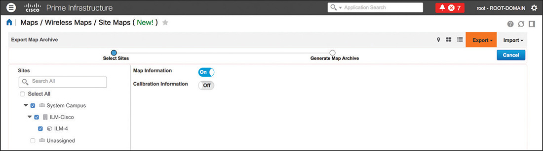
Figure 6-30 Example of Maps Exporting from Prime Infrastructure Back in CMX, you can import the map file under the SYSTEM tab by clicking the Settings button and browsing to Controllers and Maps Setup > Advanced: here you’ll find an option to import maps through the file generated from Prime Infrastructure.
Although it could take a few more seconds than the other two options, adding controllers and maps in a manual fashion in CMX usually allows a bit more visibility on exactly which maps to import and also allows some easier troubleshooting if something accidentally fails in the process.
Under the same Advanced settings for importing the maps file in CMX, you can also find all the fields to point CMX to the controller(s). Along with the manual maps import process, this should be the preferred approach to declare controllers too.
A WLC is added in CMX by specifying its SNMP credentials. These are needed for CMX to go and configure the WLC directly, with all the required settings for the Self-Signed Certificate (SSC) key hash (more on this later in the NMSP section).
Note
When a controller is configured to send data to CMX, it does so for all its access points; however, this does not mean that CMX is consuming licenses for all those access points. License consumption for location and other services is based on the access points on the maps, through which CMX is supposed to track clients, interferers, and so on.
For example, if a WLC has 100 access points registered but CMX has a map with only 50 of those access points positioned, the CMX license consumption will be of 50 access points, despite the fact that the WLC is sending data for all 100 access points. As of today there is no direct option to select which access points contribute to location calculations and consume licenses: the main technique to filter out access points is to import a map with just the wanted access points in it.
After configuring maps and controllers in CMX, you should start seeing clients, interferers (BLE emitters included), and RFID tags being tracked. You can select exactly which categories among these three to track under the SYSTEM tab, by clicking the Settings button and the Tracking option.
Under the same Settings menu, the Filtering options let you modify some general parameters to include or exclude specific data.
The Duty Cycle Cutoff specifies the duty cycle percentage, for which CMX should not track interferers: the default value of 0 means that CMX will track all interferers.
The RSSI Cutoff for probing clients determines with which dBm value CMX starts discarding RSSI values if three or more values with a higher RSSI are already available for location calculations. For example, if you configure the RSSI Cutoff at −85 dBm and CMX receives measurements of −47 dBm, −68 dBm, and −93 dBm for the same client from three different access points, it still uses the one at −93 dBm. For the same RSSI Cutoff configuration, if CMX receives measurements of −47 dBm, −68 dBm, −76 dBm, −89 dBm, and −93 dBm for the same client, it discards those at −89 dBm and −93 dBm because it already has three usable ones above the configured cutoff limit of −85 dBm. Other Filtering parameters are probably self-explanatory, but it is worth mentioning the option Enable Locally Administered MAC Filtering, which is checked by default. Thanks to this setting, CMX discards all random and temporary MAC addresses self-assigned by some client vendors while probing, using the specific bit set to identify them as locally administered, which we discussed in the previous section when describing Probe RSSI and FastLocate tracking techniques.
Among other settings, you should probably be aware of options in the Location Setup menu. Although you should usually leave these configured as is by default, it might help knowing some of their main behaviors and goals:
Enable OW (Outer Walls) Location is an ancient inheritance from the former MSE and Location Appliance solutions, which is not being used by CMX anymore but was left there for some backward compatibility corner cases. Its purpose was to take into account walls with attenuations higher than 13 dB, if configured on maps.
Location calculations do not take into account obstacles and their attenuations as configured through the map editor in Prime Infrastructure.
Enable Location Filtering, checked by default, is used to take into account previous location calculations to determine the next one. The direct effect of such an option is to avoid a client “jumping” too far apart between one coordinate and the next.
Use Default Heatmaps for Non Cisco Antennas is rarely checked and has the effect of letting CMX use best effort location calculation models even when not using Cisco antennas on your access points, which is not recommended anyway.
Chokepoint Usage, also enabled by default, lets CMX accept information on the closest chokepoint, as communicated through CCX options, if supported, by RFID tags.
Enable Hyperlocation is an option checked by default that stays hidden for standard and low-end virtual machine installations. Only if CMX is running as a high-end virtual machine or on a physical 3365 appliance is this setting exposed in the GUI.
Optimize Latency causes CMX to use less data for location calculations and speed up computations. This is achieved, for example, by setting relative discard RSSI and AoA times (more on these in the next bullet points) to 30 minutes. Because accuracy might decrease, you should consider this setting only if recommended by the Cisco technical support.
Use Chokepoints for Interfloor Conflicts gives you the choice of when to use a chokepoint’s information in CCX options from RFID tags to locate CCX compatible RFID tags. NEVER means that chokepoint’s information is never used if similar locations are calculated between different floors. ALWAYS lets CMX always use a chokepoint’s information in location calculations, independently on whether there could be an inter floor conflict. FLOOR AMBIGUITY causes CMX to give higher priority to chokepoint’s information to resolve conflicts if similar locations are calculated between different floors.
Chokepoint Out of Range Timeout determines the time in seconds after which the latest chokepoint’s information is not considered anymore when an RFID tag leaves that chokepoint’s coverage zone (for example, the chokepoint’s information is not reported anymore through CCX options). When a chokepoint’s information is not used anymore, CMX goes back to using trilateration based on multicast Layer 2 frames’ RSSI.
Relative discard RSSI time is the timeout in minutes from the latest RSSI measurement after which older RSSI measurements should be discarded. For example, if this time is set to 3 minutes, CMX discards measurements that are more than 3 minutes older than the latest RSSI measurement.
Relative discard AoA time is the same timeout as the previous one, but for AoA measurements instead of RSSI ones.
Absolute discard RSSI time is the timeout in minutes from the current time on the CMX clock after which older RSSI measurements should be discarded. For example, if this time is set to 3 minutes, CMX discards measurements that are older than 3 minutes compared to CMX’s current time.
RSSI Cutoff has the same effect as of the RSSI cutoff under the Filtering menu, but this one in particular is dedicated to the RSSI of data packets.
Individual RSSI change threshold is a parameter that, along with the next three in this list, allows CMX to determine whether a significant wireless client’s movement took place, so that previous sets of RSSI measurements should be discarded to recalculate location with new ones. If any value between individual or aggregated RSSI changes is met, CMX will discard previous sets of RSSI measurements and use only new ones for location recalculations. Individual is for a single RSSI measurement change.
You should never change this option or any of the three following ones except under guidance from the Cisco technical support.
Aggregated RSSI change threshold is for RSSI changes within a fixed aggregation window, internal to CMX, and its purpose is very close to the previous threshold.
Many new RSSI change percentage threshold also triggers a location recalculation by discarding older RSSI measurements, but only if one of the previous two parameters didn’t trigger it already, and only if the missing RSSI percentage is met too. This threshold indicates the percentage of new RSSI changes in the aggregated location data from the WLC.
Many missing RSSI percentage threshold triggers a location recalculation after the specified percentage of missing RSSI information only if the new RSSI change percentage is also met.
History Pruning Interval specifies the number of days during which to retain location data in CMX’s database.
Although not mandatory for CMX to start calculating (X,Y) coordinates, as a further step for your location setup you may want to configure inclusion and exclusion regions on maps, as well as zones.
You can also create inclusion and exclusion regions from Prime Infrastructure through the map editing options. If you import a map from Prime Infrastructure into CMX without any inclusion region, CMX automatically creates one global inclusion region corresponding to the whole floor area. An inclusion region defines the area of a floor within which all wireless clients should be located. If without an inclusion region, wireless clients are supposed to be located outside of such an area, with the inclusion region they will be “snapped” inside or at its boundaries. An exclusion region works the opposite of an inclusion one: it is an area where wireless clients should not physically be located in real life. Devices that without an exclusion region are supposed to be located within its specific area, with an exclusion region will be “snapped” on its boundaries. When creating inclusion or exclusion regions, you may need to wait a few location calculation cycles before seeing clients respectively outside or inside those regions starting to be “snapped” on their boundaries or further away. In CMX you can configure exclusion, inclusion regions, and zones under MANAGE > Locations. From the left side panel you can browse to the needed floor and then click the arrow on the top-right corner of the icon from the list, saying Go to Map View: from here, you can access a dedicated editor to add, delete, and modify those areas, as shown in Figure 6-31.
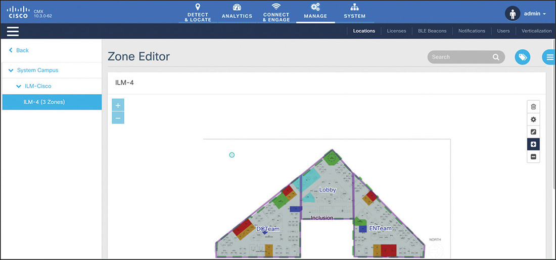
Zones are also areas that you can draw on maps in CMX from the same editor, but they have very different roles from inclusion and exclusion regions. Zones do not contribute to location calculations; their names are included in API notifications, and this could be useful information for external applications working with statistics on general areas rather than precise coordinates. The other main utility for zones is for analytics reports.
When location services are up and running, a common use case is to export coordinates to external applications through APIs and northbound notifications. You can configure notifications in particular under MANAGE > Notifications; by setting the type of notification and its conditions you specify the event triggering CMX to send JSON or XML messages to external solutions. A typical example is for CMX to send a notification every time the location of a device changes further away than X feet: triggering messages after a movement of a specific distance is a less overwhelming option for external applications than sending notifications for every single location update.
Analytics
The CMX name and services originated from the acquisition of the ThinkSmart company taking advantage of location coordinates via APIs to provide analytics statistics and reports, and today we could say that the Analytics features in CMX are the strongest legacy from that specific acquisition. By working with raw (X,Y) coordinates and correlating them based on time, number, and frequency of visits, as well as other criteria, CMX provides reports with widgets spanning from basic wireless client counters to more advanced path analysis. A report is technically a page with widgets that you can choose from a list; you can create multiple reports with different widgets, or even with the same widgets but different time ranges, for example. As anticipated in the previous section, zones can be used in reports and widgets to compare data between different areas on floor plans: these could be simple visitor count distributions between areas or, for example, users’ paths analysis starting from a specific zone and ending in different ones.
CMX supports the following widgets to include in an Analytics report, some of which are also shown in Figure 6-32:
Visitors provides you with device counters, which you can organize by time of the day, areas, or by displaying overall daily counters. For this last type of statistics, a visit is defined as the appearance of a device in a single area and on a single day, from 00:00 to 23:59.
If you try to edit a Visitors widget through the icon on its top-right corner, you can display what is called a Summary view. On top of the overall counter for total daily visits, CMX also shows the percentage of new versus repeated visits. A repeat visit is defined as a device having already been in that area within the last six months.
Wi-Fi Adoption, although it is a separate widget, goes along with the previous one for showing associated versus probing visitors and gives a useful indicator of how many clients are actually connecting to and using the wireless network. This widget won’t have too much sense if in the System’s Filtering settings you check the option Exclude Probing Only Clients.
Dwell Time widgets show the duration of visits over the time period that you specify. The dwell time for a specific device is calculated as the sum of all of that device’s visit durations to a specific area.
Dwell Time Breakdown is another widget end users often tend to include in reports with other Dwell Time graphs and displays the distributions of number of visits based on different durations.
Correlation enables you to visualize, starting from a so-called focus area, how many devices seen in that area were seen in other areas too. Focus areas can be campuses, buildings, floors, or zones. Configuring zones through the map editor is therefore needed for Correlation widgets, which take advantage of such areas defined on maps to calculate and display counters for Wi-Fi devices in a specific zone and to then correlate them to other zones.
Path is kind of an evolution of the Correlation widget. As for Correlation, you start by choosing a focus area, and CMX automatically generates a graph displaying how many visitors from that area came from other areas and went to other areas too.
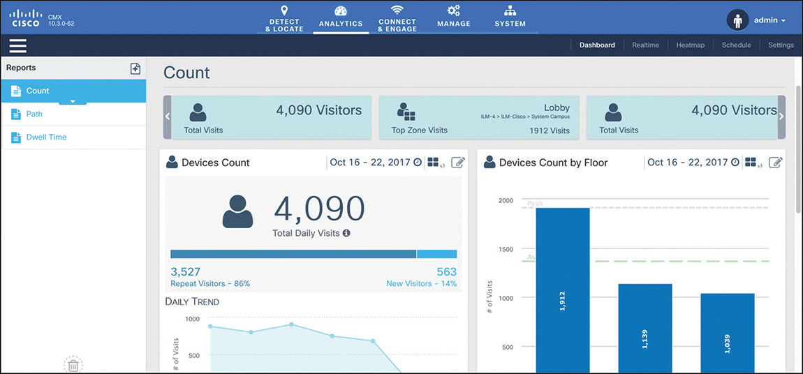
Figure 6-32 Example of Widgets in Analytics Reports
You can find well-detailed explanations of all the Analytics parameters and their uses directly on your CMX by browsing to the following URL:
https://CMX_IP/docs/pdf/analytics-doc.pdf
The shortest period of time supported by reports from the main analytics dashboard is for the current day. However, you also have access to a dedicated real-time report under the Realtime option of the same ANALYTICS tab, from where you have access to a Wi-Fi Adoption and a Device Counts widget that are continuously updated.
Other features of the analytics engine include a Heatmap menu, which shows concentration of wireless clients on floors, either real-time or by playing it back in history. Colors of a heatmap here are not directly related to specific counters but simply display higher or lower concentrations of wireless devices.
Although all these analytics options are available with the CMX Location installation mode, you could still take advantage of them for presence use cases too. For example, if you generate visitors’ counts or dwell times for entire buildings, you don’t necessarily need precise location coordinates on floors for those statistics to still provide realistic trends. The first four widget types from the aforementioned list are probably more intuitive to use for this kind of presence analytics, but you can use Correlation and Path too by configuring buildings or campuses as focus areas, in which case accurate location again might not play a fundamental role.
Note
You may need to use extra caution with your potential end customers when setting expectations about using CMX Location for presence use cases. Because of maps and the interface to locate clients, end users and business teams might start using the DETECT & LOCATE options, even if with inaccurate (X,Y) coordinates, or generate analytics reports based on zones on floors instead of whole buildings and campuses.
Another common technique for implementing analytics is through an external third-party solution. In such a case you could, for example, configure API northbound notifications for location, as described at the end of the previous section, toward an external database, which will store (X,Y) coordinates and any other additional data. A dedicated external solution could then reuse that data to compute analytics reports on client counts, dwell times, correlations, and so on. The advantage of such an option is that reports can be completely customized, even though you might need to take into account some additional costs for the external solution.
The approach we just described is something you may encounter more often than expected: many third-party solutions on the market provide analytics services and support integration with Cisco CMX. The technical secret sauce used in the background is precisely to configure location northbound notifications, and then let the third-party solution implement custom analytics and other tasks.
Connect and Engage
Guest portal options on CMX are not dependent on location or analytics services or vice versa, but they provide additional tools to connect end users and potentially increase location accuracy if using more advanced techniques such as FastLocate or Hyperlocation. In your daily job as a wireless expert you may be confronted with the decision of which guest solution to deploy between portals on the WLC, CMX Connect, and Identity Services Engine (ISE). Although not strictly related to the Wireless CCIE exam, it might be useful to clarify the main advantages and use cases for each of the three:
The WLC’s internal portal is usually ideal for so-called hotspot scenarios, meaning when visitors should need to validate an Acceptable Use Policy (AUP), for example, by checking a box for terms and conditions on the landing portal to then get directly authorized on the guest network.
CMX Connect is generally recommended for the very same hotspot use case as the previous solution. However, with respect to the WLC’s internal portal, CMX offers much easier and more advanced customization features for portals, along with options for redirecting to different pages based on the client’s location and for integrating with social networks.
ISE is probably the most complete solution, allowing support for the same hotspot needs as the other two, as well as other use cases, such as sponsored portals (for example, where visitors are asked for credentials generated by a “sponsor”) or self-registration (for example, visitors generating their own credentials from the guest portal).
Figure 6-33 shows a quick positioning of the three main Cisco guest solutions (WLC, CMX, and ISE).
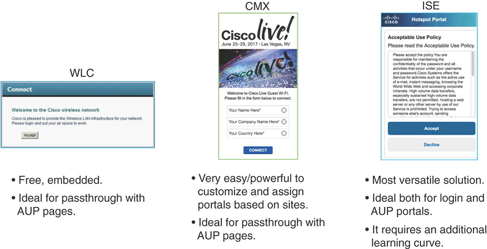
CMX Connect is based on the Local Web Authentication (LWA) technique, as shown in Figure 6-34. The term “local” comes from the fact that a guest portal’s URL (for example, CMX’s guest services’ URL) for redirection is locally configured on the WLC, under the Layer 3 security settings of the WLAN. More specifically, the WLAN on the WLC needs to be configured with the Passthrough option. The full web authentication process is detailed as follows:
The WLAN is configured for an open or PSK-based SSID, with a Layer 3 web policy security for passthrough, a preauthentication ACL, and an external web redirection to the CMX URL: https://<CMX_IP>/visitor/login.
The preauthentication ACL should permit HTTPS traffic from wireless clients to CMX and vice versa. Also, although DHCP and DNS are now implicitly allowed in WLANs with web authentication configured, we generally recommend explicitly defining permit rules for these services in the preauthentication ACL. Doing so allows better visibility for troubleshooting, because you could verify through the ACL’s counters whether DHCP and DNS traffic are correctly allowed. Other HTTP resources, except probably some specific ones for internal needs or advertisements, should usually not be allowed in the preauthentication ACL and should be denied by the default deny statement.
When a client connects, it obtains an IP address via DHCP, as permitted by the preauthentication ACL. When the end user then opens a web browser to access an HTTP resource denied by the preauthentication ACL, the WLC will redirect the user to the CMX URL configured locally under the Layer 3 security options of the WLAN. The CMX URL should not cause any further redirection because it is permitted in the preauthentication ACL.
Mobile devices nowadays often implement web portal discovery techniques and pop up a web browser automatically to get the end user redirected to the guest portal without the need for manually accessing a specific HTTP resource over a typical web browser. With Apple devices, for example, such a technique is called Captive Network Assistant (CNA): the device automatically tries to reach external URLs, such as http://www.apple.com/library/test/success.html, and, in case of redirection, it automatically pops up an embedded browser to prevent the end user from having to launch a browser and trying to explicitly access an HTTP destination. The WLC supports an option to bypass such an automatic redirection, which is called Captive Portal Bypass, disabled by default, which can be activated through the following command line (on a global level, for all WLANs, and needing a WLC’s reboot to be applied):
config network web-auth captive-bypass enable
With this option enabled, the WLC replies with an HTTP OK to devices’ requests for external URLs on apple.com, hence not triggering the minibrowser automatic pop-up. For a better end user’s experience, you may want to leave such an option disabled by default.
Another default option we tend to recommend leaving disabled is the support for HTTPS redirection. With such a feature the WLC could redirect end users even when the initially requested external website is via HTTPS. Because of the nature of SSL, it is not possible to avoid a certificate warning (the HTTPS session is kind of “hijacked” by the WLC to achieve this), and activating such a function is not optimal for the WLC’s performance either. As a further note, you should keep in mind that because the CMX URL for the guest portal services is in HTTPS, end users will see a certificate acceptance warning, because by default the CMX’s certificate is a self-signed one. To upload a certificate signed by an external authority, refer to the “Getting Started” chapter in the official “Cisco CMX Configuration Guide, Release 10.3 and Later”:
Alternatively, you might also disable the SSL mode on CMX through the following command, to support redirection via HTTP (and modify the WLC’s preauthentication ACL and redirect URL accordingly):
cmxctl node sslmode disable
The WLC redirects the end user to the CMX URL by postponing additional information regarding the client’s MAC, the AP’s MAC, the SSID name, and so on. It also includes a “switch_url” variable containing an HTTPS pointer to the virtual interface of the WLC itself. This is an instruction to tell CMX to redirect the client back to the virtual interface at the end of the process. The full redirection URL from the WLC looks like the following:
https://<CMX_IP>/visitor/login?switch_url=https://<VIRTUAL_IF>/login.html&ap_mac=<AP_MAC>&client_mac=<CLIENT_MAC>&wlan=<SSID_NAME>
The end user at this point lands on the CMX Connect guest portal and needs to complete some tasks. These could range from a basic acceptance of terms and conditions, to an authentication through a code received by SMS, to a login through social networks, and so on. After completing tasks on the portal, CMX redirects the user back to the WLC’s virtual interface to signal the WLC that the client should be successfully authorized on the WLAN. The redirection URL from CMX is similar to the following:
https://<VIRTUAL_IF>/login.html?button-Clicked=4&err_flag=0&redirect_url= http://www.cisco.com
The client here requests a page on the WLC’s virtual interface via HTTPS, so you might need to anticipate a second SSL certificate warning if the virtual interface’s certificate is a self-signed one or is signed by an unknown authority. The most common option would be to generate and install a virtual interface’s certificate signed by a known authority or, even if less recommended, you could also disable HTTPS for Layer 3 Web policies on the WLC itself with the option WebAuth SecureWeb under MANAGEMENT > HTTP-HTTPS.
It is important to note that CMX redirects the client to the WLC’s virtual interface by postponing the option button-Clicked=4: this is what tells the WLC that everything is fine for passthrough and that the client should be authorized. No further authentication is needed from the WLC to the local guest database or an external RADIUS server, for example, as we would implement for a WLAN configured with standard web authentication (for example, a guest portal asking for login and password).
Because the WLAN on the WLC is configured for web passthrough, the WLC does not perform any kind of validation on the client. It just waits for CMX to redirect the client with the option button-Clicked=4 postponed. CMX’s redirection to the WLC’s virtual interface is triggered by CMX when the client completes whatever actions you require on the guest portal on CMX. For example, if you configure a portal with a terms and conditions box to check before connecting, then checking that box and clicking Continue triggers the CMX’s redirection to the WLC’s virtual interface with the button-Clicked=4 option. If you configure a portal with an SMS code to enter, after entering that code and clicking Continue, CMX triggers the final redirection to the WLC’s virtual interface.
Because the WLC does not perform any authentication for the client, there is no notion of dynamic policies assignment either, as we could have for web authentications, where a RADIUS server could send back attributes for ACLs, QoS policies, AVC profiles, and so on. It is important to remember that guest access with CMX Connect does not support per-user policies (very few exceptions discussed later in this section may apply).
After receiving the final HTTP(S) request for its virtual interface with the button-Clicked=4 option postponed, the WLC moves the client to the RUN state and, if configured, applies locally configured static WLAN policies, such as ACLs, QoS profiles, AVC profiles, and so on.
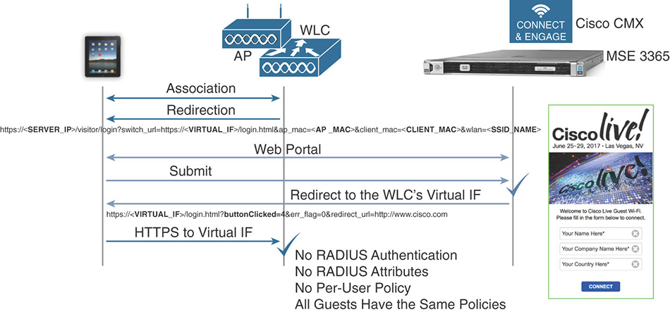
Figure 6-34 LWA for Web Passthrough with CMX Connect
When creating a new portal in CMX under CONNECT & ENGAGE > Library > Portals, you can choose between some templates already proposing different connection techniques, or you can customize your own portal with your preferred elements and connection options. Among the connection and authentication approaches, we can distinguish the following:
Acceptance of terms and conditions and then a Submit button. This is probably the easiest and most effective option, and it should also be the preferred one to deploy CMX Connect.
Registration form, whose fields (for example, Name, Email, Country) can be flagged as mandatory. This option adds some statistical possibilities from data that users enter in the registration form: those data cannot be verified against specific sources or databases, so they may be prone to random content injection.
SMS form by asking to fill in a phone number for sending an authentication code. This technique provides an additional level of security compared to the previous two and is supported with the Twilio SMS platform.
Social login or Facebook Wi-Fi allows administrators to “delegate” login credentials to social networks, as well as to integrate additional marketing tools. For the example of Facebook Wi-Fi, after the end user is redirected by the WLC to CMX, CMX itself redirects to the Facebook login page by postponing the instruction to switch back to CMX after completing the needed login steps through Facebook. The Facebook portal then redirects the user back to CMX by including a token, which CMX verifies against Facebook. If the token is valid, only at that point does CMX redirect back to the WLC’s virtual interface. Even though almost all is transparent to the end user, we could count three redirections running in the background with such an approach, as shown in Figure 6-35.
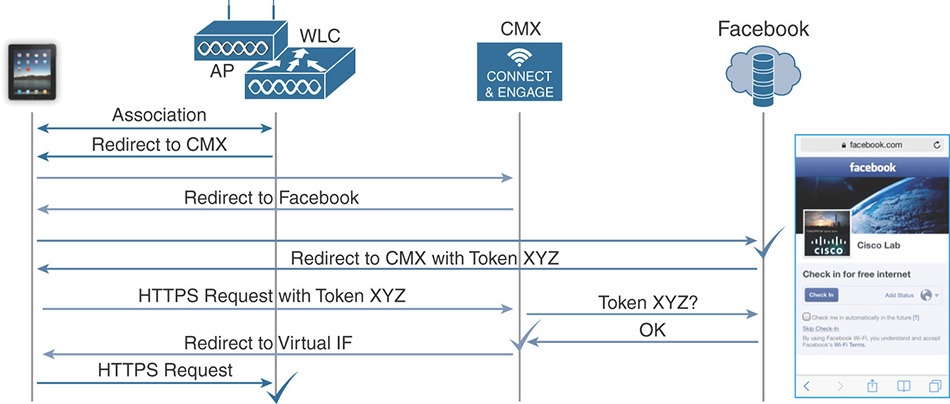
Figure 6-35 CMX Connect Workflow for Facebook Wi-Fi Even if outside the scope of the Wireless CCIE exam, it is worth mentioning that the CMX Cloud supports two additional options for authenticating guest users: vouchers and email delivery. Vouchers are codes that can be generated through the CMX interface and delivered via email or printed directly. Similar to the SMS form, CMX Cloud also supports a field for end users to ask directly a voucher from the guest portal, for it to be delivered via email.
While on the WLC you always configure the same local URL for redirecting to CMX, end users are actually presented (by CMX) with one portal or another based on their location. Under CONNECT & ENGAGE > Connect Experiences you can assign portals to different locations, at a campus, building, floor or even zone level.
One further option you should be aware of in CMX Connect is the support for Property Management System (PMS) solutions and policy plans. Under certain assumptions, this could be the one exception to the previous statement in this section about the fact that with CMX Connect you cannot implement per-user dynamic policies. PMS solutions are often used in hospitality environments, for example, to manage rooms and services associated with their guests. CMX supports a connector to these external solutions allowing embedding PMS options in guest portals. It also integrates so-called policy plans, which are rate limiting policies.
For policy plans to be supported, the configuration on the WLC should be slightly different than what we saw so far for web passthrough. Instead of web passthrough, you should configure the Layer 2 security option for MAC Filtering and the Layer 3 security option for web policy On MAC Filter Failure. Also, under the AAA Servers tab, you should point the WLAN to CMX as a RADIUS server. The behavior now is for the WLC to attempt authenticating clients through their MAC addresses first, then to fall back to web authentication if that fails. When a client’s MAC is authenticated against CMX during the initial connection, CMX is still not aware of that MAC address, so that authentication fails and the WLC redirects the client to the guest portal on CMX. On the portal the client completes the needed actions, CMX redirects it to the WLC’s virtual interface to be put into the RUN state. At this point the requirement would be for the client to manually reconnect, so that the WLC can trigger a new MAC address authentication against CMX, which succeeds because CMX now already saw that MAC address. We should clarify at this stage that a configuration step on CMX requires activating a FreeRadius server integrated into CMX itself, precisely to authenticate MAC addresses. As a final result of the MAC address authentication, CMX acting as a RADIUS server passes back to the WLC the corresponding attributes to affect rate limiting for that client’s session.
Although this could be seen as some kind of technique to dynamically assign bandwidth contracts, it might reveal itself not fully usable in the most common use cases because it requires the client to manually reconnect so that a second MAC address authentication can trigger dynamic bandwidth contracts assignment via RADIUS attributes from CMX.
If needed, the full configuration details for such a specific use case can be found in the dedicated chapter for CMX Connect and Engage of the official “Cisco CMX Configuration Guide, Release 10.3 and Later”:
CleanAir
You can implement interferences detection and mitigation through the WLC and access points supporting the Cisco CleanAir technology. MSE and CMX add on top location tracking, statistics, and history reports for such interferences. The location technique is based on trilateration for interferers’ signal strength, similar to Probe RSSI in terms of accuracy levels. We mentioned both MSE and CMX because at the moment of this book’s writing there still are some functional differences in interferences tracking between MSE 8.0 and CMX 10:
Both MSE and CMX support locating interferers on maps, and both solutions report (X,Y) coordinates to Prime Infrastructure for interferences and zones of impact to be displayed on maps.
With MSE 8.0 you can integrate interferers information in Prime Infrastructure for client reports and troubleshooting, as well as for CleanAir widgets under Dashboard > Wireless > CleanAir, for example. Figure 6-36 shows an example of these widgets with Air Quality data already available without the need for MSE or CMX.
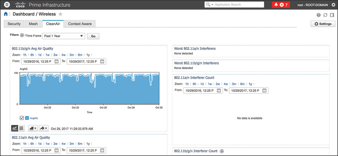
Figure 6-36 Example of CleanAir Widgets in Prime Infrastructure Without Any MSE or CMX With CMX 10.3 or earlier you cannot integrate interferers information in client reports and troubleshooting, and not in CleanAir widgets either. However, you can still view CleanAir widgets in Prime Infrastructure for air quality statistics, because those data do not require MSE or CMX to be displayed. It is not unlikely that future versions of Prime Infrastructure and CMX could support these types of information, as with MSE 8.0 today.
Interferences detection plays an important role for BLE beacons location and management too. Although CMX has dedicated options and menus to manage BLE emitters on maps, information on beacons are based on the whole CleanAir solution. Access points classify BLE beacons as such, and pass data to the WLC always as part of “standard” CleanAir operations, which in turn push the information to CMX. It is CMX that uses these specific data from CleanAir for dedicated features, separating BLE beacons from typical interferers.
Wireless Intrusion Prevention System
Wireless Intrusion Prevention System (WIPS) generally refers to the set of features for detecting and, when possible, mitigating attacks on wireless networks. The acronym is sometimes used to designate different solutions, depending on the available components. For the sake of precision, we should first clarify the real terminology in Cisco Unified Wireless Networks:
Intrusion Detection System (IDS) represents the native set of options on a WLC, which allows detecting attacks based on a list of 17 pre-canned signatures. Custom signatures are supported too, although they are very rarely implemented. On top of being already included in the WLC’s features, the main advantage of IDS is that it enables an already good level of security by supporting detection for the most common types of attacks. For these attacks you can configure SNMP traps on the WLC, as well as the corresponding alarms on Prime Infrastructure; IDS does not support any prevention or mitigation feature.
It is important to keep in mind that the WLC alone supports some prevention and mitigation techniques using specific features, such as Rogue AP containment (manual or autocontainment with rules) or Management Frame Protection (MFP), for example.
Adaptive WIPS (aWIPS) is the proper solution for advanced signatures and mitigation techniques, through the integration with MSE 8.0. This is the solution that enables additional signatures detection and some prevention options, which we discuss in this section.
You may find some documentation still referring to IDS as WIPS, sometimes even including rogue access points detection under this acronym. However, because only aWIPS supports some true prevention features, this is technically the solution we can also refer to as WIPS (or wIPS, in some menus and guides).
MSE 8.0 is the software solution supporting aWIPS. When you integrate MSE in Prime Infrastructure for aWIPS and synchronize it with the corresponding WLC, additional detection options are enabled on the access points, and the WLC will report such information to MSE for further analysis and signature categorization. As a general approach, you could think of aWIPS as an even more advanced set of IDS signatures and reporting tools. For some attacks, however, you can enable some containment techniques. You can enable WIPS signature detection on access points through either of the following deployment options:
You can install access points in Monitor mode next to access points dedicated to serving clients, as shown in Figure 6-37. This is the oldest and most effective technique, although it could be more expensive because of the higher number of access points to deploy. Its effectiveness comes from the fact that a dedicated access point with both its radios monitoring the spectrum can scan both 2.4 GHz and 5 GHz frequency bands in parallel. An initial, general guideline is to plan for at least one access point in Monitor mode for every five access points serving clients, but this may vary depending on other deployment requirements and physical structure of the environment. When configuring the access point on the WLC, you need to set its AP Mode to Monitor and its AP Sub Mode to WIPS. Changing the AP Mode to Monitor requires the access point to reboot, but changing the AP Sub Mode does not require any reboot.
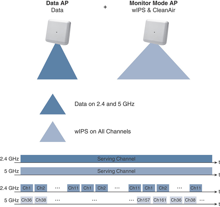
Figure 6-37 WIPS Deployment Option with Data Serving and Monitor Mode APs 3600 and 3700 series access points supporting the WSM module can use WSM radios for monitoring, while continuing to serve clients through their “standard” integrated 2.4 GHz and 5 GHz radios, as shown in Figure 6-38. One of the main advantages here is cost reduction for the physical installation, because you would not need to plan for additional access points, cables, mounting kits, and the like. The WSM module keeps scanning all channels sequentially, first on the 2.4 GHz and then on the 5 GHz band. It is slightly different from an access point in Monitor mode, which scans both bands in parallel, but technically this option supports the detection for the same attacks.
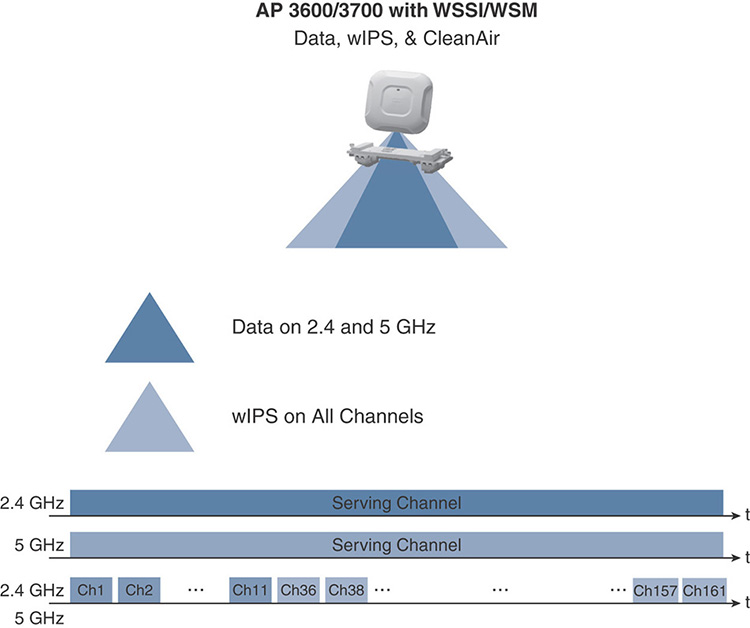
Figure 6-38 WIPS Deployment Option with 3600/3700 APs and the WSM Module To configure the WSM module for WIPS, you set the AP Sub Mode to WIPS while keeping the AP Mode set to local or FlexConnect mode, for example, for client serving purposes.
The 2800 and 3800 series access points, apart from the standard 5 GHz radio, integrate a Flexible Radio Assignment (FRA) radio, which could serve clients either on the 2.4 GHz (default behavior) or on the 5 GHz band. On top of that, the FRA radio also supports the same monitoring capabilities as a WSM module for the 3600 and 3700 series access points. If you assign the monitor role to the FRA radio, as shown in Figure 6-39, the standard 5 GHz radio can keep serving clients on that band and you can support the same WIPS options as with the previous technique. When configuring the FRA radio for the monitor role on 2800/3800 access points, clients on the 2.4 GHz band will not be supported anymore.
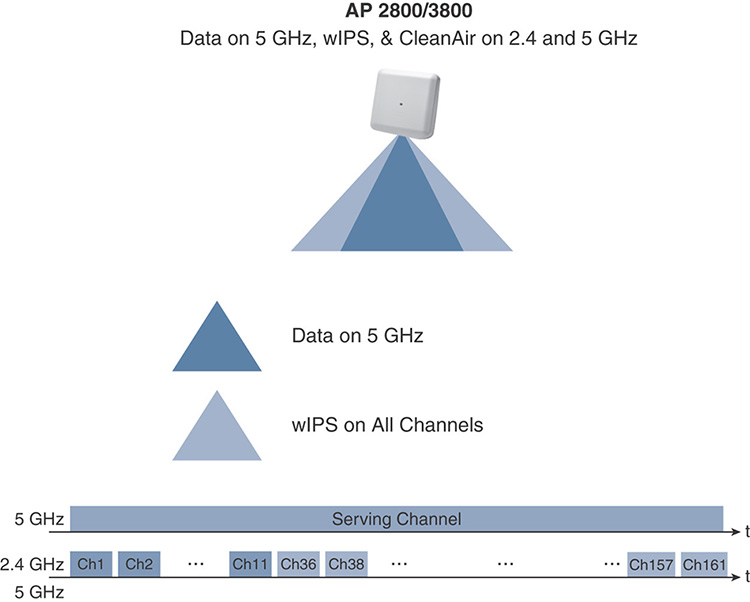
Figure 6-39 WIPS Deployment Option with 2800/3800 APs and the FRA Radio Even without WSM modules or access points supporting the FRA radio, one more option consists in keeping your access points configured for serving clients (that is, in local or FlexConnect mode) and to set their AP Sub Mode to WIPS. As shown in Figure 6-40, this configuration is called Enhanced Local Mode (ELM) and could be a good compromise for cost-sensitive deployments that still need some WIPS capabilities. With this technique, the main purpose for the access points stays serving clients and, on a best-effort basis, it can go off-channel to scan for attacks. Because of the best-effort nature of this option, ELM does not support the same full list of attacks as with the previous techniques. The full lists of supported and unsupported attacks can be found in the official “Cisco Adaptive wIPS Deployment Guide”:
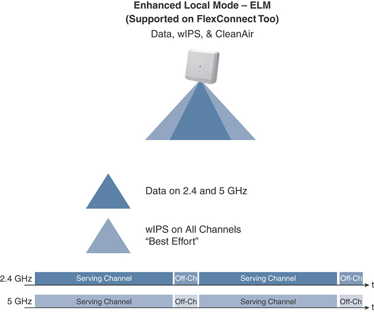
Figure 6-40 WIPS Deployment Option with Enhanced Local Mode (ELM)
After having deployed your access points with any of the aforementioned WIPS detection techniques, you can start configuring MSE 8.0 directly from Prime Infrastructure. Prime Infrastructure pushes WIPS profiles (more on this in the next paragraphs) to MSE 8.0 via SOAP/XML (on TCP port 443 on MSE), which in turn communicates with the WLC via NMSP, sharing the WIPS profile with all its access points through CAPWAP. Figure 6-41 shows a brief workflow of such interactions. When access points detect an attack, the WLC forwards the alarm to MSE, still via NMSP, for MSE to then generate an SNMP trap to Prime Infrastructure for reporting purposes.
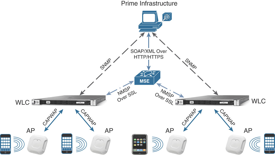
Apart from the MSE 8.0 installation itself, the entire configuration for MSE, WIPS profiles, and alarms is done through Prime Infrastructure. A key concept to note is that aWIPS usually allows reporting, analyzing, and sometimes mitigating wireless attacks. It also supports location of attackers on maps, although the accuracy depends on the deployment of access points with WIPS detection capabilities enabled. Location of attackers is available if MSE 8.0 is configured for Context Aware Services (CAS) too, with the corresponding licenses.
For the purpose of the written Wireless CCIE exam, we will focus on the main theory behind deploying WIPS profiles and their options, leaving all the details on the configuration steps to the official “Cisco Adaptive wIPS Deployment Guide”:
After you have installed MSE 8.0 and synchronized it with your WLC(s), a default WIPS profile is already applied to monitor attacks against access points and SSIDs managed by your WLC(s). You can add new profiles, either by copying the default one and modifying it, for example, or by starting from other available templates, which are predefined in Prime Infrastructure based on most common use cases (for example, education, financial, retail). WIPS profiles in Prime Infrastructure are available under Services > Mobility Services > wIPS Profiles. After having added a new profile, Prime Infrastructure asks you for an optional SSID Group to apply that profile to. If you don’t choose any SSID Group, the WIPS profile by default monitors attacks launched against access points and WLANs in your infrastructure. From the SSID Group List menu you can optionally specify whether attacks should be monitored against specific internal/external SSIDs, as shown in Figure 6-42.
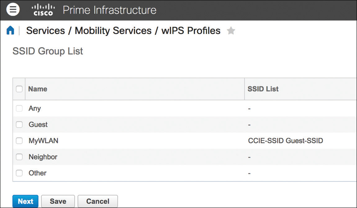
Note
Even if configuring an SSID Group is optional, several attacks and their policy rules are already preconfigured for some SSID Groups, such as MyWLAN, Guest, and Neighbor, for example. You may therefore want to specify your own organization’s SSIDs under one of those groups, according to specific attacks and policy rules that should be applied.
The next steps in a WIPS profile’s configuration are attacks and their policy rules. Even though modifying these settings is not common, policy rules under each attack let you fine tune severities for notifications and other actions. Actions under policy rules are not all the same for each attack, and they can include the generation of a forensic file, or even containment, for example. A typical example of an attack that you can optionally modify for containment is the Honeypot AP, meaning an external AP serving an open SSID with the same name as one of those specified in your organization (by default, SSIDs configured under the MyWLAN group), as shown in Figure 6-43. Policy rules for a Honeypot AP attack can be modified to include a containment action: access points from your infrastructure can attempt to send deauthentication frames to clients trying to associate to the Honeypot AP by spoofing the Honeypot AP’s radio MAC, to “contain” its impact. The other typical option for policy rules is to configure notifications in the form of a forensic file. This does not generate a typical notification like a syslog or an SNMP trap, but rather enables wireless traces on the access points for packets that trigger the alarm of an attack. Forensic files are available for download under the WIPS alarm details in Prime Infrastructure, but they create additional traffic between the WLC and MSE, so it is generally not recommended to activate them for all attacks.
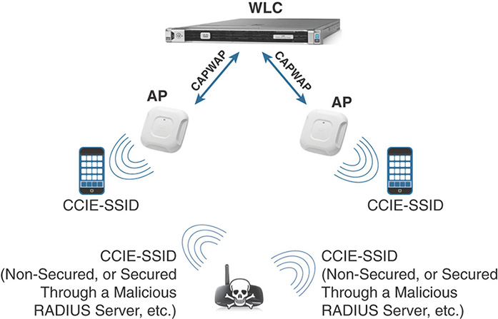
After applying a new WIPS profile to a selected controller, MSE pushes the corresponding attacks and policy rules configuration to that WLC, which applies them to its access points with WIPS monitoring capabilities enabled.
As you have seen so far, WIPS profiles enable you to apply different sets of signatures and action policies from a predefined database of attacks. This database usually covers almost any customer’s need for WIPS, but for even more attack detection capabilities the WLC supports custom IDS signatures. As the term says, these are IDS signatures for reporting purposes only and can be implemented from the WLC directly, by downloading a custom signature file to the controller under COMMANDS > Download File with the option Signature File for the file type. A signature file is a text file, where each line specifies the rules for generating an attack detection, and actions if needed. A typical custom IDS rule looks like the following:
Name = "Custom EAPOL flood", Ver = 0, Preced= 12, FrmType = data, Pattern =
0:0x0108:0x03FF, Pattern = 30:0x888E:0xFFFF, Freq=50, Quiet = 300, Action =
report, Desc="Custom EAPOL Flood Attack"
All the details on these variables and how to configure custom IDS signatures are available in the official “Wireless LAN Controller IDS Signature Parameters”:
Let’s quickly focus on the most significant parameters from the aforementioned example. As shown in Figure 6-44, apart from the self-explaining name, version, and precedence parameters, FrmType specifies the type of wireless frame for which patterns need to be checked, and this can be either for management (mgmt) or data frame types. A pattern is defined in the form of <offset>:<result>:<mask> and is considered a match if, by applying the specified mask at the offset starting from the beginning of the frame payload, you obtain the configured result. Freq tells the access point how many times patterns have to be matched in a specific interval (1 second by default, if not otherwise specified) to trigger the attack detection and action. The Quiet period in seconds is used to clear the alarm if not detected anymore within that duration. Figure 6-44 might help visualize how all the different custom IDS signature’s parameters are applied to a wireless frame displayed over Wireshark.
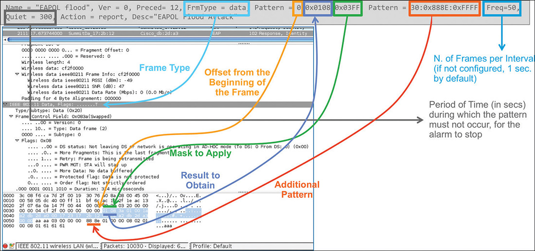
Note
When aWIPS is deployed, IDS signatures are automatically disabled on the WLC because standard IDS detectable attacks are already supported with aWIPS. If you need to support custom IDS signatures, you should reenable IDS detection on the WLC under SECURITY > Wireless Protection Policies > Custom Signatures.
NMSP
Network Mobility Service Protocol (NMSP) is the Cisco proprietary protocol for all communications between the WLC and MSE or CMX. It is TLS based on TCP port 16113 on the WLC, with CMX itself initiating the TLS tunnel, and requires a certificate’s hash validation between the WLC and MSE/CMX. For such validation, when you point CMX to a WLC by specifying the controller’s SNMP credentials, CMX uses SNMP to configure the WLC with the key hash from its own Self-Signed Certificate (SSC).
On the WLC you can see the key hash entry added by CMX under SECURITY > AAA > AP Policies > AP Authorization List, or through the command show auth-list. An entry for CMX will show up with the value LBS-SSC-SHA256 (LBS, Location Based Services) under the Certificate Type column. Usually you should not need to change this entry manually on the WLC, but if required you can find the key hash value that CMX should have pushed to the WLC by directly typing the following command from the CMX’s CLI, through the cmxadmin account: cmxctl config controllers show. The CMX’s certificate key hash used for the WLC is the one for SHA2 Key.
Another main requirement for NMSP to work is time synchronization between the WLC and CMX. The recommended best practice is to configure NTP, for both the WLC and CMX toward the same NTP server (for Prime Infrastructure too). If NTP is not available, you should configure the WLC’s clock to be the same or slightly ahead of the CMX’s one.
The easiest and quickest way to verify the NMSP connectivity between the WLC and CMX is through the commands show nmsp status on the WLC and cmxctl config controllers show on CMX.
Note
Although not specifically part of the Wireless CCIE exam, you should be aware that the NMSP communication between the WLC and CMX Cloud is based on HTTPS. This was introduced with AireOS 8.2, through a proxy HTTPS option and as a native HTTPS connection option on the WLC as of AireOS 8.3.
Summary
As you may have noticed, as a CCIE Wireless candidate, you should be aware of the different roles played by MSE 8.0 and CMX 10, the former for location use cases, aWIPS and integration with Prime Infrastructure, the latter as an evolution of those location use cases and sometime more targeted to integrating with third-party ecosystems and business applications.