Chapter 23. Configuring and Securing a WLAN AP
This chapter provides information concerning the following topics:
Initial Setup of a Wireless LAN Controller (WLC)
As an alternative to using the CLI to configure your WLC, you can use the simplified controller provisioning feature. This feature is enabled after first boot from a nonconfigured WLC, temporarily provides Dynamic Host Configuration Protocol (DHCP) service on the service port segment, and assigns PC clients a limited network address. The client can connect to the WLC using a web browser.
With a client PC connected to the WLC mapped service port, it gets an address from a limited range of 192.168.1.3 through 192.168.1.14. The WLC is assigned a fixed 192.168.1.1 address. Open a browser and connect to http://192.168.1.1 and the simplified setup wizard will help you to navigate through the minimal steps to fully configure the WLC. Figure 23-1 shows the initial page where you create the admin account, providing the admin username and password. Click Start to continue.
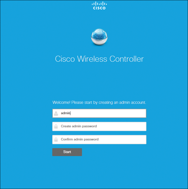
Figure 23-1 Simplified Setup Start Page
On the next page of the simplified setup wizard, shown in Figure 23-2, set up the WLC with a system name, country, date/time (automatically taken from the client PC clock), and NTP server. Also define the management IP address, subnet mask, default gateway, and VLAN ID for the management interface. Click Next to continue.

Figure 23-2 Set Up Your Controller Wizard Page
On the Create Your Wireless Networks page, shown in Figure 23-3, create the wireless network SSID, choose the security type, and specify the network/VLAN assignment. Optional is the inclusion of a Guest Network setup, a step you can use to add secure guess access with a separate network and access method for guests. Click Next to continue.
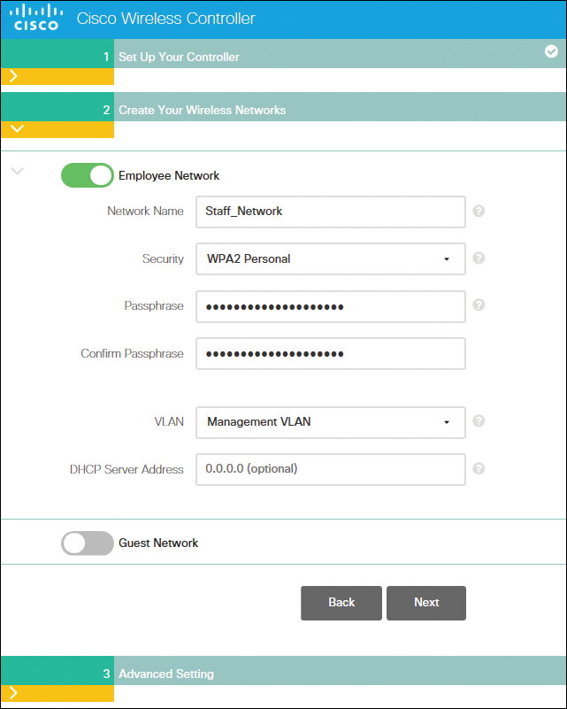
Figure 23-3 Create Your Wireless Networks Wizard Page
Note
From a security standpoint, it is advisable to configure WLANs with WPA2 with AES encryption, and 802.1X authentication. Avoid other security policies such as Open, WEP, WPA/TKIP, etc., unless absolutely needed for legacy client support. Using a pre-shared key as authentication is not recommended for enterprise environments, and should only be used for specific client compatibility scenarios. In these cases, a shared secret of 18 characters or more is advisable.
The next step of the wizard, shown in Figure 23-4, is to configure the WLC for intended RF use, and to take advantage of Cisco Wireless LAN Controller best practices defaults. Click Next to finalize the setup.
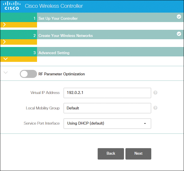
Figure 23-4 RF Parameter Optimization Settings
The simplified setup wizard will summarize the details of your configuration, as shown in Figure 23-5. Click Apply to save the configuration and reboot the WLC.
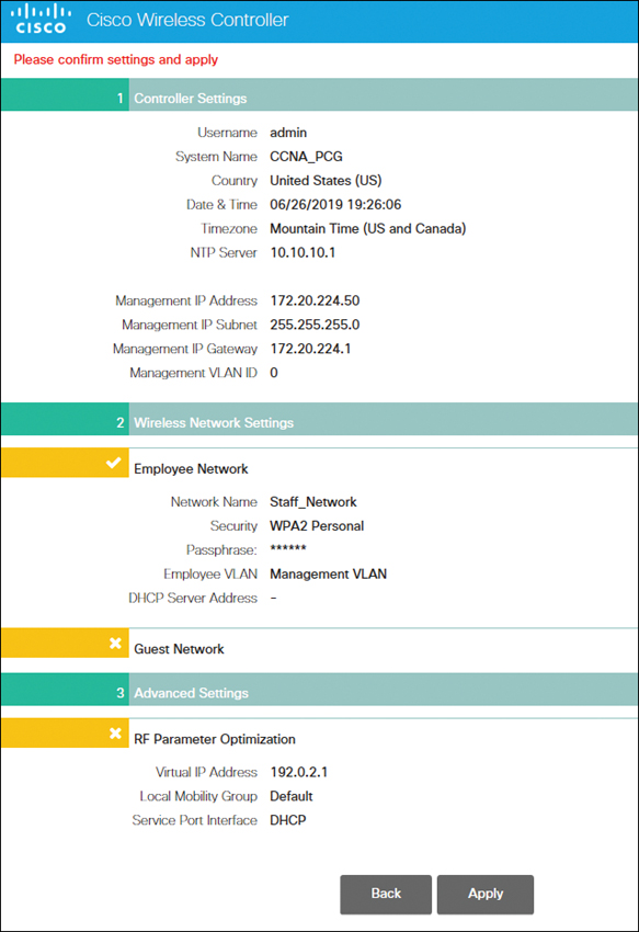
Figure 23-5 Confirming and Applying Settings
Figure 23-6 shows the reboot warning popup window. Click OK.

Figure 23-6 Rebooting the System
Once the WLC reboots, it disables the simplified set feature. You now need to use the management IP address of the WLC to log in. Figure 23-7 shows me logging in using the address of the service port.
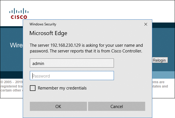
Figure 23-7 Logging in to the WLC
Monitoring the WLC
After logging in to your WLC, you see the Network Summary screen of the WLC, shown in Figure 23-8. You can’t make any configuration changes from this screen; it is for viewing what the WLC is reporting. Click Advanced in the top-right corner.
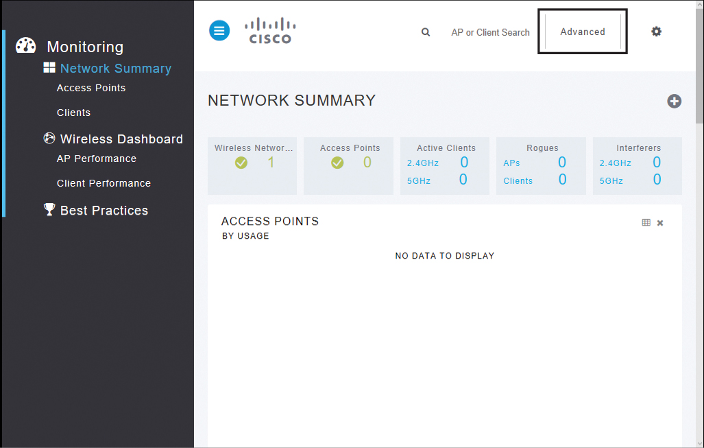
Figure 23-8 Navigating to the Advanced Monitor Summary Screen
Figure 23-9 shows the Advanced Monitor Summary screen, where you can drill down to pages to make changes to your configuration.
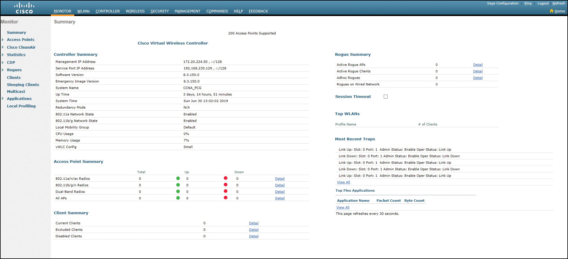
Figure 23-9 Advanced Monitor Summary Screen
Configuring a VLAN (Dynamic) Interface
Dynamic interfaces on a WLC are also known as VLAN interfaces. They are the same as VLANs for wireless clients. These interfaces allow for separate communication streams to exist on a controller’s distribution system ports. Each dynamic interface is mapped to a wireless network, which is then mapped to a VLAN network.
Starting at the Advanced Monitor Summary screen, click Controller and then click Interfaces, as shown in Figure 23-10.
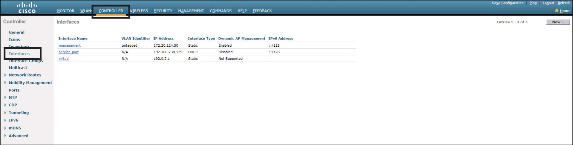
Figure 23-10 Controller Interfaces Screen
Click the New button, as shown in Figure 23-11, to create a new interface (scroll to the right side of the screen if you can’t see the New button).
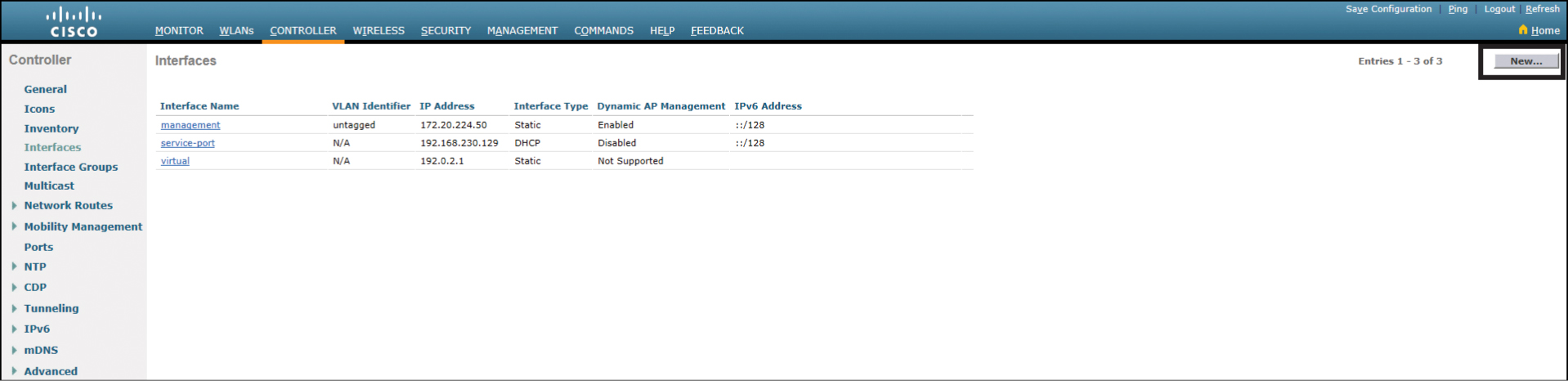
Figure 23-11 Creating a New Interface
From here you will step through the screens to enter the appropriate information for creating a new interface. Pay attention to capitalization and spacing. Figure 23-12 shows the first screen. Complete the fields and click Apply.
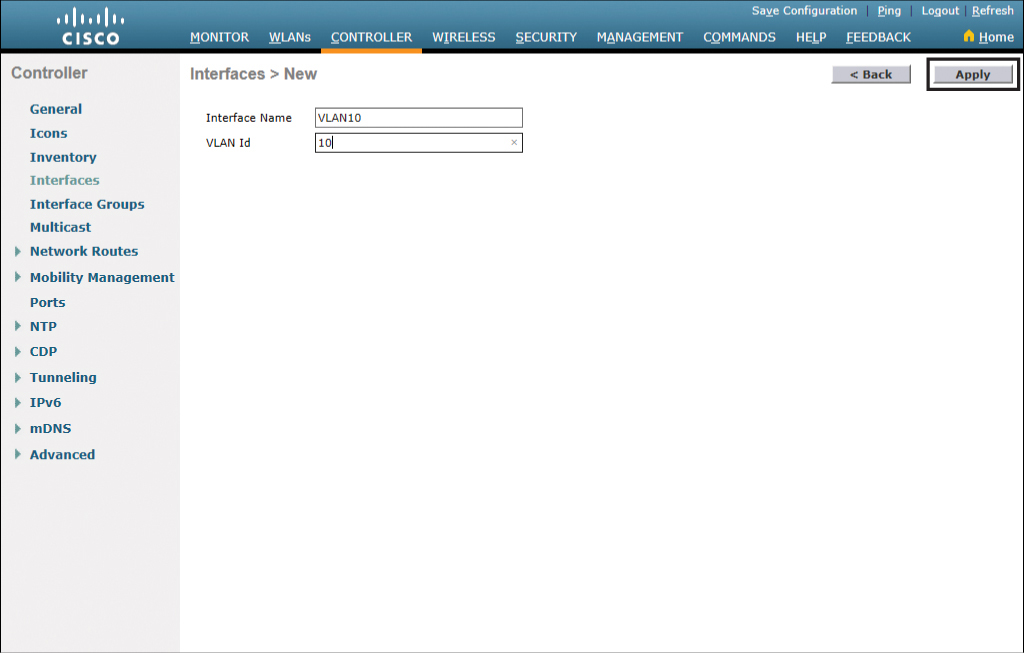
Figure 23-12 Naming a New Interface
Figure 23-13 shows the next screen for configuring this new interface. Under Physical Information, enter the port number of the interface. Remember that the physical RJ-45 connections are ports and that one or more interfaces can be configured on a port.

Figure 23-13 Entering the Port Number
Continue to the Interface Address section and enter the required IP address, netmask, and gateway information for the interface. In the DHCP Information section, enter the required DHCP server information. These sections are shown in Figure 23-14.
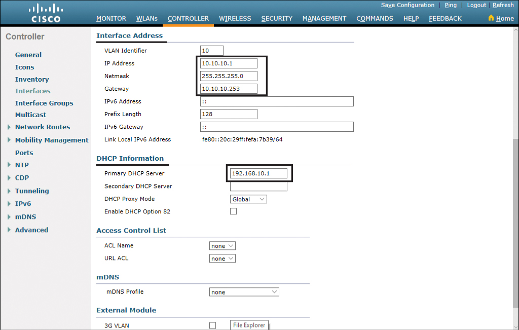
Figure 23-14 Interface Address and DHCP Information
After you have entered all the required information, scroll up and click Apply in the upper-right corner of the screen. A warning will appear reminding you that changing interface parameters may cause temporary loss of connectivity for some clients as the changes are being applied. Click OK, as shown in Figure 23-15.
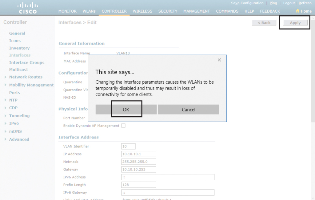
Figure 23-15 Applying Interface Changes
If you wish to test your configuration, click the Ping button in the upper-right part of the screen. Enter your new interface address and click OK, as shown in Figure 23-16.
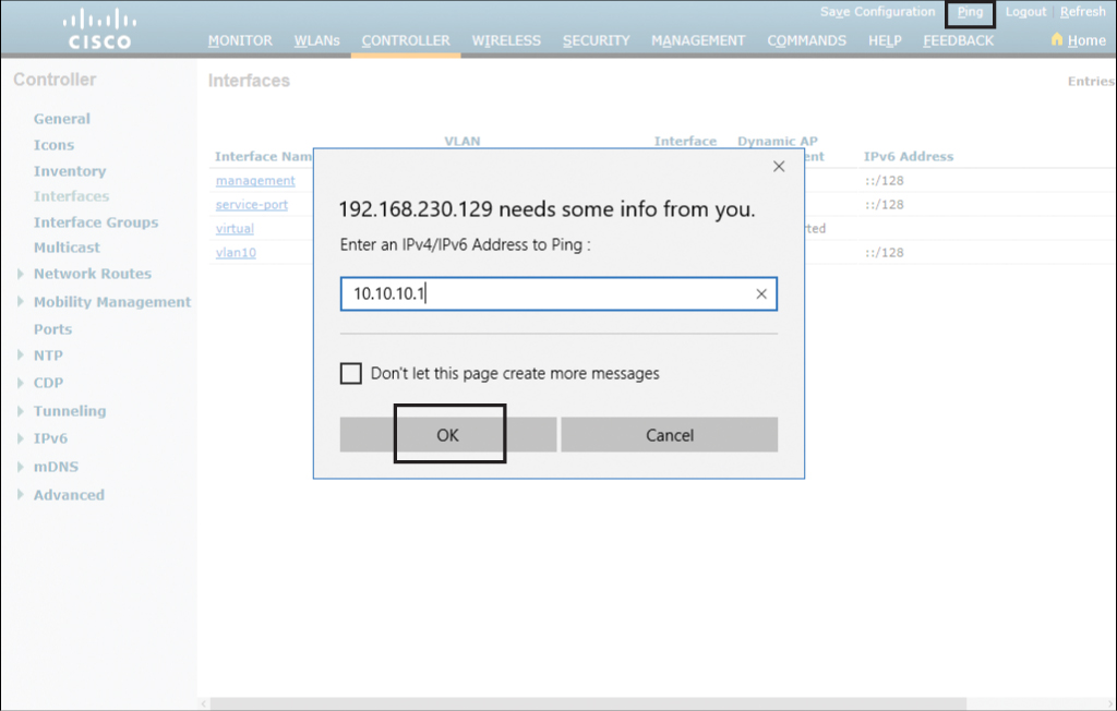
Figure 23-16 Testing the New Interface
Figure 23-17 shows a successful ping to the interface address.
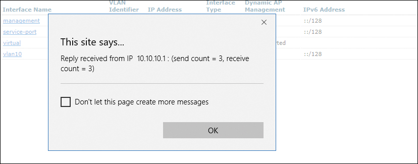
Figure 23-17 Ping Success Message
Configuring a DHCP Scope
DHCP will be used to provide IP addresses to the hosts that will be on the VLAN that you create. DHCP can be deployed from many different platforms. This example shows how to deploy DHCP from the WLC.
Starting on the Advanced Monitor Summary screen, click the Controller option in the top menu bar and then, in the navigation bar on the left side of the screen, expand the Internal DHCP Server option by clicking the blue triangle to its left, as shown in Figure 23-18.

Figure 23-18 Internal DHCP Server Option
You have two choices under Internal DHCP Server: DHCP Scope and DHCP Allocated Leases. Click DHCP Scope and the corresponding page shows that you already have a configured DHCP scope, as shown in Figure 23-19: the day0-dhcp-mgmt scope that is used with the service port during initial configuration.

Figure 23-19 DHCP Scopes
To create a new DHCP scope, scroll (if necessary) to the right of the screen and click New in the upper-right corner, as shown in Figure 23-20.

Figure 23-20 Selecting a New DHCP Scope
On the next screen, shown in Figure 23-21, enter the name of your new DHCP scope and then click the Apply button.

Figure 23-21 Naming a New DHCP Scope
You are returned to the DHCP Scopes page, shown in Figure 23-22, where you see your new scope appear in the list. It has been assigned an IP address pool of 0.0.0.0 – 0.0.0.0, it has a default lease time of one day, and its status is disabled.
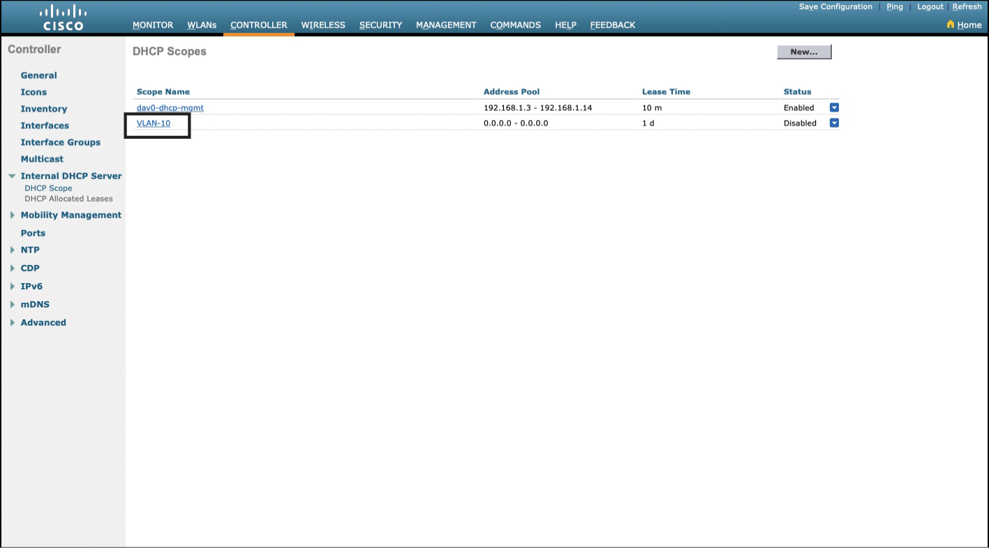
Figure 23-22 DHCP Scopes Page with New Scope Listed
To change the default 0.0.0.0 settings, click the name of the DHCP scope. You are taken to a new page, shown in Figure 23-23, where you can adjust your settings. Enter the necessary information such as pool start and end addresses, network, netmask, lease time, default routers, DNS servers, and NetBIOS name servers. Make sure to change the Status field to Enabled. Click the Apply button when finished, as indicated in Figure 23-23.
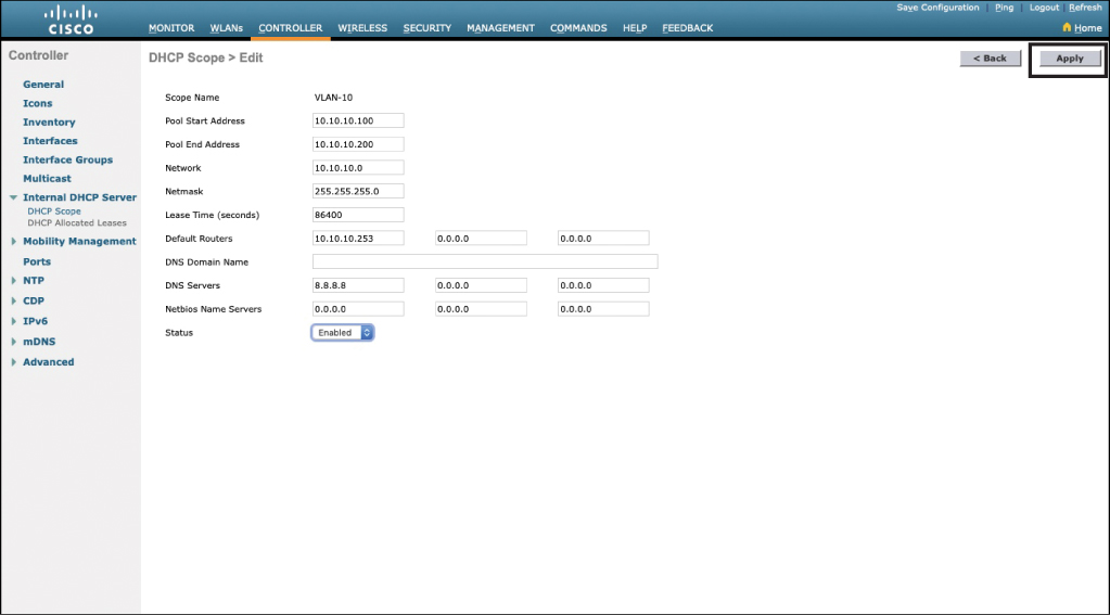
Figure 23-23 DHCP Scope Information Added
At this point you may wish to save your configuration so that it will be retained in the event of a loss of power. Click Save Configuration in the upper-right corner of the page. You will be asked to confirm this action, as shown in Figure 23-24. Click OK.

Figure 23-24 Saving Your Configuration
Configuring a WLAN
Depending on your needs, you may have a large or small number of WLANs. This section shows the steps needed to configure a WLAN on your WLC.
From the Advanced Monitor Summary screen, click WLANs in the top menu bar. You will see a list of already configured WLANs. Figure 23-25 shows one WLAN already created, the Staff_Network WLAN that was created previously with the simplified setup wizard. Click the Go button to create a new WLAN.
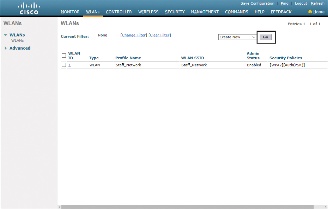
Figure 23-25 Creating a New WLAN
On the next screen, choose WLAN from the Type drop-down menu, enter the profile name and SSID, and choose your ID. The typical configuration, but not required, is to have the same profile name and SSID. Figure 23-26 shows this completed page, using 10 as the ID, to match with VLAN 10 that was created previously. Your choices for ID number range from 1 to 512. Click Apply when finished.

Figure 23-26 New WLAN Created
The next screen shows you what you entered on the last screen. Confirm it is correct. You also need to check the Enabled check box for this new WLAN, as shown in Figure 23-27.
Note
If you do not enable the WLAN, you will not be able to join the WLC from your wireless client.
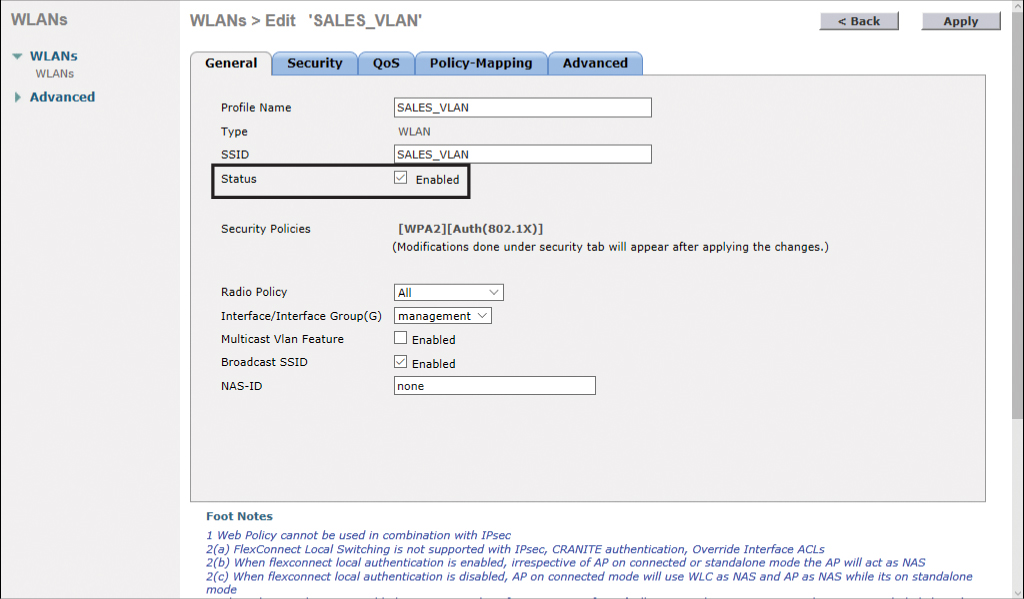
Figure 23-27 Enabling the New WLAN
Defining a RADIUS Server
To authenticate wireless clients that wish to join your WLANs, you should define at least one RADIUS server to be used by your WLC.
From the Advanced Monitor Summary screen, click the Security tab to go to the Security General page, as shown in Figure 23-28. In the navigation pane on the left side of the screen, expand AAA > RADIUS to see the options for defining a RADIUS server.

Figure 23-28 Security General Screen
Click Authentication to open the RADIUS Authentication Servers screen, shown in Figure 23-29, and click the New button to add a new RADIUS server.

Figure 23-29 Click New to Add a New RADIUS Server
Enter the required information about your RADIUS server, such as the IP address and your shared secret password, as shown in Figure 23-30. Click Apply when finished.
Note
Black dots are displayed instead of characters when you type your password in the Shared Secret and Confirm Shared Secret fields. Type carefully, because these passwords are case sensitive.
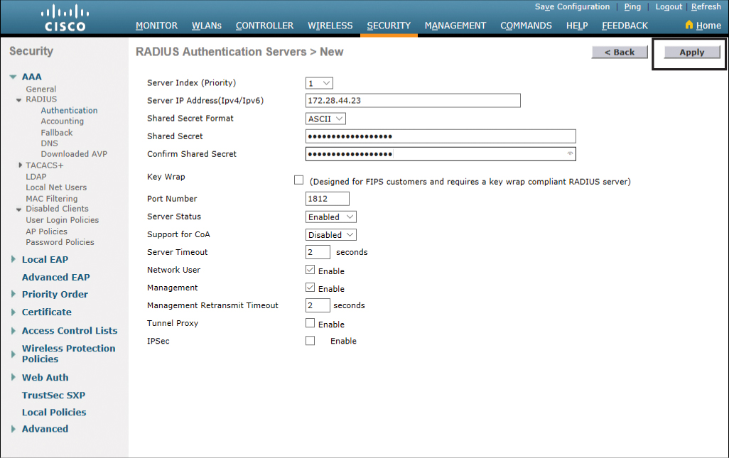
Figure 23-30 Adding Information About New RADIUS Server
The next screen shows you what you entered in the previous screen and gives you a chance to verify your information. Notice in Figure 23-31 that IPSec is set to Disabled and Admin Status is Enabled. Click Apply to continue.
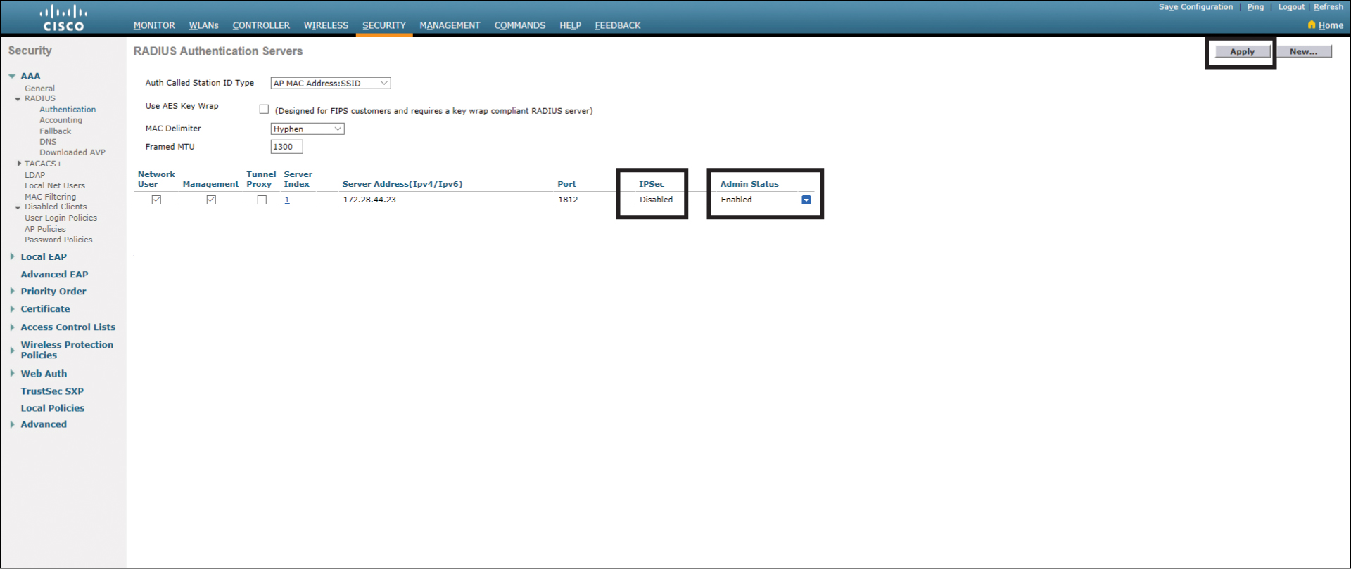
Figure 23-31 RADIUS Authentication Servers Page
Exploring Management Options
The WLC can assist you in the management of your WLANs and in the management of your WLCs.
Figure 23-32 shows the Management Summary page, with the left navigation pane displaying the options that you can configure to help manage your network.
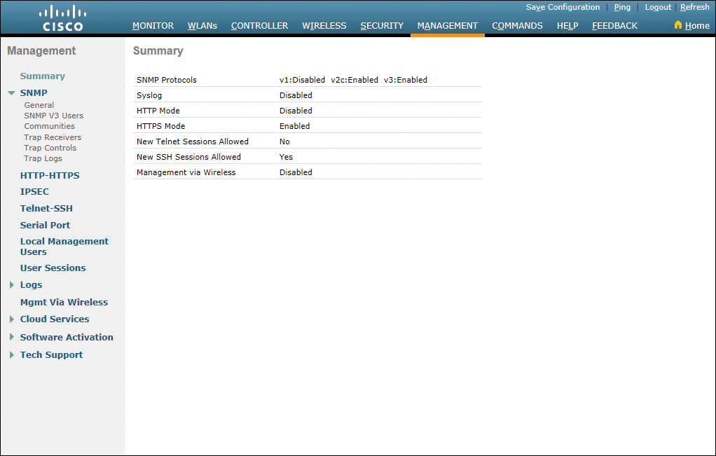
Figure 23-32 Management Summary Page
If you have multiple WLCs spread out across multiple locations, you can use the Simple Network Management Protocol (SNMP) and a centralized management console to manage your network. Figure 23-33 shows the SNMP System Summary page, which you reach by clicking General under SNMP in the navigation pane. Enter the name of your WLC, followed by its location and a contact name. Click Apply when you are finished.
Note
The name that is there to start is the name you gave to your WLC during the Simplified System Configuration wizard. If you do not wish to change the name, leave it as it is.
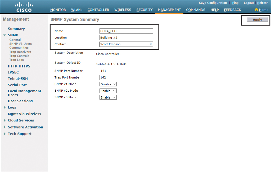
Figure 23-33 SNMP System Summary Page
To select which trap notifications you will receive, click Trap Controls under SNMP in the navigation pane; Figure 23-34 shows the SNMP Trap Controls with the General tab displayed.
Tip
Use the default settings to start, and adjust the traps to meet your needs.
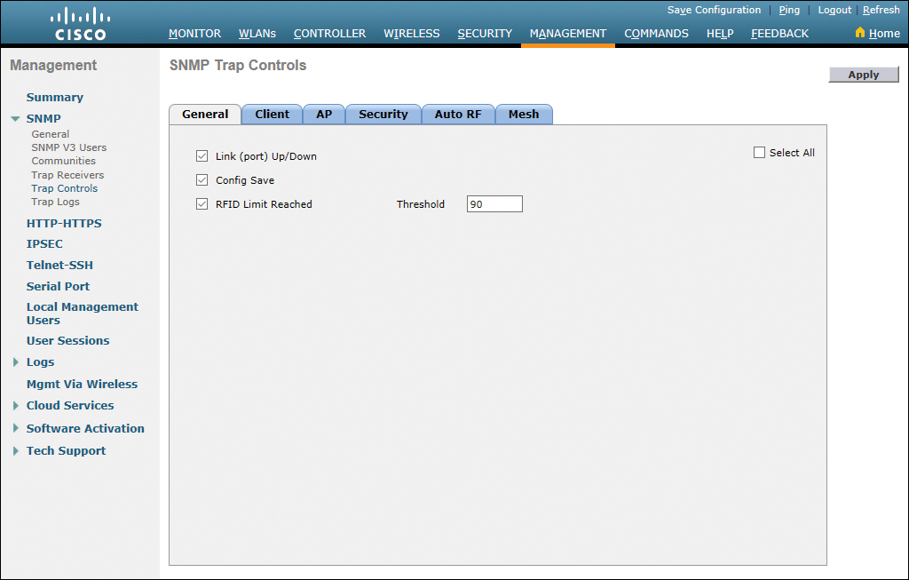
Figure 23-34 SNMP Trap Controls General Tab
Each of the other tabs—Client, AP, Security, Auto RF, and Mesh—all contain a list of the SNMP traps that can be set according to your network requirements.
Working your way down the navigation pane, Figure 23-35 shows the options available for HTTP-HTTPS configuration.
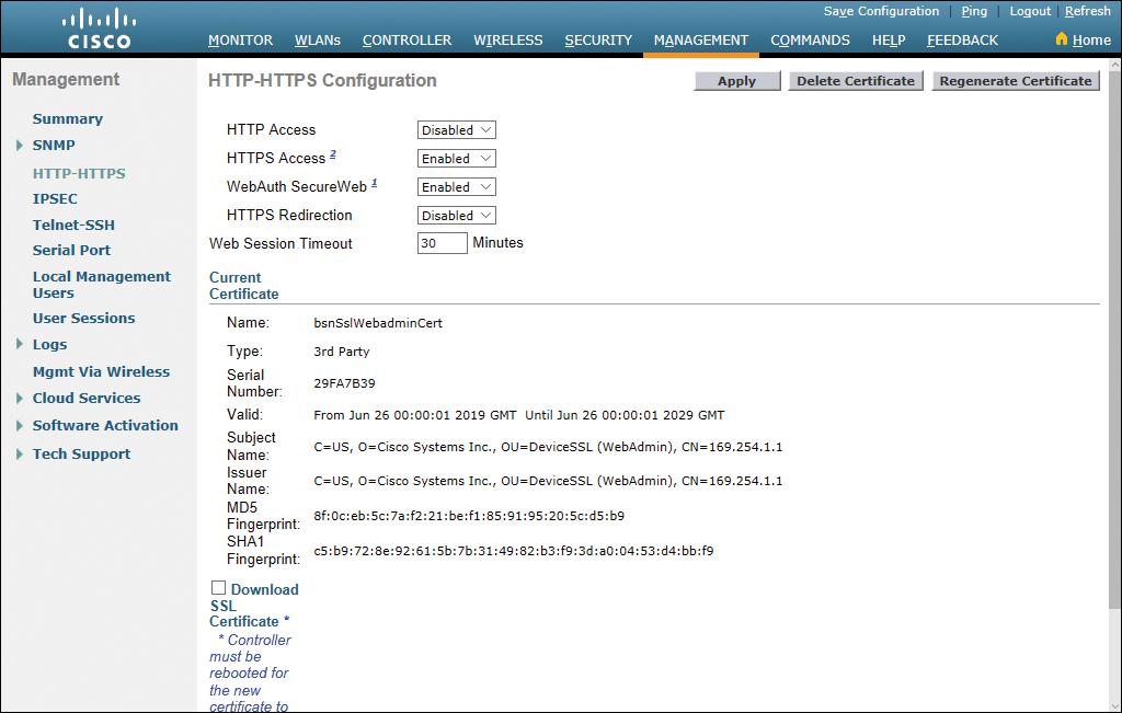
Figure 23-35 HTTP-HTTPS Configuration Page
Figure 23-36 shows the options available for Telnet-SSH configuration.
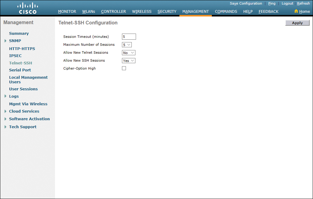
Figure 23-36 Telnet-SSH Configuration
Figure 23-37 shows the page that appears when you choose Logs > Config. Here you can set the IP address of the syslog server to which to send syslog messages. You can set up to three different syslog servers.

Figure 23-37 Syslog Configuration Page
Figure 23-38 shows the Tech Support > System Resource Information page, with settings for Current CPU Usage, Individual CPU Usage (shown only if you have multiple CPUs in your WLC), System Buffers, and Web Server Buffers.
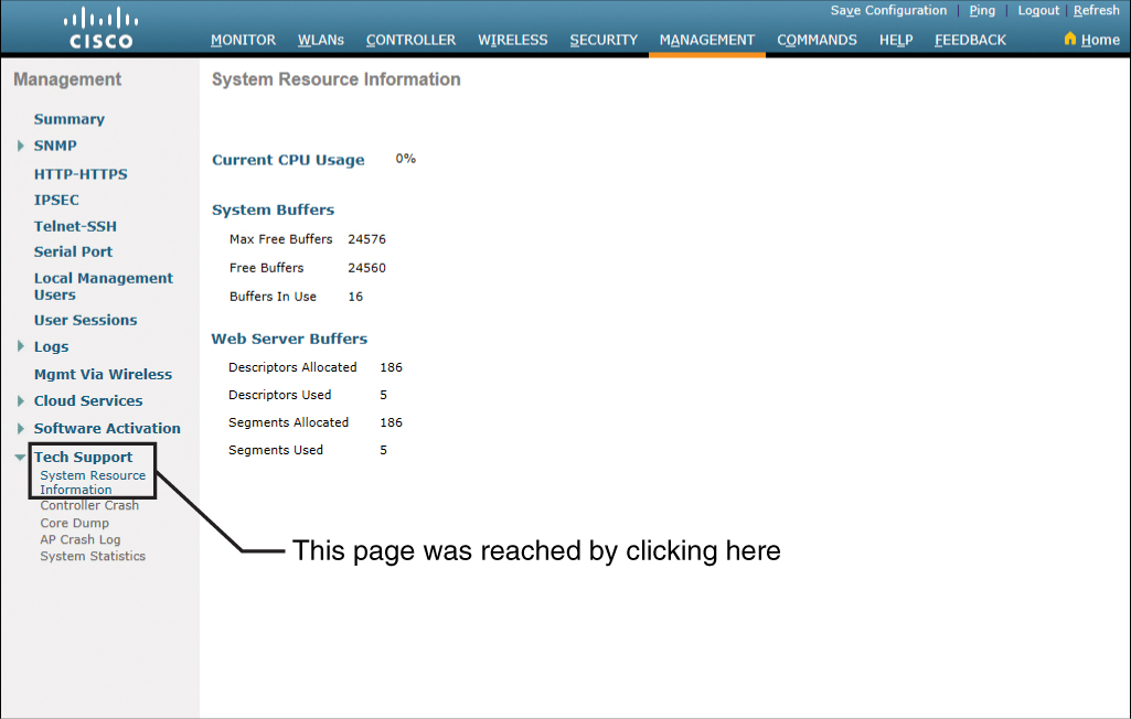
Figure 23-38 System Resource Information Page
Configuring a WLAN Using WPA2 PSK
WPA2 creates a framework for authentication and encryption. WPA2 has two modes of wireless protected access: WPA2 Personal mode, which uses WPA2-PSK; and WPA2 Enterprise mode, which uses IEEE 802.1X and EAP. This section shows you how you configure WPA2-PSK using the GUI.
Starting from the Advanced Monitor Summary screen, click WLANs in the top menu bar to see a screen that looks like Figure 23-39.

Figure 23-39 WLANs Main Screen
Create a new WLAN by clicking the Go button next to the drop-down menu showing Create New. This takes you to the screen shown in Figure 23-40, where you enter your WLAN information in the four fields: Type (leave as WLAN), Profile Name, SSID, and ID. Click Apply to commit your configuration to the WLC.

Figure 23-40 Creating and Applying a New WLAN
In the next screen, ensure that the status of your WLAN is Enabled, as shown in Figure 23-41.
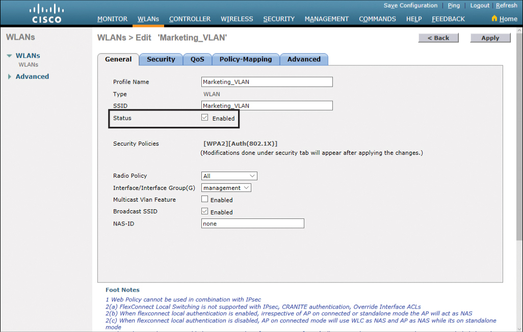
Figure 23-41 Setting the Status of the WLAN to Enabled
Next, move to the Security tab, shown in Figure 23-42. Notice the Layer 2 Security setting has defaulted to WPA+WPA2. Also notice that the default settings in the WPA+WPA2 Parameters section are to have the WPA2 Policy check box checked and the WPA2 Encryption option set to AES.

Figure 23-42 Default Setting for Layer 2 Security
Scroll down to the bottom of the page to see the options for Authentication Key Management. Click the Enable check box next to PSK. This action also unchecks the Enable check box next to 802.1X and displays new PSK Format options. Leave the default setting, ASCII, and enter your credential key in the field below it, as shown in Figure 23-43.
Note
When you type your credential key into the field, you see only black dots, and not your text. The right end of the field has a small symbol of an eye that you can click to see your text. Click it again to change back to black dots. Enter your text carefully.

Figure 23-43 Authentication Key Management
When you are satisfied with your configuration, scroll back to the top of the page and click Apply. The warning popup box shown in Figure 23-44 appears, reminding you that changing parameters will cause your WLAN to be momentarily disabled and that there may be a loss of connectivity for some clients. Click OK to continue.

Figure 23-44 Applying and Confirming Your Configuration
After applying your configuration changes, you are returned to the WLANs General tab for this specific WLAN. Notice that the Security Policies field now indicates that you are running WPA2 with PSK authentication, as shown in Figure 23-45.
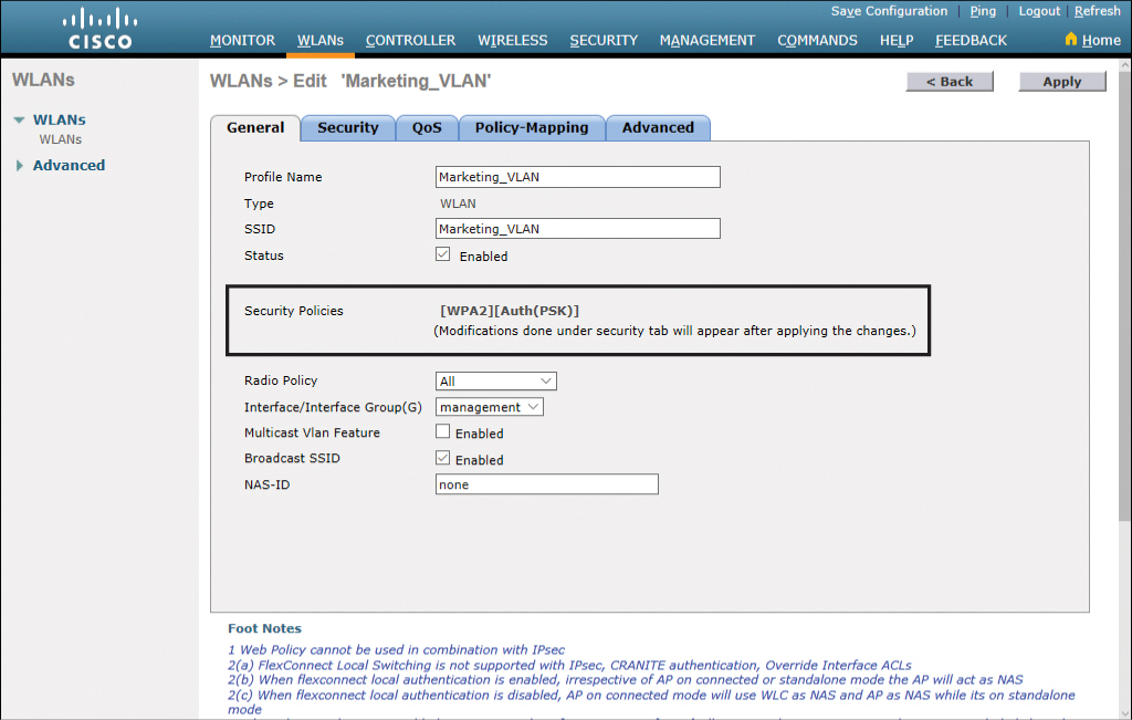
Figure 23-45 WLANs General Tab Showing Security Policies