
Chapter 6. Infrastructure Virtualization
This chapter covers the following topics:
![]() Virtual Machines and Networking
Virtual Machines and Networking
This chapter covers the following exam objectives:
![]() 4.2 Describe Infrastructure Virtualization
4.2 Describe Infrastructure Virtualization
![]() 4.2.a Difference between vSwitch and DVS
4.2.a Difference between vSwitch and DVS
![]() 4.2.b Cisco Nexus 1000V components
4.2.b Cisco Nexus 1000V components
![]() 4.2.b.1 VSM
4.2.b.1 VSM
![]() 4.2.b.2 VEM
4.2.b.2 VEM
![]() 4.2.b.3 VSM appliance
4.2.b.3 VSM appliance
![]() 4.2.c Difference between VLAN and VXLAN
4.2.c Difference between VLAN and VXLAN
The sole action of creating virtual servers is certainly not enough to provide applications to end users. In fact, these devices are expected to interact with their users, as well as other resources, making the subject of networking mandatory in any application-related conversation. Many topics related to physical networks (such as VLANs, IP addresses, and routing) are naturally part of this discussion. Additionally, the popularization of server virtualization on x86 platforms has led to the development of other solutions to support the problem of virtual machine communication. An amalgamation of both old and new concepts has spawned a new and exciting branch of networking called virtual networking.
With server virtualization performing a fundamental role in cloud computing, virtual machine (VM) traffic management has fostered intense development during the past decade. Unsurprisingly, the CLDFND exam requires knowledge about the main fundamentals of virtual networking in Cisco environments, such as both main variants of virtual switches (vSwitch and distributed virtual switch), multi-hypervisor virtual switching based on Cisco Nexus 1000V, and Virtual eXtensible LANs (VXLANs).
Fully addressing these points, this chapter investigates the motivations behind virtual networking, compares multiple solutions for virtual machine communication, and describes how Cisco has approached this new data center knowledge area.
“Do I Know This Already?” Quiz
The “Do I Know This Already?” quiz allows you to assess whether you should read this entire chapter thoroughly or jump to the “Exam Preparation Tasks” section. If you are in doubt about your answers to these questions or your own assessment of your knowledge of the topics, read the entire chapter. Table 6-1 lists the major headings in this chapter and their corresponding “Do I Know This Already?” quiz questions. You can find the answers in Appendix A, “Answers to Pre-Assessments and Quizzes.”

1. Which of the following is not applicable to virtual switching in general?
a. Responsible for virtual machine Layer 2 connectivity
b. Can be configured per host, without the use of a VM manager
c. Does not allow live migration of VMs
d. Supports LACP
e. Can belong to more than one host
2. Which of the following are differences between the VMware vNetwork Standard Switch and the VMware vNetwork Distributed Switch? (Choose four.)
a. VMware vCenter requirement
b. Uplink Port Groups
c. Allows VMotion
d. Resides in more than one host
e. Permits Port Groups with distinct load balancing methods
f. Supports LACP
3. Which of the following virtual devices can be considered distributed virtual switches? (Choose three.)
a. VMware vSS
b. Open vSwitch
c. Microsoft Virtual Network Switch
d. Linux bridge
e. VMware vDS
f. Cisco Nexus 1000V
4. Which of the following are correct about Cisco Nexus 1000V Switch for VMware vSphere? (Choose four.)
a. The communication between the VSM and VEM requires Layer 3 connectivity.
b. The communication between the VSM and VEM requires Layer 2 connectivity.
c. The VEM runs inside the VMware vSphere kernel.
d. The VEM does not run inside the VMware vSphere kernel.
e. Cisco Nexus 1000V can coexist with other virtual switches in the same host.
f. Cisco Nexus 1000V cannot coexist with other virtual switches in the same host.
g. The communication between active and standby VSMs requires Layer 3 connectivity.
h. The communication between active and standby VSMs requires Layer 2 connectivity.
5. Which of the following are correct associations of Cisco Nexus 1000V interfaces and VMware vSphere interfaces? (Choose two.)
a. Ethernet and vnic
b. vEthernet and vmk
c. vEthernet and vmnic
d. Ethernet and vmnic
e. Ethernet and vmk
6. Which of the following is not a Cisco Nexus 1000V feature?
a. vTracker
b. PortChannel
c. DHCP server
d. Private VLAN
e. TrustSec
7. Which hypervisors support Cisco Nexus 1000V? (Choose three.)
a. Microsoft Hyper-V for Windows 2008
b. Microsoft Hyper-V for Windows 2012
c. VMware vSphere
d. Xen
e. KVM
8. Which protocols are used in the VXLAN encapsulation header? (Choose two.)
a. TCP
b. GRE
c. UDP
d. IP
9. Which of the following are advantages of VXLANs over VLANs? (Choose three.)
a. Avoids MAC address table overflow in physical switches
b. Offers easier provisioning of broadcast domains for virtual machines
c. Provides more segments
d. Use IP multicast
e. Deploys flood-based learning
10. Which of the following represent improvements of Cisco Nexus 1000V Enhanced VXLAN over standard VXLAN deployments? (Choose two.)
a. Uses less MAC addresses
b. Does not require IP multicast
c. Eliminates broadcast and unknown unicast frames
d. Eliminates flooding
Foundation Topics
Virtual Machines and Networking
Chapter 5, “Server Virtualization,” explored how mainframe virtualization was adapted for x86 platforms to conceive one of the most important atomic units of a modern data center: the virtual machine. In the same chapter, you also learned why server virtualization is a key component in cloud computing, offering native agility, standardization, mobility, and resilience to applications deployed in such environments. With this background, this section zooms in on a simple (but challenging) problem: How to control VM traffic inside of a hypervisor.
An Abstraction for Virtual Machine Traffic Management
Consider the following philosophical question:
If a virtual machine cannot communicate with any other element, does it really exist?
From a technical standpoint, a virtual server obviously consumes CPU cycles, accesses memory, and saves data. Nonetheless, if the main purpose of a VM is to provide services to other systems, it certainly cannot achieve that without data connectivity.
The emulation of network adapters within virtual machines presupposes that actual traffic is exchanged across this virtual interface, including IP packets encapsulated in Ethernet frames and all ancillary signaling messages (e.g., Address Resolution Protocol [ARP]). Consequently, during the intense development of server virtualization in the early 2000s, several solutions were proposed for the following so-called challenges of VM communication:
![]() Challenge 1: Which software element should control the physical network adapter drive?
Challenge 1: Which software element should control the physical network adapter drive?
![]() Challenge 2: How should communication occur between VMs and external resources such as physical servers and routers?
Challenge 2: How should communication occur between VMs and external resources such as physical servers and routers?
![]() Challenge 3: How should VMs located in the same host be isolated from one another?
Challenge 3: How should VMs located in the same host be isolated from one another?
Depending on your level of server virtualization expertise, you likely already know the solution for all of these challenges. Nonetheless, to fully appreciate the subtleties and elegance of modern virtual networking solutions, for the moment put yourself in the shoes of a virtualization vendor in the early 2000s. As a starting point for this discussion, consider Figure 6-1.

In Figure 6-1, the same virtualized host containing two virtual machines is represented twice. And as described in the preceding list of challenges, these VMs must talk to each other and to devices located beyond the access switch, in the data center network.
Additionally, Figure 6-1 introduces two ways of representing virtual machines and their hosts. Whereas the drawing on the left depicts VMs running over the hypervisor (which I call “server vision”), the drawing on the right positions VMs at the bottom, mimicking usual network topologies where physical servers are connected below communication devices (a “network vision”).
Although the two visions might seem very similar, I highly suggest you refrain from using the server vision for networking problems. Comparing both methods, the network vision allows a more detailed exploration of networking issues in complex environments. Thus, from now on, this certification guide will employ the latter method whenever virtual networking is being discussed.
When addressing the first challenge, you will probably agree that standard VMs should not control the physical network adapter driver, not only to avoid becoming a bottleneck for VM traffic, but also to prevent other VMs from accessing this resource. As a consequence, most server virtualization vendors have decided that the hypervisor itself should control the physical network interface controller (NIC), sharing this resource with all hosted VMs.
Regarding the second challenge, try to picture how a hypervisor can use the physical NIC to forward VM data to the outside world. In this case, is it better to route (Layer 3) or bridge (Layer 2) the traffic? While routing certainly can offer better isolation to the hosted VMs, it invariably imposes operational complexities (such as subnet design and routing protocol implementation) that do not fit into most server virtualization deployments. Therefore, for the sake of simplicity, most virtual networking solutions are based on Layer 2 forwarding of Ethernet frames between VMs and the access switch.
Finally, addressing the third challenge, virtualization administrators expect to define which VMs, even running in the same hypervisor instance, should communicate with each other. As a direct result, most virtual networking solutions converged on the most traditional method of traffic isolation: the virtual local-area network (VLAN).
A VLAN is formally defined as a broadcast domain in a single Ethernet switch or shared among connected switches. Whenever a switch port receives a broadcast Ethernet frame (destination MAC address is ffff.ffff.ffff), the Layer 2 device must forward this frame to all other interfaces that are defined in the same VLAN. In other words, if two hosts are connected to the same VLAN, they can exchange frames. If not, they are isolated until an external device (such as an IP router) connects them.
Taking all of these considerations into account, and adding the goals of simplicity and flexibility, the virtual switch has emerged as the most common virtual networking solution among all hypervisors. To further delve into this software network device, the following sections explore its main characteristics, evolution, and variants.
The Virtual Switch
In the early 2000s, VMware created the concept of the virtual switch (vSwitch), which is essentially a software abstraction where the hypervisor deploys a simplified version of a Layer 2 Ethernet switch to control virtual machine traffic. At the time of this writing, this specific networking element is officially known as VMware vNetwork Standard Switch (vSS).
Note
For the sake of simplicity, I will generically refer to a virtual network device that shares the characteristics presented in this section as a vSwitch, regardless of its hypervisor.
Figure 6-2 illustrates the forwarding principles behind a generic vSwitch.

In a vSwitch, the physical NICs act as uplinks, conducting VM traffic beyond the access switch. As represented in Figure 6-2, a vSwitch can forward Ethernet frames from a virtual machine to the physical switch and vice versa. And because each VM emulates at least one NIC, real Ethernet frames traverse the virtual wire that exists between the virtual adapter and the virtual switch. After analyzing the destination MAC address in a frame, the vSwitch decides if it should send the frame to the physical NIC or to a VM whose virtual network adapter is connected to the same VLAN. In the latter situation, the data exchanged between two VMs in the same host only requires a memory-based operation.
Using VLAN tagging in its physical NICs, a vSwitch deploys more than one VLAN in these interfaces. Based on the 12-bit VLAN ID field defined in the IEEE 802.1Q standard, the virtual device can identify to which VLAN an incoming Ethernet frame belongs and also signal to the access switch the VLAN from an outgoing frame.
Like all successful abstractions, the vSwitch allows available networking knowledge (such as Layer 2 switches and VLANs) to leverage the adoption of its virtual version. Nonetheless, there are fundamental differences between a physical Ethernet switch and a vSwitch.
The first difference is the definition of a vSwitch connectivity policy, which essentially defines how the virtual device handles traffic that belongs to a group of VMs. In the case of VMware vSphere, this policy is called Port Group and it is depicted in Figure 6-3.

In the VMware vSphere architecture, the Port Group VLAN105 defines the following for a VM network connection:
![]() A VLAN ID (105)
A VLAN ID (105)
![]() Security policies (rejecting promiscuous mode and accepting MAC address change detection and forged transmits)
Security policies (rejecting promiscuous mode and accepting MAC address change detection and forged transmits)
![]() Traffic shaping (which can potentially define average bandwidth, peak bandwidth, and burst size)
Traffic shaping (which can potentially define average bandwidth, peak bandwidth, and burst size)
![]() Physical NIC teaming, specifying load balancing algorithm, network failover detection method, switch notifications, failback, and network adapter fail order
Physical NIC teaming, specifying load balancing algorithm, network failover detection method, switch notifications, failback, and network adapter fail order
The target of a connectivity policy defines the key distinction between a Port Group and a physical switch port configuration. While in the physical world we configure VLANs (and other network characteristics) on the switch interface, a Port Group is assigned to a VM network adapter. And although this difference is fairly subtle, I will explain in the next section how it radically changes the dynamics of network provisioning in cloud computing environments.
As a result, if you want two VMs to directly communicate with each other inside the same ESXi host, you just need to assign the same Port Group (or Port Groups that share the same VLAN) to their virtual adapters. As an illustration of this process, Figure 6-4 depicts the assignment of Port Group VLAN105 to the network adapter of a VM called VM-Web1.
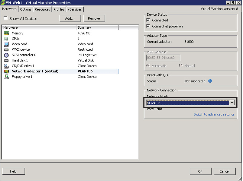
In Figure 6-4, I have used vSphere Client to change the Port Group assigned to a VM network adapter, after right-clicking the virtual machine name and selecting the desired network adapter. Through these steps, a list of available Port Groups for that host appears in the Network Label box.
In the case of the VMware vSwitch, a Port Group can only exist in a single host. Hence, as virtualization clusters were expanded into hundreds of hosts, the repetitive creation of Port Groups became a significant administrative burden.
The operational strain is especially heightened if the virtualization cluster is deploying live migration of VMs between any pair of hosts. In this case, all hosts must deploy the same vSwitch and Port Groups for a successful migration.
Note
When a VM live migrates from one host to another, the destination hypervisor sends a Reverse ARP (RARP) on behalf of the VM to update all physical switches with the VM’s new location. This gratuitous refresh only affects the physical switches that share the VLAN that contains the migrated VM. Hence, to avoid loss of connectivity between the VM and other resources, this VLAN must be enabled on all physical switches that connect both source and destination hosts.
In the next section, you will be introduced to an evolution of the vSwitch that was created to overcome these operational concerns.
Distributed Virtual Switch
As an innovation introduced in VMware vSphere version 4.0, VMware released a new virtual networking device which is formally known as the vNetwork Distributed Switch (vDS). Notwithstanding, I will generically refer to it as a distributed virtual switch (DVS) in order to define a whole class of similar solutions that was subsequently developed on other hypervisors.
Figure 6-5 depicts some of the differences between a vSwitch and a DVS in the context of VMware vSphere.


In Figure 6-5, you can observe that each vSwitch is confined to a single hypervisor instance, whereas the DVS is stretched across both hosts as if they were deploying the same virtual networking device. The reason for that perception relates to the creation of distributed Port Groups, which are produced once in VMware vCenter and automatically replicated to all hosts that are “connected” to the DVS.
Figure 6-5 also references VMware vSphere networking terminology, described in Table 6-2.

Besides its optimized provisioning, the VMware DVS has features that are not found on the VMware vSwitch, such as private VLANs, port mirroring, Link Layer Discovery Protocol (LLDP), and Link Aggregation Control Protocol (LACP).
As I have seen many times before, virtual networking novices may run into VM connectivity problems whenever more than one virtual device is deployed in a host. My original recommendation still remains: try to draw your virtual and physical topologies using the “network vision” introduced in Figure 6-1. Through this method, you will be more than adept to troubleshoot problems such as
![]() “Orphaned” virtual machines: VMs that are connected to a vSwitch (or DVS) that does not have an assigned vmnic (physical NIC).
“Orphaned” virtual machines: VMs that are connected to a vSwitch (or DVS) that does not have an assigned vmnic (physical NIC).
![]() Disjoint LANs: Happens when virtual machines are attached to virtual switches connected to distinct physical LANs
Disjoint LANs: Happens when virtual machines are attached to virtual switches connected to distinct physical LANs
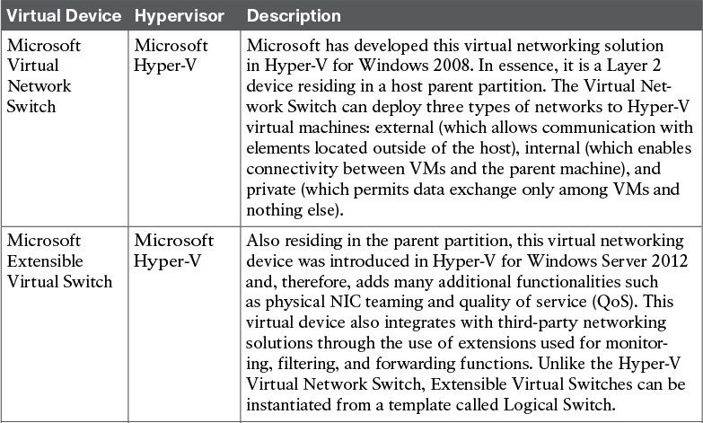
Virtual Networking on Other Hypervisors
With vendors other than VMware introducing alternative solutions to the thriving server virtualization market in the first decade of the 21st century, new virtual networking approaches were developed and adopted with varying success. Table 6-3 summarizes some of these virtual networking devices and explains how they intrinsically differ from the VMware solutions presented in the previous two sections.

Obviously, all of these solutions present advantages and drawbacks when compared with each other. However, as the next section will explore in detail, they have consistently introduced the same operational challenges to most network teams.
Networking Challenges in Server Virtualization Environments
With server virtualization rapidly advancing into most data centers, the number of virtual switch ports naturally has surpassed the number of physical switch interfaces in these environments. Furthermore, from a pure networking perspective, virtual networking has shifted the perimeter of the data center network from the access switches into the hypervisor. As a result, border-related features, such as traffic classification and filtering, may not happen in the ports that are connected to the (virtual) servers.
Although a great number of networking features were developed in virtual networking solutions, the basic operational processes on these devices remain remarkably diverse from their physical counterparts. As an illustration for this challenge, try to visualize how the following problems are addressed in your company:
![]() When a physical server is not communicating with other hosts on the network, what is the defined troubleshooting procedure?
When a physical server is not communicating with other hosts on the network, what is the defined troubleshooting procedure?
![]() Which commands does your network team execute? Which management tools are deployed?
Which commands does your network team execute? Which management tools are deployed?
Now consider what happens if a virtual machine runs into the same exact problem:
![]() Are new troubleshooting procedures required?
Are new troubleshooting procedures required?
![]() Can your network team perform them with their current operational skills and management tools?
Can your network team perform them with their current operational skills and management tools?
![]() How can the network team know about a change in the virtual network?
How can the network team know about a change in the virtual network?
As discussed in Chapter 4, “Behind the Curtain,” operational processes can certainly define whether a technology will be successfully adopted or not. And in my humble opinion, it really does not matter how innovative a solution is, if it does not fit into the operational procedures of a company IT department.
More specifically, the vast majority of virtual networking solutions discussed in the previous sections present the following difficulties to network teams and their operations:
![]() No visibility: When there is a problem happening in the “virtual wire” that links a virtual machine to a virtual networking device, traditional management tools are useless to discover a root cause. Without proper access to the VM manager, a network administrator can only “ping” this VM and verify if its MAC address is detected on the physical switches.
No visibility: When there is a problem happening in the “virtual wire” that links a virtual machine to a virtual networking device, traditional management tools are useless to discover a root cause. Without proper access to the VM manager, a network administrator can only “ping” this VM and verify if its MAC address is detected on the physical switches.
![]() VMs on wrong VLANs: Operational mistakes during the creation of virtual networking policies may provoke major problems in data center networks. For example, if a VM running a Dynamic Host Control Protocol (DHCP) server is incorrectly connected to a VLAN, it may assign incorrect IP addresses to other VMs and consequently stop all communication in that segment.
VMs on wrong VLANs: Operational mistakes during the creation of virtual networking policies may provoke major problems in data center networks. For example, if a VM running a Dynamic Host Control Protocol (DHCP) server is incorrectly connected to a VLAN, it may assign incorrect IP addresses to other VMs and consequently stop all communication in that segment.
![]() Illicit communication between VMs: A virtualization administrator may not be acutely aware of security policies that were defined and deployed in the physical network. As a consequence, VMs that should not communicate with each other may share a potentially dangerous network backdoor.
Illicit communication between VMs: A virtualization administrator may not be acutely aware of security policies that were defined and deployed in the physical network. As a consequence, VMs that should not communicate with each other may share a potentially dangerous network backdoor.
![]() Distinct control policies: Besides filtering policies described in the previous item, QoS policies defined in the physical network may not be accordingly mapped to the virtual network. Therefore, noncritical traffic may exhaust resources (such as physical NIC bandwidth) from being available for critical traffic, resulting in poor application performance.
Distinct control policies: Besides filtering policies described in the previous item, QoS policies defined in the physical network may not be accordingly mapped to the virtual network. Therefore, noncritical traffic may exhaust resources (such as physical NIC bandwidth) from being available for critical traffic, resulting in poor application performance.
![]() No virtualized DMZ: When companies must deploy demilitarized zones (DMZ) to control incoming and outgoing traffic for select servers, server hardware consolidation may directly collide with such a security directive. I personally have seen many security teams struggling with this concept, most of which ended up deploying a separate virtualization cluster for these DMZ-connected VMs.
No virtualized DMZ: When companies must deploy demilitarized zones (DMZ) to control incoming and outgoing traffic for select servers, server hardware consolidation may directly collide with such a security directive. I personally have seen many security teams struggling with this concept, most of which ended up deploying a separate virtualization cluster for these DMZ-connected VMs.
![]() Increased complexity for multi-hypervisor environments: If a data center is using more than one hypervisor, the network team will probably face additional operational difficulties to find common features in distinct virtualization platforms.
Increased complexity for multi-hypervisor environments: If a data center is using more than one hypervisor, the network team will probably face additional operational difficulties to find common features in distinct virtualization platforms.
In 2009, Cisco released an innovative (yet familiar) solution that addresses all of these operational challenges: a multi-hypervisor distributed virtual switch, further explored in the next section.
Cisco Nexus 1000V
Before virtual machines became the new atomic unit of modern data centers, Cisco recognized the importance of a concrete and secure way to manage virtual networking. Through project Swordfish, started in 2006, Cisco designed the Cisco Nexus 1000V Switch as a virtual network device running inside VMware ESXi hypervisors, leveraging a fundamental structure from each company: the Cisco NX-OS operating system from data center Nexus switches and VMware DVS.
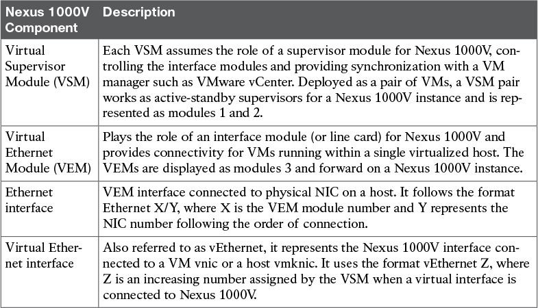
We’ll begin our exploration of Cisco Nexus 1000V with the introduction of its main components, which are displayed in Figure 6-6 and described in Table 6-4.

Virtual Services Appliances (VSAs) such as the Cisco Nexus 1110 Cloud Services Platforms can also host VSMs as a virtual service blade (VSB). Unlike how VMs are managed, VSBs are managed through procedures and NX-OS commands that are familiar to network administrators and do not require access to the VM manager. For more information about Nexus 1110, please refer to Chapter 13, “Cisco Cloud Infrastructure Portfolio.”
From an architectural standpoint, Cisco Nexus 1000V mirrors the internal structure of a chassis switch such as the Cisco Nexus 9500. Functioning equivalently to these physical devices, the switch supervisor (the VSM, in the case of Nexus 1000V) offers administrative access and centrally controls all other switch components, including the Nexus 1000V Ethernet line cards (VEMs). This comparison is further explored in Figure 6-7 and described in the following list:
![]() Each VEM forwards Ethernet frames that originate from or are destined to connected virtual machines.
Each VEM forwards Ethernet frames that originate from or are destined to connected virtual machines.
![]() The active VSM configures how the VEMs behave, defining VLANs, filters, and policies, among other functionalities. It also monitors these modules and their interfaces (Ethernet and vEthernet). Moreover, the standby VSM is constantly synchronizing with the active VSM through a shared VLAN. Should the latter fail for any reason, the standby VSM is always ready to assume the switch control operations.
The active VSM configures how the VEMs behave, defining VLANs, filters, and policies, among other functionalities. It also monitors these modules and their interfaces (Ethernet and vEthernet). Moreover, the standby VSM is constantly synchronizing with the active VSM through a shared VLAN. Should the latter fail for any reason, the standby VSM is always ready to assume the switch control operations.
![]() The majority of chassis switches utilize fabric modules to forward traffic between interface line cards. Interestingly, the physical network plays the role of a fabric module in Cisco Nexus 1000V.
The majority of chassis switches utilize fabric modules to forward traffic between interface line cards. Interestingly, the physical network plays the role of a fabric module in Cisco Nexus 1000V.

As I will further explore in Chapter 11, “Network Architectures for the Data Center: SDN and ACI,” the VSM deploys the Nexus 1000V control plane while the VEM impersonates the switch data plane. And like any other Nexus switch, Nexus 1000V uses AIPC (Asynchronous Interprocess Communication) and MTS (Message and Transaction Service) as communication protocols between both planes.
To further expose the innards of Cisco Nexus 1000V, I will detail some of its most common operational procedures. With this objective in mind, please consider the screen capture displayed in Figure 6-8, showing Nexus 1000V in VMware vCenter.

As Figure 6-8 demonstrates, Nexus 1000V is not discernible from a distributed virtual switch from a VMware vCenter administrator’s perspective. You can observe which virtual machines (and VMkernel interfaces) are connected to Nexus 1000V as well as the physical NICs (or “uplinks”) that offer external connectivity in each host.
Simultaneously, Nexus 1000V can be managed as another Cisco switch from a networking administrator’s perspective. In fact, Example 6-1 confirms this statement through a Secure Shell (SSH) session to the VSM management IP address.
Example 6-1 Cisco Nexus 1000V Command-Line Interface Session
! Administrator connects to the VSM management IP address and logs into it
vsm#
! This command verifies which modules are present in this Nexus 1000V instance
vsm# show module
! This switch has two VSMs and two VEMs
Mod Ports Module-Type Model Status
--- ----- -------------------------------- ------------------ ------------
1 0 Virtual Supervisor Module Nexus1000V active *
2 0 Virtual Supervisor Module Nexus1000V ha-standby
3 332 Virtual Ethernet Module NA ok
4 332 Virtual Ethernet Module NA ok
! Below you can find the software versions for Nexus 1000V and the VMware ESXi in the hosts
Mod Sw Hw
--- ------------------ ------------------------------------------------
1 4.2(1)SV2(2.1a) 0.0
2 4.2(1)SV2(2.1a) 0.0
3 4.2(1)SV2(2.1a) VMware ESXi 5.5.0 Releasebuild-1331820 (3.2)
4 4.2(1)SV2(2.1a) VMware ESXi 5.5.0 Releasebuild-1331820 (3.2)
! And here you can check the management IP addresses from the VSMs and the ESXi hosts
Mod Server-IP Server-UUID Server-Name
--- --------------- ------------------------------------ --------------------
1 198.18.133.40 NA NA
2 198.18.133.40 NA NA
3 198.18.133.31 422025f7-043a-87f5-c403-5b9efdf66764 vesx1.dcloud.cisco.com
4 198.18.133.32 4220955f-2062-8e3e-04b8-0000831108e7 vesx2.dcloud.cisco.com
* this terminal session
vsm#
As both Figure 6-8 and Example 6-1 hint, Nexus 1000V is “ergonomically” designed to introduce minimal changes in the operational procedures from both virtualization and networking administration teams.
From a provisioning perspective, the most crucial Nexus 1000V element is called a port profile: an NX-OS command-line interface (CLI) command that was originally developed for physical Cisco Nexus switches. Generally speaking, a port profile is a configuration template that multiple interfaces can inherit as their own setting.
While port profiles proved to be very useful for chassis switches with hundreds of ports, they are simply mandatory when you are dealing with thousands of vEthernet interfaces in a Nexus 1000V instance. To ensure consistency among all switch interfaces from a port profile, Nexus 1000V deploys a concept called atomic inheritance, which guarantees that the entire profile is applied to its members. In the case of a configuration error, the port profile and its member interfaces are rolled back to the last known acceptable state.
Example 6-2 illustrates the creation of two types of Nexus 1000V port profiles.
Example 6-2 Creating Port Profiles in Cisco Nexus 1000V
! Entering configuration mode
vsm# configure terminal
Enter configuration commands, one per line. End with CNTL/Z.
! Creating VLANs 11, 12, and 13 in this Nexus 1000V instance
vsm(config)# vlan 11-13
vsm(config-vlan)# exit
! Creating a virtual Ethernet port profile
vsm(config)# port-profile type vethernet VM-PP
! This port profile provides access to a single VLAN (11) in Nexus 1000V
vsm(config-port-prof)# switchport mode access
vsm(config-port-prof)# switchport access vlan 11
! Interfaces that inherit this port profile will immediately start working
vsm(config-port-prof)# no shutdown
! This port profile must generate a distributed Port Group in VMware vCenter
vsm(config-port-prof)# vmware port-group
vsm(config-port-prof)# state enabled
vsm(config-port-prof)# exit
! Creating an Ethernet port profile for trunk interfaces that are tagging VLANs 11, 12, and 13
vsm(config)# port-profile type ethernet UPLINK-PP
vsm(config-port-prof)# switchport mode trunk
vsm(config-port-prof)# switchport trunk allowed vlan 11-13
vsm(config-port-prof)# no shutdown
vsm(config-port-prof)# vmware port-group
vsm(config-port-prof)# state enabled
vsm(config-port-prof)# exit
vsm(config)# exit
vsm#
As explicitly commented in Example 6-2, VM-PP and UPLINK-PP are configuration templates than can be associated, respectively, to vEthernet and Ethernet interfaces. But unlike physical switches, these interfaces do not inherit port profile configurations through the Nexus 1000V CLI. Figure 6-9 depicts how VSM and vCenter are linked to each other from a provisioning perspective.

In Figure 6-9, port profiles VM-PP and UPLINK-PP automatically generated two distributed Port Groups sharing names with the port profiles. These Port Groups can be associated, respectively, to virtual machine vnics and host vmnics in any host connected to DVS “vsm” (which is the name of our Nexus 1000V).
It is very important to notice that port profiles are live templates, meaning that changes made to them are immediately reflected in their spawned Port Groups and interface heritage.
As previously stated, Nexus 1000V enables a nondisruptive operational model for both administration teams. And through this virtual switch framework, each team can effectively apply their specialized skills. In more detail:
![]() The network team creates network policies (port profiles) for vnics, vmk, and vmnics, as well as other networking configurations such as QoS policies and access control lists (ACLs) consistent with the physical network.
The network team creates network policies (port profiles) for vnics, vmk, and vmnics, as well as other networking configurations such as QoS policies and access control lists (ACLs) consistent with the physical network.
![]() The virtualization team applies these policies to virtual machines using well-known concepts (distributed Port Groups), leveraging familiar management tools (VMware vCenter) and standard procedures.
The virtualization team applies these policies to virtual machines using well-known concepts (distributed Port Groups), leveraging familiar management tools (VMware vCenter) and standard procedures.
Cisco Nexus 1000V Advanced Features
Besides the operational advantages presented in the previous section, Cisco Nexus 1000V also implements advanced networking features, such as
![]() Cisco Discovery Protocol (CDP): For quick topology discovery integrated with the large majority of Cisco networking devices.
Cisco Discovery Protocol (CDP): For quick topology discovery integrated with the large majority of Cisco networking devices.
![]() Private VLANs: Isolate a virtual machine (or group of VMs) from other VMs connected to the same VLAN.
Private VLANs: Isolate a virtual machine (or group of VMs) from other VMs connected to the same VLAN.
![]() Switched Port Analyzer (SPAN) and Encapsulated Remote SPAN (ERSPAN): Provide traffic mirroring from virtual Ethernet interfaces to an analysis tool connected to another vEthernet port and located within a Layer 3 network, respectively.
Switched Port Analyzer (SPAN) and Encapsulated Remote SPAN (ERSPAN): Provide traffic mirroring from virtual Ethernet interfaces to an analysis tool connected to another vEthernet port and located within a Layer 3 network, respectively.
![]() Quality of Service (QoS): Provides traffic prioritization in the physical NICs.
Quality of Service (QoS): Provides traffic prioritization in the physical NICs.
![]() DHCP Snooping, IP Source Guard, and Dynamic ARP Inspection: Advanced security functionalities that enable Nexus 1000V to monitor and enforce correctly assigned IP addresses, avoiding exploits such as rogue DHCP servers, invalid ARP messages, and false IP addresses.
DHCP Snooping, IP Source Guard, and Dynamic ARP Inspection: Advanced security functionalities that enable Nexus 1000V to monitor and enforce correctly assigned IP addresses, avoiding exploits such as rogue DHCP servers, invalid ARP messages, and false IP addresses.
![]() TrustSec: Enables Nexus 1000V to participate on this Cisco security architecture, which in effect allows device authentication as well as the aggregation of diverse hosts into security groups, vastly simplifying firewall rules and ACLs across multiple network domains (campus and data center, for example).
TrustSec: Enables Nexus 1000V to participate on this Cisco security architecture, which in effect allows device authentication as well as the aggregation of diverse hosts into security groups, vastly simplifying firewall rules and ACLs across multiple network domains (campus and data center, for example).
Besides network features derived from physical devices, Nexus 1000V has also fostered innovation in “pure” virtual networking in many different ways. One example is the vTracker feature, which improves visibility over virtual machine’s status and behavior through the Nexus 1000V CLI.
Example 6-3 depicts two simple vTracker applications.
Example 6-3 Cisco Nexus 1000V vTracker Examples
! Enabling the vTracker feature
vsm(config)# feature vtracker
! Now I want to observe the status from a virtual machine called WebServer-A
vsm(config)# show vtracker vm-view info vm WebServer-A
! vTracker shows many characteristics from the VM, including location (VEM 4), guest OS
(Ubuntu), power state, resource usage, and uptime
Module 4:
VM Name: WebServer-A
Guest Os: Ubuntu Linux (64-bit)
Power State: Powered On
VM Uuid: 423641c8-22a2-0c2f-6d5e-9e0cf56c02e0
Virtual CPU Allocated: 1
CPU Usage: 0 %
Memory Allocated: 256 MB
Memory Usage: 2 %
VM FT State: Unknown
Tools Running status: Running
Tools Version status: unmanaged
Data Store: Demo_Datastore
VM Uptime: 3 hours 44 minutes 25 seconds
! This command offers visibility over the last five VM live migrations with VMs
connected to this Nexus 1000V instance
vsm(config)# show vtracker vmotion-view last 5
Note: VM Migration events are shown only for VMs currently managed by Nexus 1000v.
* '-' = Module is offline or no longer attached to Nexus1000v DVS
--------------------------------------------------------------------------------
VM-Name Src Dst Start-Time Completion-Time Mod Mod
--------------------------------------------------------------------------------
Windows7-A 3 4 Tue Apr 28 16:35:33 2015 Tue Apr 28 16:35:49 2015
WebServer-A 4 3 Tue Apr 28 16:35:14 2015 Tue Apr 28 16:35:32 2015
--------------------------------------------------------------------------------
! Virtual machine Windows7-A has migrated from VEM3 to VEM4 in 16 seconds. Virtual
machine WebServerA has migrated from VEM4 to VEM3 within 18 seconds.
In Example 6-3, vTracker is enabled through the feature command, which is a common procedure for additional function activation on a modular network operating system such as NX-OS. Later in the example, two vTracker views are explored:
![]() VM view: Where several virtual machine attributes (such as guest OS) and resource utilization levels (such as CPU and memory) are exposed to network administrators aiming to support VM troubleshooting
VM view: Where several virtual machine attributes (such as guest OS) and resource utilization levels (such as CPU and memory) are exposed to network administrators aiming to support VM troubleshooting
![]() vMotion view: Where live migrations of VMs connected to Nexus 1000V are detailed for network administrators
vMotion view: Where live migrations of VMs connected to Nexus 1000V are detailed for network administrators
Another innovation from the Cisco Nexus 1000V architecture was created to provide more automation for common procedures and to increase network-related visibility for the server virtualization team. In summary, the Cisco Virtual Switch Update Manager (VSUM) offers the following features through the VMware vSphere Web Client:
![]() Cisco Nexus 1000V fully automated installation
Cisco Nexus 1000V fully automated installation
![]() Automatic creation of basic Cisco Nexus 1000V port profiles
Automatic creation of basic Cisco Nexus 1000V port profiles
![]() Cisco Nexus 1000V automated NX-OS version upgrade
Cisco Nexus 1000V automated NX-OS version upgrade
Note
Like many other solutions that will be discussed in Chapter 7, “Virtual Networking Services and Application Containers,” VSUM is installed as a virtual appliance, which is basically a “ready-to-run” virtual machine customized to perform a dedicated function. The most popular virtual appliance file format is called Open Virtual Appliance (OVA).
Finally, highlighting its great fit for cloud computing, Nexus 1000V also supports an extensible REST application programming interface (API) for software-based configuration.
Cisco Nexus 1000V: A Multi-Hypervisor Platform
Cisco has successfully extended its capabilities to other hypervisors, providing consistent and advanced features to virtualization environments based on Microsoft Hyper-V and Linux KVM.
Figure 6-10 delineates the architecture of Nexus 1000V for Microsoft Hyper-V and Nexus 1000V for Linux KVM.

As with the VMware vSphere version, in both cases the VSM continues to be intrinsically linked to a VM manager, which are Microsoft System Center Virtual Machine Manager (for Hyper-V) and OpenStack Nova (for Linux KVM). And similarly, the creation of port profiles on Nexus 1000V automatically produces matching connectivity policies in both hypervisors (more specifically, port classifications in Hyper-V and network profiles in KVM).
In addition to its astounding number of features, another advantage of adopting Nexus 1000V in multi-hypervisor environments is that it offers operational simplicity in such scenarios.
As an illustration, envision an OpenStack-based cloud computing scenario employing three hypervisors: VMware vSphere, Microsoft Hyper-V, and Linux KVM. A cloud architect should pick the most appropriate physical NIC high availability methods according to each adopted virtual networking device from the extensive list of currently available options for each virtual switch:
![]() VMware vSphere vNetwork Standard Switch: Route based on originating virtual port ID, route based on source MAC hash, use explicit failover order, or route based on IP hash
VMware vSphere vNetwork Standard Switch: Route based on originating virtual port ID, route based on source MAC hash, use explicit failover order, or route based on IP hash
![]() VMware vSphere vNetwork Distributed Switch: Route based on originating virtual port ID, route based on source MAC hash, route based on physical NIC load, use explicit failover order, or route based on IP hash
VMware vSphere vNetwork Distributed Switch: Route based on originating virtual port ID, route based on source MAC hash, route based on physical NIC load, use explicit failover order, or route based on IP hash
![]() Microsoft Hyper-V Virtual Extensible Switch: Active-standby, all address hash, or port mode
Microsoft Hyper-V Virtual Extensible Switch: Active-standby, all address hash, or port mode
![]() KVM with Linux bridge: Spanning Tree Protocol (IEEE 802.1Q), active-backup bonding, round-robin, XOR bonding, or LACP
KVM with Linux bridge: Spanning Tree Protocol (IEEE 802.1Q), active-backup bonding, round-robin, XOR bonding, or LACP
![]() KVM with Open vSwitch: Active-backup bonding, source MAC load balancing, TCP load balancing, LACP
KVM with Open vSwitch: Active-backup bonding, source MAC load balancing, TCP load balancing, LACP
As you can easily conclude, the multitude of choices may become overwhelming for architects who intend to deploy a standard method of upstream communication for virtual machines.
Note
Most virtual switches, including Nexus 1000V, employ loop-avoidance techniques to cease the use of Spanning Tree Protocol within the hypervisor (for example, most virtual devices cannot forward frames between physical NICs). In Chapter 10, “Network Architectures for the Data Center: Unified Fabric,” I will discuss why STP has become an unsuitable solution for modern data center networks.
Properly addressing this challenge, Cisco Nexus 1000V builds a homogenous virtual network layer distributed over different hypervisors, offering uplink high availability in the exact same way for the whole cloud. Example 6-4 illustrates how Nexus 1000V implements PortChannels, which are host uplinks composed of multiple physical NICs, on multiple hypervisors.
Example 6-4 Building Automatic PortChannels in Cisco Nexus 1000V
! The question mark shows the available options for load balancing traffic on
PortChannels
vsm(config)# port-channel load-balance ethernet ?
! Each VEM will load balance traffic in a PortChannel by hashing the following
addresses, ports, and identifiers to a numerical value that selects one of the
operational links.
dest-ip-port Destination IP address and L4 port
dest-ip-port-vlan Destination IP address, L4 port and VLAN
destination-ip-vlan Destination IP address and VLAN
destination-mac Destination MAC address
destination-port Destination L4 port
source-dest-ip-port Source & Destination IP address and L4 port
source-dest-ip-port-vlan Source & Destination IP address, L4 port and VLAN
source-dest-ip-vlan Source & Destination IP address and VLAN
source-dest-mac Source & Destination MAC address
source-dest-port Source & Destination L4 port
source-ip-port Source IP address and L4 port
source-ip-port-vlan Source IP address, L4 port and VLAN
source-ip-vlan Source IP address and VLAN
! "source-mac" is the default algorithm
source-mac Source MAC address
source-port Source L4 port
source-virtual-port-id Source Virtual Port Id
vlan-only VLAN only
! Changing a port profile created in Example 6-2
vsm(config)# port-profile UPLINK-PP
! Checking the available aggregation modes for the automatic PortChannels
vsm(config-port-prof)# channel-group auto mode ?
active Set channeling mode to ACTIVE
on Set channeling mode to ON
passive Set channeling mode to PASSIVE
! With ACTIVE mode, Nexus 1000V will start aggregation negotiation with the upstream
physical switch. On the other hand, PASSIVE mode will wait for the upstream switch to
start the negotiation. ON mode will already aggregate the uplinks without any
negotiation.
! In this case, I will choose ACTIVE mode
vsm(config-port-prof)# channel-group auto mode active
As you can verify in Example 6-4, Cisco Nexus 1000V provides myriad load balancing methods for the upstream VM traffic (sent by the virtual machines to the physical network). Ideally, the chosen method should match the load balancing algorithm for the downstream traffic (from the access switches).
Example 6-4 also depicts the choice of aggregation negotiation mode on Nexus 1000V, which must be compatible with the configured mode on the physical switches. With Nexus 1000V deploying ACTIVE mode, the upstream switches may deploy ACTIVE or PASSIVE mode.
After the port profile is changed as shown in Example 6-4, as the connectivity policy UPLINK-PP is assigned to more physical NICs in a host, its VEM will automatically aggregate up to eight of these uplinks in a single PortChannel.
Note
In Chapter 10, I will explore a feature called Virtual PortChannel (vPC), which allows the aggregation of multiple uplinks connected to a pair of physical Nexus switches.
Virtual eXtensible LAN
In 2010, Cisco, VMware, and other IT vendors submitted an Internet Engineering Task Force (IETF) draft proposal defining a cutting-edge technology called Virtual eXtensible LAN (VXLAN). Primarily, VXLAN technology was created to address significant limitations VLANs bring to dynamic server virtualization environments and cloud computing projects.
Figure 6-11 serves as an overview to the discussion of why VLANs are considered “villains” (pun intended) in some data centers.
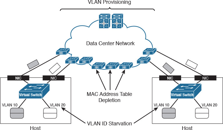
VLAN provisioning in the physical network constitutes the first challenge for VMs using VLANs. In Figure 6-11, there are two hosts that may or may not belong to the same virtualization cluster. Imagine that each host is deploying VMs connected to two VLANs: 10 and 20. As you may easily infer, these VMs can communicate with their counterparts in the other host only if the network administration team has already configured both VLANs in every switch and possible connections between both hosts.
Obviously, this configuration procedure can become unbearably cumbersome and slow as the number of network devices increases. In addition, the potential live migration of VMs to any host in the data center severely aggravates the situation. The reason is that network administrators must enable these new VLANs in all switches and trunks of the data center network to avoid isolated VMs.
Caution
Although I have seen it done in some data centers, I definitely do not recommend the pre-provisioning of all 4094 possible VLANs in every network trunk. Although it may apparently save time and effort, this “worst practice” may result in unwanted traffic in many ports of the network as well as STP scalability issues.
VLAN ID starvation is a second challenge that can become a growing preoccupation in cloud computing environments. Because a physical network can deploy only 4094 VLANs (1 to 4094 according to the IEEE 802.1Q standard) to isolate hosts, a cloud will eventually face an absolute limit if it is reserving one or more VLANs per tenant.
While not as noticeable as the previous challenges, MAC address table depletion is already a preoccupation for many network teams all over the world. In a standard Ethernet network, every switch ends up learning the MAC address of all VMs. Therefore, a relatively small data center composed of eight racks containing 40 virtualized servers with 100 VMs each may overload all access switches that support less than 32,000 MAC address entries.
As a possible reaction, an overwhelmed switch may stop MAC address learning and start to forward more unknown traffic received on one interface to all the other ports, in a phenomenon called flooding. With more switches sharing this fate, a data center network may simply become unusable.
VXLAN in Action
Basically, a VXLAN segment is a broadcast domain built through the encapsulation of Ethernet frames into IP packets. Figure 6-12 details how this encapsulation happens.

As Figure 6-12 shows, each VXLAN packet encapsulates a single Ethernet frame in an IP packet containing a User Datagram Protocol (UDP) datagram with an extra header for specific VXLAN fields. The most important field is called VNI (VXLAN Network Identifier), which defines the VXLAN packet segment. Through this 24-bit identifier, virtual machines can be isolated in potentially 16,777,215 VXLAN segments. Anyhow, VXLAN segments are assigned to the range 4096 to 16,777,215 to further heighten the perception that a VXLAN segment replaces a VLAN segment.
Note
In Figure 6-12, T/L means Type/Length, which may represent either the type of data on the payload or the frame length, depending on its value. FCS means frame check sequence, which is a 32-bit cyclic redundancy check (CRC) used to detect transmission errors in Ethernet links.
To support a more comprehensive analysis of this technology, Figure 6-13 illustrates a working VXLAN scenario.

In Figure 6-13, a pair of virtualized servers is hosting two virtual machines each, using two distinct VXLAN segments: 5000 and 6000. By definition, any device that can generate and process VXLAN encapsulated traffic is called a VXLAN tunnel endpoint (VTEP). In Figure 6-13, both virtual switches are the only depicted VTEPs.
Ultimately, a virtual machine should not discern if it is connected to a VXLAN- or VLAN-based broadcast domain. However, according to the VXLAN IETF standard (RFC 7348), as soon as a VM is connected to a VXLAN segment, its VTEP must register itself into the network as a member of the multicast group assigned to the VXLAN. This registration procedure may be accomplished through an Internet Group Multicast Protocol (IGMP) Join message. In this case, the connections of the VMs to the vSwitch generate IGMP Join messages to groups 239.5.5.5 (VXLAN 5000) and 239.6.6.6 (VXLAN 6000).
Using this information, the data center network is aware that VTEP1 and VTEP2 are part of both multicast groups.
Note
For a correct communication between VMs connected to the same VXLAN segment, the VXLAN ID and multicast group pair should be consistent on all VTEPs. If desired, two or more VXLAN segments can share the same group.
Similar to a standard Ethernet switch, a VTEP maintains a MAC address table. However, instead of associating a MAC address to an interface, a VTEP additionally associates a VM MAC address to a remote VTEP IP address. The MAC address learning process is described next via an example.
To begin the example, assume that the MAC address tables from both vSwitches are empty and that VM1 sends an ICMP Echo message (ping) to VM2. Because VM1 does not know VM2’s MAC address, it sends an ARP request that essentially states the following: “Hello, people in my network segment. Whoever has the following IP address, please inform me of your MAC address.”
By definition, an ARP request is a broadcast message and therefore must be forwarded to all machines connected to the broadcast domain (VXLAN 5000). Upon receiving the ARP request, vSwitch1 does the following:
![]() If the VM manager has not inserted its MAC address into vSwitch1’s MAC address table (which is the case for most virtual switches), vSwitch1 learns VM1’s MAC address in Interface1.
If the VM manager has not inserted its MAC address into vSwitch1’s MAC address table (which is the case for most virtual switches), vSwitch1 learns VM1’s MAC address in Interface1.
![]() Encapsulates the Ethernet frame into a VXLAN packet using VTEP1 as its source IP address and the VXLAN multicast group (239.5.5.5) as the destination IP address.
Encapsulates the Ethernet frame into a VXLAN packet using VTEP1 as its source IP address and the VXLAN multicast group (239.5.5.5) as the destination IP address.
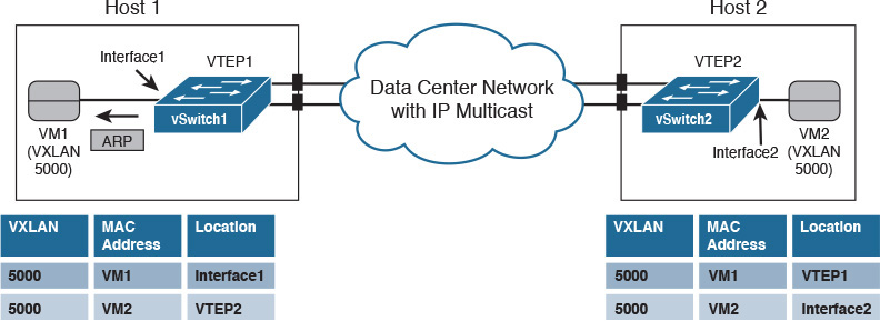
Figure 6-14 depicts the exact moment after the VXLAN-encapsulated ARP request leaves Host1 toward the data center network. Using IP multicast forwarding, the data center network replicates the packet and sends a copy to each member of the 239.5.5.5 group (except, of course, VTEP1). As a result, the VXLAN packet reaches vSwitch2, immediately updating its MAC address table as shown in Figure 6-15.


Note
At this very moment, any other VTEP deploying VXLAN 5000 also receives the ARP request and updates its MAC address table with the same entry (VM1-VTEP1 pair) in VXLAN 5000.
Thus, vSwitch2 decapsulates the VXLAN packet and forwards the ARP request to its lonely local member of the segment: VM2. Processing the frame, VM2 sends a unicast ARP reply directed to VM1’s MAC address informing VM1 of its MAC address. After receiving this message, vSwitch2 does the following:
![]() Updates its MAC address table with VM2’s MAC address in Interface2
Updates its MAC address table with VM2’s MAC address in Interface2
![]() Encapsulates the ARP reply into a VXLAN packet using VTEP2 as its source IP address and VTEP1 as the destination IP address
Encapsulates the ARP reply into a VXLAN packet using VTEP2 as its source IP address and VTEP1 as the destination IP address
Figure 6-16 displays the instant after the encapsulated frame leaves Host2.

The VXLAN packet containing the ARP reply is naturally routed to VTEP1 (vSwitch1). And as Figure 6-17 illustrates, this virtual device
![]() Updates its MAC address table with the information that VM2 can be reached through VTEP2
Updates its MAC address table with the information that VM2 can be reached through VTEP2
![]() Decapsulates the VXLAN 5000 packet and sends the ARP reply to VM1
Decapsulates the VXLAN 5000 packet and sends the ARP reply to VM1
From this moment on, both VMs can forward unicast Ethernet frames to each other with their associated VTEPs only exchanging unicast VXLAN packets.
The encapsulation of a frame into a multicast VXLAN packet, as depicted in Figure 6-14, also happens if VM1 sends an Ethernet frame destined to an unknown MAC address. Resulting in VXLAN flooding, this frame will also be sent to all VTEPs deploying VXLAN 5000.
Based on the IETF standard, VTEPs learn MAC addresses through the actual forwarding of multidestination traffic such as broadcast and unknown unicast frames. And if you are a seasoned network professional, you can surely recognize that standard VXLAN employs the same learning mechanism from standard Ethernet switches.
How Does VXLAN Solve VLAN Challenges?
As you can deduce from the example in the previous section, a VXLAN deployment has the following requirements for a data center network:
![]() IP unicast routing and forwarding: To allow the exchange of VXLAN packets between VTEPs.
IP unicast routing and forwarding: To allow the exchange of VXLAN packets between VTEPs.
![]() IP multicast routing and forwarding: To permit the transmission of broadcast frames and flooding within a VXLAN segment.
IP multicast routing and forwarding: To permit the transmission of broadcast frames and flooding within a VXLAN segment.
![]() A maximum transmission unit (MTU) bigger than 1550 bytes: The additional 50 bytes are necessary to avoid fragmentation of VXLAN packets.
A maximum transmission unit (MTU) bigger than 1550 bytes: The additional 50 bytes are necessary to avoid fragmentation of VXLAN packets.
After these procedures are correctly implemented, virtual machines can be connected to multiple VXLANs without any additional physical network configuration. In that sense, this VXLAN characteristic overcomes the VLAN provisioning challenge.
Also, VTEPs can identify more than 16 million different Layer 2 segments using the same physical network infrastructure between the hosts. Consequently, VXLAN can effectively address the VLAN ID starvation challenge as well.
Lastly, physical switches do not learn the virtual machine MAC addresses because they are inside of VXLAN packets. From a Layer 2 perspective, only the VTEP MAC addresses are actually learned in the data center network, avoiding VLAN MAC address table depletion.
Standard VXLAN Deployment in Cisco Nexus 1000V
Cisco Nexus 1000V was one of the first products in the market to offer VXLAN capabilities for virtual machines. And in truly Cisco fashion, Nexus 1000V followed the original VXLAN IETF draft to enable the feature almost two years before the actual standard in 2014.
Since you are already familiar with Nexus 1000V configuration, Example 6-5 demonstrates how VXLANs are deployed in the virtual device.
Example 6-5 VXLAN Configuration in Cisco Nexus 1000V
! Enabling VXLAN in this Nexus 1000V instance
vsm(config)# feature segmentation
! Creating a VXLAN segment in Nexus 1000V. The segment must have a name (string
"VXLAN5000"), a segment identifier (5000), and an associated multicast group (239.5.5.5)
vsm(config)# bridge-domain VXLAN5000
vsm(config-bd)# segment id 5000
vsm(config-bd)# group 239.5.5.5
! Creating VXLAN segment "VXLAN6000" with a segment identifier 6000, and multicast group
(239.6.6.6)
vsm(config)# bridge-domain VXLAN6000
vsm(config-bd)# segment id 6000
vsm(config-bd)# group 239.6.6.6
! Creating vEthernet port profile to connect virtual machines in VXLAN5000
vsm(config-bd)# port-profile type vethernet VM-5000
vsm(config-pp)# switchport mode access
vsm(config-pp)# switchport access bridge-domain VXLAN5000
vsm(config-pp)# no shutdown
vsm(config-pp)# vmware port-group
vsm(config-pp)# state enabled
! Creating vEthernet port profile to connect virtual machines in VXLAN6000
vsm(config-bd)# port-profile type vethernet VM-6000
vsm(config-pp)# switchport mode access
vsm(config-pp)# switchport access bridge-domain VXLAN6000
vsm(config-pp)# no shutdown
vsm(config-pp)# vmware port-group
vsm(config-pp)# state enabled
vsm(config-pp)#
In Example 6-5, the feature segmentation command enables VXLAN encapsulation in the Nexus 1000V instance. Afterward, two VXLAN segments are created and referred to as bridge domains “VXLAN5000” and “VXLAN6000” (these names are only strings). Observe that the provisioning of a VXLAN segment mirrors the creation of a VLAN in Nexus 1000V, as explained earlier in Example 6-2.
Inside each bridge domain configuration, both VXLAN segments 5000 and 6000 are assigned to multicast groups (239.5.5.5 and 239.6.6.6, respectively) that will be used in the transmission of multidestination frames. Finally, two port profiles are created for virtual machine attachment. From this moment on, whenever a VM virtual adapter is associated to distributed Port Group VM-5000, it will be automatically connected to VXLAN segment 5000. The same process obviously works for Port Group VM-6000 and VXLAN segment 6000.
Let’s suppose that five virtual machines (A, B, C, D, and E) were connected to the previous VXLAN segments in Nexus 1000V. Figure 6-18 details this fictional topology.

For the sake of simplicity, consider that both VEMs (West and East) belong to the same Nexus 1000V instance. Three virtual machines (A, B, and C) are connected to VEM West, while VEM East handles traffic from VMs D and E. VMs A, B, and D are connected to VXLAN segment 5000, and VMs C and E share VXLAN segment 6000 as their broadcast domain.
In Figure 6-18, you can verify that each VEM deploys its own independent MAC address table and VTEP, whose IP addresses are respectively IP1 and IP2 (which are assigned to VMkernel interfaces at each host). After traffic is exchanged within both segments, each VEM has two types of MAC address table entries:
![]() Local: Related to virtual machines that are attached to local vEthernet interfaces. Usually, these entries are statically assigned using the MAC addresses provided by the VM manager.
Local: Related to virtual machines that are attached to local vEthernet interfaces. Usually, these entries are statically assigned using the MAC addresses provided by the VM manager.
![]() Remote: Learned through actual VM traffic originated from remote VEMs. These dynamic entries have the MAC address from remote virtual machines and their respective VTEP IP addresses.
Remote: Learned through actual VM traffic originated from remote VEMs. These dynamic entries have the MAC address from remote virtual machines and their respective VTEP IP addresses.
With their MAC address tables in such status, the VEMs simply switch traffic between local VMs connected to the same VXLAN segment (as A and B are in VEM West). Each VEM also uses its own VTEP IP address (and the one contained in remote MAC address entries) to generate VXLAN packets to VMs connected to other VEMs deploying at least one of the VXLAN segments.
Should a virtual machine live migrate from one VEM to the other, the gratuitous Reverse ARP broadcast message (sent by the destination VEM) will update the MAC address table entries on all VEMs that share the corresponding VXLAN segment.
If VEMs West and East belong to two distinct Nexus 1000V instances, their active VSMs must share the same segment identifiers and multicast groups for VXLAN segments 5000 and 6000. With this condition, VMs A, B, C, D, and E would follow the same previously described behavior with one exception: at the time of this writing, it is not possible to live migrate a VM between hosts that are connected to different Nexus 1000V switches.
VXLAN Gateways
In the prior few sections, I have shown how VXLANs can conveniently overcome VLAN shortcomings that afflict VM-to-VM communication. Intentionally, I have not addressed the extremely common situation where a VM connected to a VXLAN must communicate with a VLAN-attached physical server or the Internet.
Now that you have mastered the principles underlying VXLAN communication, you are ready to meet an important component of this protocol framework: the VXLAN gateway, a device that can connect VXLAN segments to standard VLANs. Some network devices can perform the role of a VXLAN gateway by assuming one of the following formats:
![]() Virtual: A virtual machine provides the traffic interchange between VXLANs and VLANs.
Virtual: A virtual machine provides the traffic interchange between VXLANs and VLANs.
![]() Physical: A physical network device establishes this communication.
Physical: A physical network device establishes this communication.
Generally speaking, virtual VXLAN gateways are suggested for environments that may not require an outstanding forwarding performance (for example, a single cloud tenant). Even so, being virtual machines, these gateways benefit from server virtualization natural scaling and replicability advantages. On the other hand, multitenant environments will most certainly leverage the high performance provided by physical VXLAN gateways.
VXLAN gateways are also classified depending on how they handle interchanged traffic between a VXLAN and a VLAN. Therefore, according to the layers defined in the Open Systems Interconnection (OSI) model, these devices can be
![]() Layer 2: Where the gateway bridges traffic between a VLAN and a VXLAN, forming a single broadcast domain within this VXLAN-VLAN pair.
Layer 2: Where the gateway bridges traffic between a VLAN and a VXLAN, forming a single broadcast domain within this VXLAN-VLAN pair.
![]() Layer 3: Where the gateway routes traffic between VLANs and VXLANs. Most commonly, these devices become the default gateway for VXLAN-connected virtual machines. Some VXLAN Layer 3 gateways can also route traffic between different VXLAN segments.
Layer 3: Where the gateway routes traffic between VLANs and VXLANs. Most commonly, these devices become the default gateway for VXLAN-connected virtual machines. Some VXLAN Layer 3 gateways can also route traffic between different VXLAN segments.
The IP addressing design for VXLAN-based scenarios defines the required type of communication between VXLAN and VLANs. Notwithstanding, I have noticed that Layer 2 VXLAN gateways are more heavily used in data centers going through physical-to-virtual (P2V) migrations. In these scenarios, the network team is usually concerned with the maintenance of connectivity during a migration process, where physical servers are being converted into VMs without any IP address change.
Figure 6-19 displays some examples of different VXLAN gateways from the Cisco Cloud Infrastructure portfolio, including devices from each combination available at the time of this writing.

The figure quadrants identify the following solutions and how they can be integrated into cloud computing environments as VXLAN gateways:
![]() Nexus 9300, 7000, and 5600 switches: Hardware-based switches that can work as Layer 2 and Layer 3 VXLAN gateways.
Nexus 9300, 7000, and 5600 switches: Hardware-based switches that can work as Layer 2 and Layer 3 VXLAN gateways.
![]() ASR 9000 and 1000 routers: Physical devices that can route VXLAN packets to VLANs or another VXLAN.
ASR 9000 and 1000 routers: Physical devices that can route VXLAN packets to VLANs or another VXLAN.
![]() Cloud Service Router (CSR) 1000V and Adaptive Security Virtual Appliance (ASAv): Virtual machines that can respectively function as router and firewall in server virtualization environments. Both can perform Layer 3 VXLAN gateway functions and will be further explained in Chapter 7.
Cloud Service Router (CSR) 1000V and Adaptive Security Virtual Appliance (ASAv): Virtual machines that can respectively function as router and firewall in server virtualization environments. Both can perform Layer 3 VXLAN gateway functions and will be further explained in Chapter 7.
![]() Cisco Nexus 1000V VXLAN Gateway: This appliance works as an additional module in a Nexus 1000V instance. It provides Layer 2 communication between VXLAN-VLAN pairs configured in the active VSM.
Cisco Nexus 1000V VXLAN Gateway: This appliance works as an additional module in a Nexus 1000V instance. It provides Layer 2 communication between VXLAN-VLAN pairs configured in the active VSM.
As the variety of solutions indicates, there is not a single “best” VXLAN gateway solution that fits in all designs: each product can be positioned for a group of use-case scenarios. Still, if you intend to deploy VXLANs in your cloud computing project, I highly recommend that you orient your design primarily toward the essential characteristics of cloud computing presented in Chapter 1, “What Is Cloud Computing?”
Around the Corner: Unicast-Based VXLAN
VXLANs offer several advantages for server virtualization and cloud computing, but one of its requirements is considered especially challenging for some physical networks: IP multicast. The most common reasons IP multicast poses a challenge are lack of support on network devices and a lack of specialized personnel.
Perhaps more worrying than an IP multicast deployment is the fact that VTEPs rely on broadcast frames or flooding to learn MAC addresses. As can occur with VLANs in Ethernet networks, these multidestination datagrams can transform a set of VTEPs into a single failure domain, and easily produce undesired effects (for example, loops and MAC address flapping).
Aware of these obstacles, the networking industry has moved accordingly, and Cisco, along with other vendors, has developed VXLAN solutions that can avoid both prerequisites, IP multicast and MAC address learning through the data plane.
Without IP multicast, VTEPs must use other methods for MAC address learning. The methods that Cisco has developed to counteract these challenges essentially can be classified into two main categories: controller-based methods and protocol-based methods.
Since 2013, Cisco Nexus 1000V offers a unicast-only VXLANs implementation called Enhanced VXLAN. In essence, this controller-based method uses the active VSM to distribute MAC-VTEP entries to VEMs deploying VXLAN segments.
Figure 6-20 details the Enhanced VXLAN MAC address learning in Nexus 1000V.
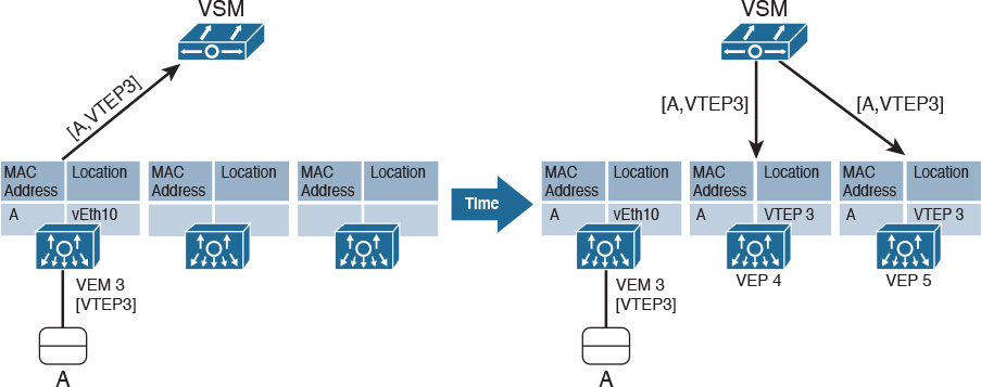
As explained earlier in the section “Standard VXLAN Deployment in Cisco Nexus 1000V,” each VEM has a VTEP and deploys a separate MAC address table. The left side of Figure 6-20 displays the moment VM A is connected to VXLAN 10000 on VEM 3. As a consequence, the active VSM learns that the VM MAC address can be reached through the VEM VTEP. Acting as a MAC-VTEP entry distributor, the VSM populates the MAC address table on other VEMs, as shown on the right side of Figure 6-20.
Furthermore, Example 6-6 describes how exactly an Enhanced VXLAN is configured on Nexus 1000V.
Example 6-6 Enhanced VXLAN Deployment
! Creating an Enhanced VXLAN
vsm(config)# bridge-domain VXLAN10000
vsm(config-bd)# segment id 10000
vsm(config-bd)# segment mode unicast-only
! Creating a vEthernet port profile assigned to bridge domain "VXLAN10000"
vsm(config-bd)# port-profile type vethernet VM-10000
vsm(config-pp)# switchport mode access
vsm(config-pp)# switchport access bridge-domain VXLAN10000
vsm(config-pp)# no shutdown
vsm(config-pp)# vmware port-group
vsm(config-pp)# state enabled
vsm(config-pp)#
In Example 6-6, rather than defining a multicast group for the bridge domain, I have used the segment mode unicast-only command to create bridge domain “VXLAN10000.” Afterward, I have assigned the bridge domain to port profile VM-10000, auto-generating a connectivity policy (Port Group in VMware vSphere) that may be associated to virtual network adapters on VMs.
Note
The same Nexus 1000V instance can simultaneously deploy standard and Enhanced VXLAN segments.
As an immediate effect from this method, the flooding of frames with unknown destination MAC addresses is no longer necessary. Because the VSM can distribute MAC addresses from an Enhanced VXLAN among all of its VEMs, there is full awareness of all MAC addresses in that segment—put simply, there are no unknown addresses.
Yet, broadcast messages are still necessary in IP-based communications within a VXLAN segment (for example, ARP messages). So how are broadcast frames forwarded in Enhanced VXLAN segments? The answer lies in Figure 6-21.
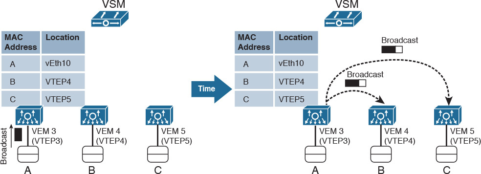
On the left side of Figure 6-21, VM A sends a broadcast frame, which, of course, should be received by all other VMs connected to Enhanced VXLAN 10000. Because the active VSM has already populated the all VEMs’ MAC address tables, VEM 3 is aware of the virtual machines that are connected to the same VXLAN (VM B in VEM 4 and VM C in VEM 5). Thus, VEM 3 performs a head-end replication of the VXLAN packet that contains the broadcast frame, sending one copy to each VTEP registered in its MAC address table.
Note
In the case of standard VXLAN, the multicast IP network takes care of the packet replication in the case of multidestination packets.
Controller-based unicast-only VXLANs are obviously limited to the controller domain. In the case of Nexus 1000V, an active VSM can populate only the MAC address tables of its administered VEMs. Under these circumstances, Cisco and other vendors have initiated some endeavors to standardize unicast-only VXLAN communication between independent VTEPs. Among many efforts, one is apparently becoming a de facto standard at the time of this writing: VXLAN Ethernet Virtual Private Network (EVPN).
The secret sauce of this technology is the use of Multiprotocol Border Gateway Protocol (MP-BGP) to exchange MAC-VTEP entries between multiple devices deploying VXLAN segments. With this approach, all VTEPs (physical or virtual) signal a new VXLAN-attached host through MP-BGP updates to other VTEPs.
In fairly large VXLAN networks, with multiple VTEPs, it may become extremely complex to manage the full-mesh set of MP-BGP connections between all VTEPs on a network. Instead, a BGP route reflector can be deployed as a central point of advertisement, where one MAC-VTEP update from a VXLAN segment that is sent to the route reflector will subsequently be forwarded to all other VTEPs deploying the same segment.
Further Reading
![]() Enhanced VXLAN on Cisco Nexus 1000V Switch for VMware vSphere Deployment Guide: http://www.cisco.com/c/en/us/products/collateral/switches/nexus-7000-series-switches/guide_c07-728863.html
Enhanced VXLAN on Cisco Nexus 1000V Switch for VMware vSphere Deployment Guide: http://www.cisco.com/c/en/us/products/collateral/switches/nexus-7000-series-switches/guide_c07-728863.html
![]() VXLAN DCI Using EVPN: http://tools.ietf.org/id/draft-boutros-l2vpn-vxlan-evpn-04.txt
VXLAN DCI Using EVPN: http://tools.ietf.org/id/draft-boutros-l2vpn-vxlan-evpn-04.txt
![]() Cisco Border Gateway Protocol Control Plane for Virtual Extensible LAN: http://www.cisco.com/c/en/us/products/collateral/switches/nexus-9000-series-switches/white-paper-c11-733737.html
Cisco Border Gateway Protocol Control Plane for Virtual Extensible LAN: http://www.cisco.com/c/en/us/products/collateral/switches/nexus-9000-series-switches/white-paper-c11-733737.html
Exam Preparation Tasks
Review All the Key Topics
Review the most important topics in this chapter, denoted with a Key Topic icon in the outer margin of the page. Table 6-5 lists a reference of these key topics and the page number on which each is found.
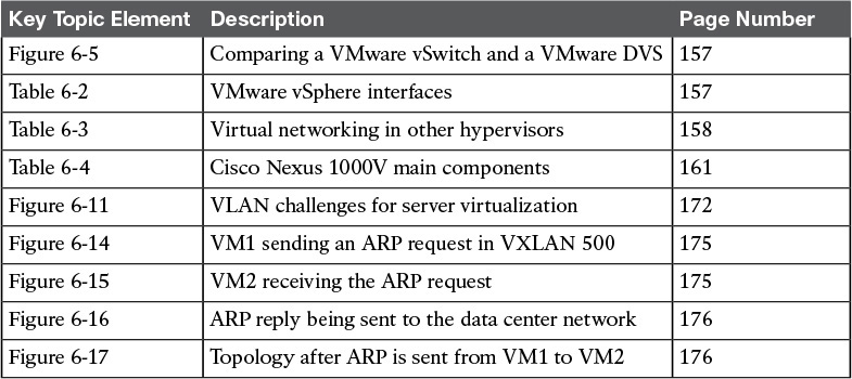
Table 6-5 Key Topics for Chapter 6
Complete the Tables and Lists from Memory
Print a copy of Appendix B, “Memory Tables” (found on the CD), or at least the section for this chapter, and complete the tables and lists from memory. Appendix C, “Answers to Memory Tables,” also on the CD, includes completed tables and lists so that you can check your work.
Define Key Terms
Define the following key terms from this chapter, and check your answers in the glossary:
distributed virtual switch (DVS)
Virtual Supervisor Module (VSM)
Virtual eXtensible LAN (VXLAN)