Chapter 9
IP Routing
The following topics are covered in this chapter:
- Describing the Packet Delivery Process
- Layer 1 Devices and Their Function
- Layer 2 Devices and Their Function
- Layer 2 Addressing
- Layer 3 Devices and Their Function
- Layer 3 Addressing
- Mapping Layer 2 Addressing to Layer 3 Addressing
- ARP Table
- Host-to-Host Packet Delivery
- Function of the Default Gateway
- Using Common Host Tools to Determine the Path Between Two Hosts Across a Network
In this chapter, I’m going to discuss the IP routing process. This is an important subject to understand since it pertains to all routers and configurations that use IP. IP routing is the process of moving packets from one network to another network using routers. And as before, by routers I mean Cisco routers, of course! However, we are going to use two different devices in this chapter—an IOS router and a Nexus switch with layer 3 capability. Both devices I’ll just refer to as a router because we are, well, routing in this chapter by using both devices in the same manner.
But before you read this chapter, you must understand the difference between a routing protocol and a routed protocol. A routing protocol is used by routers to dynamically find all the networks in the internetwork and to ensure that all routers have the same routing table. Basically, a routing protocol determines the path of a packet through an internetwork. Examples of routing protocols are RIP, RIPv2, EIGRP, and OSPF.
Once all routers know about all networks, a routed protocol can be used to send user data (packets) through the established enterprise. Routed protocols are assigned to an interface and determine the method of packet delivery. Examples of routed protocols are IP and IPv6.
I’m pretty sure that I don’t have to tell you that this is definitely important stuff to know. You most likely understand from what I’ve said so far that IP routing is basically what Cisco routers do, and they do it very well. Again, this chapter is dealing with truly fundamental material—these are things you must know if you want to understand the objectives covered in this book!
In Chapter 10, “Routing Protocols,” I’ll be moving into dynamic routing with RIP, EIGRP, and OSPF. But first, you’ve really got to nail down the basics of how packets actually move through an internetwork using routers, so let’s get started!
Routing Basics
Once you create an internetwork by connecting your networks to a router, you’ll need to configure logical network addresses, such as IP addresses, to all hosts on the internetwork so that they can communicate across that internetwork.
The term routing is used for taking a packet from one device and sending it through the network to another device on a different network. Routers don’t really care about hosts—they only care about networks and the best path to each network. The logical network address of the destination host is used to get packets to a network through a routed network, and then the hardware address of the host is used to deliver the packet from a router to the correct destination host.
If your network has no routers, then it should be apparent that you are not routing. Routers route traffic to all the networks in your internetwork. To be able to route packets, a router must know, at a minimum, the following:
- Destination address
- Neighbor routers from which it can learn about remote networks
- Possible routes to all remote networks
- The best route to each remote network
- How to maintain and verify routing information
The router learns about remote networks from neighbor routers or from an administrator. The router then builds a routing table (a map of the internetwork) that describes how to find the remote networks. If a network is directly connected, then the router already knows how to get to it.
If a network isn’t directly connected to the router, the router must use one of two ways to learn how to get to the remote network: static routing, meaning that someone must hand-type all network locations into the routing table, or something called dynamic routing.
In dynamic routing, a protocol on one router communicates with the same protocol running on neighbor routers. The routers then update each other about all the networks they know about and place this information into the routing table. If a change occurs in the network, the dynamic routing protocols automatically inform all routers about the event. If static routing is used, the administrator is responsible for updating all changes by hand into all routers. Typically, in a large network, a combination of both dynamic and static routing is used.
Before we jump into the IP routing process, let’s take a look at a very simple example that demonstrates how a router uses the routing table to route packets out of an interface. We’ll be going into a more detailed study of the process in the next section, but what I am showing now is called the “longest match rule,” which means that IP will look through a routing table for the longest match compared to the destination address of a packet. Let’s take a look.
Figure 9-1 shows a simple network. Lab_A has four LAN interfaces. Looking at Figure 9-1, can you see which interface you will use to forward an IP datagram to a host with a destination IP address of 10.10.10.30?
Figure 9-1: A simple routing example

By using the command show ip route on an IOS router we can see the routing table (map of the internetwork) that Lab_A uses to make forwarding decisions:
Lab_A#sh ip route
[output cut]
Gateway of last resort is not set
     10.0.0.0/8 is variably subnetted, 3 subnets, 3 masks
S       10.0.0.0/8 is directly connected, FastEthernet0/3
S       10.10.0.0/16 is directly connected, FastEthernet0/2
S       10.10.10.0/24 is directly connected, FastEthernet0/1
S*      0.0.0.0/0 is directly connected, FastEthernet0/0
The S in the routing table output means that the networks listed are “statically configured, or administratively configured,” and until we add a routing protocol—something like RIP or EIGRP—to the routers in our internetwork, by default we’d have only directly connected networks in our routing table, but in this example four static routes have been configured.
So let’s get back to the original question: By looking at the figure and the output of the routing table, can you tell what IP will do with a received packet that has a destination IP address of 10.10.10.30? Well, the answer is that the router will packet-switch the packet to interface FastEthernet 0/1, and this interface will frame the packet and then send it out on the network segment. To reiterate on the longest match rule, IP would look for the destination address 10.10.10.30, and in this example, the packet would match four entries in the output, but IP would use the longest match, which means both IP address and mask, and /24 (f0/1) is the longest match.
Because we can, let’s compare the IOS routing table output to a Nexus 7000 output with a similar basic configuration. First we’ll configure the 10/100/1000 Ethernet card in slot 3 of the Nexus 7000 with four connections; then we’ll display the routing table and discuss it.
Nexus7000# config
Enter configuration commands, one per line.  End with CNTL/Z.
Nexus7000(config)# int e3/1
Nexus7000(config-if)# no switchport
Nexus7000(config-if)# ip address 10.10.10.1 255.255.255.252
Nexus7000(config-if)# no shut
Nexus7000(config-if)# int e3/2
Nexus7000(config-if)# no switchport
Nexus7000(config-if)# ip address 10.10.10.17 255.255.255.240
Nexus7000(config-if)# no shut
Nexus7000(config-if)# int e3/3
Nexus7000(config-if)# no switchport
Nexus7000(config-if)# ip address 10.10.10.66 255.255.255.192
Nexus7000(config-if)# no shut
Nexus7000(config-if)# int e3/4
Nexus7000(config-if)# no switchport
Nexus7000(config-if)# ip address 10.10.1.1 255.255.255.0
Nexus7000(config-if)# no shut
Nexus7000(config-if)# sh ip route
IP Route Table for VRF "default"
'*' denotes best ucast next-hop
'**' denotes best mcast next-hop
'[x/y]' denotes [preference/metric]
10.10.1.0/24, ubest/mbest: 1/0, attached
    *via 10.10.1.1, Eth3/4, [0/0], 00:00:21, direct
10.10.1.1/32, ubest/mbest: 1/0, attached
    *via 10.10.1.1, Eth3/4, [0/0], 00:00:21, local
10.10.10.0/30, ubest/mbest: 1/0, attached
    *via 10.10.10.1, Eth3/1, [0/0], 00:05:16, direct
10.10.10.1/32, ubest/mbest: 1/0, attached
    *via 10.10.10.1, Eth3/1, [0/0], 00:05:16, local
10.10.10.16/28, ubest/mbest: 1/0, attached
    *via 10.10.10.17, Eth3/2, [0/0], 00:04:55, direct
10.10.10.17/32, ubest/mbest: 1/0, attached
    *via 10.10.10.17, Eth3/2, [0/0], 00:04:55, local
10.10.10.64/26, ubest/mbest: 1/0, attached
    *via 10.10.10.66, Eth3/3, [0/0], 00:00:15, direct
10.10.10.66/32, ubest/mbest: 1/0, attached
    *via 10.10.10.66, Eth3/3, [0/0], 00:00:15, local
Now that’s a different routing table! If you’re used to IOS, which most of us are, this is a much different output! However, once you spend some time studying this, you’ll get the hang of it. Basically it is the same thing (routing is routing), but it is just displayed differently and one destination network uses four lines in the table. This is easier to understand if I try and display the output on two lines instead of four using the e3/3 interface as an example, but the lines will still wrap because of the length limitation of the book:
10.10.10.64/26, ubest/mbest: 1/0, attached*via 10.10.10.66, Eth3/3,
[0/0], 00:00:15, direct
10.10.10.66/32, ubest/mbest: 1/0, attached*via 10.10.10.66, Eth3/3,
[0/0], 00:00:15, local
First, you see the attached connected subnet 10.10.10.64/26, via the exit_ip_address/exit interface. Pretty much the same as an IOS output.
However, what they have listed next in this output, which is not in an IOS output, is the actual interface IP address, listed as local, in the routing table. When this IP address is the destination IP address of a packet, IP will then parse the routing table and see that this is a locally attached IP address and not forward it out to the interface, e3/3 in this example.
One last thing that is also new. The ubest/mbest:1/0 is the unicast next-hop and multicast next-hop for the listed network. Notice the 1/0, attached *via. This is telling us that there is a single unicast address considered the best next-hop. If there were two routes that were equal to the remote network destination address, then the output would display 2/0. Don’t confuse this with the administrative distance/metric—it is not! Administrative distance/metric is covered in the next chapter.
Let’s get into this process in more detail.
The IP Routing Process
The IP routing process is fairly simple and doesn’t change, regardless of the size of your network. For an example, we’ll use Figure 9-2 to describe step-by-step what happens when Host_A wants to communicate with Host_B on a different network.
Figure 9-2: IP routing example using two hosts and one router

In this example, a user on Host_A pings Host_B’s IP address. Routing doesn’t get simpler than this, but it still involves a lot of steps. Let’s work through them:
- If it has, the packet is then free to be handed to the Data Link layer for framing. (The hardware destination address is also handed down with that packet.) To view the ARP cache on your host, use the following command:
C:>arp -a
Interface: 172.16.10.2 --- 0x3
  Internet Address      Physical Address      Type
172.16.10.1 00-15-05-06-31-b0 dynamic- If the hardware address isn’t already in the ARP cache of the host, an ARP broadcast is sent out onto the local network to search for the hardware address of 172.16.10.1. The router responds to the request and provides the hardware address of Ethernet 3/1, and the host caches this address.
Figure 9-3: Frame used from Host_A to the Lab_A router when Host_B is pinged

- If the CRC matches, then the hardware destination address is checked to see if it matches too (which, in this example, is the router’s interface Ethernet 3/1).
- If it’s a match, then the Ether-Type field is checked to find the protocol used at the Network layer.
Nexus7K(config-if)# show ip route
[output cut]
172.16.10.0/24, ubest/mbest: 1/0, attached
    *via 172.16.10.1, Eth3/1, [0/0], 01:15:59, direct
172.16.10.1/32, ubest/mbest: 1/0, attached
    *via 172.16.10.1, Eth3/1, [0/0], 01:15:59, local
172.16.20.0/24, ubest/mbest: 1/0, attached
    *via 172.16.20.1, Eth3/2, [0/0], 00:00:19, direct
172.16.20.1/32, ubest/mbest: 1/0, attached
*via 172.16.20.1, Eth3/2, [0/0], 00:00:19, local- If the hardware address of Host_B has already been resolved and is in the router’s ARP cache, then the packet and the hardware address are handed down to the Data Link layer to be framed. Let’s take a look at the ARP cache on the Lab_A router by using the show ip arp command:
Nexus7K(config-if)# sh ip arp
IP ARP Table for context default
Total number of entries: 6
Address         Age       MAC Address     Interface
172.16.10.2     00:14:47  0013.1937.e978  Ethernet3/1
172.16.20.2 00:14:40 0015.f9b6.c8a8 Ethernet3/2- If the hardware address has not already been resolved, the router sends an ARP request to E3/2 looking for the hardware address of 172.16.20.2. Host_B responds with its hardware address, and the packet and destination hardware addresses are both sent to the Data Link layer for framing.
- The destination and source hardware addresses
- The Ether-Type field with 0x0800 (IP) in it
- The FCS field with the CRC result in tow

You’ve just experienced Todd’s 36 easy steps to understanding IP routing. The key point to understand here is that if you had a much larger network, the process would be the same. In a really big internetwork, the packet just goes through more hoops before it finds the destination host.
It’s super-important to remember that when Host_A sends a packet to Host_B, the destination hardware address used is the default gateway’s Ethernet interface. Why? Because frames can’t be placed on remote networks—only local networks. So packets destined for remote networks must go through the default gateway.
Let’s take a look at Host_A’s ARP cache now:
C: >arp -a
Interface: 172.16.10.2 --- 0x3
  Internet Address      Physical Address      Type
  172.16.10.1           00-15-05-06-31-b0     dynamic
  172.16.20.1           00-15-05-06-31-b0     dynamic
Did you notice that the hardware (MAC) address that Host_A uses to get to Host_B is the Lab_A E3/1 interface? Hardware addresses are always local, and they never pass a router’s interface. Understanding this process is as important as air to you, so carve this into your memory!
Testing Your IP Routing Understanding
I really want to make sure you understand IP routing because it’s super-important. So I’m going to use this section to test your understanding of the IP routing process by having you look at a couple of figures and answer some very basic IP routing questions.
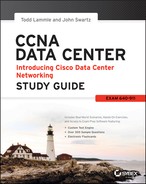
Figure 9-4 shows a LAN connected to RouterA, which is, in turn, connected via a WAN link to RouterB. RouterB has a LAN connected with an HTTP server attached.
Figure 9-4: IP routing example 1
The critical information you need to glean from this figure is exactly how IP routing will occur in this example. Okay—we’ll cheat a bit. I’ll give you the answer, but then you should go back over the figure and see if you can answer example 2 without looking at my answers.
That example was a pretty simple one, and it was also very to the point. One thing to remember is that if multiple hosts are communicating to the server using HTTP, they must all use a different source port number. That is how the server keeps the data separated at the Transport layer.
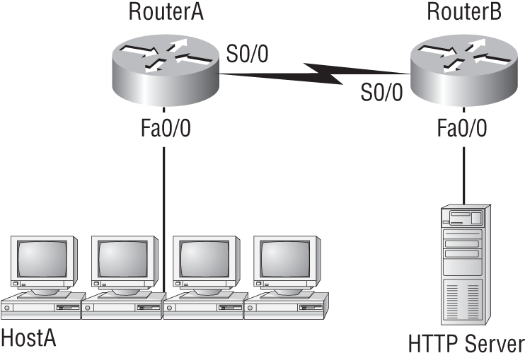
Let’s mix it up a little and add another internetworking device into the network and then see if you can find the answers. Figure 9-5 shows a network with only one router but two switches.
Figure 9-5: IP routing example 2
What you want to understand about the IP routing process here is what happens when HostA sends data to the HTTPS server:
Notice that the switches weren’t used as either a default gateway or another destination. That’s because switches have nothing to do with routing. I wonder how many of you chose the switch as the default gateway (destination) MAC address for HostA? If you did, don’t feel bad—just take another look with that fact in mind. It’s very important to remember that the destination MAC address will always be the router’s interface—if your packets are destined for outside the LAN, as they were in these last two examples.
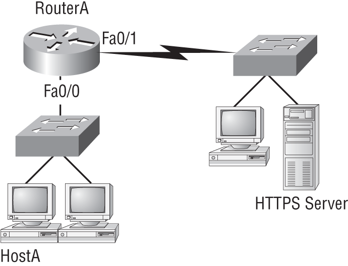
Before we move into some of the more advanced aspects of IP routing, let’s discuss ICMP in more detail, as well as how ICMP is used in an internetwork. Take a look at the network shown in Figure 9-6. Ask yourself what will happen if the LAN interface of router Lab_C goes down.
Figure 9-6: ICMP error example
Lab_C will use ICMP to inform Host A that Host B can’t be reached, and it will do this by sending an ICMP destination unreachable message. The point of this figure is to help you visualize how ICMP data is routed via IP back to the originating station.
Let’s look at another problem. Look at the output of a corporate router’s IOS routing table:
Corp#sh ip route
[output cut]
R    192.168.215.0 [120/2] via 192.168.20.2, 00:00:23, Serial0/0
R    192.168.115.0 [120/1] via 192.168.20.2, 00:00:23, Serial0/0
R    192.168.30.0 [120/1] via 192.168.20.2, 00:00:23, Serial0/0
C    192.168.20.0 is directly connected, Serial0/0
C    192.168.214.0 is directly connected, FastEthernet0/0
What do we see here? If I were to tell you that the corporate router received an IP packet with a source IP address of 192.168.214.20 and a destination address of 192.168.22.3, what do you think the Corp router will do with this packet?
If you said, “The packet came in on the FastEthernet 0/0 interface, but since the routing table doesn’t show a route to network 192.168.22.0 (or a default route), the router will discard the packet and send an ICMP destination unreachable message back out interface FastEthernet 0/0,” you’re a genius! The reason it does this is because that’s the source LAN from which the packet originated.
Now, let’s check out another figure and talk about the frames and packets in detail. Really, we’re not exactly chatting about anything new; we’re just making sure that you totally, completely, fully understand basic IP routing. That’s because this book, and the exam objectives it’s geared toward, are all about IP routing, which means you need to be all over this stuff! We’ll use Figure 9-7 for the next few questions.
Figure 9-7: Basic IP routing using MAC and IP addresses

Referring to Figure 9-7, here’s a list of all the questions you need the answers to emblazoned in your brain:
The following should probably be written in a teensy font and put upside down in another part of the book so it would be really hard for you to cheat and peek, but since it’s actually you who’s going to lose out if you peek, here are your answers:
Great! But we’re not quite done yet. I’ve got a few more questions for you before you actually get to configure routing in a real network. Ready? Figure 9-8 shows a basic network, and Host 4 needs to get email. Which address will be placed in the destination address field of the frame when it leaves Host 4?
The answer is that Host 4 will use the destination MAC address of the Fa0/0 interface of the Lab_B router—which I’m so sure you knew, right? Look at Figure 9-8 again: Host 4 needs to communicate with Host 1. Which OSI layer 3 source address will be placed in the packet header when it reaches Host 1?
Hopefully you know this: At layer 3, the source IP address will be Host 4 and the destination address in the packet will be the IP address of Host 1. Of course, the destination MAC address from Host 4 will always be the Fa0/0 address of the Lab_B router, right? And since we have more than one router, we’ll need a routing protocol that communicates between both of them so that traffic can be forwarded in the right direction to reach the network in which Host 1 is attached.
Figure 9-8: Testing basic routing knowledge

Okay—one more question and you’re on your way to being an IP routing genius! Again, using Figure 9-8, Host 4 is transferring a file to the email server connected to the Lab_A router. What would be the layer 2 destination address leaving Host 4? Yes, I’ve asked this question more than once. But not this one: What will be the source MAC address when the frame is received at the email server?
Hopefully, you answered that the layer 2 destination address leaving Host 4 will be the MAC address of the Fa0/0 interface of the Lab_B router and that the source layer 2 address that the email server will receive will be the Fa0/0 interface of the Lab_A router.
If you did, you’re all set to get the skinny on how IP routing is handled in a larger network.
Summary
This chapter covered IP routing in detail. It’s extremely important that you really understand the basics we covered in this chapter because everything that’s done on a Nexus switch typically will have some type of IP routing configured and running.
You learned in this chapter how IP routing uses frames to transport packets between routers and to the destination host.
In the next chapter, we’ll continue on with dynamic routing protocols.
Exam Essentials
Written Lab 9
You can find the answers in Appendix A.
Write the answers to the following questions:
Review Questions
You can find the answers in Appendix B.
1. What destination addresses will be used by HostA to send data to the HTTPS server as shown in the following network? (Choose two.)

A. The IP address of the switch
B. The MAC address of the remote switch
C. The IP address of the HTTPS server
D. The MAC address of the HTTPS server
E. The IP address of RouterA’s Fa0/0 interface
F. The MAC address of RouterA’s Fa0/0 interface
2. Which of the following would be true if HostA is trying to communicate to HostB and the interface F0/0 of RouterC goes down, as shown in the following graphic? (Choose two.)
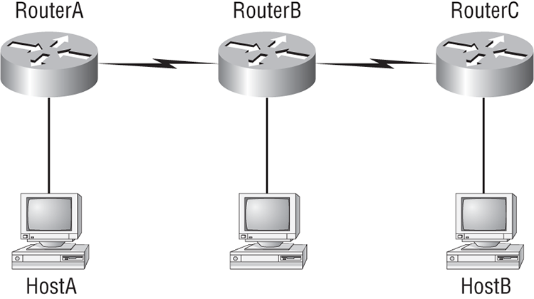
A. RouterC will use an ICMP to inform HostA that HostB cannot be reached.
B. RouterC will use ICMP to inform RouterB that HostB cannot be reached.
C. RouterC will use ICMP to inform HostA, RouterA, and RouterB that HostB cannot be reached.
D. RouterC will send a destination unreachable message type.
E. RouterC will send a router selection message type.
F. RouterC will send a source quench message type.
3. What addresses change at each hop a packet takes?
A. IP addresses
B. Port numbers
C. Layer 2 addresses
D. Segments
4. Your router receives a packet with a destination IP address not found in the routing table. What will the IP do with this packet?
A. Broadcast it out all interfaces.
B. Flood it out all interfaces except the one it was received on.
C. Discard the packet and send an ICMP error message back out the interface it was received on.
D. Discard the packet and send an ICMP error message back out the interface it was destined for.
5. If your host has a packet destined for a remote network, what local address will your host look for?
A. The IP address of the closest server
B. The IP address of the default gateway
C. The IP address of the closest server
D. The MAC address of the default gateway
6. What protocols will the IP use when you ping a local address from your host? (Choose two.)
A. TCP
B. IP
C. ARP
D. ICMP
7. To be able to route a packet, which at a minimum does your router need to know? (Choose two.)
A. The destination address
B. The source address
C. The possible routes to each network
D. The port number in the segment header
8. When two hosts are trying to communicate across a network, how does the host originating the communication determine the hardware address of the host that it wants to communicate to?
A. RARP request
B. Show Network Address request
C. Proxy ARP request
D. ARP request
E. Show Hardware Address request
9. An administrator attempts a traceroute but receives destination unreachable message. Which protocol is responsible for that message?
A. RARP
B. RUDP
C. ICMP
D. SNMP
10. To be able to route a packet, which of the following does your router need to know? (Choose two.)
A. The location of neighbor routers
B. The hardware address of the remote router
C. How to maintain and verify routing information
D. The application being used and VLAN information