Chapter 4
TCP/IP DoD Model
The following topics Are covered in this chapter:
- Describing the TCP/IP Transport Layer
- Transport Layer Functions
- Reliable vs. Best–Effort
- UDP Characteristics
- TCP Characteristics
- TCP/IP Applications
- Mapping Layer 3 to Layer 4
- Mapping Layer 4 to Applications
- Establishing a Connection with a Peer System
- Flow Control
- TCP Acknowledgment
- Windowing
- TCP Sequence Number and Acknowledgment Numbers
The Transmission Control Protocol/Internet Protocol (TCP/IP) suite was created by the Department of Defense (DoD) to ensure and preserve data integrity as well as maintain communications in the event of catastrophic war. So it follows that if designed and implemented correctly, a TCP/IP network can be a truly dependable and resilient one. In this chapter, I’ll cover the protocols of TCP/IP, and throughout this book, you’ll learn how to create a marvelous TCP/IP network—using Cisco Nexus switches and IOS routers, of course.
We’ll begin by taking a look at the DoD’s version of TCP/IP and then compare this version and its protocols with the OSI reference model discussed in Chapter 2, “Internetworking.”
Introducing TCP/IP
Because TCP/IP is so central to working with the Internet and intranets, it’s essential for you to understand it in detail. I’ll begin by giving you some background on TCP/IP and how it came about and then move on to describing the important technical goals defined by the original designers. After that, you’ll find out how TCP/IP compares to a theoretical model—the Open Systems Interconnection (OSI) model.
A Brief History of TCP/IP
TCP/IP first came on the scene in 1973. Later, in 1978, it was divided into two distinct protocols: TCP and IP. Then, in 1983, TCP/IP replaced the Network Control Protocol (NCP) and was authorized as the official means of data transport for anything connecting to ARPAnet, the Internet’s ancestor that was created by ARPA, the DoD’s Advanced Research Projects Agency, way back in 1957 in reaction to the Soviet’s launching of Sputnik. ARPA was soon redubbed DARPA, and it was divided into ARPAnet and MILNET (also in 1983); both were finally dissolved in 1990.
But contrary to what you might think, most of the development work on TCP/IP happened at UC Berkeley in Northern California, where a group of scientists were simultaneously working on the Berkeley version of UNIX, which soon became known as the BSD, or Berkeley Software Distribution, series of Unix versions. Of course, because TCP/IP worked so well, it was packaged into subsequent releases of BSD UNIX and offered to other universities and institutions if they bought the distribution tape. So basically, BSD Unix bundled with TCP/IP began as shareware in the world of academia and, as a result, became the basis of the huge success and exponential growth of today’s Internet as well as smaller, private and corporate intranets.
As usual, what may have started as a small group of TCP/IP aficionados evolved, and as it did, the US government created a program to test any new published standards and make sure they passed certain criteria. This was to protect TCP/IP’s integrity and to ensure that no developer changed anything too dramatically or added any proprietary features. It’s this very quality—this open-systems approach to the TCP/IP family of protocols—that pretty much sealed its popularity because it guarantees a solid connection between myriad hardware and software platforms with no strings attached.
TCP/IP and the DoD Model
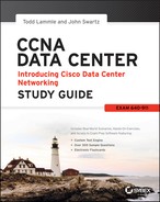
The DoD model is basically a condensed version of the OSI model—it’s composed of four, instead of seven, layers:
- Process/Application layer
- Host-to-Host layer
- Internet layer
- Network Access layer
Figure 4-1 shows a comparison of the DoD model and the OSI reference model. As you can see, the two are similar in concept, but each has a different number of layers with different names.
Figure 4-1: The DoD and OSI models

A vast array of protocols combine at the DoD model’s Process/Application layer to integrate the various activities and duties spanning the focus of the OSI’s corresponding top three layers (Application, Presentation, and Session). We’ll be looking closely at those protocols in the next part of this chapter. The Process/Application layer defines protocols for node-to-node application communication and also controls user-interface specifications.
The Host-to-Host layer parallels the functions of the OSI’s Transport layer, defining protocols for setting up the level of transmission service for applications. It tackles issues such as creating reliable end-to-end communication and ensuring the error-free delivery of data. It handles packet sequencing and maintains data integrity.
The Internet layer corresponds to the OSI’s Network layer, designating the protocols relating to the logical transmission of packets over the entire network. It takes care of the addressing of hosts by giving them an IP (Internet Protocol) address, and it handles the routing of packets among multiple networks.
At the bottom of the DoD model, the Network Access layer implements the data exchange between the host and the network. The equivalent of the Data Link and Physical layers of the OSI model, the Network Access layer oversees hardware addressing and defines protocols for the physical transmission of data.
The DoD and OSI models are alike in design and concept and have similar functions in similar layers. Figure 4-2 shows the TCP/IP protocol suite and how its protocols relate to the DoD model layers.
Figure 4-2: The TCP/IP protocol suite
In the following sections, we will look at the different protocols in more detail, starting with the Process/Application layer protocols.
The Process/Application Layer Protocols
In the following sections, I’ll describe the different applications and services typically used in IP networks. The following protocols and applications are covered:
- Telnet
- FTP
- TFTP
- NFS
- SMTP
- POP
- SNMP
- SSH
- HTTP
- HTTPS
- NTP
- DNS
- DHCP/BootP
Telnet
Telnet is the chameleon of protocols—its specialty is terminal emulation. It allows a user on a remote client machine, called the Telnet client, to access the resources of another machine, the Telnet server. Telnet achieves this by pulling a fast one on the Telnet server and making the client machine appears as though it were a terminal directly attached to the local network. This projection is actually a software image—a virtual terminal that can interact with the chosen remote host.
These emulated terminals are of the text-mode type and can execute defined procedures such as displaying menus that give users the opportunity to choose options and access the applications on the duped server. Users begin a Telnet session by running the Telnet client software and then logging into the Telnet server.
File Transfer Protocol (FTP)
File Transfer Protocol (FTP) is the protocol that actually lets us transfer files, and it can accomplish this between any two machines using it. But FTP isn’t just a protocol; it’s also a program. Operating as a protocol, FTP is used by applications. As a program, it’s employed by users to perform file tasks by hand. FTP also allows for access to both directories and files and can accomplish certain types of directory operations, such as relocating into different ones.
Accessing a host through FTP is only the first step, though. Users must then be subjected to an authentication login that’s probably secured with passwords and usernames implemented by system administrators to restrict access. You can get around this somewhat by adopting the username anonymous—though what you’ll gain access to will be limited.
Even when employed by users manually as a program, FTP’s functions are limited to listing and manipulating directories, typing file contents, and copying files between hosts. It can’t execute remote files as programs.
Trivial File Transfer Protocol (TFTP)
Trivial File Transfer Protocol (TFTP) is the stripped-down, stock version of FTP, but it’s the protocol of choice if you know exactly what you want and where to find it, plus it’s so easy to use and it’s fast too! It doesn’t give you the abundance of functions that FTP does, though. TFTP has no directory-browsing abilities; it can do nothing but send and receive files. This compact little protocol also skimps in the data department, sending much smaller blocks of data than FTP, and there’s no authentication as with FTP, so it’s even more insecure. Few sites support it because of the inherent security risks.
Network File System (NFS)
Network File System (NFS) is a jewel of a protocol specializing in file sharing. It allows two different types of file systems to interoperate. It works like this: suppose the NFS server software is running on a Windows server and the NFS client software is running on a Unix host. NFS allows for a portion of the RAM on the Windows server to transparently store Unix files, which can, in turn, be used by Unix users. Even though the Windows file system and Unix file system are unlike—they have different case sensitivity, filename lengths, security, and so on—both Unix users and Windows users can access that same file with their normal file systems, in their normal way.
Simple Mail Transfer Protocol (SMTP)
Simple Mail Transfer Protocol (SMTP), answering our ubiquitous call to email, uses a spooled, or queued, method of mail delivery. Once a message has been sent to a destination, the message is spooled to a device—usually a disk. The server software at the destination posts a vigil, regularly checking the queue for messages. When it detects them, it proceeds to deliver them to their destination. SMTP is used to send mail; POP3 or IMAP is used to receive mail.
Post Office Protocol (POP)
Post Office Protocol (POP) gives us a storage facility for incoming mail, and the latest version is called POP3 (sound familiar?). Basically, how this protocol works is when a client device connects to a POP3 server, messages addressed to that client are released for downloading. It doesn’t allow messages to be downloaded selectively, but once they are, the client/server interaction ends and you can delete and tweak your messages locally at will. Lately we’re seeing a newer standard, IMAP, being used more and more in place of POP3.
Simple Network Management Protocol (SNMP)
Simple Network Management Protocol (SNMP) collects and manipulates valuable network information. It gathers data by polling the devices on the network from a management station at fixed or random intervals, requiring them to disclose certain information. When all is well, SNMP receives something called a baseline—a report delimiting the operational traits of a healthy network. This protocol can also stand as a watchdog over the network, quickly notifying managers of any sudden turn of events. These network watchdogs are called agents, and when aberrations occur, agents send an alert called a trap to the management station that contains information such as CPU or interface utilization, up/down status, thermal statistics, and more.
Secure Shell (SSH)
Secure Shell (SSH) protocol sets up a secure Telnet session over a standard TCP/IP connection and is employed for doing things like logging into systems, running programs on remote systems, and moving files from one system to another. And it does all of this while maintaining a nice, strong, encrypted connection. You can think of it as the new-generation protocol that’s now used in place of rsh and rlogin—even Telnet.
Hypertext Transfer Protocol (HTTP)
All those snappy websites comprising a mélange of graphics, text, links, and so on—the Hypertext Transfer Protocol (HTTP) is making it all possible. It’s used to manage communications between web browsers and web servers and opens the right resource when you click a link, wherever that resource may actually reside.
Hypertext Transfer Protocol Secure (HTTPS)
Hypertext Transfer Protocol Secure (HTTPS) is also known as Secure Hypertext Transfer Protocol. It uses Secure Sockets Layer (SSL). Sometimes you’ll see it referred to as SHTTP or S-HTTP (which is an extension of HTTP and doesn’t use SSL), but no matter—as indicated, it’s a secure version of HTTP that arms you with a whole bunch of security tools for keeping transactions between a web browser and a server secure. It’s what your browser needs to fill out forms, sign in, authenticate, and encrypt an HTTP message when you make a reservation or buy something online.
Network Time Protocol (NTP)
Kudos to Professor David Mills of the University of Delaware for coming up with this handy protocol that’s used to synchronize the clocks on our computers to one standard time source (typically, an atomic clock). Network Time Protocol (NTP) works by synchronizing devices to ensure that all computers on a given network agree on the time. This may sound pretty simple, but it’s very important because so many of the transactions done today are time- and date-stamped. Think about your precious databases, for one. It can mess up a server pretty badly if it’s out of sync with the machines connected to it, even by mere seconds (think crash!). You can’t have a transaction entered by a machine at, say, 1:50 a.m. when the server records that transaction as having occurred at 1:45 a.m. So basically, NTP works to prevent “back to the future sans DeLorean” from bringing down the network—very important indeed!
Domain Name Service (DNS)
Domain Name Service (DNS) resolves hostnames—specifically, Internet names, such as www.lammle.com. You don’t have to use DNS; you can just type in the IP address of any device you want to communicate with. An IP address identifies hosts on a network and the Internet as well. However, DNS was designed to make our lives easier. Think about this: what would happen if you wanted to move your web page to a different service provider? The IP address would change and no one would know what the new one was. DNS allows you to use a domain name to specify an IP address. You can change the IP address as often as you want and no one will know the difference.
DNS is used to resolve a fully qualified domain name (FQDN)—for example, www.lammle.com or todd.lammle.com. An FQDN is a hierarchy that can logically locate a system based on its domain identifier.
If you want to resolve the name todd, you either must type in the FQDN of todd.lammle.com or have a device such as a PC or router add the suffix for you. For example, on a Cisco router, you can use the command ipdomain-namelammle.com to append each request with the lammle.com domain. If you don’t do that, you’ll have to type in the FQDN to get DNS to resolve the name.

Dynamic Host Configuration Protocol (DHCP)/Bootstrap Protocol (BootP)
Dynamic Host Configuration Protocol (DHCP) assigns IP addresses to hosts. It allows easier administration and works well in small to even very large network environments. All types of hardware can be used as a DHCP server, including a Cisco router.
DHCP differs from BootP in that BootP assigns an IP address to a host but the host’s hardware address must be entered manually in a BootP table. You can think of DHCP as a dynamic BootP. But remember that BootP is also used to send an operating system that a host can boot from. DHCP can’t do that.
But there is a lot of information a DHCP server can provide to a host when the host is requesting an IP address from the DHCP server. Here’s a list of the information a DHCP server can provide:
- IP address
- Subnet mask
- Domain name
- Default gateway (routers)
- DNS server address
- WINS server address
A DHCP server can give us even more information than this, but the items in the list are the most common.
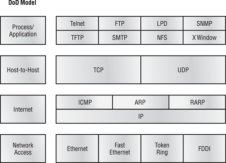
A client that sends out a DHCP Discover message in order to receive an IP address sends out a broadcast at both layer 2 and layer 3.
- The layer 2 broadcast is all Fs in hex, which looks like this: FF:FF:FF:FF:FF:FF.
- The layer 3 broadcast is 255.255.255.255, which means all networks and all hosts.
DHCP is connectionless, which means it uses User Datagram Protocol (UDP) at the Transport layer, also known as the Host-to-Host layer, which we’ll talk about next.
In case you don’t believe me, here’s an example of output from my trusty analyzer:
Ethernet II, Src: 0.0.0.0 (00:0b:db:99:d3:5e),Dst: Broadcast(ff:ff:ff:ff:ff:ff)
Internet Protocol, Src: 0.0.0.0 (0.0.0.0),Dst: 255.255.255.255(255.255.255.255)
The Data Link and Network layers are both sending out “all hands” broadcasts saying, “Help—I don’t know my IP address!”
Figure 4-3 shows the process of a client/server relationship using a DHCP connection.
Figure 4-3: DHCP client four-step process
The following is the four-step process a client takes to receive an IP address from a DHCP server:
DHCP Conflicts
A DHCP address conflict occurs when two hosts use the same IP address. This sounds bad, doesn’t it? Well of course it is!
During IP address assignment, a DHCP server checks for conflicts using the ping program to test the availability of the address before it is assigned from the pool. If no host replies, then the DHCP server assumes that the IP address is not already allocated. This helps the server know that it is providing a good address, but what about the host? To provide extra protection against the all-so-terrible IP conflict issue, the host can broadcast for its own address.
A host uses something called a gratuitous ARP to help avoid a possible duplicate address. The DHCP client sends an ARP broadcast out on the local LAN or VLAN using its newly assigned address to solve conflicts before they occur.
So, if an IP address conflict is detected, the address is removed from the DHCP pool (scope), and it is all-so-important to remember that the address will not be assigned to a host until the administrator resolves the conflict by hand.
Automatic Private IP Addressing (APIPA)
Okay, so what happens if you have a few hosts connected together with a switch or hub and you don’t have a DHCP server? You can add IP information by hand (this is called static IP addressing), but Windows provides what is called Automatic Private IP Addressing (APIPA), a feature of later Windows operating systems. With APIPA, clients can automatically self-configure an IP address and subnet mask (basic IP information that hosts use to communicate) when a DHCP server isn’t available. The IP address range for APIPA is 169.254.0.1 through 169.254.255.254. The client also configures itself with a default Class B subnet mask of 255.255.0.0.
However, when you’re in your corporate network working and you have a DHCP server running, and your host shows that it is using this IP address range, this means that either your DHCP client on the host is not working or the server is down or can’t be reached because of a network issue. I don’t know anyone who’s seen a host in this address range and has been happy about it!
Now, let’s take a look at the Transport layer, or what the DoD calls the Host-to-Host layer.
The Host-to-Host Layer Protocols
The main purpose of the Host-to-Host layer is to shield the upper-layer applications from the complexities of the network. This layer says to the upper layer, “Just give me your data stream, with any instructions, and I’ll begin the process of getting your information ready to send.”
The following sections describe the two protocols at this layer:
- Transmission Control Protocol (TCP)
- User Datagram Protocol (UDP)
In addition, we’ll look at some of the key host-to-host protocol concepts, as well as the port numbers.
Transmission Control Protocol (TCP)
Transmission Control Protocol (TCP) takes large blocks of information from an application and breaks them into segments. It numbers and sequences each segment so that the destination’s TCP stack can put the segments back into the order the application intended. After these segments are sent, TCP (on the transmitting host) waits for an acknowledgment of the receiving end’s TCP virtual circuit session, retransmitting those that aren’t acknowledged.
Before a transmitting host starts to send segments down the model, the sender’s TCP stack contacts the destination’s TCP stack to establish a connection. What is created is known as a virtual circuit. This type of communication is called connection-oriented. During this initial handshake, the two TCP layers also agree on the amount of information that’s going to be sent before the recipient’s TCP sends back an acknowledgment. With everything agreed upon in advance, the path is paved for reliable communication to take place.
TCP is a full-duplex, connection-oriented, reliable, and accurate protocol, but establishing all these terms and conditions, in addition to error checking, is no small task. TCP is very complicated and, not surprisingly, costly in terms of network overhead. And since today’s networks are much more reliable than those of yore, this added reliability is often unnecessary. Most programmers use TCP because it removes a lot of programming work; however, real-time video and VoIP use UDP because they can’t afford the overhead.
TCP Segment Format
Since the upper layers just send a data stream to the protocols in the Transport layers, I’ll demonstrate how TCP segments a data stream and prepares it for the Internet layer. When the Internet layer receives the data stream, it routes the segments as packets through an internetwork. The segments are handed to the receiving host’s Host-to-Host layer protocol, which rebuilds the data stream to hand to the upper-layer applications or protocols.
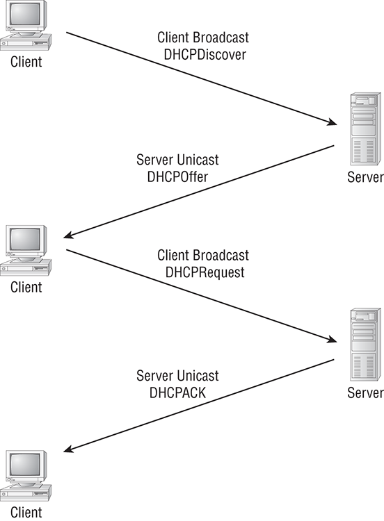
Figure 4-4 shows the TCP segment format. The figure shows the different fields within the TCP header.
Figure 4-4: TCP segment format
The TCP header is 20 bytes long, or up to 24 bytes with options. You need to understand what each field in the TCP segment is:
Let’s take a look at a TCP segment copied from a network analyzer:
TCP - Transport Control Protocol
 Source Port:      5973
 Destination Port: 23
 Sequence Number:  1456389907
 Ack Number:       1242056456
 Offset:           5
 Reserved:         %000000
 Code:             %011000
Ack is valid
      Push Request
 Window:           61320
 Checksum:         0x61a6
 Urgent Pointer:   0
 No TCP Options
 TCP Data Area:
 vL.5.+.5.+.5.+.5  76 4c 19 35 11 2b 19 35 11 2b 19 35 11
  2b 19 35 +. 11 2b 19
Frame Check Sequence: 0x0d00000f
Did you notice that everything I talked about earlier is in the segment? As you can see from the number of fields in the header, TCP creates a lot of overhead. Application developers may opt for efficiency over reliability to save overhead, so User Datagram Protocol was also defined at the Transport layer as an alternative.
User Datagram Protocol (UDP)
If you were to compare User Datagram Protocol (UDP) with TCP, the former is basically the scaled-down economy model that’s sometimes referred to as a thin protocol. Like a thin person on a park bench, a thin protocol doesn’t take up a lot of room—or in this case, much bandwidth on a network.
UDP doesn’t offer all the bells and whistles of TCP either, but it does do a fabulous job of transporting information that doesn’t require reliable delivery—and it does so using far fewer network resources. (UDP is covered thoroughly in Request for Comments 768.)
There are some situations in which it would definitely be wise for developers to opt for UDP rather than TCP. One circumstance is when reliability is already handled at the Process/Application layer. Network File System (NFS) handles its own reliability issues, making the use of TCP both impractical and redundant. But ultimately, it’s up to the application developer to decide whether to use UDP or TCP, not the user who wants to transfer data faster.
UDP does not sequence the segments and does not care in which order the segments arrive at the destination. But after that, UDP sends the segments off and forgets about them. It doesn’t follow through, check up on them, or even allow for an acknowledgment of safe arrival—complete abandonment. Because of this, it’s referred to as an unreliable protocol. This does not mean that UDP is ineffective, only that it doesn’t handle issues of reliability.
Further, UDP doesn’t create a virtual circuit, nor does it contact the destination before delivering information to it. Because of this, it’s also considered a connectionless protocol. Since UDP assumes that the application will use its own reliability method, it doesn’t use any. This gives an application developer a choice when running the Internet Protocol stack: TCP for reliability or UDP for faster transfers.
So, it is important to remember how this works because if the segments arrive out of order (very common in IP networks), they’ll just be passed up to the next OSI (DoD) layer in whatever order they’re received, possibly resulting in some seriously garbled data. On the other hand, TCP sequences the segments so they get put back together in exactly the right order—something UDP just can’t do.
UDP Segment Format
Figure 4-5 clearly illustrates UDP’s markedly low overhead as compared to TCP’s hungry usage. Look at the figure carefully—can you see that UDP doesn’t use windowing or provide for acknowledgments in the UDP header?
Figure 4-5: UDP segment
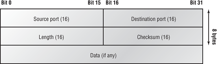
It’s important for you to understand what each field in the UDP segment is:
UDP, like TCP, doesn’t trust the lower layers and runs its own CRC.
The following shows a UDP segment caught on a network analyzer:
UDP - User Datagram Protocol
 Source Port:      1085
 Destination Port: 5136
 Length:           41
 Checksum:         0x7a3c
 UDP Data Area:
 ..Z......00 01 5a 96 00 01 00 00 00 00 00 11 0000 00
...C..2._C._C  2e 03 00 43 02 1e 32 0a 00 0a 00 80 43 00 80
Frame Check Sequence: 0x00000000
Notice that low overhead! Try to find the sequence number, ack number, and window size in the UDP segment. You can’t because they just aren’t there!
Key Concepts of Host-to-Host Protocols
Since you’ve seen both a connection-oriented (TCP) and connectionless (UDP) protocol in action, it would be good to summarize the two here. Table 4-1 highlights some of the key concepts that you should keep in mind regarding these two protocols. You should memorize this table.
Table 4-1: Key features of TCP and UDP
| TCP | UDP |
| Sequenced | Unsequenced |
| Reliable | Unreliable |
| Connection-oriented | Connectionless |
| Virtual circuit | Low overhead |
| Acknowledgments | No acknowledgment |
| Windowing flow control | No windowing or flow control of any type |
A telephone analogy could really help you understand how TCP works. Most of us know that before you speak to someone on a phone, you must first establish a connection with them—wherever they are. This is like a virtual circuit with the TCP protocol. If you were giving someone important information during your conversation, you might say, “You know?” or ask, “Did you get that?” Saying something like this is a lot like a TCP acknowledgment—it’s designed to get you verification. From time to time (especially on cell phones), people also ask, “Are you still there?” They end their conversations with a “Goodbye” of some kind, putting closure on the phone call. TCP also performs these types of functions.
Alternately, using UDP is like sending a postcard. To do that, you don’t need to contact the other party first. You simply write your message, address the postcard, and mail it. This is analogous to UDP’s connectionless orientation. Since the message on the postcard is probably not a matter of life or death, you don’t need an acknowledgment of its receipt. Similarly, UDP does not involve acknowledgments.
Let’s take a look at another figure, one that includes TCP, UDP, and the applications associated with each protocol, Figure 4-6 (in the next section).
Port Numbers
TCP and UDP must use port numbers to communicate with the upper layers because they’re what keep track of different conversations crossing the network simultaneously. Originating-source port numbers are dynamically assigned by the source host and will equal some number starting at 1024. 1023 and below are defined in RFC 3232 (or just see www.iana.org), which discusses what are called well-known port numbers.
Virtual circuits that don’t use an application with a well-known port number are assigned port numbers randomly from a specific range instead. These port numbers identify the source and destination application or process in the TCP segment.
Figure 4-6 illustrates how both TCP and UDP use port numbers.
Figure 4-6: Port numbers for TCP and UDP
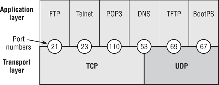
The different port numbers that can be used are explained next:
- Numbers below 1024 are considered well-known port numbers and are defined in RFC 3232.
- Numbers 1024 and above are used by the upper layers to set up sessions with other hosts and by TCP and UDP to use as source and destination addresses in the segment.
In the following sections, we’ll take a look at an analyzer output showing a TCP session.
TCP Session: Source Port
The following listing shows a TCP session captured with my analyzer software:
TCP - Transport Control Protocol
 Source Port:      5973
 Destination Port: 23
 Sequence Number:  1456389907
 Ack Number:       1242056456
 Offset:           5
 Reserved:         %000000
 Code:             %011000
      Ack is valid
      Push Request
 Window:           61320
 Checksum:         0x61a6
 Urgent Pointer:   0
 No TCP Options
 TCP Data Area:
 vL.5.+.5.+.5.+.5  76 4c 19 35 11 2b 19 35 11 2b 19 35 11
  2b 19 35 +. 11 2b 19
Frame Check Sequence: 0x0d00000f
Notice that the source host makes up the source port, which in this case is 5973. The destination port is 23, which is used to tell the receiving host the purpose of the intended connection (Telnet).
By looking at this session, you can see that the source host makes up the source port by using numbers from 1024 to 65535. But why does the source make up a port number? To differentiate between sessions with different hosts, my friend. How would a server know where information is coming from if it didn’t have a different number from a sending host? TCP and the upper layers don’t use hardware and logical addresses to understand the sending host’s address as the Data Link and Network layer protocols do. Instead, they use port numbers.
TCP Session: Destination Port
You’ll sometimes look at an analyzer and see that only the source port is above 1024 and the destination port is a well-known port, as shown in the following trace:
TCP - Transport Control Protocol
 Source Port:      1144
 Destination Port: 80 World Wide Web HTTP
 Sequence Number:  9356570
 Ack Number:       0
 Offset:           7
 Reserved:         %000000
 Code:             %000010
Synch Sequence
 Window:           8192
 Checksum:         0x57E7
 Urgent Pointer:   0
 TCP Options:
  Option Type: 2 Maximum Segment Size
    Length:    4
    MSS:       536
  Option Type: 1 No Operation
  Option Type: 1 No Operation
  Option Type: 4
    Length:    2
    Opt Value:
  No More HTTP Data
Frame Check Sequence: 0x43697363
And sure enough, the source port is over 1024, but the destination port is 80, or HTTP service. The server, or receiving host, will change the destination port if it needs to.
In the preceding trace, a “syn” packet is sent to the destination device. The syn sequence is what’s telling the remote destination device that it wants to create a session.
TCP Session: Syn Packet Acknowledgment
The next trace shows an acknowledgment to the syn packet:
TCP - Transport Control Protocol
 Source Port:      80 World Wide Web HTTP
 Destination Port: 1144
 Sequence Number:  2873580788
 Ack Number:       9356571
 Offset:           6
 Reserved:         %000000
 Code:             %010010
Ack is valid
Synch Sequence
 Window:           8576
 Checksum:         0x5F85
 Urgent Pointer:   0
 TCP Options:
  Option Type: 2 Maximum Segment Size
    Length:    4
    MSS:       1460
  No More HTTP Data
Frame Check Sequence: 0x6E203132
Notice the Ack is valid, which means that the source port was accepted and the device agreed to create a virtual circuit with the originating host.
And here again, you can see that the response from the server shows that the source is 80 and the destination is the 1144 sent from the originating host—all’s well.
Table 4-2 gives you a list of the typical applications used in the TCP/IP suite, their well-known port numbers, and the Transport layer protocols used by each application or process. It’s important that you study and memorize this table.
Table 4-2: Key protocols that use TCP and UDP
| TCP | UDP |
| Telnet 23 | SNMP 161 |
| SMTP 25 | TFTP 69 |
| HTTP 80 | DNS 53 |
| FTP 20, 21 | BOOTP/DHCP 67 |
| DNS 53 | |
| HTTPS 443 | |
| SSH 22 | |
| POP3 110 | |
| NTP 123 |
Notice that DNS uses both TCP and UDP. Whether it opts for one or the other depends on what it’s trying to do. Even though it’s not the only application that can use both protocols, it’s certainly one that you should remember in your studies.
I want to discuss one more item before we move down to the Internet layer and this is session multiplexing. Session multiplexing is used by both TCP and UDP and basically allows a single computer, with a single IP address, to have multiple sessions occurring simultaneously. Say you go to www.lammle.com and are browsing and then click a link to another page; this opens another session to your host. Now you go to www.cisco.com from another window and that site opens a window as well; now you have three sessions open using one IP address because the Session layer is sorting the separate request based on the Transport layer port number.
The Internet Layer Protocols
In the DoD model, there are two main reasons for the Internet layer’s existence: routing and providing a single network interface to the upper layers.
None of the other upper- or lower-layer protocols have any functions relating to routing—that complex and important task belongs entirely to the Internet layer. The Internet layer’s second duty is to provide a single network interface to the upper-layer protocols. Without this layer, application programmers would need to write “hooks” into every one of their applications for each different Network Access protocol. This would not only be a pain in the neck, it would lead to different versions of each application—one for Ethernet, another one for wireless, and so on. To prevent this, IP provides one single network interface for the upper-layer protocols. That accomplished, it’s then the job of IP and the various Network Access protocols to get along and work together.
All network roads don’t lead to Rome—they lead to IP. And all the other protocols at this layer, as well as all those at the upper layers, use it. Never forget that. All paths through the DoD model go through IP. The following sections describe the protocols at the Internet layer:
- Internet Protocol (IP)
- Internet Control Message Protocol (ICMP)
- Address Resolution Protocol (ARP)
- Reverse Address Resolution Protocol (RARP)
- Proxy ARP
Internet Protocol (IP)
Internet Protocol (IP) essentially is the Internet layer. The other protocols found here merely exist to support it. IP holds the big picture and could be said to “see all,” in that it’s aware of all the interconnected networks. It can do this because all the machines on the network have a software, or logical, address called an IP address.
IP looks at each packet’s destination address. Then, using a routing table, it decides where a packet is to be sent next, choosing the best path. The protocols of the Network Access layer at the bottom of the DoD model don’t possess IP’s enlightened scope of the entire network; they deal only with physical links (local networks).
Identifying devices on networks requires answering these two questions: which network is it on? and what is its ID on that network? The first answer is the software address, or logical address (the correct street). The second answer is the hardware address (the correct mailbox). All hosts on a network have a logical ID called an IP address. This is the software, or logical, address and contains valuable encoded information, greatly simplifying the complex task of routing. (IP is discussed in RFC 791.)
IP receives segments from the Host-to-Host layer and fragments them into datagrams (packets) if necessary. IP then reassembles datagrams back into segments on the receiving side. Each datagram is assigned the IP address of the sender and of the recipient. Each router (layer 3 device) that receives a datagram makes routing decisions based on the packet’s destination IP address.
Figure 4-7 shows an IP header. This will give you an idea of what the IP protocol has to go through every time user data is sent from the upper layers and is to be sent to a remote network.
Figure 4-7: IP header

The following fields make up the IP header:
Here’s a snapshot of an IP packet caught on a network analyzer (notice that all the header information discussed previously appears here):
IP Header - Internet Protocol Datagram
 Version:             4
 Header Length:       5
 Precedence:          0
 Type of Service:     %000
 Unused:              %00
 Total Length:        187
 Identifier:          22486
 Fragmentation Flags: %010 Do Not Fragment
 Fragment Offset:     0
 Time To Live:        60
 IP Type:             0x06 TCP
 Header Checksum:     0xd031
 Source IP Address:   10.7.1.30
 Dest. IP Address:    10.7.1.10
 No Internet Datagram Options
The Type field—it’s typically a Protocol field, but this analyzer sees it as an IP Type field—is important. If the header didn’t carry the protocol information for the next layer, IP wouldn’t know what to do with the data carried in the packet. The preceding example tells IP to hand the segment to TCP.
Figure 4-8 demonstrates how the Network layer sees the protocols at the Transport layer when it needs to hand a packet to the upper-layer protocols.
In this example, the Protocol field tells IP to send the data to either TCP port 6 or UDP port 17. But it will only be UDP or TCP if the data is part of a data stream headed for an upper-layer service or application. It could just as easily be destined for Internet Control Message Protocol (ICMP), Address Resolution Protocol (ARP), or some other type of Network layer protocol.
Table 4-3 is a list of some other popular protocols that can be specified in the Protocol field.
Figure 4-8: The Protocol field in an IP header

Table 4-3: Possible protocols found in the Protocol field of an IP header
| Protocol | Protocol Number |
| ICMP | 1 |
| IP in IP (tunneling) | 4 |
| TCP | 6 |
| IGRP | 9 |
| UDP | 17 |
| EIGRP | 88 |
| OSPF | 89 |
| IPv6 | 41 |
| GRE | 47 |
| Layer 2 tunnel (L2TP) | 115 |
Internet Control Message Protocol (ICMP)
Internet Control Message Protocol (ICMP) works at the Network layer and is used by IP for many different services. ICMP is a management protocol and messaging service provider for IP. Its messages are carried as IP datagrams. RFC 1256 is an annex to ICMP, which affords hosts’ extended capability in discovering routes to gateways.
ICMP packets have the following characteristics:
- They can provide hosts with information about network problems.
- They are encapsulated within IP datagrams.
The following are some common events and messages that ICMP relates to:
Figure 4-9: ICMP error message is sent to the sending host from the remote router.
The following data is from a network analyzer catching an ICMP echo request:
Flags:         0x00
 Status:        0x00
 Packet Length: 78
 Timestamp:     14:04:25.967000 12/20/03
Ethernet Header
 Destination: 00:a0:24:6e:0f:a8
 Source:      00:80:c7:a8:f0:3d
 Ether-Type:  08-00 IP
IP Header - Internet Protocol Datagram
 Version:             4
 Header Length:       5
 Precedence:          0
 Type of Service:     %000
 Unused:              %00
 Total Length:        60
 Identifier:          56325
 Fragmentation Flags: %000
 Fragment Offset:     0
 Time To Live:        32
 IP Type:             0x01 ICMP
 Header Checksum:     0x2df0
 Source IP Address:   100.100.100.2
 Dest. IP Address:    100.100.100.1
 No Internet Datagram Options
ICMP - Internet Control Messages Protocol
 ICMP Type:       8 Echo Request
 Code:            0
 Checksum:        0x395c
 Identifier:      0x0300
 Sequence Number: 4352
 ICMP Data Area:
 abcdefghijklmnop  61 62 63 64 65 66 67 68 69 6a 6b 6c 6d 6e 6f 70
 qrstuvwabcdefghi  71 72 73 74 75 76 77 61 62 63 64 65 66 67 68 69
Frame Check Sequence: 0x00000000
Notice anything unusual? Did you catch the fact that even though ICMP works at the Internet (Network) layer, it still uses IP to do the Ping request? The Type field in the IP header is 0x01, which specifies that the data we’re carrying is owned by the ICMP protocol. Remember, just as all roads lead to Rome, all segments, or data, must go through IP!
If you remember reading about the Data Link layer and the different frame types in Chapter 2, you should be able to look at the preceding trace and tell what type of Ethernet frame this is. The only fields are destination hardware address, source hardware address, and Ether-Type. The only frame that uses an Ether-Type field exclusively is an Ethernet_II frame.
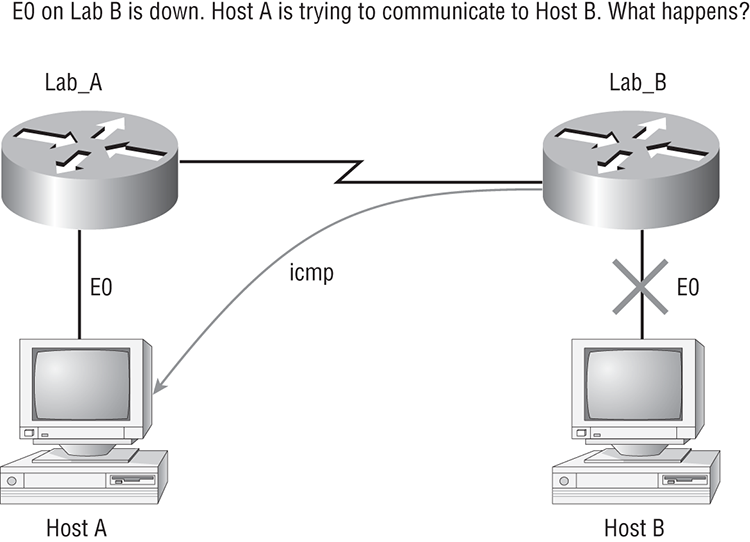
But before we get into the ARP protocol, let’s take another look at ICMP in action. Figure 4-10 shows an internetwork (it has a router, so it’s an internetwork, right?).
Figure 4-10: ICMP in action

Server1 (10.1.2.24) telnets to 10.1.1.5 from a DOS prompt. What do you think Server1 will receive as a response? Since Server1 will send the Telnet data to the default gateway, which is the router, the router will drop the packet because there isn’t a network 10.1.1.0 in the routing table. Because of this, Server1 will receive a destination unreachable back from ICMP.
Address Resolution Protocol (ARP)
Address Resolution Protocol (ARP) finds the hardware address of a host from a known IP address. Here’s how it works: when IP has a datagram to send, it must inform a Network Access protocol, such as Ethernet or wireless, of the destination’s hardware address on the local network. (It has already been informed by upper-layer protocols of the destination’s IP address.) If IP doesn’t find the destination host’s hardware address in the ARP cache, it uses ARP to find this information.
As IP’s detective, ARP interrogates the local network by sending out a broadcast asking the machine with the specified IP address to reply with its hardware address. So basically, ARP translates the software (IP) address into a hardware address—for example, the destination machine’s Ethernet board address—and from it, deduces its whereabouts on the LAN by broadcasting for this address. Figure 4-11 shows how an ARP looks to a local network.
Figure 4-11: Local ARP broadcast
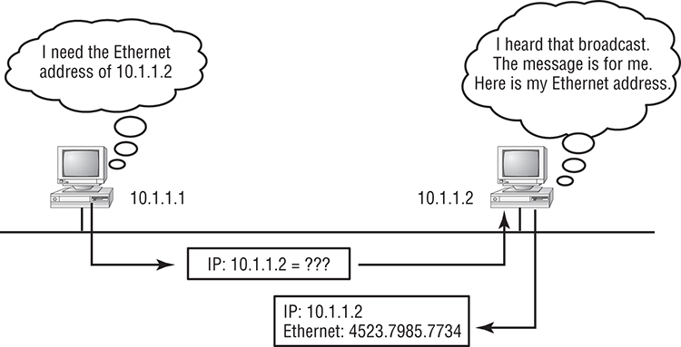
The following trace shows an ARP broadcast—notice that the destination hardware address is unknown and is all Fs in hex (all 1s in binary)—and is a hardware address broadcast:
 Flags:         0x00
 Status:        0x00
 Packet Length: 64
 Timestamp:     09:17:29.574000 12/06/03
Ethernet Header
 Destination:   FF:FF:FF:FF:FF:FF Ethernet Broadcast
 Source:        00:A0:24:48:60:A5
 Protocol Type: 0x0806 IP ARP
ARP - Address Resolution Protocol
 Hardware:                1 Ethernet (10Mb)
 Protocol:                0x0800 IP
 Hardware Address Length: 6
 Protocol Address Length: 4
 Operation:               1 ARP Request
 Sender Hardware Address: 00:A0:24:48:60:A5
 Sender Internet Address: 172.16.10.3
 Target Hardware Address: 00:00:00:00:00:00 (ignored)
 Target Internet Address: 172.16.10.10
Extra bytes (Padding):
 ................ 0A 0A 0A 0A 0A 0A 0A 0A 0A 0A 0A 0A 0A
  0A 0A 0A 0A 0A
Frame Check Sequence: 0x00000000
Reverse Address Resolution Protocol (RARP)
When an IP machine happens to be a diskless machine, it has no way of initially knowing its IP address. But it does know its MAC address. Reverse Address Resolution Protocol (RARP), as shown in Figure 4-12, discovers the identity of the IP address for diskless machines by sending out a packet that includes its MAC address and a request for the IP address assigned to that MAC address. A designated machine, called a RARP server, responds with the answer and the identity crisis is over. RARP uses the information it does know about the machine’s MAC address to learn its IP address and complete the machine’s ID portrait.
Proxy Address Resolution Protocol (Proxy ARP)
On a network, your hosts can’t have more than one default gateway configured. Think about this…What if the default gateway (router) happens to go down? The host won’t just start sending to another router automatically—you’ve got to reconfigure that host. But Proxy ARP can actually help machines on a subnet reach remote subnets without configuring routing or even a default gateway.
Figure 4-12: RARP broadcast example

One advantage of using Proxy ARP is that it can be added to a single router on a network without disturbing the routing tables of all the other routers that live there too. But there’s a serious downside to using Proxy ARP. Using Proxy ARP will definitely increase the amount of traffic on your network segment, and hosts will have a larger ARP table than usual in order to handle all the IP-to-MAC-address mappings. And Proxy ARP is configured on all Cisco routers by default—you should disable it if you don’t think you’re going to use it.
One last thought on Proxy ARP: Proxy ARP isn’t really a separate protocol. It is a service run by routers on behalf of other devices (usually PCs) that are separated from their query to another device by a router, although they think they share the subnet with the remote device. This lets the router provide its own MAC address in response to ARP queries attempting to resolve a distant IP address to a functional MAC address.
Summary
If you made it this far and understood everything the first time through, you should be proud of yourself. We really covered a lot of ground in this chapter, but understand that the information in this chapter is key to being able to navigate through the rest of this book.
And even if you didn’t get a complete understanding the first time around, don’t stress. It really wouldn’t hurt you to read this chapter more than once. There is still a lot of ground to cover, so make sure you’ve got it all down, and get ready for more. What we’re doing is building a foundation, and you want a strong foundation, right?
After you learned about the DoD model, the layers, and associated protocols, you learned about the oh-so-important IP addressing. I discussed in detail the difference between each class of address and how to find a network address, broadcast address, and valid host range, which is critical information to understand before going on to Chapter 5.
Since you’ve already come this far, there’s no reason to stop now and waste all those brainwaves and new neurons. So don’t stop—go through the written lab and review questions at the end of this chapter and make sure you understand each answer’s explanation. The best is yet to come!
Exam Essentials
Written Lab 4
In this section, you’ll complete the following lab to make sure you’ve got the information and concepts contained within it fully dialed in:
You can find the answers in Appendix A.
Written Lab 4: Internet Protocol (IP) Stack
Answer the following questions about TCP/IP:
1. Which transport protocol requires a three-way handshake to establish a new connection?
2. What layer of the DoD model is equivalent to the Transport layer of the OSI model?
3. Which protocol at the Transport layer is connectionless?
4. Which protocol at the Transport layer is connection-oriented?
5. What protocol at the Network layer provides management and messaging services for IP?
6. What is used to identify the protocol or service that is to be used in the transmission of frames?
7. The term for data at the Transport layer is what?
8. What is used to identify the protocol or service that is to be used in the transmission of segments?
9. What is used to identify the protocol or service that is to be used in the transmission of packets?
10. Which two layers of the OSI model are combined in the Internet Protocol suite Network Access layer?
Review Questions
You can find the answers in Appendix B.
1. What must happen if a DHCP IP conflict occurs?
A. Proxy ARP will fix the issue.
B. The client uses a gratuitous ARP to fix the issue.
C. The administrator must fix the conflict by hand at the DHCP server.
D. DHCE ignores the conflict.
2. Which options describe services that are provided by UDP? (Choose two.)
A. Session multiplexing
B. Connection-oriented
C. Segmentation
D. Reliable packet delivery
E. Best effort packet delivery
3. You want to implement a mechanism that automates the IP configuration, including IP address, subnet mask, default gateway, and DNS information. Which protocol will you use to accomplish this?
A. SMTP
B. SNMP
C. DHCP
D. ARP
4. What protocol is used to find the hardware address of a local device?
A. RARP
B. ARP
C. IP
D. ICMP
E. BootP
5. Which of the following are layers in the TCP/IP model? (Choose three.)
A. Application
B. Session
C. Transport
D. Internet
E. Data Link
F. Physical
6. Which layers of the OSI model are combined in the Internet Protocol suite Network Access layer? (Choose two.)
A. 1
B. 2
C. 3
D. 4
7. Which of the following describe the DHCP Discover message? (Choose two.)
A. It uses FF:FF:FF:FF:FF:FF as a layer 2 broadcast.
B. It uses UDP as the Transport layer protocol.
C. It uses TCP as the Transport layer protocol.
D. It does not use a layer 2 destination address.
8. Which layer 4 protocol is used for a Telnet connection?
A. IP
B. TCP
C. TCP/IP
D. UDP
E. ICMP
9. What protocol does a DHCP client use to verify that there is not a duplicate address assignment?
A. Acknowledge receipt of a TCP segment.
B. Ping to its own address to see if a response is detected.
C. Broadcast a Proxy ARP.
D. Broadcast a gratuitous ARP.
E. Telnet to its own IP address.
10. Which of the following services use TCP? (Choose three.)
A. DHCP
B. SMTP
C. SNMP
D. FTP
E. HTTP
F. TFTP
11. Which of the following services use UDP? (Choose three.)
A. DHCP
B. SMTP
C. SNMP
D. FTP
E. HTTP
F. TFTP
12. Which of the following are TCP/IP protocols used at the Application layer of the OSI model? (Choose three.)
A. IP
B. TCP
C. Telnet
D. FTP
E. TFTP
13. The following illustration shows a data structure header. What protocol is this header from?

A. IP
B. ICMP
C. TCP
D. UDP
E. ARP
F. RARP
14. If you use either Telnet or FTP, which is the highest layer you are using to transmit data?
A. Application
B. Presentation
C. Session
D. Transport
15. The DoD model (also called the TCP/IP stack) has four layers. Which layer of the DoD model is equivalent to the Network layer of the OSI model?
A. Application
B. Host-to-Host
C. Internet
D. Network Access
16. Which layers of the OSI model are combined in the Internet Protocol suite Application layer? (Choose two.)
A. 3
B. 4
C. 5
D. 6
E. 7
17. What layer in the TCP/IP stack is equivalent to the Transport layer of the OSI model?
A. Application
B. Host-to-Host
C. Internet
D. Network Access
18. Which statements are true regarding ICMP packets? (Choose two.)
A. ICMP guarantees datagram delivery.
B. ICMP can provide hosts with information about network problems.
C. ICMP is encapsulated within IP datagrams.
D. ICMP is encapsulated within UDP datagrams.
19. Which layer of the OSI model is associated with Token Ring Media Access Control, FDDI and Ethernet?
A. 4
B. 3
C. 2
D. 1
20. Which of the following protocols uses both TCP and UDP?
A. FTP
B. SMTP
C. Telnet
D. DNS