
Chapter 16
Intrusion Prevention
CISCO CCNA SECURITY EXAM OBJECTIVES COVERED IN THIS CHAPTER:
 6.1 Describe IPS deployment considerations
- Network-based IPS vs. host-based IPS
- Modes of deployment (inline, promiscuous - SPAN, tap)
- Placement (positioning of the IPS within the network)
- False positives, false negatives, true positives, true negatives
- 6.2 Describe IPS technologies
- Rules/signatures
- Detection/signature engines
- Trigger actions/responses (drop, reset, block, alert, monitor/log, shun)
- Blacklist (static and dynamic)
 It is no longer acceptable to sit and wait for the next attack and react afterward. In today’s threat-filled landscape, security professionals must take a proactive approach to preventing intrusions. Intrusion prevention systems are designed to identify and prevent attacks in real time. In this chapter, you will explore the intrusion prevention capabilities of the ASA.
In this chapter, you will learn the following:
- Deployment options of an IPS
- Advantages and disadvantages of an HIPS and an NIPS
- Proper positioning of an IPS
- Management of false positives and negatives
- Threat identification methods
- Methods of implementing high availability
- Trigger actions
IPS Terminology
To begin this chapter, you’ll learn a number of terms and concepts that apply to the process of intrusion prevention. A clear understanding of these will help support the rest of the chapter.
Threat
A threat is an identified security weakness to which any specific environment may or may not be vulnerable. For example, a threat might exist in the form of a new attack on Oracle database servers, but if you use Microsoft SQL Server, it is a threat to which you are not vulnerable. Risk is present only when a threat and a vulnerability to the threat both exist.
Risk
Risk is created when a threat exists to which a system is vulnerable. Unless these two conditions are both present, no risk exists.
Vulnerability
A vulnerability is any susceptibility to an external threat that a device or system may possess. A threat becomes a vulnerability only when the threat target is present in your environment and is in the state required to take advantage of the vulnerability. For example, if a threat to a file server exists only if the file server is lacking a security patch and your file server has the patch installed, the threat is not a vulnerability. Examples of vulnerabilities include the following:
- Weak passwords
- Missing security patches
- Lack of input validation
Exploit
An exploit occurs when a threat and a vulnerability both exist and a threat actor takes advantage of the situation. The term exploit also refers to the specific tool or attack methodology used. Some examples include the following:
- Scripts
- Malware
- Password crackers
Zero-Day Threat
A zero-day threat is any threat not yet remediated by malware vendors or software vendors. This type of threat cannot be detected through attack signature-based methods and is usually discovered only by malware or IPS/IDS software that uses heuristics. This approach identifies attacks by identifying traffic that is consistent with an attack rather than using a signature.
Actions
Actions refer to the operations that an intrusion prevention system (IPS) can take when an attack is recognized. Some examples of these actions are as follows:
- Drops means the IPS quietly drops the packets involved.
- Reset sends a packet with the RST flag that ends any TCP connection.
- Shun accomplishes the same purpose as a reset for non-TCP connections.
- Block is when the IPS directs another device (a router or firewall) to block the traffic.
Network-Based IPS vs. Host-Based IPS
The most common way to classify an IPS is based on its information source: network based and host based. A host-based intrusion detection system (HIPS) is installed on the device (for the purposes of this discussion, a server), and the system focuses solely on identifying attacks on that device only. This is in contrast to a network-based system, which monitors all traffic that goes through it looking for signs of attack on any machine in the network.
Host-Based IPS
An HIPS can be configured to also focus on attacks that may be relevant to the role that the server is performing (for example, looking for DNS pollution attacks on DNS servers). But there are drawbacks to these systems.
- A high number of false positives can cause a lax attitude on the part of the security team.
- Constant updating of signatures is needed.
- There’s a lag time between the release of the attack and the release of the signature.
- An HIPS cannot address authentication issues.
- Encrypted packets cannot be analyzed.
- In some cases, IPS software is susceptible itself to attacks.
Despite these shortcomings, an HIPS can play an important role in a multilayer defense system.
Network-Based IPS
A network-based IPS (NIPS) monitors network traffic on a local network segment. This is in contrast to a host-based IPS (HIPS) that monitors a single machine.
One of the disadvantages of an NIPS (which is an advantage of an HIPS) is that it cannot monitor any internal activity that occurs within a system, such as an attack against a system that is carried out by logging on to the system’s local terminal.
Most IPSs are programmed to react in certain ways in specific situations. Event notification and alerts are crucial to IPSs. These notifications and alerts inform administrators and security professionals when and where attacks are detected.
Promiscuous Mode
To monitor traffic on the network segment, the network interface card (NIC) must be operating in promiscuous mode. Moreover, an NIPS is affected by a switched network because generally an NIPS monitors only a single network segment, and each switch port is a separate collision domain.
Detection Methods
These systems can use several methods of detecting intrusions. The two main methods are as follows:
Signature Based Analyzes traffic and compares patterns, called signatures, that reside within the IDS database. This means it requires constant updating of the signature database.
Anomaly Based Analyzes traffic and compares it to normal traffic to determine whether the traffic is a threat. This means any traffic out of the ordinary will set off an alert.
Evasion Techniques
While IPSs can do some amazing things, they are not infallible. Several techniques have been developed over the years by malicious individuals that allow them to get malicious code past the IPS. Some of the more common approaches are covered in this section.
Packet Fragmentation
Packet fragmentation is the process of breaking a packet that is larger than the maximum transmission unit (MTU) into smaller pieces called fragments that abide by the size limits of the MTU. Various networking technologies enforce different MTUs. For example, while the MTU in Ethernet is 1,500 bytes, in an FDDI network the MTU is 4,470 bytes.
Routers on the network enforce the MTU and perform fragmentation of packets as needed to meet the MTU. When the fragments arrive at the destination, they are reassembled. To communicate exactly how the reassembly should occur, several header fields are used in the IP header. Figure 16.1 shows the IP header.

FIGURE 16.1 IP header fragmentation flags
Three fields are of interest.
- Identification provides a number that identifies packets that belong to the same transmission that need to be reassembled.
- Flag is a field consisting of three bits. As shown in Figure 16.1 , the first bit position 0 is reserved and not used in the fragmentation process; the second position when checked means don’t fragment this packet, in which case if the packet is oversized, an ICMP message will be sent to the source indicating it cannot be sent without fragmentation. The third position when checked means this packet is part of a series of fragments and there are more to come. If this is the last fragment in a series of fragments, this bit will not be checked.
- Fragment Offset values indicates to the reassembling host where this fragment belongs. It does so by indicating how many bytes away from the beginning of the payload the fragment is.
The fragmentation process follows this sequence:
- A router makes the decision that a packet must be fragmented.
- The router splits the packet into fragments, each with an identical IP header apart from the flag bits and the offset values.
- The destination reassembles the fragments. It recognizes the first fragment because it has an offset value of 0. It then uses the offset values of each fragment to properly position the fragments. It recognizes the last fragment because the More Fragments bit is off.
This process is illustrated in Figure 16.2 , where an MTU of 3,300 bytes is enforced on a packet that is 11,980 bytes. As you can see, the first fragment is given an Offset of 0 and the More Fragments bit is on, indicating more fragments to the receiver. The second packet has an Offset value of 410 and has the More Fragments bit on. The third and final fragment has an Offset value of 820, and since it is the last fragment, the More Fragments bit is off.

FIGURE 16.2 Fragmentation process
So, how does the fragmentation attack work? The attacker fragments the packet containing the malicious code so that it becomes difficult for the IPS to recognize the code in such a fragmented fashion. This process is shown in Figure 16.3 , where a malicious CGI script that, as shown in the original IP packet at the top, would probably be recognized by the IPS is split into fragments that may not be recognized by the IPS. (It is not important to understand the script.) In this case, a tool called fragroute was used to split the packet into fragments.
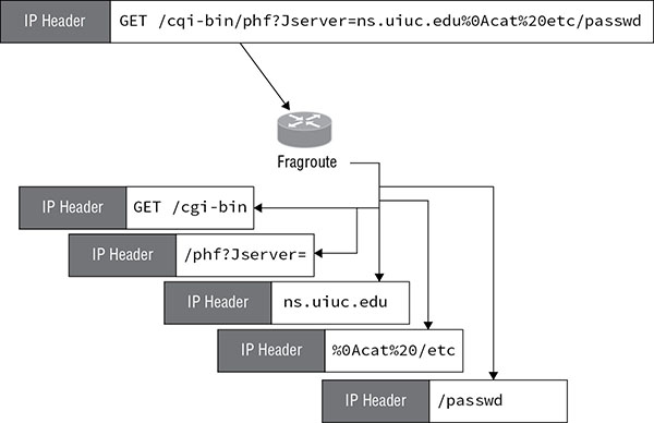
FIGURE 16.3 Fragmentation attack
The mitigations to this attack are to do the following:
- Use an IPS that performs signature analysis against the entire packet rather than individual fragments. This requires the ability to perform stream reassembly.
- Use protocol analysis to evaluate the entire packet for violation of protocol standards.
Injection Attacks
In an injection attack, the attacker inserts data that will be accepted by the IPS but will be ignored by the target system. One approach takes advantage of the TTL feature of IP and fragmentation. The time-to-live (TTL) value is used in IP to prevent a packet from looping endlessly. When a packet’s TTL value goes to zero (decremented at each hop), it gets dropped by the router.
In the attack (as shown in Figure 16.4 ), the attacker injects a bogus string into the attack code and then breaks the attack into three fragments. Then he manipulates the TTL value of the fragment containing the bogus string in such a way that the fragment dies (and never gets delivered) before it reaches the destination. If the IPS does not consider the fragment offset values or TTL values, it will detect the bogus string rather than the actual payload. The result is that after inspection by the IPS, the bogus string does not get delivered. The attack payload does.

FIGURE 16.4 Injection attack
Mitigations to this attack are as follows:
- Use an IPS that performs stream reassembly, which allows the IPS to recognize the attack.
- Use an IPS that performs TTL value assessment, which allows the IPS to recognize the lower TTL for the fragment containing the bogus string.
Alternate String Expressions
In many protocols, information can be communicated or expressed in multiple ways. For example, HTTP can accept strings expressed in hexadecimal, Unicode, or standard text expressions. Attackers can use this to evade an IPS sensor. If the IPS cannot perform protocol normalization (which decodes the payload to discover its significance), this attack may succeed.
Mitigations to this attack are as follows:
- Protocol analysis
- Protocol normalization
Introducing Cisco FireSIGHT
Cisco FireSIGHT offers threat protection capabilities that go beyond most IPSs. It not only detects and takes action to prevent attacks, it enables a better understanding of the exposures your environment may possess and helps you to take corrective actions to eliminate them. This section surveys the capabilities of FireSIGHT and the role it can play at various stages of an attack.
Capabilities
There are four categories of functions of which FireSIGHT is capable.
- Detection: Attack detection technologies include the following:
- IPS: Monitors for malicious and suspicious activity.
- Discovery: Enables visibility into all hosts, services, and applications running on the network. This includes traffic discovery in which you can identify the ways in which resources are being utilized.
- Learning: Reports on the state of the environment and detects when changes occur in real time.
- Adapting: When changes are detected, FireSIGHT can adapt its configuration to mitigate new risks.
- Acting: Actions that are available include the following:
- Block, alert, or modify suspicious traffic
- Remediate through custom responses such as blocking a downstream router or scanning a device
- Automate response and reporting
FireSIGHT is managed using the FireSIGHT Management Center. This application can be hosted on a FireSIGHT Management Center appliance or hosted on a virtual appliance on a VMware server.
Protections
The operations and features of FireSIGHT are best described in terms of how they would be utilized during an attack. Therefore, you will look at these protections in this way.
Before an Attack
The best way to mitigate attacks is to address them before they occur. FireSIGHT provides the following preventative technologies for this:
- Blacklisting: Traffic to and from specific IP addresses can be blacklisted, which means that your traffic will be neither sent to nor received from the IP address. When you identify problematic IP addresses, this is an action you take. Moreover, the FireSIGHT Management Center can dynamically download at configurable intervals a collection of IP addresses that have been identified by a threat intelligence team called Talos (https://www.talosintelligence.com/) as having a bad reputation in this regard. You can choose to add these to this list if desired.
- Advanced Malware Protection (AMP): Two AMP products are included. Cisco AMP for Endpoints is composed of connectors installed on endpoints. It uses a cloud-based detection process that offloads the detection burden to the cloud. Cisco AMP for Networks uses FirePOWER (covered in detail later in this chapter) appliances to detect malware in transit. It also can utilize the cloud for the latest malware. The system can also store detected files for submission to the Cisco Collective Security Intelligence Cloud for dynamic analysis.
During an Attack
While FireSIGHT uses the aforementioned methods to prevent attacks, prevention is not always possible. Once an attack is underway, the FireSIGHT IPS primarily takes actions by identifying and blocking malicious traffic. The IPS is a policy-based feature that allows for monitoring and blocking or altering malicious traffic when the IPS is deployed inline (deployment options are covered in the next section of this chapter).
FireSIGHT uses Snort technology (an IDS). This technology makes use of preprocessors, which examine traffic and in some cases modify the traffic in such a way that attacks that cannot be recognized by the signature can be recognized. For example, one preprocessor helps to recognize malicious code hidden by an IP fragmentation attack.
An IPS policy consists of the following:
- Rules that inspect the header content, packet size, and payload
- Rule state configuration based on FireSIGHT recommendations
- Preprocessors and other detection features
FireSIGHT also generates intrusion event information in a log that includes details such as the following:
- Date and time
- Event priority
- Brief description
- Name of the device
- Source IP address and port for the event
- Destination IP address and port for the event
- Name of the logged-in user
- Impact flag
After an Attack
After the attack, FireSIGHT provides an assessment of the attack, contains the attack, and helps bring the network back into a normal state. To do this, it uses several features:
- FireSIGHT discovery and awareness: This collects information about hosts, operating systems, applications, users, files, networks, geolocation information, and vulnerabilities that is used to report indicators of compromise.
- Dynamic file analysis: Captured files can be submitted to the Cisco Collective Security Intelligence Cloud for analysis. The cloud runs a test and returns a threat score to the FireSIGHT Management Center.
- Connection data and summaries: Connection data is information about detected sessions, including timestamps, IP addresses, geolocation, and applications.
Understanding Modes of Deployment
The FireSIGHT Management Center can also manage other monitoring devices such as appliances, virtual appliances, and ASA firewalls running software release ASA 9.2 and later. It is also commonly deployed in branch offices in the form of the FireSIGHT module in the ASA.
The devices managed by the FireSIGHT Management Center acting in the same role as legacy IPS sensors can be deployed in two modes.
Passive
The sensor receives a copy of the network traffic to analyze while the original traffic flows through the network. Because the sensor only receives a copy, and because by the time the copy is analyzed, the original traffic is long gone, FireSIGHT can only function as an intrusion detection system (IDS) when deployed in this mode. There are two ways to implement passive mode.
SPAN
Figure 16.5 illustrates this mode. The sensor is connected to a port on the switch to which all traffic has been mirrored by making the port a SPAN port. Notice that the traffic flow from the device inside the network to a device on the Internet (black dashed line) and then back (gray dashed line) is not interrupted.
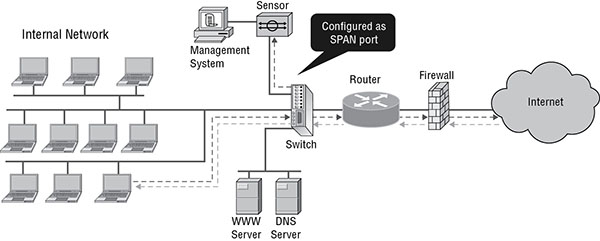
FIGURE 16.5 SPAN
Tap
In this deployment mode, the sensor is implemented as a network tap, as shown in Figure 16.6 . The tap is placed between the router and the layer 3 switch. It provides full-duplex connectivity between the devices and splits off two simplex mirrors of the full-duplex traffic. All traffic between the two devices must traverse the sensor.
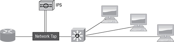
FIGURE 16.6 Tap
Inline
In this mode, the sensing device is placed in the line of traffic and analyzes the original traffic, not a copy in real time. Therefore, it can take actions on the traffic that allow it to operate as a true IPS. Figure 16.7 shows this mode’s operation.
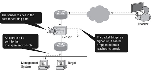
FIGURE 16.7 Inline mode
Positioning of the IPS within the Network
When making this key decision, consider the following factors:
- The features you are utilizing (attack detection, policy enforcement, surveillance, anomaly detection, etc.)
- Location of critical assets
- Bandwidth utilization
- Topology
Outside
One of the options is to place the sensor outside the perimeter firewall (ASA). When placed here, the sensor will generate a very high number of alarms because this is an exposure to the most untrusted network, the Internet. It will also generate many alarms that you will assess to be false positives (more on false positives in the final section of this chapter) because it will be composed of traffic that the ASA would have never allowed into the network. Figure 16.8 shows this option.
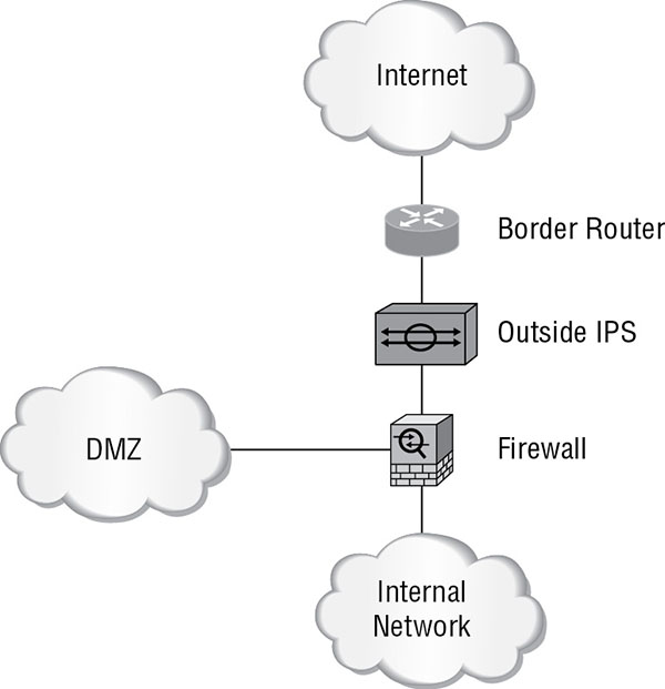
FIGURE 16.8 Outside deployment
DMZ
Servers in the DMZ are exposed to the Internet by design. While placing a sensor here will help to identify attacks on these exposed devices, keep in mind that if these servers are being deployed according to best practices, they will contain no sensitive information and will have been significantly hardened. Figure 16.9 shows this option.
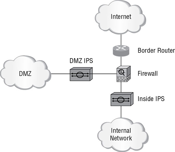
FIGURE 16.9 DMZ deployment
Inside
This is a positioning that yields the most benefit. While the perimeter ASA can provide protection, keep in mind that the users of these interior devices have varying levels of security expertise. This is also where all critical data will be located. Therefore, this will be the best place to deploy a single sensor. Figure 16.10 shows this option. In this option, FireSIGHT is deployed as a module in the ASA and is examining traffic destined for the internal network.
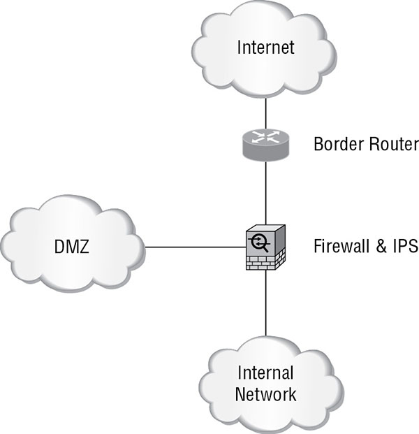
FIGURE 16.10 Inside deployment
Understanding False Positives, False Negatives, True Positives, and True Negatives
All IPSs and IDSs, including FireSIGHT, make incorrect assessments. In some cases, they fail to identify attacks or malicious traffic. In other cases, they alert you that an attack is under way when that is not the case. They also make correct assessments, alerting you to a real attack or ignoring traffic that is not an attack. There are terms used to describe all four of these scenarios. Table 16.1 identifies these terms. Keep in mind that true means the IPS was correct in its assessment and false means it was incorrect in its assessment.
TABLE 16.1 Assessment terms
| Term | Meaning |
| True positive | The IPS alerted you to an attack that is real. |
| True negative | The IPS did not alert you to a nonexistent attack. |
| False positive | The IPS alerted you to an attack that is nonexistent. |
| False negative | The IPS did not alert you to a real attack. |
Summary
In this chapter, you learned about some general IPS concepts, such as network-based and host-based deployments; modes of deployment such as inline, SPAN, and tap; and the positioning options available. You also were introduced to false positives and false negatives and the interpretation of these. The chapter covered how both rules and signatures are used in the process of identifying potential attacks. Finally assessment terms (false positive, false negative, etc.) were discussed.
Exam Essentials
Define IPS terminology. These terms include threat, risk, vulnerability, exploit, and zero-day threat.
Describe the actions of which an IPS is capable. Some examples of these actions are drops, which means the IPS quietly drops the packets involved; reset, which sends a packet with the RST flag, which ends any TCP connection; shun, which accomplishes the same purpose as a reset for non-TCP connections; and block, where the IPS directs another device (a router or firewall) to block the traffic.
Differentiate network-based and host-based IPS. A host-based intrusion prevention system (HIPS) is installed on the device (for the purposes of this discussion, a server), and the system focuses solely on identifying attacks on that device only. This is in contrast to a network-based system, which monitors all traffic that goes through it looking for signs of attack on any machine in the network.
Identify evasion techniques employed to defeat an IPS. These include packet fragmentation, injection attacks, and alternate string expressions.
List four categories of functions of which FireSIGHT is capable. These functions include detection, learning, adapting, and acting.
Describe the deployment modes of an IPS. These include passive modes, such as SPAN and tap, where the device can only operate an IDS. It also includes inline mode, in which the device can take actions on traffic as a true IPS.
Review Questions
-
Which of the following is an identified security weakness to which any specific environment may or may not be vulnerable?
- Threat
- Risk
- Vulnerability
- Exploit
-
Using which action does the IPS quietly drop the packets involved?
- Drop
- Reset
- Shun
- Block
-
Which of the following is not a drawback of a host-based IPS?
- A high number of false positives can cause a lax attitude on the part of the security team.
- Encrypted packets cannot be analyzed.
- It cannot monitor any internal activity that occurs within a system.
- It cannot address authentication issues.
-
Which evasion technique divides the packet into smaller pieces containing the malicious code so that it becomes difficult for the IPS to recognize the code?
- Packet fragmentation
- Injection attacks
- Injection attacks
- Cross-site scripting
-
Which of the following is not one of the four categories of functions of which FireSIGHT is capable?
- Detection
- Learning
- Adapting
- Block
-
Which of the following is any threat not yet remediated by malware vendors or software vendors?
- Zero-day attack
- Risk
- Vulnerability
- Exploit
-
Which capability of FireSIGHT is aimed at malware?
- Blacklisting
- AMP
- SNORT technology
- Discovery and awareness
-
Which deployment mode has the sensor connected to a port on the switch to which all traffic has been mirrored?
- SPAN
- Tap
- Inline
- Promiscuous
-
Which evasion technique relies on the fact that many protocols’ information can be communicated or expressed in multiple ways?
- Packet fragmentation
- Buffer overflows
- Injection attacks
- Cross-site scripting
-
Which of the following is susceptible to an external threat that a device or system may possess?
- Zero-day attack
- Risk
- Vulnerability
- Exploit
-
Using which action does the IPS accomplish the same purpose as a reset for non-TCP connections?
- Drop
- Reset
- Shun
- Block
-
In which deployment mode is the sensor placed in the line of traffic to analyze the original traffic, not a copy in real time?
- SPAN
- Tap
- Inline
- Promiscuous
-
In which positioning option will the IPS sensor generate a very high number of alarms?
- Outside
- DMZ
- Inside
- Remote
-
Which of the following occurs when a threat and a vulnerability both exist and a threat actor takes advantage of the situation?
- Zero-day attack
- Risk
- Vulnerability
- Exploit
-
Using which action does the IPS direct another device (a router or firewall) to block the traffic?
- Drop
- Reset
- Shun
- Block
-
In which deployment mode is the sensor placed between two layer 3 devices providing full-duplex connectivity between the devices and splitting off two simplex mirrors of the full-duplex traffic?
- SPAN
- Tap
- Inline
- Promiscuous
-
Which evasion technique inserts data that will be accepted by the IPS but will be ignored by the target system?
- Packet fragmentation
- Buffer overflow
- Injection attacks
- Cross-site scripting
-
Which of the following is a drawback of network-based IPS?
- A high number of false positives can cause a lax attitude on the part of the security team.
- Encrypted packets cannot be analyzed.
- It cannot monitor any internal activity that occurs within a system.
- It cannot address authentication issues.
-
Using which action does the IPS end any TCP connection?
- Drop
- Reset
- Shun
- Block
-
Which of the following is created when a threat exists to which a system is vulnerable?
- Zero-day attack
- Risk
- Mitigation
- Exploit