
Chapter 2
Spanning Tree Protocol
This chapter provides information and commands concerning the following topics:
Spanning Tree Protocol Definition
The spanning-tree standards offer the same safety that routing protocols provide in Layer 3 forwarding environments to Layer 2 bridging environments. A single best path to a main bridge is found and maintained in the Layer 2 domain, and other redundant paths are managed by selective port blocking. Appropriate blocked ports begin forwarding when primary paths to the main bridge are no longer available.
There are several different spanning-tree modes and protocols:
Per VLAN Spanning Tree (PVST+): This spanning-tree mode is based on the IEEE 802.1D standard and Cisco proprietary extensions. The PVST+ runs on each VLAN on the device up to the maximum supported, ensuring that each has a loop-free path through the network. PVST+ provides Layer 2 load balancing for the VLAN on which it runs. You can create different logical topologies by using the VLANs on your network to ensure that all of your links are used but that no one link is oversubscribed. Each instance of PVST+ on a VLAN has a single root device. This root device propagates the spanning-tree information associated with that VLAN to all other devices in the network. Because each device has the same information about the network, this process ensures that the network topology is maintained.
Rapid PVST+: This spanning-tree mode is the same as PVST+ except that it uses a rapid convergence based on the IEEE 802.1w standard. Beginning from Cisco IOS Release 15.2(4)E, the STP default mode is Rapid PVST+. To provide rapid convergence, Rapid PVST+ immediately deletes dynamically learned MAC address entries on a per-port basis upon receiving a topology change. By contrast, PVST+ uses a short aging time for dynamically learned MAC address entries. Rapid PVST+ uses the same configuration as PVST+ and the device needs only minimal extra configuration. The benefit of Rapid PVST+ is that you can migrate a large PVST+ install base to Rapid PVST+ without having to learn the complexities of the Multiple Spanning Tree Protocol (MSTP) configuration and without having to reprovision your network. In Rapid PVST+ mode, each VLAN runs its own spanning-tree instance up to the maximum supported.
Multiple Spanning Tree Protocol (MSTP): This spanning-tree mode is based on the IEEE 802.1s standard. You can map multiple VLANs to the same spanning-tree instance, which reduces the number of spanning-tree instances required to support a large number of VLANs. MSTP runs on top of the Rapid Spanning Tree Protocol (RSTP) (based on IEEE 802.1w), which provides for rapid convergence of the spanning tree by eliminating the forward delay and by quickly transitioning root ports and designated ports to the forwarding state. In a device stack, the cross-stack rapid transition (CSRT) feature performs the same function as RSTP. You cannot run MSTP without RSTP or CSRT.
Note
Default spanning-tree implementation for Catalyst 2950, 2960, 3550, 3560, and 3750 switches is PVST+. This is a per-VLAN implementation of 802.1D. Beginning from Cisco IOS Release 15.2(4)E, the STP default mode is Rapid PVST+ on all switch platforms.
Enabling Spanning Tree Protocol
|
Enables STP on VLAN 5 |
|
Disables STP on VLAN 5 |
Note
Many access switches such as the Catalyst 2960, 3550, 3560, 3650, 9200, and 9300 support a maximum 128 spanning trees using any combination of PVST+ or Rapid PVST+. The 2950 model supports only 64 instances. Any VLANs created in excess of 128 spanning trees cannot have a spanning-tree instance running in them. There is a possibility of an L2 loop that could not be broken in the case where a VLAN without spanning tree is transported across a trunk. It is recommended that you use MSTP if the number of VLANs in a common topology is high.
Caution
Spanning tree is enabled by default on VLAN 1 and on all newly created VLANs up to the spanning-tree limit. Disable spanning tree only if you are sure there are no loops in the network topology. When spanning tree is disabled and loops are present in the topology, excessive traffic and indefinite packet duplication can drastically reduce network performance. Networks have been known to crash in seconds due to broadcast storms created by loops.
Changing the Spanning-Tree Mode
You can configure different types of spanning trees on a Cisco switch. The options vary according to the platform.
|
Enables PVST+. This is the default setting |
|
Enters MST mode |
|
Enters MST subconfiguration mode Note Use the command no spanning-tree mst configuration to clear the MST configuration |
|
Enables Rapid PVST+ |
|
If any port on the device is connected to a port on a legacy IEEE 802.1D device, this command restarts the protocol migration process on the entire device This step is optional if the designated device detects that this device is running Rapid PVST+ |
Configuring the Root Switch
|
Modifies the switch priority from the default 32768 to a lower value to allow the switch to become the primary root switch for VLAN 5 Note This switch sets its priority to 24576. If any other switch has a priority set to below 24576 already, this switch sets its own priority to 4096 less than the lowest switch priority. If by doing this the switch has a priority of less than 1, this command fails |
|
Configures the switch to become the root switch for VLAN 5 Note The maximum switch topology width and the hello-time can be set within this command Tip The root switch should be a backbone or distribution switch |
|
Configures the switch to be the root switch for VLAN 5 and sets the network diameter to 6 Tip The diameter keyword defines the maximum number of switches between any two end stations. The range is from 2 to 7 switches. The default value is 7 Tip The hello-time keyword sets the hello-interval timer to any amount between 1 and 10 seconds. The default time is 2 seconds |
Configuring a Secondary Root Switch
|
Configures the switch to become the root switch for VLAN 5 should the primary root switch fail Note This switch lowers its priority to 28672. If the root switch fails and all other switches are set to the default priority of 32768, this becomes the new root switch |
|
Configures the switch to be the secondary root switch for VLAN 5 and sets the network diameter to 7 |
Configuring Port Priority
|
Moves to interface configuration mode |
|
Configures the port priority for the interface that is an access port |
|
Configures the VLAN port priority for an interface that is a trunk port Note If a loop occurs, spanning tree uses the port priority when selecting an interface to put into the forwarding state. Assign a higher priority value (lower numerical number) to interfaces you want selected first and a lower priority value (higher numerical number) to interfaces you want selected last The number can be between 0 and 240 in increments of 16. The default port priority is 128 |
Note
The port priority setting supersedes the physical port number in spanning-tree calculations.
Configuring the Path Cost
|
Moves to interface configuration mode |
|
Configures the cost for the interface that is an access port. The range is 1 to 200000000; the default value is derived from the media speed of the interface |
|
Configures the VLAN cost for an interface that is a trunk port. The VLAN number can be specified as a single VLAN ID number, a range of VLANs separated by a hyphen, or a series of VLANs separated by a comma. The range is 1 to 4094. For the cost, the range is 1 to 200000000; the default value is derived from the media speed of the interface Note If a loop occurs, STP uses the path cost when trying to determine which interface to place into the forwarding state. A higher path cost means a lower-speed transmission |
Configuring the Switch Priority of a VLAN
|
Configures the switch priority of VLAN 5 to 12288 |
Note
With the priority keyword, the range is 0 to 61440 in increments of 4096. The default is 32768. The lower the priority, the more likely the switch will be chosen as the root switch. Only the following numbers can be used as priority values:
0 |
4096 |
8192 |
12288 |
16384 |
20480 |
24576 |
28672 |
32768 |
36864 |
40960 |
45056 |
49152 |
53248 |
57344 |
61440 |
Caution
Cisco recommends caution when using this command. Cisco further recommends that the spanning-tree vlan x root primary or the spanning-tree vlan x root secondary command be used instead to modify the switch priority.
Configuring STP Timers
|
Changes the hello-delay timer to 4 seconds on VLAN 5 |
|
Changes the forward-delay timer to 20 seconds on VLAN 5 |
|
Changes the maximum-aging timer to 25 seconds on VLAN 5 |
Note
For the hello-time command, the range is 1 to 10 seconds. The default is 2 seconds.
For the forward-time command, the range is 4 to 30 seconds. The default is 15 seconds.
For the max-age command, the range is 6 to 40 seconds. The default is 20 seconds.
Configuring Optional Spanning-Tree Features
Although the following commands are not mandatory for STP to work, you might find these helpful to fine-tune your network.
PortFast
Note
By default, PortFast is disabled on all interfaces.
|
Moves to interface configuration mode |
|
Enables PortFast if the port is already configured as an access port |
|
Disables PortFast for the interface |
|
Enables the PortFast edge feature for the interface |
|
Enables PortFast network for the interface Note Use this command on trunk ports to enable the Bridge Assurance feature, which protects against loops by detecting unidirectional links in the spanning-tree topology Note Bridge Assurance is enabled globally by default |
|
Enables PortFast on a trunk port Caution Use the PortFast command only when connecting a single end station to an access or trunk port. Using this command on a port connected to a switch or hub might prevent spanning tree from detecting loops Note If you enable the voice VLAN feature, PortFast is enabled automatically. If you disable voice VLAN, PortFast is still enabled |
|
Globally enables PortFast on all switchports that are nontrunking Note You can override the spanning-tree portfast default global configuration command by using the spanning-tree portfast disable interface configuration command |
|
Displays PortFast information on interface GigabitEthernet 1/0/10 |
BPDU Guard (2xxx/older 3xxx Series)
|
Globally enables BPDU Guard on ports where portfast is enabled |
|
Enters interface range configuration mode |
|
Enables PortFast on all interfaces in the range Note Best practice is to enable PortFast at the same time as BPDU Guard |
|
Enables BPDU Guard on the interface Note By default, BPDU Guard is disabled |
|
Disables BPDU Guard on the interface |
|
Allows port to reenable itself if the cause of the error is BPDU Guard by setting a recovery timer |
|
Sets recovery timer to 400 seconds. The default is 300 seconds. The range is from 30 to 86 400 seconds |
|
Verifies whether BPDU Guard is enabled or disabled |
|
Displays errdisable recovery timer information |
BPDU Guard (3650/9xxx Series)
You can enable the BPDU Guard feature if your switch is running PVST+, Rapid PVST+, or MSTP.
The BPDU Guard feature can be globally enabled on the switch or can be enabled per port.
When you enable BPDU Guard at the global level on PortFast-enabled ports, spanning tree shuts down ports that are in a PortFast-operational state if any BPDU is received on them. When you enable BPDU Guard at the interface level on any port without also enabling the PortFast feature, and the port receives a BPDU, it is put in the error-disabled state.
|
Enables BPDU Guard globally Note By default, BPDU Guard is disabled |
|
Enters into interface configuration mode |
|
Enables the PortFast edge feature |
|
Returns to privileged EXEC mode |
BPDU Filter
|
Globally enables BPDU filtering on PortFast-enabled port; prevents ports in PortFast from sending or receiving BPDUs |
|
Enters interface range configuration mode |
|
Enables PortFast on all interfaces in the range |
|
Enables PortFast on all interfaces in the range Note This is the command for the 3650/9300 series |
|
Enables BPDU Filter on all interfaces in the range configured with “PortFast” Note By default, BPDU filtering is disabled. Also, BPDU Guard has no effect on an interface if BPDU filtering is enabled Caution Enabling BPDU filtering on an interface, or globally, is the same as disabling STP, which can result in spanning-tree loops being created but not detected |
|
Displays global BPDU filtering configuration information |
|
Displays detailed spanning-tree interface status and configuration information of the specified interface |
UplinkFast
|
Enables UplinkFast. UplinkFast provides fast convergence after a direct link failure |
|
Enables UplinkFast and sets the update packet rate to 200 packets/second Note UplinkFast cannot be set on an individual VLAN. The spanning-tree uplinkfast command affects all VLANs |
Note For the max-update-rate argument, the range is 0 to 32,000 packets/second. The default is 150. If you set the rate to 0, station-learning frames are not generated. This will cause STP to converge more slowly after a loss of connectivity |
|
|
Verifies whether UplinkFast has been enabled |
|
Displays spanning-tree UplinkFast status, which includes maximum update packet rate and participating interfaces |
Note
UplinkFast cannot be enabled on VLANs that have been configured for switch priority.
Note
UplinkFast is most useful in access layer switches, or switches at the edge of the network. It is not appropriate for backbone devices.
Note
You can configure the UplinkFast feature for Rapid PVST+ or for the MSTP, but the feature remains disabled (inactive) until you change the spanning-tree mode to PVST+.
BackboneFast
|
Enables BackboneFast. BackboneFast is initiated when a root port or blocked port receives an inferior BPDU from its designated bridge |
|
Verifies BackboneFast has been enabled |
|
Displays spanning-tree BackboneFast status, which includes the number of root link query protocol data units (PDUs) sent/received and number of BackboneFast transitions |
Note
You can configure the BackboneFast feature for Rapid PVST+ or for the MSTP, but the feature remains disabled (inactive) until you change the spanning-tree mode to PVST+.
Note
If you use BackboneFast, you must enable it on all switches in the network.
Root Guard
You can use Root Guard to limit which switch can become the root bridge. Root Guard should be enabled on all ports where the root bridge is not anticipated, such as access ports.
|
Moves to interface configuration mode |
|
Enables Root Guard on the interface |
|
Indicates whether any ports are in a root-inconsistent state |
|
Displays the status and configuration of the root bridge Note The show spanning-tree root command output includes root ID for all VLANs, the associated root costs, timer settings, and root ports |
|
Displays detailed spanning-tree state and configuration for each VLAN on the switch, including bridge and root IDs, timers, root costs, and forwarding status |
Note
You cannot enable both Root Guard and Loop Guard at the same time.
Note
Root Guard enabled on an interface applies to all VLANs to which the interface belongs.
Note
Do not enable Root Guard on interfaces to be used by the UplinkFast feature.
Loop Guard
Loop Guard is used to prevent alternate or root ports from becoming designated ports due to a failure that leads to a unidirectional link. Loop Guard operates only on interfaces that are considered point to point by the spanning tree. Spanning tree determines a port to be point to point or shared from the port duplex setting. You can use Loop Guard to prevent alternate or root ports from becoming designated ports because of a failure that leads to a unidirectional link. This feature is most effective when it is enabled on the entire switched network. When Loop Guard is enabled, spanning tree does not send BPDUs on root or alternate ports.
Note
Both the port duplex and the spanning-tree link type can be set manually.
Note
You cannot enable both Loop Guard and Root Guard on the same port. The Loop Guard feature is most effective when it is configured on the entire switched network.
|
Shows which ports are alternate or root ports |
|
Shows which ports are alternate or root ports when the switch is operating in MST mode |
|
Moves to global configuration mode |
|
Enables Loop Guard globally on the switch for those interfaces that the spanning tree identifies as point to point |
|
Moves to interface configuration mode |
|
Enables Loop Guard on all the VLANs associated with the selected interface |
|
Returns to privileged EXEC mode |
|
Verifies whether Loop Guard has been enabled |
|
Display spanning-tree link type. A link type of “point to point” is required for Loop Guard |
Unidirectional Link Detection
|
Enables unidirectional link detection (UDLD) on all fiber-optic interfaces to determine the Layer 1 status of the link Note By default, UDLD is disabled |
|
Enables UDLD aggressive mode on all fiber-optic interfaces |
|
Moves to interface configuration mode |
|
Enables UDLD on this interface (required for copper-based interfaces) in normal or aggressive mode Note On a fiber-optic (FO) interface, the interface command udld port overrides the global command udld enable. Therefore, if you issue the command no udld port on an FO interface, you will still have the globally enabled udld enable command to deal with |
|
Displays UDLD information |
|
Displays UDLD information for interface Gigabit Ethernet 1/0/1 |
|
Resets all interfaces shut down by UDLD Note You can also use the shutdown command, followed by a no shutdown command in interface configuration mode, to restart a disabled interface |
Configuring and Verifying Port Error Conditions
A port is “error-disabled” when the switch detects any one of a number of port violations. No traffic is sent or received when the port is in error-disabled state. The show errdisable detect command displays a list for the possible error-disabled reasons and whether enabled.
The errdisable detect cause command allows the network device administrator to enable or disable detection of individual error-disabled causes. All causes are enabled by default. All causes, except for per-VLAN error disabling, are configured to shut down the entire port.
The errdisable recovery command enables the network device administrator to configure automatic recovery mechanism variables. This would allow the switch port to again send and receive traffic after a configured period of time if the initial error condition is no longer present. All recovery mechanisms are disabled by default.
|
Enables error detection for all error-disabled causes |
|
Enables per-VLAN error-disable for BPDU Guard |
|
Enables error detection for DHCP snooping |
|
Enables error detection for Dynamic Trunk Protocol (DTP) flapping |
|
Enables error detection for invalid Gigabit Interface Converter (GBIC) module. Note You can also use the shutdown command, followed by a no shutdown command in interface configuration mode, to restart a disabled interface. This error refers to an invalid small form-factor pluggable (SFP) module on the switch |
|
Enables error detection for inline power |
|
Enables error detection for link-state flapping |
|
Enables error detection for detected loopbacks |
|
Enables error detection for the Port Aggregation Protocol (PAgP) flap error-disabled cause |
|
Enables voice-aware 802.1X security |
|
Enables error detection on an SFP configuration mismatch |
|
Configures errdisable recovery timer to 3600 seconds Note The same interval is applied to all causes. The range is 30 to 86,400 seconds. The default interval is 300 seconds |
|
Enables the error-disabled mechanism to recover from specific cause parameter. Parameters are shown below |
|
Enables the timer to recover from all error-disabled causes |
|
Enables the timer to recover from BPDU Guard error-disabled state |
|
Enable the timer to recover from the EtherChannel misconfiguration error-disabled state |
|
Enables the timer to recover from the DHCP snooping error-disabled state |
|
Enables the timer to recover from the DTP-flap error-disabled state |
|
Enables the timer to recover from the GBIC module error-disabled state Note This error refers to an invalid SFP error-disabled state |
|
Enables the timer to recover for inline power |
|
Enables the timer to recover from the link-flap error-disabled state |
|
Enables the timer to recover from a loopback error-disabled state |
|
Enables the timer to recover from the PAgP-flap error-disabled state |
|
Enables the timer to recover from a port security violation disabled state |
|
Enables the timer to recover from an IEEE 802.1X-violation disabled state |
|
Enables the timer to recover from an SFP configuration mismatch |
|
Displays error-disabled detection status |
|
Display begins with the line that matches the expression Note expression is the output to use as a reference point |
|
Display excludes lines that match the expression |
|
Display includes lines that match the expression |
|
Displays the error-disabled recovery timer status information |
|
Display begins with the line that matches the expression |
|
Display excludes lines that match the expression |
|
Display includes lines that match the expression |
Enabling Rapid Spanning Tree
|
Enables Rapid PVST+ |
|
Restarts the protocol migration process. With no arguments, the command is applied to every port of the switch |
|
Restarts the protocol migration process on interface GigabitEthernet 1/0/1 |
|
Restarts the protocol migration process on interface port-channel 1 |
|
Displays mode, root and bridge IDs, participating ports, and their spanning-tree states |
|
Summarizes configured port states, including spanning-tree mode |
|
Displays a detailed summary of spanning-tree interface information, including mode, priority, system ID, MAC address, timers, and role in the spanning tree for each VLAN and port |
Rapid Spanning Tree Link Types
The link type in RSTP can predetermine the active role that the port plays as it stands by for immediate transition to a forwarding state, if certain parameters are met. These parameters are different for edge ports and non-edge ports. An edge port is a switch port that is never intended to be connected to another switch device. It immediately transitions to the forwarding state when enabled—similar to an STP port with the PortFast featured enabled. However, an edge port that receives a BPDU immediately loses its edge port status and becomes a normal spanning-tree port. Non-edge ports are ports that are intended to be connected to another switch device. Link type is automatically determined but can be overwritten with an explicit port configuration. There are two different link types for non-edge ports, as shown in Table 2-1.
Link Type |
Description |
Point-to-point |
A port operating in full-duplex mode. It is assumed that the port is connected to a single switch device at the other end of the link |
Shared |
A port operating in half-duplex mode. It is assumed that the port is connected to shared media where multiple switches may exist |
TABLE 2-1 RSTP Non-Edge Link Types
spanning-tree mode rapid-pvst |
Enables Rapid PVST+ |
interface gigabitethernet 1/0/1 |
Moves to interface configuration mode |
spanning-tree link-type auto |
Sets the link type based on the duplex setting of the interface |
spanning-tree link-type point-to-point |
Specifies that the interface is a point-to-point link |
spanning-tree link-type shared |
Specifies that the interface is a shared medium |
exit |
Returns to global configuration mode |
Enabling Multiple Spanning Tree
|
Enters MST mode |
|
Enters MST configuration submode |
|
Maps VLAN 4 to Multiple Spanning Tree (MST) instance 1 |
|
Maps VLANs 1–15 to MST instance 1 |
|
Maps VLANs 10, 20, and 30 to MST instance 1 Note For the instance x vlan y command, the instance must be a number between 1 and 15, and the VLAN range is 1 to 4094 |
|
Specifies the name for the MST region. The default is an empty string Note The name argument can be up to 32 characters long and is case sensitive |
|
Specifies the revision number Note The range for the revision argument is 0 to 65,535 Note For two or more bridges to be in the same MST region, they must have the identical MST name, VLAN-to-instance mapping, and MST revision number |
|
Displays the summary of what is currently configured for the MST region |
|
Verifies the configuration by displaying a summary of what you have configured for the MST region |
|
Applies all changes and returns to global configuration mode |
|
Sets the bridge priority for the spanning tree to 4096. The priority can be a number from 0–61440 in increments of 4096 Caution Changing spanning-tree modes can disrupt traffic because all spanning-tree instances are stopped for the old mode and restarted in the new mode Note You cannot run both MSTP and PVST at the same time |
|
Configures a switch as a primary root switch within MST instance 1. The primary root switch priority is 24,576 |
|
Configures a switch as a secondary root switch within MST instance 1. The secondary root switch priority is 28,672 |
|
Configures an interface with a port priority of 0 for MST instance 20 Note The priority range is 0 to 240 in increments of 16, where the lower the number, the higher the priority. The default is 128. The range and increment values are platform and IOS version dependent |
|
Sets the path cost to 250 for MST instance 2 calculations. Path cost is 1 to 200,000,000, with higher values meaning higher costs |
|
Returns to privileged EXEC mode |
Verifying the Extended System ID
|
Verifies that the extended system ID is enabled |
|
Displays the extended system ID as part of the bridge ID Note The 12-bit extended system ID is the VLAN number for the instance of PVST+ and PVRST+ spanning tree. In MST, these 12 bits carry the instance number |
Verifying STP
|
Displays STP information |
|
Displays STP information on active interfaces only |
|
Displays status and configuration of this bridge |
|
Displays a detailed summary of interface information |
|
Displays STP information for interface gigabitethernet 1/0/1 |
|
Displays a summary of port states |
|
Displays the total lines of the STP section |
|
Displays STP information for VLAN 5 |
|
Displays the MST region configuration |
|
Displays the message digest 5 (MD5) authentication digest included in the current MST configuration identifier (MSTCI) |
|
Displays the MST information for instance 1 |
|
Displays the MST information for interface GigabitEthernet 1/0/1 |
|
Displays the MST information for instance 1 on interface GigabitEthernet 1/0/1 |
|
Shows detailed information about MST instance 1 |
Troubleshooting Spanning Tree Protocol
|
Displays all spanning-tree debugging events |
|
Displays spanning-tree debugging topology events |
|
Displays spanning-tree debugging BackboneFast events |
|
Displays spanning-tree debugging UplinkFast events |
|
Displays all MST debugging events |
|
Displays spanning-tree port state changes |
|
Displays PVST+ events |
Configuration Example: PVST+
Figure 2-1 shows the network topology for the configuration of PVST+ using commands covered in this chapter. Assume that other commands needed for connectivity have already been configured. For example, all inter-switch links in this topology are configured as 802.1Q trunks.
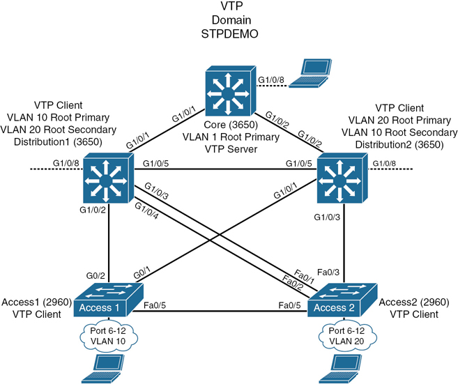
Figure 2-1 Network Topology for STP Configuration Example
Core Switch (3650)
|
Moves to privileged EXEC mode |
|
Moves to global configuration mode |
|
Sets the host name |
|
Turns off Domain Name System (DNS) queries so that spelling mistakes do not slow you down |
|
Changes the switch to VTP server mode. This is the default mode |
|
Configures the VTP domain name to STPDEMO |
|
Creates VLAN 10 and enters VLAN configuration mode |
|
Assigns a name to the VLAN |
|
Returns to global configuration mode |
|
Creates VLAN 20 and enters VLAN configuration mode |
|
Assigns a name to the VLAN |
|
Returns to global configuration mode |
|
Configures the switch to become the root switch for VLAN 1 |
|
Returns to privileged EXEC mode |
|
Saves the configuration to NVRAM |
Distribution 1 Switch (3650)
|
Moves to privileged EXEC mode |
|
Moves to global configuration mode |
|
Sets the host name |
|
Turns off DNS queries so that spelling mistakes do not slow you down |
|
Configures the VTP domain name to STPDEMO |
|
Changes the switch to VTP client mode |
|
Configures the switch to become the root switch of VLAN 10 |
|
Configures the switch to become the secondary root switch of VLAN 20 |
|
Returns to privileged EXEC mode |
|
Saves the configuration to NVRAM |
Distribution 2 Switch (3650)
|
Moves to privileged EXEC mode |
|
Moves to global configuration mode |
|
Sets the host name |
|
Turns off DNS queries so that spelling mistakes do not slow you down |
|
Configures the VTP domain name to STPDEMO |
|
Changes the switch to VTP client mode |
|
Configures the switch to become the root switch of VLAN 20 |
|
Configures the switch to become the secondary root switch of VLAN 10 |
|
Returns to privileged EXEC mode |
|
Saves the configuration to NVRAM |
Access 1 Switch (2960)
|
Moves to privileged EXEC mode |
|
Moves to global configuration mode |
|
Sets the host name |
|
Turns off DNS queries so that spelling mistakes do not slow you down |
|
Configures the VTP domain name to STPDEMO |
|
Changes the switch to VTP client mode |
|
Moves to interface range configuration mode |
|
Places all interfaces in switchport access mode |
|
Assigns all interfaces to VLAN 10 |
|
Places all ports directly into forwarding mode |
|
Enables BPDU Guard |
|
Moves back to privileged EXEC mode |
|
Saves the configuration to NVRAM |
Access 2 Switch (2960)
|
Moves to privileged EXEC mode |
|
Moves to global configuration mode |
|
Sets the host name |
|
Turns off DNS queries so that spelling mistakes do not slow you down |
|
Configures the VTP domain name to STPDEMO |
|
Changes the switch to VTP client mode |
|
Moves to interface range configuration mode |
|
Places all interfaces in switchport access mode |
|
Assigns all interfaces to VLAN 20 |
|
Places all ports directly into forwarding mode |
|
Enables BPDU Guard |
|
Moves back to global configuration mode |
|
Ensures this switch does not become the root switch for VLAN 10 |
|
Returns to privileged EXEC mode |
|
Saves config to NVRAM |
Spanning-Tree Migration Example: PVST+ to Rapid-PVST+
The topology in Figure 2-1 is used for this migration example and adds to the configuration of the previous example.
Rapid-PVST+ uses the same BPDU format as 802.1D. This interoperability between the two spanning-tree protocols enables a longer conversion time in large networks without disrupting services.
The spanning-tree features UplinkFast and BackboneFast in 802.1D-based PVST+ are already incorporated in the 802.1w-based Rapid-PVST+ and are disabled when you enable Rapid-PVST+. The 802.1D-based features of PVST+ such as PortFast, BPDU Guard, BPDU Filter, Root Guard, and Loop Guard are applicable in Rapid-PVST+ mode and need not be changed.
Access 1 Switch (2960)
|
Moves to privileged EXEC mode |
|
Moves to global configuration mode |
|
Enables 802.1w-based Rapid-PVST+ |
|
Removes UplinkFast programming line if it exists |
|
Removes BackboneFast programming line if it exists |
Access 2 Switch (2960)
|
Moves to privileged EXEC mode |
|
Moves to global configuration mode |
|
Enables 802.1w-based Rapid-PVST+ |
Distribution 1 Switch (3650)
|
Moves to privileged EXEC mode |
|
Moves to global configuration mode |
|
Enables 802.1w-based Rapid-PVST+ |
Distribution 2 Switch (3650)
|
Moves to privileged EXEC mode |
|
Moves to global configuration mode |
|
Enables 802.1w-based Rapid-PVST+ |
Core Switch (3650)
|
Moves to privileged EXEC mode |
|
Moves to global configuration mode |
|
Enables 802.1w-based Rapid-PVST+ |