
Chapter 13
Overlay Tunnels and VRF
This chapter provides information about the following topics:
Caution
Your hardware platform or software release might not support all the commands documented in this chapter. Please refer to Cisco.com for specific platform and software release notes.
Generic Routing Encapsulation (GRE)
GRE, defined in RFC 2784, is a carrier protocol that can be used with a variety of underlying transport protocols and that can carry a variety of passenger protocols. RFC 2784 also covers the use of GRE with IPv4 as the transport protocol and the passenger protocol. Cisco IOS Software supports GRE as the carrier protocol with many combinations of passenger and transport protocols such as:
GRE over IPv4 networks: GRE is the carrier protocol, and IPv4 is the transport protocol. This is the most common type of GRE tunnel.
GRE over IPv6 networks: GRE is the carrier protocol, and IPv6 is the transport protocol. Cisco IOS Software supports IPv4 and IPv6 as passenger protocols with GRE/IPv6.
Configuring an IPv4 GRE Tunnel
Perform the following configuration steps to configure a GRE tunnel. A tunnel interface is used to transport protocol traffic across a network that does not normally support the protocol. To build a tunnel, a tunnel interface must be defined on each of two routers and the tunnel interfaces must reference each other. At each router, the tunnel interface must be configured with a Layer 3 address. The tunnel endpoints, tunnel source, and tunnel destination must be defined, and the type of tunnel must be selected. Optional steps can be performed to customize the tunnel.
|
Moves to interface configuration mode |
|
Specifies the encapsulation protocol to be used in the tunnel. By default, the tunnel protocol is GRE and the transport protocol is IPv4; therefore entering this command is optional and won’t appear in the device’s running configuration |
|
Assigns an IP address and subnet mask to the tunnel interface |
Or
|
Identifies the local source of the tunnel. You can use either an interface name or the IP address of the interface that will transmit tunneled packets Note The tunnel source can be a physical interface or a loopback interface |
|
Identifies the remote destination IP address |
|
Defines the tunnel bandwidth for use with a routing protocol or QoS in kilobits per second. In the example, the bandwidth is set to 8192 Kbps |
|
Sets the tunnel keepalives to 3 seconds and the number of retries to five to ensure that bidirectional communication exists between tunnel endpoints. The default timer is 10 seconds, with three retries |
|
Set the maximum transmission unit (MTU) size of IP packets sent on an interface to 1400 bytes. The default MTU is 1500 bytes Note The GRE tunnel adds a minimum of 24 bytes to the packet size |
Configuring an IPv6 GRE Tunnel
The same process that is described for IPv4 is used to configure an IPv6 GRE tunnel.
|
Moves to interface configuration mode |
|
Specifies the encapsulation protocol to be used in the tunnel |
|
Assigns an IPv6 address and subnet mask to the tunnel interface |
Or
|
Identifies the local source of the tunnel. You can use either an interface name or the IPv6 address of the interface that will transmit tunneled packets Note The tunnel source can be a physical interface or a loopback interface |
|
Identifies the remote destination IPv6 address |
|
Defines the tunnel bandwidth for use with a routing protocol or QoS in kilobits per second. In the example, the bandwidth is set to 4096 Kbps |
|
Sets the tunnel keepalives to 3 seconds and the number of retries to five to ensure that bidirectional communication exists between tunnel endpoints. The default timer is 10 seconds, with three retries |
|
Set the maximum transmission unit (MTU) size of IPv6 packets sent on an interface to 1400 bytes. The default MTU is 1500 bytes Note The GRE tunnel adds a minimum of 24 bytes to the packet size |
Verifying IPv4 and IPv6 GRE Tunnels
|
Displays general information about the tunnel interface |
|
Displays IPv4 information about the tunnel interface |
|
Displays IPv6 information about the tunnel interface |
Configuration Example: IPv4 and IPv6 GRE Tunnels with OSPFv3
Figure 13-1 shows the network topology for the configuration that follows, which demonstrates how to configure IPv4 and IPv6 GRE tunnels to allow for OSPFv3 connectivity between two customer edge routers that peer with separate ISP routers. This example assumes that ISP1 and ISP2 are configured to route traffic across the underlay network between CE1 and CE2. Tunnel 0 is used for IPv4 and Tunnel 1 is used for IPv6.
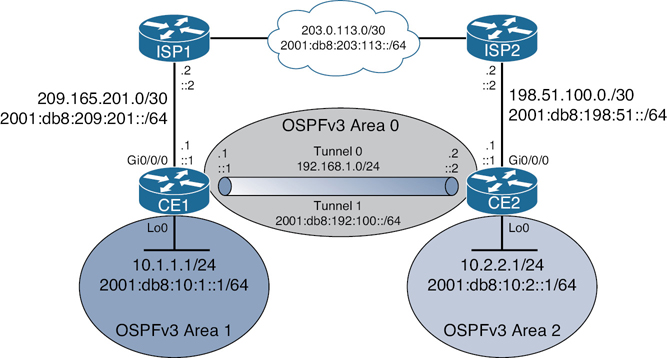
Figure 13-1 Network Topology for IPv4/IPv6 GRE Example
The example is built following these steps:
Step 1. Underlay configuration (physical/logical interfaces, default routing).
Step 2. Overlay configuration (tunnel interfaces).
Step 3. Overlay routing with OSPFv3.
Step 1: Underlay Configuration
|
Enables routing for IPv6 packets |
|
Enters interface configuration mode |
|
Applies an IPv4 address to the interface |
|
Applies an IPv6 address to the interface |
|
Enables the interface |
|
Exits interface configuration mode |
|
Enters interface configuration mode |
|
Applies an IPv4 address to the interface |
|
Applies an IPv6 address to the interface |
|
Exits interface configuration mode |
|
Defines an IPv4 default route to send all packets to ISP1 |
|
Defines an IPv6 default route to send all packets to ISP1 |
|
Enables routing for IPv6 packets |
|
Enters interface configuration mode |
|
Applies an IPv4 address to the interface |
|
Applies an IPv6 address to the interface |
|
Enables the interface |
|
Exits interface configuration mode |
|
Enters interface configuration mode |
|
Applies an IPv4 address to the interface |
|
Applies an IPv6 address to the interface |
|
Exits interface configuration mode |
|
Defines an IPv4 default route to send all packets to ISP1 |
|
Defines an IPv6 default route to send all packets to ISP1 |
Step 2: Overlay Configuration
|
Enters interface configuration mode |
|
Applies an IPv4 address to the interface |
|
Defines the physical source of the tunnel |
|
Defines the tunnel destination across the underlay network |
|
Enables GRE tunnel mode for IPv4. This is the default value and won’t appear in the running configuration |
|
Lowers the MTU to 1400 bytes from its default of 1500 |
|
Enables IPv6 on the interface. This is required for OSPFv3 routing in the next step since there is no IPv6 address on Tunnel 0 |
|
Enters interface configuration mode |
|
Applies an IPv6 address to the interface |
|
Defines the physical source of the tunnel |
|
Defines the tunnel destination across the underlay network |
|
Enables GRE tunnel mode for IPv6 |
|
Enters interface configuration mode |
|
Applies an IPv4 address to the interface |
|
Defines the physical source of the tunnel |
|
Defines the tunnel destination across the underlay network |
|
Enables GRE tunnel mode for IPv4. This is the default value and won’t appear in the running configuration |
|
Lowers the MTU to 1400 bytes from its default of 1500 |
|
Enables IPv6 on the interface. This is required for OSPFv3 routing in the next step since there is no IPv6 address on Tunnel 0 |
|
Enters interface configuration mode |
|
Applies an IPv6 address to the interface |
|
Defines the physical source of the tunnel |
|
Defines the tunnel destination across the underlay network |
|
Enables GRE tunnel mode for IPv6 |
Step 3: Overlay Routing with OSPFv3
|
Starts OSPFv3 with a process ID of 1 |
|
Creates the IPv4 unicast address family |
|
Defines a router ID of 1.1.1.1 |
|
Creates the IPv6 unicast address family |
|
Defines a router ID of 1.1.1.1 |
|
Enters interface configuration mode |
|
Assigns the Tunnel 0 interface to area 0 for the OSPFv3 IPv4 address family |
|
Enters interface configuration mode |
|
Assigns the Tunnel 1 interface to area 0 for the OSPFv3 IPv6 address family |
|
Enters interface configuration mode |
|
Assigns the Loopback 0 interface to area 1 for the OSPFv3 IPv4 address family |
|
Assigns the Loopback 0 interface to area 1 for the OSPFv3 IPv6 address family |
|
Starts OSPFv3 with a process ID of 1 |
|
Creates the IPv4 unicast address family |
|
Defines a router ID of 2.2.2.2 |
|
Creates the IPv6 unicast address family |
|
Defines a router ID of 2.2.2.2 |
|
Enters interface configuration mode |
|
Assigns the Tunnel 0 interface to area 0 for the OSPFv3 IPv4 address family |
|
Enters interface configuration mode |
|
Assigns the Tunnel 1 interface to area 0 for the OSPFv3 IPv6 address family |
|
Enters interface configuration mode |
|
Assigns the Loopback 0 interface to area 1 for the OSPFv3 IPv4 address family |
|
Assigns the Loopback 0 interface to area 1 for the OSPFv3 IPv6 address family |
Site-to-Site GRE over IPsec
In GRE over IPsec (usually written GRE/IPsec for short), data packets are first encapsulated within GRE/IP, which results in a new IP packet being created inside the router. This packet is then selected for encryption (the traffic selector being GRE from local to remote endpoint IP address), and encapsulated into IPsec. Since a new IP header has already been added, IPsec transport mode is generally used to keep the overhead to a minimum. There are two different ways to encrypt traffic over a GRE tunnel:
Using crypto maps (old method)
Using tunnel IPsec profiles (newer method)
Note
Even though crypto maps are no longer recommended for tunnels, they are still widely deployed and should be understood.
The two GRE configuration scenarios that follow build on the previous GRE example but focus only on IPv4. You would configure one of the two scenarios, not both. Refer to Figure 13-1 for addressing information.
GRE/IPsec Using Crypto Maps
After the GRE tunnel has been configured, follow these steps to enable IPsec using crypto maps:
Step 1. Define a crypto ACL.
Step 2. Configure an ISAKMP policy for IKE SA.
Step 3. Configure pre-shared keys (PSKs).
Step 4. Create a transform set.
Step 5. Build a crypto map.
Step 6. Apply the crypto map to the outside interface.
Step 1: Define a Crypto ACL
|
Defines the crypto ACL that identifies traffic entering the GRE tunnel. This traffic is encrypted by IPsec |
|
The crypto ACL on CE2 is a mirror image of the ACL on CE1 |
Step 2: Configure an ISAKMP Policy for IKE SA (repeat on CE2)
|
Creates an ISAKMP policy number 1. Numbers range from 1 to 1000 |
|
Enables the use of PSKs for authentication. Option to use RSA signatures instead |
|
Enables SHA-256 for hashing. Options are MD5, SHA, SHA-256, SHA-384, and SHA-512 |
|
Enables AES-256 for encryption. Options are DES, 3DES, and AES (128, 192, 256 bit) |
|
Enables Diffie-Hellman group 14 for key exchange. Options are group 1, 2, 5, 14, 15, 16, 19, 20, 21, or 24 |
Step 3: Configure PSKs
|
Defines a PSK for neighbor peer CE2 |
|
Defines a PSK for neighbor peer CE1 |
Step 4: Create a Transform Set (repeat on CE2)
|
Defines an IPsec transform set called GRE-SEC that uses ESP with AES-256 for encryption and SHA-256 for authentication. Options are AH and MD5 |
|
Enables transport mode to avoid double encapsulation from GRE and IPsec. The other option available is tunnel mode |
Step 5: Build a Crypto Map (repeat on CE2 except for the peer configuration)
|
Creates an IPsec crypto map called GREMAP with a sequence number of 1. Range is from 1 to 65535 Note A message will appear at the console indicating that the crypto map will remain disabled until a peer and a valid ACL have been configured |
|
Applies the previously configured crypto ACL to the crypto map |
|
Applies the previously configured transform set to the crypto map |
|
Sets the remote peer, which in this case is CE2 |
|
Sets the remote peer, which in this case is CE1 |
Step 6: Apply the Crypto Map to Outside Interface (repeat on CE2)
|
Enters interface configuration mode |
|
Applies the crypto map to the outside interface connected to the ISP router |
GRE/IPsec Using IPsec Profiles
After the GRE tunnel has been configured, follow these steps to enable IPsec using IPsec profiles:
Step 1. Configure an ISAKMP policy for IKE SA.
Step 2. Configure PSKs.
Step 3. Create a transform set.
Step 4. Create an IPsec profile.
Step 5. Apply the IPsec profile to the tunnel interface.
Step 1: Configure an ISAKMP Policy for IKE SA (repeat on CE2)
|
Creates an ISAKMP policy number 1. Numbers range from 1 to 1000 |
|
Enables the use of PSKs for authentication. Option to use RSA signatures instead |
|
Enables SHA-256 for hashing Options are MD5, SHA, SHA-256, SHA-384, SHA-512 |
|
Enables AES-256 for encryption Options are DES, 3DES, and AES (128, 192, 256 bit) |
|
Enables Diffie-Hellman group 14 for key exchange. Options are group 1, 2, 5, 14, 15, 16, 19, 20, 21, or 24 |
Step 2: Configure PSKs
|
Defines a PSK for neighbor peer CE2 |
|
Defines a PSK for neighbor peer CE1 |
Step 3: Create a Transform Set (repeat on CE2)
|
Defines an IPsec transform set called GRE-SEC that uses ESP with AES-256 for encryption and SHA-256 for authentication. Options are AH and MD5 |
|
Enables transport mode to avoid double encapsulation from GRE and IPsec. The other option is available is tunnel mode |
Step 4: Create an IPsec Profile (repeat on CE2)
|
Creates an IPsec profile named GRE-PROFILE |
|
Applies the previously configured transform set to the IPsec profile |
Step 5: Apply the IPsec Profile to Tunnel Interface (repeat on CE2)
|
Enters interface configuration mode |
|
Applies the IPsec profile to the tunnel interface, allowing IPsec to encrypt traffic flowing between CE1 and CE2 |
Verifying GRE/IPsec
|
Displays current Internet Key Exchange (IKE) security associations (SAs) |
|
Displays the settings used by IPsec security associations |
Site-to-Site Virtual Tunnel Interface (VTI) over IPsec
The use of IPsec virtual tunnel interfaces (VTIs) simplifies the configuration process when you must provide protection for site-to-site VPN tunnels. A major benefit of IPsec VTIs is that the configuration does not require a static mapping of IPsec sessions to a physical interface. The use of IPsec VTIs simplifies the configuration process when you must provide protection for site-to-site VPN tunnels and offers a simpler alternative to the use of Generic Routing Encapsulation (GRE) tunnels for encapsulation and crypto maps with IPsec.
The steps to enable a VTI over IPsec are very similar to those for GRE over IPsec configuration using IPsec profiles. The only difference is the addition of the command tunnel mode ipsec {ipv4 | ipv6} under the GRE tunnel interface to enable VTI on it and to change the packet transport mode to tunnel mode. To revert to GRE over IPsec, the command tunnel mode gre {ip | ipv6} is used.
Assuming that the GRE tunnel is already configured for IPsec using IPsec profiles as was described in the previous configuration example, you would need to make the following changes to migrate to a VTI over IPsec site-to-site tunnel using pre-shared keys:
CE1
|
Defines an IPsec transform set called GRE-SEC that uses ESP with AES-256 for encryption and SHA-256 for authentication. Options are AH and MD5 |
|
Enables tunnel mode for VTI support |
|
Exits the transform set |
|
Enters interface configuration mode |
|
Enables IPsec for IPv4 on the tunnel interface |
CE2
|
Defines an IPsec transform set called GRE-SEC that uses ESP with AES-256 for encryption and SHA-256 for authentication. Options are AH and MD5 |
|
Enables tunnel mode for VTI support |
|
Exits the transform set |
|
Enters interface configuration mode |
|
Enables IPsec for IPv4 on the tunnel interface |
Cisco Dynamic Multipoint VPN (DMVPN)
Cisco DMVPN is a solution that leverages IPsec and GRE to enable enterprises to establish a secure connection in a hub-and-spoke network or spoke-to-spoke network easily and effectively. All of the spokes in a DMVPN network are configured to connect to the hub and, when interesting traffic calls for it, each spoke can connect directly to another spoke as well.
DMVPN uses two primary technologies:
Multipoint GRE (mGRE) with IPsec, which allows the routers in the solution to establish multiple GRE tunnels using only one configured tunnel interface
Next Hop Resolution Protocol (NHRP), which is similar to ARP on Ethernet
There are three different deployment options for DMVPN, which are called phases:
Phase 1: This phase can be deployed only as a hub-and-spoke tunnel deployment. In this deployment the hub is configured with an mGRE tunnel interface and the spokes have point-to-point GRE tunnel interface configurations. All traffic, including inter-spoke traffic, must traverse the hub.
Phase 2: This phase improves on Phase 1 by establishing a mechanism for spokes to build dynamic spoke-to-spoke tunnels on demand. Spokes in this deployment type have mGRE tunnel interfaces and learn of their peer spoke addresses and specific downstream routes using a routing protocol.
Phase 3: This phase is very similar to Phase 2, but the routing table must have the spoke address and all specific downstream routes propagated to all other spokes. This means that the hub cannot use summarization of routes in the routing protocol. The hub uses NHRP redirect messages to inform the spoke of a more effective path to the spoke’s network, and the spoke will accept the “shortcut” and build the dynamic tunnel to the peer spoke.
Configuration Example: Cisco DMVPN for IPv4
Figure 13-2 shows the network topology for the configuration that follows, which demonstrates how to configure Cisco DMVPN for IPv4. The example shows you how to configure all three DMVPN phases and assumes that the physical interfaces are already configured with IP addresses.

Figure 13-2 Network Topology for Cisco DMVPN for IPv4 Example
When configuring Cisco DMVPN, follow these steps:
Configure an ISAKMP policy for IKE SA.
Configure pre-shared keys (PSKs).
Create a transform set.
Create a crypto IPsec profile.
Define an mGRE tunnel interface.
Enable NHRP on the tunnel interface.
Apply the IPsec security profile to the tunnel interface.
Enable dynamic routing across the tunnel interface.
DMVPN Phase 1: Hub Router
|
Creates an ISAKMP policy with the number 10 |
|
Enables AES-256 encryption |
|
Enables SHA-256 hashing |
|
Enables PSK authentication |
|
Enables Diffie-Hellman group 16 (4096-bit) |
|
Exits the ISAKMP policy |
|
Defines a PSK to be used for any ISAKMP neighbor |
|
Creates an IPsec transform set called DMVPNset that uses AES-256 and SHA-256 for ESP |
|
Enables tunnel mode for the IPsec tunnel |
|
Exits the transform set |
|
Creates an IPsec profile called DMVPNprofile |
|
Applies the DMVPNset transform set |
|
Exits the IPsec profile |
|
Enters interface configuration mode |
|
Applies an IP address to the tunnel interface |
|
Disables ICMP redirects, because NHRP will be responsible for sending redirect messages |
|
Reduces the IP MTU from 1500 to 1400 bytes |
|
Reduces the TCP maximum segment size to 1360 |
|
Configures a password of cisco for NHRP authentication |
|
Allows NHRP to automatically add spoke routers to the multicast NHRP mappings when these spoke routers initiate the mGRE tunnel and register their unicast NHRP mappings |
|
Defines an NHRP network ID |
|
Specifies a tunnel source |
|
Enables mGRE on the Hub router0 |
|
Uniquely identifies the tunnel within the router |
|
Applies the IPsec security profile to secure the DMVPN packet exchange |
|
Exits interface configuration mode |
|
Enables EIGRP using named mode configuration |
|
Creates an IPv4 address family for AS 10 |
|
Advertises network 172.16.1.1/32 |
|
Advertises network 10.99.1.0/24 (the tunnel interface network) |
|
Enters address-family interface configuration mode for Tunnel 0 |
|
Disables split horizon to allow the hub to retransmit routes learned from the peers to the other peers. Because all the routes are being learned through the tunnel interface, EIGRP will not by default advertise routes learned from an interface back out the same interface |
DMVPN Phase 1: Spoke1 Router (similar configuration required on Spoke2)
|
Creates an ISAKMP policy with the number 10 |
|
Enables AES-256 encryption |
|
Enables SHA-256 hashing |
|
Enables PSK authentication |
|
Enables Diffie-Hellman group 16 (4096-bit) |
|
Exits the ISAKMP policy |
|
Defines a PSK to be used for any ISAKMP neighbor |
|
Creates an IPsec transform set called DMVPNset that uses AES-256 and SHA-256 for ESP |
|
Enables tunnel mode for the IPsec tunnel |
|
Exits the transform set |
|
Creates an IPsec profile called DMVPNprofile |
|
Applies the DMVPNset transform set |
|
Exits the IPsec profile |
|
Enters interface configuration mode |
|
Applies an IP address to the tunnel interface |
|
Disables ICMP redirects, because NHRP will be responsible for sending redirect messages |
|
Reduces the IP MTU from 1500 to 1400 bytes |
|
Reduces the TCP maximum segment size to 1360 |
|
Configures a password of cisco for NHRP authentication |
|
Maps the hub tunnel interface and physical interface together. This instructs the router that NHRP messages to the Hub router should be sent to the physical IP address |
|
Maps NHRP multicast traffic to the physical address of the Hub router |
|
Defines an NHRP network ID |
|
Defines the NHRP server address |
|
Specifies a tunnel source |
|
Defines the Hub router’s physical address as the tunnel destination |
|
Enables standard GRE on the Spoke1 router |
|
Uniquely identifies the tunnel within the router |
|
Applies the IPsec security profile to secure the DMVPN packet exchange |
|
Exits interface configuration mode |
|
Enables EIGRP using named mode configuration |
|
Creates an IPv4 address family for AS 10 |
|
Advertises network 172.16.101.1/32 |
|
Advertises network 10.99.1.0/24 (the tunnel interface network) |
For DMVPN Phase 2, you need to change the tunnel mode on the spokes and modify the routing configuration on the hub. Contrary to Phase 1, this configuration will allow the routers to build dynamic spoke-to-spoke tunnels based on traffic needs. The tunnel to the hub will be persistent.
DMVPN Phase 2: Hub Router
|
Enters EIGRP using named mode configuration |
|
Enters the IPv4 address family for AS 10 |
|
Enters address-family interface configuration mode for Tunnel 0 |
|
Disables the EIGRP next-hop self feature. By default, the router will insert its IP address as the next hop on the updates sent to the peers. In Phase 2 DMVPN the spokes must see the tunnel interface IP address of the other spokes as the next hop for the remote networks, instead of the hub |
DMVPN Phase 2: Spoke1 Router (identical configuration required on Spoke2)
|
Enters interface configuration mode |
|
Removes the tunnel destination command |
|
Changes the tunnel mode to mGRE |
Phase 3 DMVPN is designed for the hub to only advertise a summary address to the spokes, and only when there is a better route to the destination network will the hub tell the spoke about it. This is done using an NHRP traffic indication message to signal the spoke that a better path exists. To do this, you need to make a few configuration changes.
DMVPN Phase 3: Hub Router
|
Enters interface configuration mode |
|
NHRP Redirect is configured on the hub, instructing it to send the NHRP traffic indication message if a better route exists |
|
Exits interface configuration mode |
|
Enters EIGRP using named mode configuration |
|
Enters the IPv4 address family for AS 10 |
|
Enters address-family interface configuration mode for Tunnel 0 |
|
Advertises a summary address. In this case the summary advertised is an EIGRP default route (D*) |
DMVPN Phase 3: Spoke1 Router (identical configuration required on Spoke2)
|
Enters interface configuration mode |
|
Enables NHRP shortcut switching on the interface. This allows the spoke router to discover shorter paths to a destination network after receiving an NHRP redirect message from the hub. The spokes can then communicate directly with each other without the need for an intermediate hop |
Verifying Cisco DMVPN
|
Displays DMVPN-specific session information |
|
Displays NHRP mapping information |
|
Displays NHRP NHS information |
|
Displays real-time information about DMVPN sessions |
|
Displays real-time information about NHRP |
Note
Running OSPF over a DMVPN network has some of the same challenges as running OSPF over other types of networks. Because only the hub is in direct communication with all of the branches, it should be configured as the designated router (DR) on the DMVPN subnet. There is not typically a backup DR (BDR) for this type of configuration. A BDR is possible if a second hub is placed on the same subnet.
In strict hub-and-spoke DMVPNs, you should include the tunnel interface in the OSPF routing process and configure the tunnel interface as a point-to-multipoint OSPF network type on the hub router, and as a point-to-point network type on the branch routers. In this case, there is no need to elect a DR on the DMVPN subnet.
To create a partially meshed or fully meshed DMVPN, configure the mGRE tunnel on the hub router as an OSPF broadcast network. Each spoke router should be configured with an OSPF priority of 0 to prevent a spoke from becoming a DR or BDR.
VRF-Lite
Virtual routing and forwarding (VRF) is a technology that creates separate virtual routers on a physical router. Router interfaces, routing tables, and forwarding tables are completely isolated between VRFs, preventing traffic from one VRF from forwarding into another VRF. All router interfaces belong to the global VRF until they are specifically assigned to a user-defined VRF. The global VRF is identical to the regular routing table of non-VRF routers.
The use of Cisco VRF-Lite technology has the following advantages:
Allows for true routing and forwarding separation
Simplifies the management and troubleshooting of the traffic belonging to the specific VRF, because separate forwarding tables are used to switch that traffic
Enables the support for alternate default routes
Configuring VRF-Lite
Follow these steps when configuring a Cisco router for VRF-Lite support:
Step 1. Create the VRF(s).
Step 2. Assign interface(s) to the VRF.
Step 3. Enable routing for the VRF.
Step 1: Create the VRFs
|
Creates an IPv4 VRF called GUEST using the old VRF CLI format |
|
Exits VRF configuration mode |
|
Creates a VRF called STAFF using the new VRF CLI format |
|
Enables the IPv4 address family for the STAFF VRF using the new VRF CLI format |
|
Exits the IPv4 address family |
|
Enables the IPv6 address family for the STAFF VRF using the new VRF CLI format |
|
Exits the IPv6 address family |
|
Exits VRF configuration mode |
Step 2: Assign an Interface to the VRF
|
Enters interface configuration mode |
|
Assigns the GigabitEthernet 0/0/0 interface to the GUEST VRF using the old CLI format |
|
Enters interface configuration mode |
|
Assigns the GigabitEthernet 0/0/1 interface to the STAFF VRF using the new CLI format |
Step 3: Enable Routing for the VRF
The following configuration examples demonstrate how IPv4 VRFs can be associated with a routing process. The same commands would apply for IPv6 VRFs.
|
Defines a default route for the GUEST VRF |
|
Enables OSPFv2 for the STAFF VRF |
|
Enables OSPFv3 |
|
Assigns the STAFF VRF to the IPv4 unicast address family |
|
Enables EIGRP using named mode configuration |
|
Assigns the GUEST VRF to the IPv4 unicast address family for AS 100 |
|
Enables BGP for AS 65001 |
|
Assigns the STAFF VRF to the IPv4 address family |
Note
Cisco IOS supports the old and new VRF CLI formats. Old Cisco IOS VRF configuration style supports IPv4 only. New multiprotocol VRF CLI now supports both IPv4 and IPv6. Cisco IOS offers a migration tool that upgrades a VRF instance or all VRFs configured on the router to support multiple address families under the same VRF. The vrf upgrade-cli multi-af-mode {common-policies | non-common-policies} [vrf vrf-name] command is issued in global configuration mode.
Verifying VRF-Lite
|
Displays a list of all configured VRFs, their address families, and their interfaces |
|
Provides detailed information about a specific VRF |