
Chapter 5
OSPF
This chapter provides information about the following topics:
Comparing OSPFv2 and OSPFv3
Open Shortest Path First (OSPF) was developed in the 1980s and was standardized in 1989 as RFC 1131. The current version of OSPF, OSPFv2, was standardized in 1998 as RFC 2328. Now that router technology has dramatically improved, and with the arrival of IPv6, rather than modify OSPFv2 for IPv6, it was decided to create a new version of OSPF (OSPFv3), not just for IPv6, but for other newer technologies as well. OSPFv3 was standardized in 2008 as RFC 5340.
In most Cisco documentation, if you see something refer to OSPF, it is assumed to be referring to OSPFv2, and working with the IPv4 protocol stack.
The earliest release of the OSPFv3 protocol worked with IPv6 exclusively; if you needed to run OSPF for both IPv4 and IPv6, you had to have OSPFv2 and OSPFv3 running concurrently. Newer updates to OSPFv3 allow for OSPFv3 to handle both IPv4 and IPv6 address families.
Configuring OSPF
|
Starts OSPF process 123. The process ID is any positive integer value between 1 and 65,535. The process ID is not related to the OSPF area. The process ID merely distinguishes one process from another within the device Note The process ID number of one router does not have to match the process ID of any other router. Unlike Enhanced Interior Gateway Routing Protocol (EIGRP), matching this number across all routers does not ensure that network adjacencies will form |
|
OSPF advertises interfaces, not networks. It uses the wildcard mask to determine which interfaces to advertise. Read this line to say, “Any interface with an address of 172.16.10.x is to run OSPF and be put into area 0” |
|
Configures the router to send a syslog message when there is a change of state between OSPF neighbors Tip Although the log-adjacency-changes command is on by default, only up/down events are reported unless you use the detail keyword |
|
Moves to interface configuration mode |
|
Enables OSPF area 0 directly on this interface Note Because this command is configured directly on the interface, it takes precedence over the network area command entered in router configuration mode |
Caution
Running two different OSPF processes does not create multiarea OSPF; it merely creates two separate instances of OSPF that do not communicate with each other. To create multiarea OSPF, you use two separate network statements and advertise two different links into different areas. See the following section for examples.
Configuring Multiarea OSPF
To create multiarea OSPF, you use two separate network statements and advertise two different links into different areas. You can also enable two different areas on two different interfaces to achieve the same result.
|
Starts OSPF process 1 |
|
Read this line to say, “Any interface with an address of 172.16.10.x is to run OSPF and be put into area 0” |
|
Read this line to say, “Any interface with an exact address of 10.10.10.1 is to run OSPF and be put into area 51” |
|
Moves to interface configuration mode |
|
Enables OSPF area 0 directly on this interface Note Because this command is configured directly on the interface, it takes precedence over the network area command entered in router configuration mode |
|
Moves to interface configuration mode |
|
Enables OSPF area 51 directly on this interface |
Using Wildcard Masks with OSPF Areas
When compared to an IP address, a wildcard mask identifies what addresses are matched to run OSPF and to be placed into an area:
A 0 (zero) in a wildcard mask means to check the corresponding bit in the address for an exact match.
A 1 (one) in a wildcard mask means to ignore the corresponding bit in the address—can be either 1 or 0.
Example 1: 172.16.0.0 0.0.255.255
172.16.0.0 = 10101100.00010000.00000000.00000000
0.0.255.255 = 00000000.00000000.11111111.11111111
Result = 10101100.00010000.xxxxxxxx.xxxxxxxx
172.16.x.x (anything between 172.16.0.0 and 172.16.255.255 matches the example statement)
Tip
An octet in the wildcard mask of all 0s means that the octet has to match the address exactly. An octet in the wildcard mask of all 1s means that the octet can be ignored.
Example 2: 172.16.8.0 0.0.7.255
172.16.8.0 = 10101100.00010000.00001000.00000000
0.0.0.7.255 = 00000000.00000000.00000111.11111111
Result = 10101100.00010000.00001xxx.xxxxxxxx
00001xxx = 00001000 to 00001111 = 8–15
xxxxxxxx = 00000000 to 11111111 = 0–255
Anything between 172.16.8.0 and 172.16.15.255 matches the example statement
|
Read this line to say, “Any interface with an exact address of 172.16.10.1 is to run OSPF and be put into area 0” |
|
Read this line to say, “Any interface with an address of 172.16.x.x is to run OSPF and be put into area 0” |
|
Read this line to say, “Any interface with any address is to run OSPF and be put into area 0” |
Tip
If you have problems determining which wildcard mask to use to place your interfaces into an OSPF area, use the ip ospf process ID area area number command directly on the interface.
|
Moves to interface configuration mode |
|
Places this interface into area 51 of OSPF process 1 |
|
Moves to interface configuration mode |
|
Places this interface into area 0 of OSPF process 1 |
Tip
If you assign interfaces to OSPF areas without first using the router ospf x command, the router creates the router process for you, and it shows up in show running-config output.
Configuring Traditional OSPFv3
OSPFv3 is a routing protocol for IPv4 and IPv6. Much of OSPFv3 is the same as in OSPFv2. OSPFv3, which is described in RFC 5340, expands on OSPFv2 to provide support for IPv6 routing prefixes and the larger size of IPv6 addresses. OSPFv3 also supports IPv6 and IPv4 unicast address families.
Enabling OSPF for IPv6 on an Interface
|
Enables the forwarding of IPv6 unicast datagrams globally on the router Note This command is required before any IPv6 routing protocol can be configured |
|
Moves to interface configuration mode |
|
Configures a global IPv6 address on the interface and enables IPv6 processing on the interface |
|
Enables traditional OSPFv3 process 1 on the interface and places this interface into area 0 Note The OSPFv3 process is created automatically when OSPFv3 is enabled on an interface Note The ipv6 ospf x area y command has to be configured on each interface that will take part in OSPFv3 Note If a router ID has not been created first, the router may return a “NORTRID” warning (no router ID) stating that the process could not pick a router ID. It will then tell you to manually configure a router ID |
|
Assigns a priority number to this interface for use in the designated router (DR) election. The priority can be a number from 0 to 255. The default is 1. A router with a priority set to 0 is ineligible to become the DR or the backup DR (BDR) |
|
Assigns a cost value of 20 to this interface. The cost value can be an integer value from 1 to 65 535 |
|
Configures a neighbor for use on nonbroadcast multiaccess (NBMA) networks Note Only link-local addresses may be used in this command |
OSPFv3 and Stub/NSSA Areas
|
Creates the OSPFv3 process if it has not already been created, and moves to router configuration mode |
|
The router is configured to be part of a stub area |
|
The router is configured to be in a totally stubby area. Only the ABR requires this no-summary keyword |
|
The router is configured to be in an NSSA |
|
The router is configured to be in a totally stubby, NSSA area. Only the ABR requires the no summary keyword |
Interarea OSPFv3 Route Summarization
|
Creates the OSPFv3 process if it has not already been created, and moves to router configuration mode |
|
Summarizes area 1 routes to the specified summary address, at an area boundary, before injecting them into a different area |
Enabling an IPv4 Router ID for OSPFv3
|
Creates the OSPFv3 process if it has not already been created, and moves to router configuration mode. |
|
Creates an IPv4 32-bit router ID for this router. Note In OSPFv3 for IPv6, it is possible that no IPv4 addresses will be configured on any interface. In this case, the user must use the router-id command to configure a router ID before the OSPFv3 process will be started. If an IPv4 address does exist when OSPFv3 for IPv6 is enabled on an interface, that IPv4 address is used for the router ID. If more than one IPv4 address is available, a router ID is chosen using the same rules as for OSPF Version 2. |
Forcing an SPF Calculation
|
The OSPF database is cleared and repopulated, and then the SPF algorithm is performed. |
|
The OSPF database is not cleared; just an SPF calculation is performed. |
Caution
As with OSPFv2, clearing the OSPFv3 database and forcing a recalculation of the shortest path first (SPF) algorithm is processor intensive and should be used with caution.
OSPFv3 Address Families
The OSPFv3 address families feature is supported as of Cisco IOS Release 15.1(3)S and Cisco IOS Release 15.2(1)T. Cisco devices that run software older than these releases and third-party devices will not form neighbor relationships with devices running the address families feature for the IPv4 address family because they do not set the address family bit. Therefore, those devices will not participate in the IPv4 address family SPF calculations and will not install the IPv4 OSPFv3 routes in the IPv6 RIB.
Note
Devices running OSPFv2 will not communicate with devices running OSPFv3 for IPv4.
Note
To use the IPv4 unicast address families (AFs) in OSPFv3, you must enable IPv6 on a link, although the link may not be participating in IPv6 unicast AF.
Note
With the OSPFv3 address families feature, users may have two processes per interface, but only one process per AF. If the AF is IPv4, an IPv4 address must first be configured on the interface, but IPv6 must be enabled on the interface.
Configuring the IPv6 Address Family in OSPFv3
|
Enables OSPFv3 router configuration mode for the IPv4 or IPv6 address family |
|
Enters IPv6 address family configuration mode for OSPFv3 Notice the prompt change |
|
Enters interface configuration mode for the GigabitEthernet 0/0 interface |
|
Places the interfaces in area 0 for the IPv6 address family |
Configuring the IPv4 Address Family in OSPFv3
|
Enables OSPFv3 router configuration mode for the IPv4 or IPv6 address family |
|
Enters IPv4 address family configuration mode for OSPFv3 Notice the prompt change |
|
Enters interface configuration mode for the GigabitEthernet 0/0 interface |
|
Places the interfaces in area 0 for the IPv4 address family |
Applying Parameters in Address Family Configuration Mode
|
Summarizes area 1 routes to the specified summary address, at an area boundary, before injecting them into a different area |
|
Resets OSPFv3 area 1 parameters to their default values |
|
Summarizes area 0 routes to specified summary address, before injecting them into a different area |
|
Sets default metric values for IPv4 and IPv6 routes redistributed into the OSPFv3 routing protocol |
|
Sets the maximum number of equal-cost routes that a process for OSPFv3 routing can support Note The maximum number of paths you can set is platform dependent |
|
Configures an IPv6 summary prefix. This is done on an Autonomous System Border Router (ASBR) |
Note
Other commands that are available in AF mode include the following:
area nssa
area stub
passive-interface
router-id
Authentication for OSPF
Authentication for routers using OSPF relies on the use of predefined passwords.
Configuring OSPFv2 Authentication: Simple Password
|
Starts OSPF process 1 |
|
Enables simple authentication; password will be sent in clear text for the entire area |
|
Returns to global configuration mode |
|
Moves to interface configuration mode |
|
Another way to enable authentication if it has not been set up in router configuration mode shown earlier |
|
Sets key (password) to cleartxt Note The password can be any continuous string of characters that can be entered from the keyboard, up to eight characters in length. To be able to exchange OSPF information, all neighboring routers on the same network must have the same password |
Configuring OSPFv2 Cryptographic Authentication: MD5
|
Starts OSPF process 13 |
|
Enables authentication with MD5 password encryption for the entire area Note MD5 authentication can also be enabled directly on the interface using the ip ospf authentication message-digest command in interface configuration mode |
|
Returns to global configuration mode |
|
Moves to interface configuration mode |
|
Provides another way to enable authentication if it has not been set up in router configuration mode shown earlier |
|
1 is the key ID. This value must be the same as that of your neighboring router md5 indicates that the MD5 hash algorithm will be used secret is the key (password) and must be the same as that of your neighboring router |
Tip
It is recommended that you keep no more than one key per interface. Every time you add a new key, you should remove the old key to prevent the local system from continuing to communicate with a hostile system that knows the old key.
Note
If the service password-encryption command is not used when configuring OSPF authentication, the key will be stored as plain text in the router configuration. If you use the service password-encryption command, there will be an encryption type of 7 specified before the encrypted key.
Configuring OSPFv2 Cryptographic Authentication: SHA-256
Starting with Cisco IOS Release 15.4(1)T, OSPFv2 supports SHA hashing authentication using key chains. Cisco refers to this feature as OSPFv2 Cryptographic Authentication. The feature prevents unauthorized or invalid routing updates in a network by authenticating OSPFv2 protocol packets using HMAC-SHA-256 algorithms.
|
Specifies the key chain name and enters key-chain configuration mode |
|
Specifies the key identifier and enters key-chain key configuration mode. The range is from 1 to 255 |
|
Specifies the key string |
|
Configures the key with the specified cryptographic algorithm. Options for SHA are platform dependent but can include SHA-1, SHA-256, SHA-384, and SHA-512 |
|
Sets the time period during which an authentication key on a key chain is valid to be sent during key exchange with another device |
|
Exits key-chain key configuration mode and returns to key-chain configuration mode |
|
Exits key-chain configuration mode and returns to global configuration mode |
|
Enters interface configuration mode |
|
Specifies the key chain for the interface |
Configuring OSPFv3 Authentication and Encryption
Tip
OSPFv3 requires the use of IPsec to enable authentication. Crypto images are therefore needed for authentication, as they are the only images that include the IPsec application programming interface (API) needed for use with OSPFv3.
Note
Authentication and encryption do not need to be done on both the interface and on the area, but rather only in one location. The following section shows both methods.
Note
RFC 7166 adds non-IPsec cryptographic authentication to OSPFv3. It is now possible to use the SHA encryption method previously described thanks to the addition of a new Authentication Trailer (AT) to OSPFv3 packets. The command to apply the key chain to an interface for use with OSPFv3 is ospfv3 x authentication key-chain. The key chain can also be applied to an entire area with the area x authentication key-chain router configuration command.
|
Moves to interface configuration mode |
|
Applies authentication policy to the interface. spi (security policy index) is analogous to key numbers in a key chain but is communicated via the Authentication Header (AH). The SPI is a number between 256 and 4 294 967 295 md5 = using the MD5 hash algorithm. SHA1 is also an option Note The key string length is precise; it must be 32 hex digits for MD5 or 40 for SHA1 |
|
Alternative way of applying authentication policy to the interface |
|
Specifies the encryption type for the interface to AES-128 and the authentication type to SHA |
|
Alternative way of specifying the encryption type for the interface. In this example, AES-128 is enabled for encryption and MD5 is enabled for authentication |
|
Returns to global configuration mode |
|
Moves to routing protocol configuration mode |
|
Applies authentication policy to an entire area |
|
Enables AES-128 encryption and SHA authentication for the entire area |
|
Returns to global configuration mode |
Verifying OSPFv2 and OSPFv3 Authentication
|
Displays OSPF neighbor table. Incorrect authentication configuration will prevent neighbor relationships from forming |
|
Displays the OSPF routes in the routing table. Incorrect authentication configuration will prevent routes from being inserted into the routing table |
|
Displays the OSPFv3 neighbor table |
|
Displays the OSPFv3 routes in the routing table |
|
Verifies authentication setup on a specific interface |
|
Displays IPsec security associations on a specific interface |
|
Displays information about OSPF adjacencies and authentication for IPv4 |
|
Displays information about OSPF adjacencies and authentication for IPv6 |
Optimizing OSPF Parameters
The following sections are optional but may be required in your tuning of OSPF for your network.
Loopback Interfaces
|
Creates a virtual interface named Loopback 0 and then moves the router to interface configuration mode |
|
Assigns the IP address to the interface Note Loopback interfaces are always “up and up” and do not go down unless manually shut down. This makes loopback interfaces great for use as an OSPF router ID |
Router ID
|
Starts OSPF process 1 |
|
Sets the router ID to 10.1.1.1. If this command is used on an OSPF router process that is already active (has neighbors), the new router ID is used at the next reload or at a manual OSPF process restart |
|
Removes the static router ID from the configuration. If this command is used on an OSPF router process that is already active (has neighbors), the old router ID behavior is used at the next reload or at a manual OSPF process restart |
|
Sets the router ID to 10.1.1.1 in address family configuration mode Note This works for either IPv4 or IPv6 address-family configuration mode, and also under the global OSPFv3 process. When entered there, the command applies to both address families |
Note
To choose the router ID at the time of OSPF process initialization, the router uses the following criteria in this specific order:
Use the router ID specified in the router-id w.x.y.z command.
Use the highest IP address of all active loopback interfaces on the router.
Use the highest IP address among all active nonloopback interfaces.
Note
To have the manually configured router ID take effect, you must clear the OSPF routing process with the clear ip ospf process command.
Note
There is no IPv6 form of router ID. All router IDs are 32-bit numbers in the form of an IPv4 address. Even if a router is running IPv6 exclusively, the router ID is still in the form of an IPv4 address.
DR/BDR Elections
|
Enters interface configuration mode |
|
Changes the OSPF interface priority to 50 Note The assigned priority can be between 0 and 255. A priority of 0 makes the router ineligible to become a designated router (DR) or backup designated router (BDR). The highest priority wins the election and becomes the DR; the second highest priority becomes the BDR. A priority of 255 guarantees at least a tie in the election—assuming another router is also set to 255. If all routers have the same priority, regardless of the priority number, they tie. Ties are broken by the highest router ID. The default priority setting is 1 Tip Do not assign the same priority value to more than one router |
|
Changes the interface priority to 100 for traditional OSPFv3 |
|
Changes the interface priority to 100 for all OSPFv3 address families. It is possible to assign different priority values for each address family (IPv4 or IPv6) |
Passive Interfaces
|
Starts OSPF process 1 |
|
Read this line to say, “Any interface with an address of 172.16.10.x is to be put into area 0” |
|
Disables the sending of any OSPF packets on this interface |
|
Disables the sending of any OSPF packets out all interfaces |
|
When entered following the passive interface default command, enables OSPF packets to be sent out interface Serial 0/0/1, thereby allowing neighbor adjacencies to form |
|
Disables the sending of any OSPF packets on this interface for a specific OSPFv3 address family. It is possible to apply the passive-interface command under the global OSPFv3 process or under each address family |
Modifying Cost Metrics
|
Enters interface configuration mode |
|
If you change the bandwidth, OSPF will recalculate the cost of the link Note The cost of a link is determined by dividing the reference bandwidth by the interface bandwidth Changes the cost to a value of 1564 The bandwidth of the interface is a number between 1 and 10 000 000. The unit of measurement is kilobits per second (Kbps). The cost is a number between 1 and 65 535. The cost has no unit of measurement; it is just a number |
|
The OSPFv3 interface cost can be modified globally for all address families or for a specific address family |
OSPF Reference Bandwidth
|
Starts OSPF process 1 |
|
Changes the reference bandwidth that OSPF uses to calculate the cost of an interface Note The range of the reference bandwidth is 1 to 4 294 967 294. The default is 100. The unit of measurement is megabits per second (Mbps) Note The value set by the ip ospf cost command overrides the cost resulting from the auto-cost command Tip If you use the command auto-cost reference-bandwidth reference-bandwidth, you need to configure all the routers to use the same value. Failure to do so will result in routers using a different reference cost to calculate the shortest path, resulting in potential suboptimum routing paths |
OSPF LSDB Overload Protection
|
Starts OSPF process 1 |
|
Limits the number of non-self-generated LSAs that this process can receive to 12 000. This number can be between 1 and 4 294 967 294 |
Note
If other routers are configured incorrectly, causing, for example, a redistribution of a large number of prefixes, large numbers of LSAs can be generated. This can drain local CPU and memory resources. With the max-lsa x feature enabled, the router keeps count of the number of received (non-self-generated) LSAs that it keeps in its LSDB. An error message is logged when this number reaches a configured threshold number, and a notification is sent when it exceeds the threshold number.
If the LSA count still exceeds the threshold after 1 minute, the OSPF process takes down all adjacencies and clears the OSPF database. This is called the ignore state. In the ignore state, no OSPF packets are sent or received by interfaces that belong to the OSPF process. The OSPF process will remain in the ignore state for the time that is defined by the ignore-time parameter. If the OSPF process remains normal for the time that is defined by the reset-time parameter, the ignore state counter is reset to 0.
Timers
|
Changes the hello interval timer to 20 seconds |
|
Changes the dead interval timer to 80 seconds |
|
Changes the hello interval to 3 seconds for the OSPFv3 IPv4 address family. It is possible to modify the hello interval for the global OSPFv3 process or for individual address families |
|
Changes the dead interval to 12 seconds for the OSPFv3 IPv6 address family. It is possible to modify the dead interval for the global OSPFv3 process or for individual address families Note Hello and dead interval timers must match for routers to become neighbors |
Note
The default hello timer is 10 seconds on multiaccess and point-to-point segments. The default hello timer is 30 seconds on nonbroadcast multiaccess (NBMA) segments such as Frame Relay, X.25, or ATM.
Note
The default dead interval timer is 40 seconds on multiaccess and point-to-point segments. The default hello timer is 120 seconds on NBMA segments such as Frame Relay, X.25, or ATM.
Note
If you change the hello interval timer, the dead interval timer will automatically be adjusted to four times the new hello interval timer.
IP MTU
The IP maximum transmission unit (MTU) parameter determines the maximum size of a packet that can be forwarded without fragmentation.
|
Moves to interface configuration mode |
|
Changes the MTU size to 1400 bytes. The range of this command is 68 to 1500 bytes |
Caution
The MTU size must match between all OSPF neighbors on a link. If OSPF routers have mismatched MTU sizes, they will not form a neighbor adjacency.
Propagating a Default Route
|
Creates a default route |
|
Starts OSPF process 1 |
|
Sets the default route to be propagated to all OSPF routers |
|
The always option will propagate a default “quad-0” route even if this router does not have a default route itself Note The default-information originate command or the default-information originate always command is usually configured on the “entrance” or “gateway” router, the router that connects your network to the outside world—the Autonomous System Boundary Router (ASBR) |
|
Sets the default route to be propagated to all OSPFv3 routers for a specific address family Note This works for either IPv4 or IPv6 address-family configuration mode |
|
Sets the default route to be propagated to all OSPFv3 routers for a specific address family even if this router does not have a default route itself Note This works for either IPv4 or IPv6 address-family configuration mode |
Route Summarization
In OSPF, there are two different types of summarization:
Interarea route summarization
External route summarization
Interarea Route Summarization
Note
Interarea route summarization is to be configured on an ABR only.
Note
By default, ABRs do not summarize routes between areas.
|
Starts OSPF process 1 |
|
Summarizes area 1 routes to the specified summary address, before injecting them into a different area |
|
Summarizes area 1 routes to the specified summary address, before injecting them into a different area using the OSPFv3 IPv4 address family |
|
Summarizes area 1 routes to the specified summary address, before injecting them into a different area using the OSPFv3 IPv6 address family |
External Route Summarization
Note
External route summarization is to be configured on an ASBR only.
Note
By default, ASBRs do not summarize routes.
|
Starts OSPF process 1 |
|
Advertises a single route for all the redistributed routes that are covered by a specified network address and netmask |
|
Advertises a single route for all the redistributed routes that are covered by a specified network address and netmask in OSPFv3 IPv4 address family configuration mode |
|
Advertises a single route for all the redistributed routes that are covered by a specified network address and netmask in OSPFv3 IPv6 address family configuration mode |
OSPF Route Filtering
This section covers four methods of applying route filtering to OSPF:
Using the filter-list command
Using the area range not-advertise command
Using the distribute-list in command
Using the summary-address not-advertise command
Using the filter-list Command
|
Defines a prefix list called MyPFList that permits all 172.16.0.0 prefixes with a mask between /16 and /32 |
|
Enters OSPF process 202 |
|
Uses a prefix list called MyPFList to filter Type-3 LSAs coming out of area 1 |
|
Uses a prefix list called MyPFList to filter Type-3 LSAs going into area 1 |
Using the area range not-advertise Command
|
Enters OSPF process 202 |
|
Filters the 10.1.1.0/24 prefix from being advertised out of area 1 as a Type-3 Summary LSA |
Using the distribute-list in Command
|
Defines an ACL that permits the 192.168.1.0/24 prefix |
|
Enters OSPF process 202 |
|
Allows the router to only learn the 192.168.1.0/24 prefix Note The inbound logic does not filter inbound LSAs; it instead filters the routes that SPF chooses to add to its own local routing table |
Note
It is also possible to use a prefix list or a route map with the distribute-list command instead of an ACL.
Using the summary-address not-advertise Command
|
Enters OSPF process 202 |
|
Filters the 172.17.10/24 prefix from being advertised into the OSPF network as a Type-5 External LSA Note This command is only applied to an ASBR |
Note
Recall that the summary-address command is replaced by the summary-prefix command under OSPFv3.
OSPF Special Area Types
This section covers four different special areas with respect to OSPF:
Stub areas
Totally stubby areas
Not-so-stubby areas (NSSAs)
Totally NSSA
Stub Areas
|
Starts OSPF process 1 |
|
Read this line to say, “Any interface with an address of 172.16.10.x is to run OSPF and be put into area 0” |
|
Read this line to say, “Any interface with an address of 172.16.20.x is to run OSPF and be put into area 51” |
|
Defines area 51 as a stub area |
|
Defines the cost of a default route sent into the stub area. Default is 1 Note This is an optional command |
|
Defines area 51 as a stub area in OSPFv3 address-family configuration mode Note The command works for both IPv4 and IPv6 address families |
|
Starts OSPF process 1 |
|
Read this line to say, “Any interface with an address of 172.16.20.x is to run OSPF and be put into area 51” |
|
Defines area 51 as a stub area Note All routers in the stub area must be configured with the area x stub command, including the Area Border Router (ABR) |
|
Defines area 51 as a stub area in OSPFv3 address-family configuration mode Note The command works for both IPv4 and IPv6 address families |
Totally Stubby Areas
|
Starts OSPF process 1 |
|
Read this line to say, “Any interface with an address of 172.16.10.x is to run OSPF and be put into area 0” |
|
Read this line to say, “Any interface with an address of 172.16.20.x is to run OSPF and be put into area 51” |
|
Defines area 51 as a totally stubby area |
|
Defines area 51 as a totally stubby area in OSPFv3 address-family configuration mode Note The command works for both IPv4 and IPv6 address families |
|
Starts OSPF process 1 |
|
Read this line to say, “Any interface with an address of 172.16.20.x is to run OSPF and be put into area 51” |
|
Defines area 51 as a stub area Note Whereas all internal routers in the area are configured with the area x stub command, the ABR is configured with the area x stub no-summary command |
|
Defines area 51 as a stub area in OSPFv3 address-family configuration mode Note The command works for both IPv4 and IPv6 address families |
Not-So-Stubby Areas (NSSA)
|
Starts OSPF process 1 |
|
Read this line to say, “Any interface with an address of 172.16.10.x is to run OSPF and be put into area 0” |
|
Read this line to say, “Any interface with an address of 172.16.20.x is to run OSPF and be put into area 1” |
|
Defines area 1 as an NSSA |
|
Defines area 1 as an NSSA in OSPFv3 address-family configuration mode Note The command works for both IPv4 and IPv6 address families |
|
Starts OSPF process 1 |
|
Read this line to say, “Any interface with an address of 172.16.20.x is to run OSPF and be put into area 1” |
|
Defines area 1 as an NSSA Note All routers in the NSSA stub area must be configured with the area x nssa command |
|
Defines area 1 as an NSSA in OSPFv3 address-family configuration mode Note The command works for both IPv4 and IPv6 address families |
Totally NSSA
|
Starts OSPF process 1 |
|
Read this line to say, “Any interface with an address of 172.16.10.x is to run OSPF and be put into area 0” |
|
Read this line to say, “Any interface with an address of 172.16.20.x is to run OSPF and be put into area 11” |
|
Defines area 11 as a totally NSSA |
|
Defines area 11 as a totally NSSA in OSPFv3 address-family configuration mode Note The command works for both IPv4 and IPv6 address families |
|
Starts OSPF process 1 |
|
Read this line to say, “Any interface with an address of 172.16.20.x is to run OSPF and be put into area 11” |
|
Defines area 11 as an NSSA Note Whereas all internal routers in the area, including the ASBR, are configured with the area x nssa command, the ABR is configured with the area x nssa no-summary command |
|
Defines area 11 as a totally NSSA in OSPFv3 address-family configuration mode Note The command works for both IPv4 and IPv6 address families |
Virtual Links
In OSPF, all areas must be connected to a backbone area. If there is a break in backbone continuity, or the backbone is purposefully partitioned, you can establish a virtual link. The two endpoints of a virtual link are ABRs. The virtual link must be configured in both routers. The configuration information in each router consists of the other virtual endpoint (the other ABR) and the non-backbone area that the two routers have in common (called the transit area). A virtual link is a temporary solution to a topology problem.
Note
Virtual links cannot be configured through stub areas.
Note
One of these two routers must be connected to the backbone.
Note
The routers establishing the virtual link do not have to be directly connected.
Configuration Example: Virtual Links
Figure 5-1 shows the network topology for the configuration that follows, which demonstrates how to create a virtual link.

Figure 5-1 Virtual Areas: OSPF
|
Starts OSPF process 1 |
|
Sets the router ID to 10.0.0.2 |
|
Read this line to say, “Any interface with an address of 192.168.0.x is to run OSPF and be put into area 51” |
|
Read this line to say, “Any interface with an address of 192.168.1.x is to run OSPF and be put into area 3” |
|
Creates a virtual link with RTB |
|
Starts OSPF process 1 |
|
Sets the router ID to 10.0.0.1 |
|
Read this line to say, “Any interface with an address of 192.168.1.x is to run OSPF and be put into area 3” |
|
Read this line to say, “Any interface with an address of 192.168.2.x is to run OSPF and be put into area 0” |
|
Creates a virtual link with RTA |
Note
According to RFC 5838, OSPFv3 only supports virtual links for the IPv6 address family. Virtual links are not supported for the IPv4 address family.
Verifying OSPF Configuration
|
Displays parameters for all protocols running on the router |
|
Displays a complete IP routing table |
|
Displays the OSPF routes in the routing table |
|
Displays the OSPFv3 routes in the routing table |
|
Displays basic information about OSPF routing processes |
|
Displays border and boundary router information |
|
Displays the contents of the OSPF database |
|
Displays Type-4 LSAs |
|
Displays Type-5 LSAs |
|
Displays NSSA external link states |
|
Displays network LSAs |
|
Displays locally generated LSAs |
|
Displays a summary of the OSPF database |
|
Displays OSPF info as it relates to all interfaces |
|
Displays OSPF information for interface GigabitEthernet 0/0 |
|
Lists all OSPF neighbors and their states |
|
Displays a detailed list of neighbors |
|
Displays the status of interfaces configured for IPv6 |
|
Displays a summarized status of interfaces configured for IPv6 |
|
Displays IPv6 neighbor discovery cache information |
|
Displays general information about the OSPFv3 routing process |
|
Displays the internal OSPF routing table entries to an ABR or ASBR |
|
Displays OSPFv3-related database information |
|
Displays how many of each type of LSA exist for each area in the database |
|
Displays OSPFv3-related interface information |
|
Displays OSPFv3-related neighbor information |
|
Displays parameters and the current state of OSPFv3 virtual links |
|
Displays the parameters and current state of the active IPv6 routing protocol processes |
|
Displays the current IPv6 routing table |
|
Displays a summarized form of the current IPv6 routing table |
|
Displays IPv6 router advertisement information received from other routers |
|
Displays statistics about IPv6 traffic |
|
Displays information about virtual links |
|
Displays the OSPFv3 database |
|
Displays OSPFv3 neighbor information on a per-interface basis |
Troubleshooting OSPF
|
Clears the entire routing table, forcing it to rebuild |
|
Clears a specific route to network a.b.c.d |
|
Deletes all routes from the IPv6 routing table |
|
Clears this specific route from the IPv6 routing table |
|
Resets IPv6 traffic counters |
|
Resets OSPF counters |
|
Resets the entire OSPF process, forcing OSPF to re-create neighbors, database, and routing table |
|
Resets OSPF process 13, forcing OSPF to re-create neighbors, database, and routing table |
|
Resets the entire OSPFv3 process, forcing OSPFv3 to re-create neighbors, database, and routing table |
|
Resets OSPFv3 process 13, forcing OSPF to re-create neighbors, database, and routing table |
|
Displays all OSPF events |
|
Displays various OSPF states and DR/BDR election between adjacent routers |
|
Displays debug messages about the OSPF adjacency process |
|
Displays debug messages for IPv6 packets |
|
Displays information about each OSPF packet received |
|
Displays debug messages for IPv6 routing table updates and route cache updates |
|
Turns off all debug commands |
Configuration Example: Single-Area OSPF
Figure 5-2 shows the network topology for the configuration that follows, which demonstrates how to configure single-area OSPF using the commands covered in this chapter.
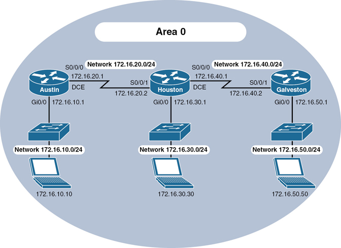
Figure 5-2 Network Topology for Single-Area OSPF Configuration
Austin Router
|
Starts OSPF process 1 |
|
Read this line to say, “Any interface with an address of 172.16.10.x is to run OSPF and be put into area 0” |
|
Read this line to say, “Any interface with an address of 172.16.20.x is to run OSPF and be put into area 0” |
|
Returns to privileged EXEC mode |
|
Saves the configuration to NVRAM |
OR |
|
|
Moves to interface configuration mode |
|
Enables OSPF area 0 on this interface |
|
Moves to interface configuration mode |
|
Enables OSPF area 0 on this interface |
|
Returns to privileged EXEC mode |
|
Saves the configuration to NVRAM |
Houston Router
|
Starts OSPF process 1 |
|
Read this line to say, “Any interface with an address of 172.16.x.x is to run OSPF and be put into area 0.” One statement will now advertise all three interfaces |
|
Returns to privileged EXEC mode |
|
Saves the configuration to NVRAM |
OR |
|
|
Moves to interface configuration mode |
|
Enables OSPF area 0 on this interface |
|
Moves to interface configuration mode |
|
Enables OSPF area 0 on this interface |
|
Moves to interface configuration mode |
|
Enables OSPF area 0 on this interface |
|
Returns to privileged EXEC mode |
|
Saves the configuration to NVRAM |
Galveston Router
|
Starts OSPF process 1 |
|
Read this line to say, “Any interface with an exact address of 172.16.40.2 is to run OSPF and be put into area 0” This is the most precise way to place an exact address into the OSPF routing process |
|
Read this line to say, “Any interface with an exact address of 172.16.50.1 is to be put into area 0” |
|
Returns to privileged EXEC mode |
|
Saves the configuration to NVRAM |
OR |
|
|
Moves to interface configuration mode |
|
Enables OSPF area 0 on this interface |
|
Moves to interface configuration mode |
|
Enables OSPF area 0 on this interface |
|
Returns to privileged EXEC mode |
|
Saves the configuration to NVRAM |
Configuration Example: Multiarea OSPF
Figure 5-3 shows the network topology for the configuration that follows, which demonstrates how to configure multiarea OSPF using the commands covered in this chapter.

Figure 5-3 Network Topology for Multiarea OSPF Configuration
ASBR Router
|
Moves to privileged EXEC mode |
|
Moves to global configuration mode |
|
Sets the router host name |
|
Enters loopback interface mode |
|
Assigns an IP address and netmask |
|
Sets a locally significant description |
|
Returns to global configuration mode |
|
Creates default route. Using both an exit interface and next-hop address on a GigabitEthernet interface prevents recursive lookups in the routing table |
|
Creates a static route to a null interface. In this example, these routes represent a simulated remote destination |
|
Creates a static route to a null interface. In this example, these routes represent a simulated remote destination |
|
Creates a static route to a null interface. In this example, these routes represent a simulated remote destination |
|
Enters interface configuration mode |
|
Enables OSPF area 0 on this interface. Also creates the OSPF routing process |
|
Returns to global configuration mode |
|
Enters OSPF configuration mode |
|
Sets the default route to be propagated to all OSPF routers |
|
Redistributes static routes into the OSPF process. This turns the router into an ASBR because static routes are not part of OSPF, and the definition of an ASBR is a router that sits between OSPF and another routing process—in this case, static routing |
|
Returns to global configuration mode |
|
Returns to privileged EXEC mode |
|
Saves the configuration to NVRAM |
ABR-1 Router
|
Moves to privileged EXEC mode |
|
Moves to global configuration mode |
|
Sets the router host name |
|
Enters loopback interface mode |
|
Assigns an IP address and netmask |
|
Sets a locally significant description |
|
Returns to global configuration mode |
|
Enters interface configuration mode |
|
Enables OSPF on this interface and creates the OSPF routing process |
|
Sets the priority for the DR/BDR election process. This router will win and become the DR |
|
Returns to global configuration mode |
|
Enters interface configuration mode |
|
Enables OSPF on this interface |
|
Returns to global configuration mode |
|
Returns to privileged EXEC mode |
|
Saves the configuration to NVRAM |
ABR-2 Router
|
Moves to privileged EXEC mode |
|
Moves to global configuration mode |
|
Sets the router host name |
|
Enters loopback interface mode |
|
Assigns an IP address and netmask |
|
Sets a locally significant description |
|
Returns to global configuration mode |
|
Enters interface configuration mode |
|
Places this interface into OSPF area 0 and enables the OSPF routing process |
|
Sets the priority for the DR/BDR election process. This router will become the BDR to ABR-1’s DR |
|
Enters interface configuration mode |
|
Places this interface into OSPF area 0 and enables the OSPF routing process |
|
Returns to global configuration mode |
|
Enters OSPF process 1 |
|
Makes area 1 a stub area. Type-4 and Type-5 LSAs are blocked and not sent into area 1. A default route is injected into the stub area, pointing to the ABR |
|
Returns to global configuration mode |
|
Returns to privileged EXEC mode |
|
Saves the configuration to NVRAM |
Internal Router
|
Moves to privileged EXEC mode |
|
Moves to global configuration mode |
|
Sets the router host name |
|
Enters loopback interface mode |
|
Assigns an IP address and netmask |
|
Sets a locally significant description |
|
Enters interface configuration mode |
|
Places this interface into OSPF area 1 and enables the OSPF routing process |
|
Enters interface configuration mode |
|
Places this interface into OSPF area 1 |
|
Returns to global configuration mode |
|
Enters OSPF process 1 |
|
Makes area 1 a stub area |
|
Returns to global configuration mode |
|
Returns to privileged EXEC mode |
|
Saves the configuration to NVRAM |
Configuration Example: Traditional OSPFv3
Figure 5-4 shows the network topology for the configuration that follows, which demonstrates how to configure traditional OSPFv3 using the commands covered in this chapter.
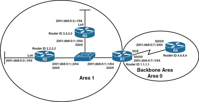
Figure 5-4 Network Topology for Traditional OSPFv3 Configuration
R3 Router
|
Enables the forwarding of IPv6 unicast datagrams globally on the router. This command is required before any IPv6 routing protocol can be configured |
|
Moves to OSPFv3 router configuration mode |
|
Sets a manually configured router ID |
|
Returns to global configuration mode |
|
Moves to interface configuration mode |
|
Configures a global IPv6 address on the interface and enables IPv6 processing on the interface |
|
Enables OSPFv3 on the interface and places this interface into area 1 |
|
Enables the interface |
|
Moves to interface configuration mode |
|
Configures a global IPv6 address on the interface and enables IPv6 processing on the interface |
|
Enables OSPFv3 on the interface and places this interface into area 1 |
|
Moves to global configuration mode |
|
Moves to privileged EXEC mode |
|
Saves the configuration to NVRAM |
R2 Router
|
Enables the forwarding of IPv6 unicast datagrams globally on the router. This command is required before any IPv6 routing protocol can be configured |
|
Moves to OSPFv3 router configuration mode |
|
Sets a manually configured router ID |
|
Returns to global configuration mode |
|
Moves to interface configuration mode |
|
Configures a global IPv6 address on the interface and enables IPv6 processing on the interface |
|
Enables OSPFv3 on the interface and places this interface into area 1 |
|
Enables the interface |
|
Moves to interface configuration mode |
|
Configures a global IPv6 address on the interface and enables IPv6 processing on the interface |
|
Enables OSPFv3 on the interface and places this interface into area 1 |
|
Enables the interface |
|
Moves to global configuration mode |
|
Moves to privileged EXEC mode |
|
Saves the configuration to NVRAM |
R1 Router
|
Enables the forwarding of IPv6 unicast datagrams globally on the router. This command is required before any IPv6 routing protocol can be configured |
|
Moves to OSPFv3 router configuration mode |
|
Sets a manually configured router ID |
|
Returns to global configuration mode |
|
Moves to interface configuration mode |
|
Configures a global IPv6 address on the interface and enables IPv6 processing on the interface |
|
Enables OSPFv3 on the interface and places this interface into area 1 |
|
Enables the interface |
|
Moves to interface configuration mode |
|
Configures a global IPv6 address on the interface and enables IPv6 processing on the interface |
|
Enables OSPFv3 on the interface and places this interface into area 0 |
|
Assigns a clock rate to this interface |
|
Enables the interface |
|
Moves to global configuration mode |
|
Moves to privileged EXEC mode |
|
Saves the configuration to NVRAM |
R4 Router
|
Enables the forwarding of IPv6 unicast datagrams globally on the router. This command is required before any IPv6 routing protocol can be configured |
|
Moves to OSPFv3 router configuration mode |
|
Sets a manually configured router ID |
|
Returns to global configuration mode |
|
Moves to interface configuration mode |
|
Configures a global IPv6 address on the interface and enables IPv6 processing on the interface |
|
Enables OSPFv3 on the interface and places this interface into area 1 |
|
Enables the interface |
|
Moves to global configuration mode |
|
Moves to privileged EXEC mode |
|
Saves the configuration to NVRAM |
Configuration Example: OSPFv3 with Address Families
Figure 5-5 shows the network topology for the configuration that follows, which demonstrates how to configure OSPFv3 address families using the commands covered in this chapter.

Figure 5-5 Network Topology for OSPFv3 Address Families Configuration
R1 Router
|
Enables the forwarding of IPv6 unicast datagrams globally on the router. This command is required before any IPv6 routing protocol can be configured |
|
Moves to interface configuration mode |
|
Assigns an IP address and netmask |
|
Configures a global IPv6 address on the interface and enables IPv6 processing on the interface |
|
Moves to interface configuration mode |
|
Assigns an IP address and netmask |
|
Configures a global IPv6 address on the interface and enables IPv6 processing on the interface |
|
Enables the interface |
|
Returns to global configuration mode |
|
Enables OSPFv3 router configuration mode for the IPv4 or IPv6 address family |
|
Configures the router to send a syslog message when an OSPFv3 neighbor goes up or down |
|
Configures a fixed router ID |
|
Enters IPv6 address family configuration mode for OSPFv3 |
|
Prevents interface loopback 0 from exchanging any OSPF packets, including hello packets |
|
Enters IPv4 address family configuration mode for OSPFv3 |
|
Prevents interface loopback 0 from exchanging any OSPF packets, including hello packets |
|
Returns to OSPFv3 router configuration mode |
|
Returns to global configuration mode |
|
Moves to interface configuration mode |
|
Enables OSPFv3 instance 1 with the IPv6 address family in area 0 |
|
Enables OSPFv3 instance 1 with the IPv4 address family in area 0 |
|
Moves to interface configuration mode |
|
Enables OSPFv3 instance 1 with the IPv6 address family in area 0 |
|
Enables OSPFv3 instance 1 with the IPv4 address family in area 0 |
|
Returns to global configuration mode |
|
Returns to privileged EXEC mode |
|
Copies the running configuration to NVRAM |
R2 Router
|
Enables the forwarding of IPv6 unicast datagrams globally on the router. This command is required before any IPv6 routing protocol can be configured |
|
Moves to interface configuration mode |
|
Assigns an IP address and netmask |
|
Configures a global IPv6 address on the interface and enables IPv6 processing on the interface |
|
Moves to interface configuration mode |
|
Assigns an IP address and netmask |
|
Configures a global IPv6 address on the interface and enables IPv6 processing on the interface |
|
Enables the interface |
|
Returns to global configuration mode |
|
Enables OSPFv3 router configuration mode for the IPv4 or IPv6 address family |
|
Configures the router to send a syslog message when an OSPFv3 neighbor goes up or down |
|
Configures a fixed router ID |
|
Enters IPv6 address family configuration mode for OSPFv3 |
|
Prevents interface loopback 0 from exchanging any OSPF packets, including hello packets |
|
Enters IPv4 address family configuration mode for OSPFv3 |
|
Prevents interface loopback 0 from exchanging any OSPF packets, including hello packets |
|
Returns to OSPFv3 router configuration mode |
|
Returns to global configuration mode |
|
Moves to interface configuration mode |
|
Enables OSPFv3 instance 1 with the IPv6 address family in area 0 |
|
Enables OSPFv3 instance 1 with the IPv4 address family in area 0 |
|
Moves to interface configuration mode |
|
Enables OSPFv3 instance 1 with the IPv6 address family in area 0 |
|
Enables OSPFv3 instance 1 with the IPv4 address family in area 0 |
|
Returns to global configuration mode |
|
Returns to privileged EXEC mode |
|
Copies the running configuration to NVRAM |
R3 Router
|
Enables the forwarding of IPv6 unicast datagrams globally on the router. This command is required before any IPv6 routing protocol can be configured |
|
Moves to interface configuration mode |
|
Assigns an IP address and netmask |
|
Configures a global IPv6 address on the interface and enables IPv6 processing on the interface |
|
Moves to interface configuration mode |
|
Assigns an IP address and netmask |
|
Configures a global IPv6 address on the interface and enables IPv6 processing on the interface |
|
Enables the interface |
|
Returns to global configuration mode |
|
Enables OSPFv3 router configuration mode for the IPv4 or IPv6 address family |
|
Configures the router to send a syslog message when an OSPFv3 neighbor goes up or down |
|
Configures a fixed router ID |
|
Enters IPv6 address family configuration mode for OSPFv3 |
|
Prevents interface loopback 0 from exchanging any OSPF packets, including hello packets |
|
Enters IPv4 address family configuration mode for OSPFv3 |
|
Prevents interface loopback 0 from exchanging any OSPF packets, including hello packets |
|
Returns to OSPFv3 router configuration mode |
|
Returns to global configuration mode |
|
Moves to interface configuration mode |
|
Enables OSPFv3 instance 1 with the IPv6 address family in area 0 |
|
Enables OSPFv3 instance 1 with the IPv4 address family in area 0 |
|
Moves to interface configuration mode |
|
Enables OSPFv3 instance 1 with the IPv6 address family in area 0 |
|
Enables OSPFv3 instance 1 with the IPv4 address family in area 0 |
|
Returns to global configuration mode |
|
Returns to privileged EXEC mode |
|
Copies the running configuration to NVRAM |