
THE OBJECTIVE OF THIS CHAPTER IS TO ACQUAINT THE READER WITH THE FOLLOWING CONCEPTS:
Computer hardware terms, and advantages of different types of system architecture
Functional introduction to the OSI model and its relationship with TCP/IP
Methods of creating different types of area networks (LAN, WAN, PAN, WLAN)
Network addressing and methods for routing data communications
Different types of networking equipment and their purposes
Network services including DHCP, Domain Name System, and firewalls
An introduction to network management

A functional introduction of the OSI model will be presented with its relationship to the TCP/IP model used in the real world. Using the OSI model as the backdrop, we will discuss the functions of different types of network equipment. It is important for CISAs to understand the purpose and capabilities presented by the operating systems, routers, switches, firewalls, and other peripherals. The goal of this chapter is to provide a general understanding of how the infrastructure could be assembled in a manner that fulfills most of the internal control requirements.
We'll wrap up the chapter with a discussion on network management because auditors are expected to understand network analyzers, capacity planning, and monitoring techniques. Several of the points regarding network security are covered again in Chapter 7, "Information Asset Protection." The purpose of this chapter is to provide you a firm foundation in networking technology.
All computers are not created equal. The differences in architecture have a substantial impact on performance and system security. However, every computer has three basic types of components:
- Central processing unit
The first component group centers around the central processing unit, also known as the CPU. The CPU performs mathematical calculations with the assistance of an internal arithmetic logic unit, a high-speed memory cache, and working memory space known as random access memory (RAM). Data stored in random access memory is erased when power is turned off.
- Input/output
The second component group provides input and output to peripheral devices such as keyboards, monitors, and disk drives. This input and output channel is used to transmit data to and from the CPU for processing. Computers with a simple architecture may use a common channel for all communication with the CPU. This channel may be an individual connector or a shared data bus of several devices.
- Data storage
The third component group is data storage. Every computer requires additional storage space, such as a hard disk. Data storage may be fixed in a semipermanent location or removable. When a computer is turned on, the initial startup process is executed from internal programmable chips and data storage disks. This startup function is called boot strapping (boot) or initial program load (IPL). The operating system is loaded from data storage, along with device driver information for the Basic Input/Output System (BIOS). The system is available for use after completion of the boot, or IPL, process.
Figure 4.1 is a general diagram illustrating the architecture of a computer. Notice the CPU on the upper left. The CPU is the brains of the system and is attached to all of the other components with a string of electrical conductors. This string of conductors is called the system data bus, which is represented as the lines drawn across the middle of the diagram. Bus is an electrical term that means a shared electrical path. The CPU could not run effectively without the support of solid-state memory, known as random access memory (RAM). Random access memory is not as fast as the CPU. A special type of superfast memory is used to buffer between the CPU and RAM to help the CPU run at maximum speed. This high-speed CPU buffer memory is known as cache. The heart of computer processing occurs between the CPU, cache, and RAM. Other devices are attached to the data bus through computer expansion slots and interfaces. The disk drives and network each have their own electronic interface or add-in card connected to the data bus. This is how the information flows to and from the electronic components.

Integrated circuits of the CPU can perform mathematical calculations faster than we can think or act. In fact, a computer with a single CPU will spend a great deal of time waiting for human input. The CPU can therefore support light processing for several users at one time with little delay. The process of CPU sharing for multiple users is called time-sharing (see Figure 4.2). Each user or system process receives a tiny segment of time for processing their request. Only one request is processed at a time. All other processing requests are parked in memory, awaiting their turn. Each processing request is serviced by generating a system interrupt. The CPU halts on interrupt and swaps processing with the task stored in memory. This process is similar to how you handle interruptions when the telephone rings. The computer is presumed to be running so fast that the other users do not notice any significant delay.

Computers with single processors have two major drawbacks. The first issue is related to systems security. Each system interrupt halts any security software that is running and allows the task to be processed before restarting the security software. The second drawback is the CPU bottleneck created by processor-intensive activities of database and graphics-rendering software.
Multiprocessor computers and computers based on multicore CPUs are designed to deal with the demands of process-intensive applications. Multiprocessor systems are ideal for high-security environments since the security software will be able to run without any interruption. The processor may still perform time-sharing functions for multiple users; however, the load is allocated across multiple CPUs. Figure 4.3 shows a typical multiprocessor architecture.
Tip
Security software on a computer with a single CPU is halted during each system interrupt request to allow the next task to be processed. The security software is then restarted and halted again between each request by another program to run on the single CPU chip. Computer interrupts occur in normal operation hundreds or thousands of times per second.
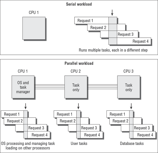
When the multiprocessor system is booted, the first processor accepts the responsibility of running system functions for control, input, and output. The first CPU schedules processing tasks across the other CPUs. These tasks include the dedicated servicing of requests from programs such as an SQL database on CPU 2, running dedicated monitoring software without any interruptions on CPU 3, and off-loading miscellaneous user requests to CPU 4.

The operating system becomes a resident on CPU 1 and performs hardware checks for input and output. The second processor loads as a task processor only. Each additional processor does the same. This allows the first CPU to have uninterrupted control of the system operations, including security, while the other CPUs perform problem-solving tasks in response to user requests.
Figure 4.4 shows how the workload is stacked and processed through the CPUs. Notice that each CPU has a small stack of tasks that are each in different phases of processing. This stacking of tasks is referred to as pipelining. Think of it as a pipeline full of people standing at your door and wanting you to do work for them.
A single CPU would be maxed out with a small pipeline. The multiprocessor system, on the other hand, designates one CPU to be the equivalent of a manager, while the other CPUs each process their own pipeline full of requests. In the real world, this could look like a room full of people talking on the phone, smoking cigarettes, drinking coffee, and answering email all at the same time. As you're aware, a group of people can smoke a lot more cigarettes and process a lot more email than one person. The same can be said about computers with multiple processors.
Multiprocessor systems can perform high-security processing with a separation of duties. Individual processors could be dedicated to perform security functions without interruption. The CPU can be programmed to ignore interrupt requests. Ignoring a processing request is referred to as interrupt masking. Interrupt masking is useful for ensuring that high-priority tasks are not interrupted.
In this section, you will look at various computer operating systems, as well as how to determine the best computer for you. In addition, you will compare some of their capabilities and look at supervisory versus problem states. Finally, you will look at data storage and port controls more closely.
Every computer uses some sort of operating system (OS) to control the hardware. Each make and model of computer hardware is slightly different. For example, the processor type might be different, or the computer might use a specialized disk drive subsystem.
Computer programs of the 1950s and 1960s were not as portable as they are today. The old computers required the programmer to write a unique program for each model of system. As time progressed, computer software evolved with the development of new programming languages and then new operating systems.
The Unix operating system was created by Ken Thompson to run a computer program called Space Travel. The more advanced operating system used in the 1960s was the Multiplexed Information and Computing Service (Multics). This is why you may encounter references to Multics in older Unix documentation. Thompson noticed two problems while trying to run the space travel program.
First, the time-sharing design of running Multics on the available hardware did not give Thompson's program the dedicated speed necessary for it to run fast enough. So Thompson decided to delete the Multics time-sharing functions. The revamped single-user operating system was named the Uniplexed Operating and Computing System (Unics). It was later renamed Unix after some multiuser capabilities were re-added.
The second problem was software portability across hardware. Each time Thompson attempted to move the space travel program from one computer to another, it was necessary to rewrite the program to accommodate differences in hardware. Dennis Ritchie joined Thompson to work on projects for software portability across different hardware. They created a series of programming languages known as B, and then C. This is the same C programming language that you hear about today. All later additions to the original C programming language bear the designators C+, C++, and C# (also known as C Sharp). Chapter 5, "Life Cycle Management," covers more details on programming.
Modern computers use a more refined operating system. You will typically use an operating system designed for the type of hardware you intend to use. IBM's OS MVS is common in the IBM mainframe world, whereas Unix is run on a variety of systems. Microsoft Windows is popular for its relatively low initial cost and widespread availability. The Apple Mac OS has a smaller, yet growing, market share with a devoutly dedicated following in the graphics and motion picture industry.
Each of these operating systems shares common traits. The operating system vendor works with the hardware manufacturer to create specialized hardware support within the operating system. The application programmer simply compiles their program for a particular operating system. All the user needs to do is to match their desired application software to the operating system, and then match the operating system to the available hardware.
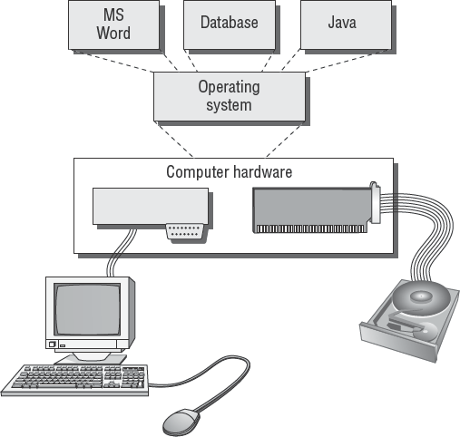
Figure 4.5 shows what a common computer operating system looks like.
Every commercial-grade computer OS provides at least the following functions:
Provides a user interface to the computer. The interface is often called a shell. This is the command line or graphical interface supporting the directions to the computer.
Manages security and event logging during the interaction between a user and the computer hardware.
Provides a common software platform to run application programs. Computer programs run on top of the operating system. The operating system acts as a translator between the program and the hardware. Application programs no longer need to be rewritten for hardware changes if using the same OS.
Provides an organized file system to store and retrieve data.
Provides a method of input and output to various devices, including disk drives, network connections, printers, and video displays.
Coordinates internal communications between programs and processing of tasks by the CPU.
May provide no security, primitive login security, or advanced security to protect the data and programs from harm.
Operating systems can be designed to support a single user or multiple users. You can run software slowly in a batch of requests (set of requests, also known as batch mode) or in smaller and faster batches to simulate real-time transactions.
Computers can function in an ever-increasing variety of roles. Some computers are designed for special-purpose functions, for example, the Palm handhelds or new 3G integrated wireless phones. Many computers are designed for general-purpose use as a desktop or laptop computer. Table 4.1 lists some of the typical functional roles that computers fulfill.
Table 4.1. Typical Computer Roles
Computers come in a variety of sizes and prices, based on their processing power and throughput. (Throughput is a measure of how much information passes through the system in a specific period of time.) There are four major classes of computer systems: supercomputers, mainframe computers, minicomputers, and personal computers.
Supercomputers are designed for intense scientific calculations. A supercomputer would be used to calculate the incredible details of a nuclear reaction and to trace the particles through their life cycle, for example. Supercomputers are not measured in size, but instead by the lightning speed at which transactions can occur. They tend to be specialized systems running large-scale simulation and analysis programs. The mission of supercomputers is to solve complex mathematical calculations. Supercomputers are not used for processing a business database or corporate financial records.
Mainframe computers are large, scalable, general-purpose systems designed to support incredible volumes of data. These are the large boxes you would see in a traditional data center. A single mainframe computer could be as small as a filing cabinet or as large as a roomful of refrigerators, all depending on its configuration.
Mainframes have the advantage of being able to process massive amounts of data in parallel, with incredible throughput. These systems are capable of multithreading thousands of programs simultaneously. Multithreading allows programs to be executed in parallel to minimize idle time within the processors. Mainframe computers have provided the role model for other systems to follow.
Prices range from $50,000 to tens of millions of dollars. A mainframe offers several advantages to those who can afford one, including the following:
Rock-solid virtual machine that can partition resources into smaller environments. You can easily set up one mainframe to act as 300 to 5,000 PC servers, without the administrative headache.
Outstanding security. The internal system-partitioning controls have built-in segregation of duties with multiple layers of security. Internal system control reporting is excellent.
Lower software licensing costs. Software licenses are based on the physical machine or CPU. The mainframe software-licensing model provides a wonderful economy of scale with the added ability to share the license across multiple users inside the virtual machine (VM) feature. This can save hundreds of thousands of dollars.
Excellent financial-reporting controls. Most mainframes were designed to bill individual usage as a profit center. You can practically charge the user for each electron in the processing of their job across each device used.
Very high throughput with stability that is measured in years.
Mature 40-year arsenal of system support programs. Mainframes are highly respected for their vast libraries of programs designed for advanced internal control.
IBM is the dominant vendor in the mainframe market, with 90 percent of the market share. Sales of mainframe systems are increasing in response to issues of control and economies of scale. For large operations, the mainframe is proving again to be an economical choice. Its high-volume parallel throughput cannot be matched by smaller systems.
Midrange computers, also referred to as minicomputers, are designed to be operated by individual departments or smaller organizations. The upper end includes the IBM AS/400 and newer z9 class which are designed to be either a mainframe or midrange computer, depending on the configuration selected by the buyer. PC style super servers with multiple processors from IBM, Dell, HP and Sun represent the most common midrange systems.
Unix is also popular as a midrange operating system. Unix lacks several of the partition and security controls of a mainframe environment, but it does have many of the important job-processing features at a lower overall operating cost. Microsoft's operating system is used by organizations operating without system programmers. The later customers let Microsoft control their system's design, security and overall cost structure.
Microcomputers are small systems that can be implemented as a PC, notebook, or personal digital assistant (PDA). Most microcomputers are designed to service the needs of an individual user. The operating system may have multiuser capability if running on sufficient hardware to support the requirement.
Microcomputers can run a variety of general-purpose operating systems, including Unix, Microsoft Windows, and the Apple Mac OS X. Microcomputers were invented to meet users' demands for more control over their individual processing needs. At the time, mainframes were dedicated to large-volume batch processing and ignored many of the user requests for processing.
The explosion of microcomputers has created a growing awareness of all the internal security controls that are missing. The biggest problem with microcomputers is the lack of mainframe-grade controls.
Tip
As an IS auditor, you may hear the term MIPS. MIPS is an acronym for millions of instructions per second. It is often used as a numerical claim of system performance with little regard for the real-world environment. MIPS is actually a highly subjective number used to hype a particular computer. The true measure of performance is system throughput, measured in the total volume of transactions processed from end to end.
It is your job as an auditor to determine whether the IT environment is aligned to the business requirements. Figure 4.6 is a simple graphical representation of the differences in capabilities among mainframes, minicomputers, and microcomputers.
The dominant criteria used for system selection is the desired throughput. Another area of interest is the level of internal control required by the user.

Note
Chapter 6, "IT Service Delivery," covers capacity and workload management issues.
Figure 4.7 demonstrates the simple hierarchy of the classes of computer systems and their market share.
At the top of the pyramid is a mainframe, which has the highest level of capability. Mainframes are not as numerous because of initial purchase cost. In the middle is the midrange computer for individual departments or a smaller organization. Midrange-processing computers are extremely popular for running databases such as Oracle Financials, SAP Manufacturing, or Oracle's PeopleSoft. At the bottom are the vast numbers of PC workstation users with a lower-end processing requirement.
With all this computer processing, it is necessary to ensure adequate management controls.

The first level of control in the computer is the privileged supervisory user. Every computer needs a special user account representing the highest level of authority, for the purpose of controlling change. This supervisory user is also known as the superuser, root user, or administrator. The names may be different, but the purpose is the same. This privileged user is responsible for configuration, maintenance, and all ongoing administrative tasks. The supervisory user is often exempt from the internal controls imposed on other users. This exemption gives the administrative user much more power and poses a unique challenge to system control.
The typical user spends their day trying to get the computer to solve problems. This common user has limited access and is subject to a variety of system controls. All office workers fall into this second category.
The technology world has created simple terminology to illustrate the differences between the supervisory user and everybody else. All computers operate in these three basic operating states:
- Supervisory state
The system security front-end is not loaded. All processing requests are run at the highest level of authority without any security controls.
- General user, or problem, state
Security is active, and the computer is supposed to be solving problems for the user.
- Wait state
The computer is busy working to service other tasks and unable to respond to another user request.
The goal of a computer hacker is to gain problem state access (general user access) and convert it into supervisory state access (supervisor access). After the hacker gains access to the system, they will use a variety of attempts to break into supervisory control. The hacker may use invalid parameters to cause a supervisory-level program to fail. Some programs, such as password-change utilities or print queue management, may default to a supervisory-level command prompt upon failure. This allows the hacker to bypass the normal security front-end. An attacker or poorly written software program can trigger an overload of processing requests, which creates an extended series of wait states. When the computer is overloaded with requests, the condition is called a denial of service. The computer is too busy to help the user.
Software parameter control is important for multiple reasons. As stated, invalid software parameters may be used by a hacker. Another risk is valid software parameters that should be run only for a special administrative purpose. For example, the command mysql-i instructs the MySQL database manager to reinitialize the database tables, which would erase any current data. Access to the command line should be restricted. It is much safer to design menus or restricted user interfaces to ensure security.
Adequate data storage is an important issue in a production environment. Controls need to be in place to ensure safe storage of data. The auditor is concerned with how many copies of the data exist and the controls that are in use. It is amazingly easy to lose control over electronic data. As an auditor, you would be concerned about both the integrity and security mechanisms in use by the client.
Tape management systems (TMSs) and disk management systems (DMSs) are used to help retain control over data files. These automated systems can provide label and tracking management. The security of the data is always an issue. Good media management practices include the ability to rapidly identify every version of data under the organization's control with the label, location, and status of each piece of media that data is stored on. This is the job function of a good tape or media librarian.
The following are some of the common types of data storage media:
- Magnetic hard disk
These rigid, metal disks mounted inside a sealed disk drive are high-speed devices that are designed for permanent installation. Capacity can go from gigabytes to terabytes. Hard disks are the most common method of online data storage. By using special software, you can cluster drives into high-availability storage arrays. An example is RAID. Depending on who you ask, the definition is either Redundant Array of Inexpensive Disks or Redundant Array of Independent Disks. A vendor might use the latter to facilitate a higher sales price.
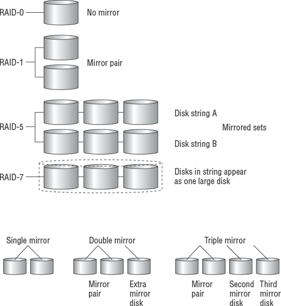
Let's talk about capacity planning for a RAID system. RAID level 0 (zero) offers no protection, but RAID level 1 provides full redundancy using total duplication. Full duplication is referred to as disk mirroring.
The initial issue for RAID-1 was cost and capacity sizing. If you had a total of 500 gigabytes of disk and installed RAID-1, the result was a maximum of 250 usable gigabytes. RAID 1 used twice the disk space for half the capacity. Next you had to subtract room for the 20 percent minimum free disk space needed to run the operating system, so now the RAID-1 usable capacity was only 200 gigabytes out of 500 gigabytes. Some customers liked the idea but others were confused. This led to creating other methods for RAID in an attempt to accomplish redundancy equivalent to RAID-1 at a lower cost. Lower cost meant using fewer disk drives.
RAID levels 2, 3, and 4 are considered operational failures. The time to rebuild damaged data took too long after a single disk failure. RAID uses multiple disks connected into disk strings. The failure of a single disk is not supposed to be a problem. Two or more disk failures in the same disk string would kill the RAID system.
RAID level 5 is considered a successful alternative. It uses fewer disks than RAID-1 with more usable space. Most drive arrays sold in the market feature a RAID-5 design.
RAID level 6 was another operational failure. The next design was more successful. RAID level 7 uses independent disks with a very high transfer rate. In RAID-7, it's possible to combine multiple disks into a single spanning partition operating at much higher speeds.
Hybrid RAID systems have also entered the market. These crown jewels implement two different RAID methods into one system:
Hybrid RAID 0+1 systems implement two sets of RAID-0 disks into two mirrored strings running under RAID-1.
Hybrid RAID 5+1 systems put two RAID-5 disk strings into a fully duplicated pair. The pair is extra redundant because two RAID-5 disk arrays are duplicated as two RAID-1 sets for a double redundant approach.
Depending on your system hardware capabilities, you can have single mirror, double mirror, or triple mirror disks:
Single mirror is two disks (or sets of disks, also known as disk arrays) holding two mirror image copies of the same data. The disks function independently if one fails. This is the typical RAID-1 implementation.
Double mirror has three disk sets holding three copies of the same data. Each disk set functions independently for extra redundancy.
Triple mirror uses four sets of disks offering quadruple copies of data. IBM has offered this feature for about two decades. The extra disk set can be unpaired to allow live backups during the peak usage time in your workday. System administrators refer to this type of backup process as unmounting, breaking the mirror, or remounting disk to tape. Triple mirror ensures that you never have fewer than three copies of live data online, and you have an incredibly low risk of disk failures. After backup is completed, the fourth set is remirrored to make the data current.
You are expected to understand a few basic differences between RAID levels. Table 4.2 covers these basic differences. You could copy and then cut out the table to be used as flash cards for memorization.
Table 4.2. Description of RAID Operating Levels
RAID Level | Operating Mode | DESCRIPTION |
|---|---|---|
RAID-0 | Striping across multiple disks | Not fault-tolerant. This design simply makes several small disks appear as one big disk. |
RAID-1 | Mirroring | Excellent way of creating two live copies of the data. Most expensive to implement; cuts disk space in half. |
RAID-2 | Hamming error-correcting code (ECC) | Interweaves data across multiple drives with error-correcting parity code. Too resource intensive. |
RAID-5 | Block-level distributed parity | This method is commonly used in disk arrays. The design uses less disk space than RAID-1 for the same amount of usable storage. |
RAID-7 | Optimized asynchronous | Uses independent, asynchronous transfer mode of very high transfer rates. Rather expensive. |
RAID 0+1 | High transfer rate | Combines two sets of RAID-0 disks with a RAID-1 mirroring design. The objective is to increase performance. Unfortunately, a two-drive failure can cause major data loss. |
Figure 4.8 is a basic diagram of the different RAID systems. Notice that individual disks are attached to form disk strings.
- Magnetic soft disk
This includes floppy, Zip, and Jaz drives. They are designed with a soft read-write disk inside a hard shell. This highly portable media is available in capacities from 1MB to more than 4GB.
- Magnetic tape
Available in reel or cartridge design, magnetic tape is the most common method of long-term data storage. Its original use was in 2400bpi (bits per inch) tape mounted on a reel. Capacities have grown dramatically. With higher capacity came the cartridge version. Cartridge tapes can have an internal design similar to a reel-to-reel cassette or a single-reel design like the old 8-track tape. Examples include digital linear tape (DLT), 4mm–8mm Digital Data Storage (DDS), 9-track reel, 3480 and newer 3590 cartridge, VHS video, DVD video, and others. High-quality tapes can be expensive when you buy the hundreds of blanks necessary to properly stock a backup library. Different backup vendors require very particular hardware devices with special software for backups. Frequently, tape media is portable only to identical tape drives with identical software from the same manufacturer. A malfunctioning tape drive can permanently destroy the tape and all the data it contains.
Tapes offer the luxury of allowing the administrator to back up 100 percent of the operating system, its invaluable configuration data, complete programs, and user data in one process. Individual files or the whole system can be fully restored from tape to match a specific point in time from years ago.
- Read-only memory
Programmable read-only memory (ROM) is used to permanently record software programs on integrated circuits (chips). The advantages are lightning-fast program loading and solid-state nonvolatile storage without moving parts. Programming is accomplished by using specialized equipment to burn or fuse microscopic links inside the semiconductor chip. Once programmed, the software becomes permanent and cannot be changed or erased. This can be either a product limitation or security advantage depending on the intended purpose. To upgrade, you must physically replace the ROM chip. These chips are not portable between devices.
- Flash memory
A special type of electronically erasable programmable read-only memory (EEPROM) is used in computers for flash BIOS, video cameras, USB handheld removable memory sticks, and newer portable devices. These are designed to supplement or replace magnetic disks. Unfortunately, the flash devices are easily lost or stolen. The small size and high capacity can be a real security concern. Some of these devices are bootable and can bypass your security controls. They have limited portability but are improving daily.
- Optical CD-ROM
Used to store read-only data or music, optical CD-ROMs have a typical capacity of 80 minutes of audio or 700MB of data. This is an excellent method for archiving files or data backup when using a CD disk burner. It is a highly portable media. Blank disks are inexpensive and may be referred to as WORM (write once, read many).
- Optical CD-RW
A rewritable version of the old CD-ROM design, these disks can be erased and rewritten just like all other magnetic disk media. If you used the old WORM nomenclature, this would be called a WMRM disk (write many, read many). Today nobody calls them anything but CD-RW.
- Optical DVD
This is a newer variation of the optical CD with higher capacity measured in gigabytes. The DVD is commonly used for video or data storage. This is a highly portable media.
Computers use interfaces to connect different types of hardware, also called accessories. According to the Institute of Electrical and Electronics Engineers (IEEE), an interface is a combination of physical design characteristics, voltages, electrical signals, and a protocol for communicating. The term protocol refers to a standard procedure or rule used to organize the communication process. Common computer slang may refer to the physical interface connector as a computer port. A common example is the USB hardware port.
Tip
Hospitals refer to standard procedures for treating a patient as the protocol. This definition is similar in meaning to the procedures a computer uses to process communication requests.
Every security professional is acutely aware of how physical access can bypass logical security controls. Physical input/output (I/O) ports provide an avenue for an individual to gain a higher degree of system access. The simultaneous connection of a modem and network card creates an unregulated pass-through opportunity that can circumvent perimeter defenses. As an auditor, you would want to see what controls have been implemented regarding physical access to input/output ports.
Microcomputers are particularly susceptible to port access via the keyboard, USB, RS-232, or network connection.
Note
The ISACA CObIT contains a section covering physical security controls for servers, routers, and other high-value network devices.
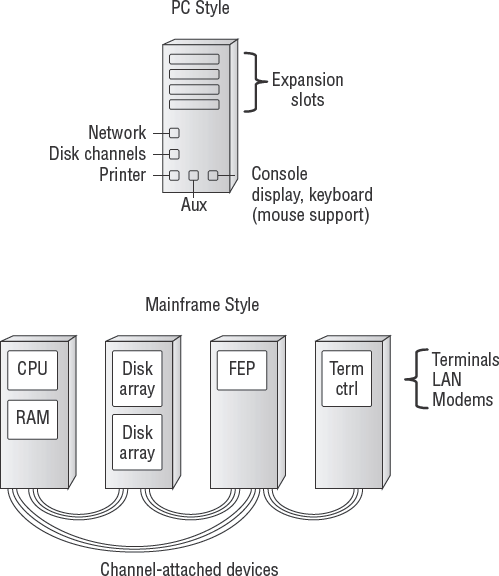
Figure 4.9 shows the basic computer ports. Notice the PC ports for keyboard, video, printer, and serial attached devices. The mainframe has similar ports that are distributed between several large equipment chassis. No matter where they're located, all of the ports must be protected.
Computers communicate over these I/O ports to a variety of storage devices. Physical security controls are intended to protect the physical ports. Logical controls are used to protect data communications. A logical control is usually implemented as a software program control.
A second type of computer interface is the software operating system port. These are commonly referenced in discussions about data communication, programming, and networking. Software ports (or sockets) function similarly to hardware ports. The software port does not have any physical hardware. Instead, it exists as simply a reference location, or buffer, for software to send data during transmission. As data arrives at the designated software port, another program is waiting for it. The program detects new data and processes it by using whatever set of rules have been designated within its protocol. Different requests will be processed by using different rules as specified in their unique protocol.
Each software port has a designated function assigned to it by its programmer. To promote compatibility, IEEE designated the usage (protocol) for the first 1,023 software ports used in the TCP/IP protocol. Visualize these as post office mailboxes. Each mailbox represents a different destination. The protocol in business is for people to pay bills after an invoice arrives in their mailbox. The payment is sent back using a return address. A computer using the File Transfer Protocol (FTP) sends data on port 21, as per its protocol standard. Terminal login (telnet) uses port 23 for its communications. This port design provides an orderly method of flow control between programs.
Software ports have to be protected too. The most common methods involve making detailed settings in the software configuration. Unfortunately, it's common for a software vendor to set the factory default, which uses insecure promiscuous settings. The vendor's intention is to eliminate calls for installation assistance to their help desk. This is why vendors often compromise your safety by requiring new software to be installed with the unrestricted access privileges of the root user or system administrator. It ensures that their software installs while leaving the remaining security consequences for someone else to deal with.
Warning
Beware of default settings. Richard Feynman was a bright physicist who worked at the secretive Los Alamos research labs during the development of the first atomic bomb. Using his brilliant powers of observation, Feynman deduced how to discover portions of safe combinations by detecting the tumbler's position after the safe's lock was opened by someone else. One day, a locksmith opened a safe within minutes after everyone thought the combination was lost. Feynman set out to discover the locksmith's secret. He spent several weeks building rapport with the locksmith. Then one day he asked the big question, "How did you open the safe?" The locksmith replied, "I called the manufacturer and asked for the default combination used when the safe was originally shipped." You can read more fascinating stories in the book Surely You're Joking, Mr. Feynman! (W.W. Norton & Company, 1997). Computer software vendors publish their default settings in technical books and training manuals and on the Internet for the whole world to see.
A second level of protection is provided by blocking access to software ports via a firewall. Chapter 7 discusses firewalls.
One of the best methods of illustrating software communication is the Open Systems Interconnect (OSI) model. The model is intended to demonstrate the activities that occur by using a method of hierarchal layers.
In the early 1980s, the International Organization for Standardization (ISO) was busy creating a new data communications model. Its intention was to build the next generation of communications protocols to replace both proprietary protocols and the de facto Transmission Control Protocol/Internet Protocol (TCP/IP). In the end, the cheaper TCP/IP protocols won the battle.
Many customers had no interest in paying for the cost of developing the Open Systems Interconnect (OSI) protocol. The OSI model is still used as a network training tool. This model stratifies data communication into seven distinct layers. Each layer provides a unique function in support of the layer above.
We are going to walk through the OSI model layer by layer and compare each function to the TCP/IP protocol model. The seven layers of the OSI model are as follows:
Physical layer
Data-Link layer
Network layer
Transport layer
Session layer
Presentation layer
Application layer
Let's start with a simple memory trick to remember each of the OSI layers in proper order (see Figure 4.10). My favorite mnemonic is Please Do Not Throw Sausage Pizza Away (PDNTSPA).
Note
We have been using this mnemonic for two decades. This mnemonic holds a unique association with a TCP/IP memory aid.

Each of the first letters relates to the first letter of an OSI layer, working your way up from the bottom. It is in your best interest to learn how to draw the OSI model and these layers from memory. You will find it helpful on your CISA exam. You will also find it helpful during discussions when you're trying to uncover the details about a particular product. It will impress clients.
The second, related mnemonic (see Figure 4.11) is No Interest Having Anchovies (NIHA). Once again, each letter refers to a layer of the official DoD TCP/IP model, working up from the bottom.

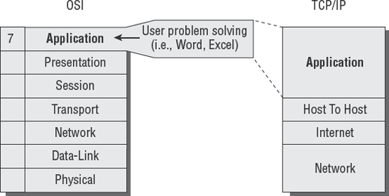
Let's review the basic OSI process for handling data. The top layer is where your application is running. The lower layers process the request and prepare the data for transmission as it works its way down to the bottom. When it reaches the bottom of the OSI model, the data has been broken down into electrical signals.
These electrical signals will be received by the other computer. Upon receipt, the transmission headers are stripped off. The remaining data message is passed to the application software running on the other computer. Figure 4.12 shows how this looks.

Now that you understand in general how data is transmitted when using the OSI and TCP/IP models, let's go inside the individual layers, one by one.
The Physical layer defines physical requirements in the cables and voltages (see Figure 4.13). This layer specifies functional specifications for creating, maintaining, and deactivating an electrical link between systems. Wireless transmitters substitute radio signals for the physical cable connection. Similarly, lasers substitute flashes of light to simulate electrical signals over fiber-optic cable.

The Data-Link layer (see Figure 4.14) focuses on establishing data communications via hardware device drivers and their transmit/receive function. Layer 2 provides flow control, error notification, and the order sequence during transmission.

Communication in layer 2 is established between each network card's Media Access Control (MAC) address. A MAC address is a burned-in serial number that is unique to every network card ever manufactured. The address is unique because it uses the manufacturer's ID and the board serial number. Each computer uses the MAC address for "to" and "from" communications within the same broadcast domain (layer 2). You can view the MAC address on your computer by using the following software commands:For Microsoft Windows, type ipconfig /all at the command line in the DOS command box.
In Unix, type ifconfig -al at the command-line prompt.
The computer will display something like what you see in Figure 4.15.

Every device on every network is supposed to have a unique MAC address. Imagine in the office how two people with the exact same name or exact same email address would create a communication conflict. The same is true of MAC addresses. In OSI layer 2, the computers communicate by sending messages to each other's MAC address.
The combined group of MAC addresses on the same network is referred to as a broadcast domain. Domain refers to scope boundaries of items located under the same controlling influence. Domains indicate relationships within the same general space. Computers in the same broadcast domain will hear (or see) all the traffic of the other computers.
Broadcast domains are no more than a noisy shouting match between computers on the same subnet. Every computer in that segment will hear every conversation from all the computers. For example, Microsoft NetBIOS is a layer 2 protocol. Dynamic Host Configuration Protocol (DHCP) is also a layer 2 protocol.

Note
We talk about DHCP later in this chapter.
If too many computers were talking at the same time, we would have a congestion problem. This is referred to in Ethernet as a collision. Upon detecting a collision, the computers will stop to listen to the traffic, wait a few microseconds, and then attempt to transmit again. Too many collisions will render the data link unusable. Consider the analogy of two people talking over each other on a cell phone.
Note
Ethernet networks can rarely sustain traffic loads over 45 percent. The rule of thumb for Ethernet is that you budget for network upgrades at 35 percent sustained utilization, and get out the boss's credit card to place an order for overnight delivery at 50 percent sustained bandwidth utilization. Ethernet will not run dependably over 50 percent. The 100 percent mark is both theoretical and unattainable.
The Network layer defines networking (see Figure 4.17). Computers are stupid. The computer simply follows the directions of the person who programmed its settings or loaded the detailed list of instructions (a program). Your network administrator uses a numeric grouping of addresses to identify systems within the network.

Networks can be administratively divided into logical groups, or segments. (Dividing services is also called provisioning in the telephone industry.) The purpose is to create a logical hierarchy to facilitate easier management. We refer to this grouping as IP subnetworks (subnets).
Each subnetwork has its own individual network address that is unique on the network. Separating similar traffic into subnets provides better performance and promotes logical separation of duties for better security.
The number one weakness of internal networks is a lack of separation. Simple traffic filters could be installed to prevent Finance department users from accessing computers in the research labs, for example. Would the Finance employees ever need to access the research computers, or better yet, would the Research employees ever need direct access to the company financial data? No, they would not in the normal course of business. Subnetworks support the concept of least privilege.
Every system requires its own unique IP address to prevent communication conflicts. IP addresses can be divided into smaller groups of addresses to create a smaller subnetwork. This is accomplished by using hexadecimal overlays to parse the address into smaller pieces—this is known as netmasking. Each time the IP address range is subdivided, the result must be of equal size. Subnetworks can turn one large network into two smaller networks that are equal in size—or into 4, 8, 16, 32, or even 64 tiny subnets.
Several of the usable IP numbers will be lost in the overhead of subdividing. This is because every subnet must have four specific addresses allocated to a certain function:
The numeric name (for example,
192.0.0.0) is used in the router to identify the network path to each system on the network.The starting IP address is the first available IP address you can assign to a device on the network.
The ending IP address is the last available IP address you can assign to a device on the network. You can use every address in the range between the starting IP address and the ending IP address. The range of useable IP addresses in a network or subnet is called the IP address space.
The broadcast IP address is the default method used to send traffic to all the devices on the same subnet. Think of it as the computers' version of a public address system with loudspeakers paging information over the intercom. This layer 3 broadcast domain is composed of IP addresses. (Layer 2 uses MAC addresses for its broadcast domain.)
Every time an IP address is subdivided, these four IP addresses are consumed in overhead to create the subnet (numeric network name IP, starting IP, ending IP, and broadcast IP). The IP address reserved for the network name and the broadcast IP address cannot be assigned to any devices.

Your computer acquires an IP address from either a static configuration setting or a dynamic configuration by using DHCP/BOOTP. The computer ties the IP address to its layer 2 MAC address. We refer to this as binding an IP address. Routing decisions are based on the IP address.
The computers and routers implement the Address Resolution Protocol (ARP) to match the IP address with the correct MAC address. Each IP address and corresponding MAC address is stored on computers and routers in tables used during lookup, just like a telephone book. Figure 4.19 illustrates how ARP works.

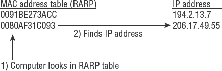
The system uses Reverse ARP (RARP) with a MAC address to find the corresponding IP address. Some systems can determine their own IP address by sending their own MAC address to a RARP server, as in the case of DHCP. For example, there are two kinds of telephone books: one is sorted by name order (like ARP), and the other is reverse sorted by street address. Figure 4.20 shows RARP using the MAC address to find the corresponding IP address. Later in this chapter, we discuss an additional method called Domain Name System (DNS) to assign human-friendly alphabetic names to IP addresses.
As you may you recall, the problem in layer 2 is that all the systems are transmitting so much that noise is created across the subnet. The issue is similar to noise in a school cafeteria. Some conversations are broadcast with everyone listening, while a few are discreet between a couple of users. With a layer 3 network address, it is possible to reduce traffic noise by unicast transmission to an individual address. Unicasting makes a point-to-point communication to only one device (a private call). So what if you need to send a message to more than one address, but not everyone? You could use multicasting to deliver the same data transmission to a group of addresses very efficiently. A multicast is similar to a conference call and is the basis of virtual networking and webcasts.
Network routing is the process of directing traffic to the intended destination. This can be accomplished by using static settings or by allowing the computer to follow instructions provided by a routing protocol. Routing protocols have been used for centuries to help ships navigate the globe, trains to switch tracks while heading to their destinations, and airplanes to safely navigate the clouds.
Static routing uses specific to-from mappings of IP addresses created by the network administrator. This is similar to following highway road signs. When driving to New York from Texas, for example, the driver gets on Interstate 20 and just follows the signs for turns and exits until they reach New York. The router's static mapping is quite similar. To-from settings are manually typed into the router and stored in the routing table of each router. The user's computer is set to use the router as their default gateway for every IP address located outside their subnet. Their default gateway is like an electronic on-ramp to the information superhighway. Each router on your journey points you to the next router (like a turn or exit ramp sign) until you reach your destination. Return traffic is routed back the same way. So both ends need to have their own set of directions to form a complete path for communications. These route settings will not change unless the network administrator manually changes them. Static routes are good for security and are used when the network traffic is both predictable and relatively simple. Figure 4.21 illustrates the analogy of the network routing protocol compared to a driver following highway road signs.

Larger or more-complex networks may have multiple paths to the same destination. The network might even have redundant connections for better fault tolerance. This could make static routing rather difficult to maintain. The routers get confused, just like people, if duplicate routes exist. Which route should we take? Routing tables contain a set of metrics such as cost, speed, and number of links to cross. The administrator can set these manually to help the computer use the best available route. An automatic split-horizon feature in the routing protocol blocks any loops that may occur by forcing travel in only one direction (path).
Dynamic routing uses a protocol algorithm to automatically adjust the path to the intended destination. This method uses special router information protocols to signal available paths (routes), dead routes (unroutable), and other changes. The routers will monitor routing updates and signal other routers to reconfigure their routing tables as changes occur. Dynamic routing is easy to enable. It removes the complexities of building an advanced configuration. To some individuals, this seems like the best answer; however, dynamic routing can be both beneficial and dangerous. Dynamic routing changes can be initiated by the following:
Router equipment failure
Addition of new networked devices
Incorrect configuration of a network-attached device, including a common workstation
Figure 4.22 shows how a false network route can be accidentally created through a user's PC. The user's computer software caused the problem by transmitting a route that should not exist.

By default, all network devices will listen to route updates. This can create a nightmare if left to default settings. Poor administration of computers and routers can cause traffic to be misdirected into a dead-end route or bandwidth bottleneck. Common examples of the dynamic routing protocols include the following:
Routing Information Protocol (RIP), which is a primitive method with few control safeguards. RIP is enabled on computers by default. RIP updates generated from a user's computer can inadvertently change the route path for everyone on the network (see Figure 4.22).
Open Shortest Path First (OSPF), which uses manually configured reference tables. OSPF is popular in larger networks.
Interior Gateway Protocol (IGP), which routes traffic within the same organization.
Border Gateway Protocol (BGP), which communicates between separate networks.
Proper design of the network usually includes implementing both static and dynamic routing. Static routes can provide a designated router of last resort if prior dynamic routes fail. Using a router of last resort is similar to saying, "Honey, I think we are lost; would you please pull over and ask this nice router for directions?"
For higher security, the routers should be configured to accept updates from only a trusted router—one the network administrator knows and indicates we can trust. The trusted router is authenticated by its MAC address, digital certificate, or access control list (ACL). Trust is established by forcing in depth testing using detailed challenges. Each test result provides a determination of the degree of trust. Trust is always temporary. Trust does not exist by a leap of faith, nor by legal contracts. Trust is measured per transaction. Constant unrelenting challenge-response continues trust until a single failure kills the trust. This helps prevent route corruption. Chapter 7 covers more details of security.
The Transport layer specifies the transport delivery method (see Figure 4.23). There are two basic methods:
Confirmed delivery uses a TCP connection to the destination. This is similar to requesting a return receipt and sending certified mail from the post office. TCP is slower and provides error correction.
Unconfirmed delivery operates on a User Datagram Protocol (UDP) connectionless datagram, which is typically broadcast across the network like a shout in a dark room. UDP is faster with less overhead. Even if transmissions are unicast between two stations, the higher-level software application would have to confirm delivery, because UDP does not offer delivery confirmation. There is no guarantee of the data being received on the other end. It is the responsibility of the recipient program to detect errors.
Next comes the session layer, where we get a login screen or other type of access.

The Session layer governs session control between applications (see Figure 4.24). This is where you initiate communications to a system and establish, maintain, and terminate a communication session. Examples include Network File System (NFS), SQL*net database sessions, and Remote Procedure Call (RPC).

Layer 5 functions of session and error control are handled in TCP/IP by the user's application software. Under TCP/IP, it is the responsibility of the user's application to manage the functions of session, presentation, and application.
The Presentation layer defines the presentation format (see Figure 4.25). This is where you specify the format and data structure to be used for programs. Layer 6 will specify the differences between a PDA, VT100 terminal, or workstation with What-You-See-Is-What-You-Get (WYSIWYG) display capabilities.
Layer 6 converts data received from the Session layer into an electronic format that can be handled by the upper-level Application layer (layer 7). It also works in the opposite direction, receiving application data from layer 7 and reformatting it for the underlying layer 5. For TCP/IP, the presentation function is combined into the TCP/IP Application layer.

The Application layer is where the problem-solving calculations of the computer software program run (see Figure 4.26). Various types of computer application software execute in the Application layer, including the following:
Systems Network Architecture (SNA) gateways, which convert the ASCII 7-bit data structure into an IBM Extended Binary Coded Decimal Interchange Code (EBCDIC) 8-bit data structure for the mainframe
Domain Name System (DNS), which is the program that associates a domain name to the matching IP address (for layer 3)
File, print, and web servers
Databases and office automation software (such as OpenOffice.org and Microsoft Office)
User's data encryption, such as Pretty Good Privacy (PGP) using variables (keys) to encrypt and decrypt the output. We explore encryption methods in Chapter 7.
It's best to remember that Layer 7 is the problem solver of work automation. User programs and workflow automation occur here. To help alleviate confusion, the common practice is to refer to the seven layers as the full protocol stack. A basic off-the-shelf router may have only parts of the OSI protocol stack to run just layers 1–3, which indicates that a layer 7 process such as a SNA gateway is beyond the devices' capability. Common network switches have only layer 1 and layer 2 stacks, while combination switch-routers have layers 1, 2, and 3 implemented. All-in-one network appliances may have the full protocol stack implementing all seven layers with different degrees of capability. Servers and workstations have all seven layers in use.
Note
It is important to remember that a gateway will run at the Application layer, which is the highest level of the OSI model.
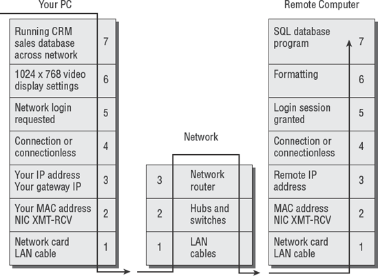
Now that we've covered all seven layers of the OSI model, let's take a finished look at the communication between two computers across the network using the OSI model. We will assume that a router is being used in the communication path.
First, the user makes a request in their application software on layer 7. That request is passed down through each layer on its way to the bottom. Along the way, each layer performs its function to ultimately transform the request into a series of electrical signals or light flashes for transmission on layer 1 (the physical layer of cable and voltages).
Next, the network hub (or network switch) on layer 1 passes the signal up to the layer 3 network router. The packet is routed through one or more routers directing the user's request to the intended destination computer. It helps to remember that network routing is similar to routing airline flights through particular cities, or railroad trains switching tracks as they travel across the country.
Finally, the request is received as a series of electrical signals (or light flashes) on layer 1 of the other computer. The request is passed up through each layer of the OSI model and processed accordingly. The request is then received in its Application layer, where it is executed. The response is packaged and sent back through the OSI model in reverse, until it reaches the application program on the other computer.
An example of how this looks is displayed in Figure 4.27.
Congratulations, you have now learned the secrets of the OSI model. You'll need to be sure to review its relationship with the TCP/IP model. The OSI model will be used as a discussion tool, while the TCP/IP model is the de facto standard of the real world.
Now we will move into discussing the physical side of networking. We will begin with a simple illustration of physical networks.
The first computer networks were created by connecting serial ports between two or more computers. This primitive design used modem software to handle file transfer between systems.
Networks evolved with the invention of token passing and broadcast transmissions. The invention of the hub, or shared media access unit, created the opportunity to connect multiple computers together on the same segment (again, referred to as a subnet). The concept of a network bridge was created to connect two subnets into the same, single subnet. A layer 2 bridge allows all traffic to pass from one side to the next. The bridge could be configured to allow broadcast across it or configured to filter broadcasts and reduce noise—it depended on the bridge manufacturer's design.
Later, it became apparent that it would be necessary to connect two separate networks together without merging them into a single subnet as a bridge would. Many people complained that too many systems were creating too much traffic when all the computers were located within one giant subnet.
Thus came the development of the router. Early routers were simply computers with two interface cards. Interface 1 serviced a connection to LAN 1, and interface 2 provided a connection to LAN 2. A software-routing program was then loaded to be run on the computer's CPU.
The routing program basically determines whether individual traffic requests need to cross to the other side. If so, the router passes the request through the other LAN interface to reach its destination. If the destination is within the same subnet (LAN 1 to LAN 1), the router ignores the traffic. This protects the other subnet from unnecessary data transmission noise (LAN 2). That is the basic function of a router. Routers forward data traffic when necessary and insulate users on other subnets.
Figure 4.28 shows what some of the networks would look like.

In modern networks, the routing function can be loaded onto a router card installed in the network switch chassis. Traditional routers are usually a dedicated device in their own chassis.
As networks grew, creating a standardized topology for all the connections became necessary. Early networks were very proprietary. It was difficult to mix equipment from different vendors. Although this was good for the manufacturer, it drove computer users nuts. Over the years, three basic network cable topologies have become widely accepted: bus, star, and ring. Let's look at the design of these three topologies.
One of the first topologies to become accepted was the bus topology (see Figure 4.29). This presented a relatively inexpensive method for connecting multiple computers.
In a bus topology, each computer is daisy-chained to the next computer. A single coaxial cable passes through the connector on the back of each computer on the network. This cable runs through the office like a single rope, which ties all the systems together.
The design has one major drawback: A break in the bus cable would interrupt transmission for all the computers attached to that cable. Cabling a bus topology can also be cumbersome.

The star topology is the most popular topology in use today (see Figure 4.30). In a star topology, each computer has a dedicated cable connection running to a network hub (or switch). This design offers the most flexibility for placement of workstations. It also offers the highest degree of cable redundancy. The cable redundancy ensures that other computers are not affected by a failure of another workstation's connection.
This is the design of most data networks. It is also used by the PBX telephone switch to connect individual telephone stations. The primary drawback to the star topology is the cost of all the additional cable required to make connections for each station.
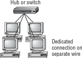
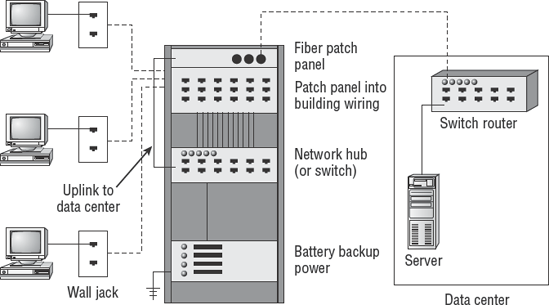
Figure 4.31 demonstrates the practical application of the star topology. Notice that each workstation has a connection to a nearby wiring closet. This design ensures that you do not exceed the maximum recommended cable length. The acceptable length of cable varies depending on the cabling type used. Normally it is 100 meters on unshielded twisted-pair (UTP). The star topology helps reduce the cabling cost by shortening the cable distance to reach each user. The hubs and switches are located in the wiring closet to connect users to the network.
Every cable is terminated at the wall plate near the user and at a patch panel in the wire closet. A patch cord connects the building cable from the patch panel to the ports of the hub/switch. A backbone connection is then run from the data center to the wiring closet to establish a complete path for network communication. Figure 4.31 shows the real-world implementation of a star topology, complete with wiring closet and backbone to the data center.
The most famous token-passing LAN protocol is IBM's ring topology, known as Token Ring (see Figure 4.32). Each LAN computer is connected to a media access unit (MAU). Each MAU is connected to both an upstream MAU and downstream MAU to form a backbone loop. Network traffic can be transmitted in either direction. This bidirectional loop is referred to as the ring.
A network ring topology has the advantage of built-in redundancy. If the ring breaks, all traffic will travel through the ring in the opposite direction, thereby avoiding the break point. The individual workstations are then connected into the ring by using a star topology.
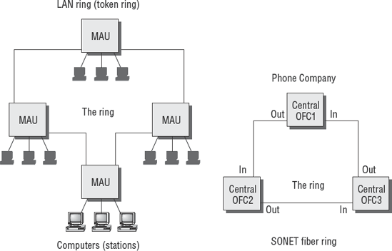
The telecommunications companies use the ring technology in their fiber-optic networks. This design allows the redundant path necessary to create a fault-tolerant network.
The important network links can have alternate path connections to increase redundancy. The meshing of star networks is a common method of providing redundancy similar to the approach used by a ring topology. The principal difference is that a meshed network is a series of point-to-point connections between critical backbone connections. The router determines which link to use based on predefined routing criteria. A network administrator defines the best link and the alternate path link to use if the best link is down.
There are essentially two types of meshed networks:
- Full mesh
A fully meshed network has alternate connections for every major backbone point on the network (see Figure 4.33). The primary obstacle to this design is the cost of implementation.
- Partial mesh
When you cannot afford a full mesh network, you may decide to implement a partial mesh for the most critical links (see Figure 4.34). Occasionally, the critical link may not be determined by the overall value of traffic. The additional link may be determined by the ability of the sponsor to pay the additional cost. A partial mesh is better than no redundancy at all.


IS auditors are fortunate to have the guidance of industry cable standards provided by the IEEE and the Electronic Industries Alliance/Telecommunications Industry Association building wiring committee (also known as EIA/TIA). Several methods have been developed to use a variety of cables to create a network. Each type of cable has its own unique characteristics of construction or transmission capability. Some cables are better suited for voice, for example. Others are designed for the high demands of data.
Note
You are not expected to design the cabling system used in a network. That is the job of a Registered Communications Distribution Designer (RCDD), a certified expert in the layout of cable systems. Industry reports verify that 97 percent of network problems are related to the cabling design, cable quality, cable implementation, or connector failure. Design services of an RCDD are usually affordable when justified against cumulative cost of downtime. IEEE and EIA/TIA standards specify more than 100 details for operating stability, safety, and building-code compliance. Details of proper design will far exceed the capability of a Microsoft Certified Systems Engineer (MCSE) or Unix administrator for all but the smallest of networks.
Cable installations are commonly referred to as cable plants. The cabling system for data and voice can be complex, depending on the requirement. A CISA is required to have a basic understanding of the three most common cables used to build a network. You should understand the description and limitations of each type.
Early networks used a form of coaxial (or coax) cable with mesh shielding to prevent electrical interference. The wire is similar to antenna cable or the cable for your television set. Coax has been replaced by unshielded twisted-pair (UTP) for most indoor environments. You can still use coaxial cable in areas prone to electrical interference or for outdoor connections. Figure 4.35 shows an illustration of coax cable.
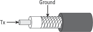
Coaxial cable is an older and slower design than UTP. It contains two electrical conductors (copper center, metal outer shielding covered with PVC plastic sheathing). It is commonly used for Ethernet networks with a bus topology. It's often used in distances up to 185 meters, but can be extended by using a repeater.
Unshielded twisted-pair (UTP) cable is the most popular for connecting computers to a network. Unshielded means that the wire does not have any protection from electrical interference. The twisting creates an electrical cancellation to prevent the wire from broadcasting like an antenna. Untwisted wire will create magnetic fields of interference that can swing a compass needle, whereas twisted wire will be invisible to the same compass.
UTP is an inexpensive, twisted, four-pair wire used for 10/100Mb Ethernet. Pairs are twisted to reduce electromagnetic interference (EMI). Each wire is run directly to a hub/switch in the wiring closet. Figure 4.36 illustrates the twisted wire pair construction.

Notice how each connector has two transmitting wires (send) and two receiving wires, which give UTP the ability to carry more data than coaxial cable. There are four common categories of UTP:
CAT-3 (Category 3) for voice only
CAT-5 (Category 5) for voice and data
CAT-5e (enhanced) for 1GB, 100Mhz data
Higher-rated CAT-6 and CAT-7 are also available for transmission up to 1,000Mhz.
Fire codes in commercial buildings specify that one type of jacket be used for twisted-pair cabling. The cheaper twisted-pair cabling uses PVC as the covering jacket. Unfortunately, PVC burns like a fuse when lit and produces toxic fumes. Fire codes call for plenum-grade Teflon jacketing to be used in plenum spaces to prevent the spread of fire.
A fiber-optic cable is constructed of tiny strands of glass fiber. Lasers or light-emitting diodes (LEDs) are used to flash signals through the glass strands. Fiber-optic cable is commonly used for backbone connections and long-haul installations. You can send multiple streams of data concurrently through the same strand of glass by using different color wavelengths. The process is called dense wave multiplexing. The drawbacks are price and the fragile glass strands, which break easily when stressed.
Fiber-optic cable has an extremely wide bandwidth. It can support concurrent transmission of voice, video, and data traffic by using multiple lasers to transmit light. Each laser color is a separate channel, allowing 12, 24, and 64 lasers to share one fiber without degradation. Higher end equipment can have even more lasers sharing the same stand of glass fiber. Speed, based on equipment used, is between 1 gigabit (Gb) and 100 terabits (Tb). Fiber-optic cable is also difficult to tap. Figure 4.37 shows the basic concept of a fiber optic cable multiplexing light into separate streams of traffic.
Note
It is important to understand when you would use copper twisted-pair and when you would use fiber-optic cable.

Now that you understand the OSI model and cabling, it is time to discuss the various devices necessary to build a network. Every CISA is expected to understand the purpose of common networking equipment.
Let's begin from the bottom up. The first thing you need is the customer requirements. What do they intend to connect to the network? The next question, what is their intended usage while on the network? We are constantly amazed at how many times the client expects a network to magically be all things to all people. Proper identification of requirements will go a long way toward aligning the network to the organizational objectives.
We can start with the number of user connections. Each user will need to plug into a network hub or switch. A network hub is an electrical connection box that amplifies and retimes the electrical signals for transmission. A hub is similar to an electrical junction box. All traffic is shared across each port.
A network switch performs the functions of a hub and contains an intelligent processor capable of running logic programs. Switches separate traffic between ports to create the appearance of a private communications line. This is the same design that is in PBX telephone switches and in LAN switches.
The network architect may encounter a problem with the distance between network devices. The solution may be to use a special cable type for that run, or to add another device to compensate for the distance. A network repeater can amplify the tiny electrical signals to drive longer distances. Repeaters receive a signal and then repeat the transmission down the next link. We could also use fiber-optic cable from that particular leg of the run. Fiber-optic cables are popular for use in long runs across the building or across the globe.
Maybe the issue is that wires are not acceptable for your intended usage. For example, it would be difficult to use a wire-line connection for counting inventory in a warehouse. The users would be unhappy, and the heavy steel wheels of the forklift would not be kind as they ran over the fragile cable.
Wi-Fi radio is good for communication over short distances. This will work in a warehouse. It will also work within a building for connecting handheld devices such as a PDA. Another wireless method includes infrared (IR) light, which requires line-of-sight access. This is good for limiting communication to the immediate area, but still needs security.
Tip
Wireless security is always a major issue. Chapter 7 covers this topic.
There may be a need to divide a network into small sections because of the sheer number of systems. Maybe you want to divide the network to put each group into their own subnet. Subnetting could protect the Accounting department from the Research and Development traffic, for example. This is performed by segmenting the big network into smaller groups of subnetworks (subnets).
You can subnet by using a router to provide access across the subnets while eliminating unnecessary traffic on each subnet. As you will recall, a router will insulate subnets from traffic conversations that do not involve their systems. Just connect the router to the switch/hub for each subnet and set up the router configuration.
You can also implement virtual subnets known as virtual LANs (VLANs) to divide the users. A VLAN is like an automatic conference calling list configured on the network switch (layer 2). A VLAN will simulate one subnet for all the target computers (that's where the term virtual comes into the name). The VLAN methods vary depending on the comprehension of the installer and the capability of the manufacturer. The basic methods of creating a VLAN are to use specific ports, to associate MAC addresses into a VLAN, or to create policy rules if the switch hardware has that capability. Let's discuss each of these methods here:
- Port-based VLAN (layer 1)
The administrator manually configures a specific port into a specific VLAN. Works well for uplinks, systems that don't move, and small networks.
- MAC-based VLAN (layer 2)
Ties the MAC address into a VLAN by reading the network traffic and then automatically reconfiguring the network port on your switch.
- Policy- or rule-based VLAN (layer 3 with layer 2 supporting)
A high-quality network switch reads the IP header in your traffic and executes an administrator's rule to join a VLAN based on protocol or by IP address. When correctly implemented, the process is automatic and does not require any software on the workstation. Switch ports will reconfigure automatically when the system is moved.
No matter what, every VLAN needs a router to access the other subnets. This router may be a physically separate device or a router CPU inside the same chassis. Now add the network servers and you will have a working computer network. Just be sure to include enough network-attached printers to make everyone happy.
Table 4.3 provides a summary of the various local area network devices that you will encounter.
Table 4.3. Local Area Network Equipment
Tip
To connect different networks, you need a router.
Routers provide intelligent decisions about routing traffic down particular links. The router is like a cop directing traffic in the direction it needs to travel. Routers come in a wide variety of shapes, sizes, and capabilities. An Internet router needs at least one Internet port and one LAN port. The type of router port depends on the type of circuit you need to connect.
Note
We will also need a firewall to protect our network. We discuss firewalls in depth in Chapter 7.
Several pages ago, we discussed the OSI model with examples of network services running on layer 7. In the example, we mentioned network servers with a few of the services they provide. Let's discuss two common network support services that relate to everyone using a network: DNS and DHCP.
Computers like to use hexadecimal numbers, network administrators like to use IP addresses, and all of us who run computers like to refer to machines by name. Names are so much easier to remember. Even names can get confusing, so the Internet is designed to allow fully qualified domain names. A fully qualified domain name (FQDN) is what you see on the left side in the URL portion of the browser as you surf the Internet. Have you ever wondered how the web browser finds the website you typed? The answer is by using the Domain Name System (DNS).
Routers have tables of IP addresses, along with the routes to take to reach those addresses. DNS servers are a layer 7 software application that contains a list of alias names and their associated IP addresses. DNS is how you end up reaching a website without knowing its IP address.
DNS offers additional flexibility. You can change the IP address without having to tell everyone about the address change. Just keep the DNS server updated with your new IP address. If DNS fails, you will not be able to access the target or you will resort to typing the IP address (if known).
Figure 4.38 shows the process of DNS looking at the company name and responding to your request.

A major problem with traditional DNS is the lack of security. Network productivity is essentially shut down if the DNS server is lost or attacked. Attackers can poison DNS by using fake servers or injecting fake DNS updates. This is the same problem discussed with layer 3 routing-table updates. The preferred method is to implement Secure DNS (S-DNS) by using ACLs and digital certificates. Name-lookup services and DNS updates would be accepted only from DNS servers able to continually verify their identity. Trust is destroyed upon the first failure in an ongoing challenge-response process.
For years, the job of a network administrator entailed the tedious task of configuring IP addresses on each computer. Manual settings are still the best choice for network servers; however, the user workstation is another matter.
Dynamic Host Configuration Protocol (DHCP) can automatically configure the IP address, subnet mask, and DNS settings on a computer. DHCP is an improved version of the original BOOTP using RARP. Both DHCP and BOOTP have the same operational design.
The theory of operation is simple. Figure 4.39 shows how DHCP works. Here are the steps:
A computer on your network is set up as the DHCP server. For remote dial-up, the better access servers will have this ability built in to support the modems. The DHCP server will be configured by your network administrator with a pool of IP addresses eligible for dynamic allocation.
The DHCP server listens on the network for an IP packet containing a type 67 code in the header. (Don't worry, that level of detail is not on your exam.)
A computer is booted on your network without an IP address. During the boot process, the computer recognizes that an IP is needed. The computer sends out a type 67 request asking for any DHCP server to assign it an IP address. The request contains the MAC address of the computer asking for an IP.
The requesting computer waits several seconds for a response.
Your DHCP server recognizes the type 67 request and responds with a type 68 reply addressed to the MAC address of the sender.
If the reply is received in time, the computer will accept the IP address and configuration settings. Then it will finish bootup and begin talking on the network.
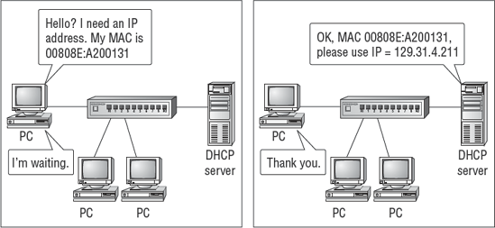
Every idea in the world has its Achilles heel. DHCP is no different. DHCP is implemented on OSI layer 2. This means that the DHCP mechanism is dependent on making a broadcast with its MAC address. Routers will not pass broadcasts because the resulting traffic is undesired on all other occasions. Remember, the router has two jobs: one is routing, and the second is providing insulation from unnecessary traffic. The DHCP server needs to be located on the same subnet to hear the computer making a DHCP request. Figure 4.40 shows how DHCP is blocked by the router.

Rather than building a bunch of DHCP servers, you can make a simple change to the router configuration. The router will still perform its normal functions; however, it can be set to forward DHCP requests to another subnet. The router command setting is called a bootup-helper-address or DHCP-helper-address.
This helper address setting will forward both the initial request and the associated DHCP server reply. The process is simple, as shown in Figure 4.41.
Warning
Dynamic IP addressing under DHCP is quite convenient for users. However, unsecured implementations of DHCP could grant an intruder easier access into the network. We discuss this security issue further in Chapter 7.

Modern routers can connect high-speed LANs to remote places for the purpose of creating a wide area network (WAN). Figure 4.42 shows what a WAN might look like.
Remote access is a popular feature. WANs are similar to a LAN; however, the implementation is different. Special equipment is necessary to adapt the transmission signal to telephone and radio equipment. Figure 4.42 shows the basics of expanding a network.
Setting up a WAN requires planning. Let's start with the most important component, which is information. The first thing you need is the customer requirements. What do they intend to connect to the network? Questions should be asked about who will be connecting to the network. Will the users be employees, business partners, or clients? Once again, you ask questions about their intended usage while on the network. What controls are planned? Hopefully, the client will be able to impress the auditor with answers that are well thought out.

Your client might want to have dial-in access to the network for their users. This can be accomplished in two ways:
- Individual modems
An individual modem can be connected to a computer on the network. This is a simple method that is adored by every hacker in the world. Individual modem connections bypass the majority of network security controls. Your monitoring tools may think this is just an ordinary internal computer with free rein over the attached subnet—or worse, the whole network. A hacker can easily find modems by using automated dialing tools or checking a list of known modems posted at hacker sites. Insecure modems are still a threat to security. A sharp auditor will investigate the compliance of dial-in modems to their security policy.
- Network access server
An access server can be used with a modem pool. It can be a slick product from Cisco or a PC configured with special software such as Microsoft Remote Access Service (RAS). The access server should have special monitoring and security controls.
It is safe to assume that the remote connection will be attached to one of the routers. You should encourage the practice of separating remote connections into their own subnet. This promotes separation of duties with the benefit of simplifying the implementation of security controls. Remote router connections will probably need a firewall if the connection is wireless or could involve someone besides the organization's employees.
High-speed telephone circuits such as T1 (1.54Mbps) and T3 (44.5Mbps) use a channel service unit (CSU) instead of a regular modem. The CSU is a special device used by the telephone company and designed for connection to their equipment. Telephone circuits like this can be divided or combined by using a multiplexor. A multiplexor converts one high-speed telephone port into many lower-speed ports, or combines several lower-speed lines to appear as one high-speed line. Multiplexors are invisible to the user.
Table 4.4 summarizes the various types of equipment you might use when connecting to a WAN.
Table 4.4. Networking Equipment
Device | Purpose |
|---|---|
Router with WAN port | Connect LAN to remote WAN via telephone circuits. |
Modem | Low-speed telephone dial-up connection to the access server for users, or attached to the router for remote administration. |
Channel service unit (CSU) | Similar to a very special modem. Designed to connect a router port to a high-speed telephone company circuit. Fast transmission speeds from 1MB to 44MB per line. Common in WANs. |
Multiplexor | Combines multiple lower-speed telephone circuits to appear as a single fast circuit, or splits a fast circuit into multiple lower-speed connections. It has a function similar to that of any splitter or combiner. |
The telephone company will provide whatever service the client is able to afford. In some areas, the services may be limited. High-speed services such as Digital Subscriber Line (DSL) are available in only limited areas. The limitation is based on cost: Your telephone company will invest in areas that have enough demand to warrant the business cost. In rural areas, people have few choices. These are known as last-mile service areas, where the phone company will lose money.
The world of telephone circuits is based on several generations of telephone company equipment. The older generation is based on the Integrated Services Digital Network (ISDN). The newest generation is built by using Dense Wave Multiplexing (DWM) with multiple lasers over fiber optics with Asynchronous Transfer Mode (ATM). Each generation of technology has intrinsic advantages and disadvantages. Let's run down the list. We suggest you pay attention because these details may be of value.
The following are various ways you can connect to your network via a wired route.
Dedicated telephone circuits are billed by location with actual usage billed by distance. The user is charged a monthly fee plus any long-distance charges.
- Plain old telephone service (POTS)
POTS is available almost everywhere. This is the regular telephone line capable of data transmission up to 56Kbs. POTS is based on using half of an ISDN circuit. POTS is the only circuit that is considered to be "off" when not in use. Transmission is halted when you hang up the phone. All the other telephone circuits we discuss are always live and transmitting.
- Integrated Services Digital Network (ISDN)
ISDN is the foundation of POTS. Therefore, you should be able to get ISDN almost anywhere. The basic rate interface (BRI) bandwidth starts at 128K per line. It can be used as one 128 K/bps channel or divided into two 56 K/bps circuits. Optional ISDN speeds on a primary rate interface (PRI) can go up to 1.544 Mbps. You can run up to 23 channels of data, voice, and video over ISDN. In Europe and Australia, the PRI speeds are 2.048 Mbps, equal to 30 channels. Most video conference sets use ISDN. The ISDN circuit is always on and live.
- Primary trunk line (T1)
T1 is a dedicated trunk line equal to 28 POTS circuits. The user is charged by the mile for basic T1 service. Telephone PBX systems are usually connected by one or more T1 trunks running back to the telephone company's central office. The administrator can provision (divide) the trunk into whatever variety of factional service they desire for voice, video, or data. T1 lines never shut down. In North America, T1 speeds are 1.544Mbps each, and 2.048Mbps in Europe.
- Digital Subscriber Line (DSL)
DSL is usually the least-expensive high-speed circuit using a higher frequency over a standard telephone line. This allows your standard voice telephone line to simultaneously carry DSL higher-speed traffic without conflict. DSL is substantially limited by distance. It is available only in high-density areas where the phone company can make a profit. Speeds range from 368Kpbs to 1.544Mbps. The DSL circuit is always on and live. If you turn off DSL equipment, the phone company disables your circuit.
Each of the circuits listed above represent a dedicated connection which is either: 1) between the telephone company and the buyer's office, or 2) installed as a private line between the buyer's offices. Figure 4.43 shows the relationship of the different telephone circuits.

Packet switching evolved to eliminate the need for everyone to set up expensive dedicated lines. The Internet is a packet-switched network. Transmissions can route anywhere without regard to distance. This means that the path from Los Angeles, California, to Mexico City, Mexico, might pass through Atlanta, Georgia, depending on the carrier and the time of day. Similarly, using a special diagnostic tool, we noticed our downloads from Dell were routed from Grapevine, Texas (near Dallas), to Parsippany, New Jersey, and then to Austin, Texas (a journey of more than 2,700 miles). Interesting, because our Grapevine office is only 229 miles from Dell in Austin, Texas. In packet switching, the source and destination are known, but the path automatically changes (it is variable).
- International telecommunication standard X.25 (X.25)
X.25 was an early 1970s digital packet-switching protocol designed to create WANs over public data networks run by the telephone company. It's considered the foundation of modern switched networks. X.25 contained three major advances:
A field for handling special transmission parameters called the facility code. This allowed you to specify a quality of service.
Ability to create permanent virtual circuits (PVCs). This administrative configuration setting allowed the administrator to specify a fixed path for all communication. PVCs were created to replace the leasing of dedicated telephone lines.
Ability to create switched virtual circuits (SVCs). The source and destination were specified, but the path was temporary, dynamic, and constantly changing. SVCs were not dedicated.
X.25 is now used primarily as a reference model, except for a few old die-hard customers. The lessons learned in X.25 created new technology for communications.
- Frame relay
Frame relay (FR) is an inexpensive packet-switching system using the same type of interface protocol as X.25 with PVC and SVC capability. Frame relay is different from X.25 in format and functionality. The FR data packets may arrive out of sequence. Therefore, it is important to have equipment capable of caching enough data in memory for reassembly sequencing before use by the user. Frame relay works great for data/voice applications, but some video transmissions may appear choppy to the viewer unless adequate memory caching is used. End connection points are specified by using data link connection identifiers (DLCI numbers). The DLCI specifies the destination, similar to a phone number. Frame-relay speeds range from less than 1.544Mbps up to 44.5Mbps. The frame-relay circuits are always on and live unless you want the telephone company to disable your circuit for several days.
- Asynchronous Transfer Mode (ATM)
ATM is the new backbone of the telecommunications industry. The transmission speeds are very high, from 155Mbps to more than 1GBps. That is more bandwidth than most companies could ever use in this decade. The ATM design implements cell switching and multiplexing to ensure solid delivery. Data is sent down multiple concurrent paths to the same destination. The first data cell to arrive will be used, while later duplicates will be discarded. ATM can use 132 switched paths (SVCs) during transmission. It is very reliable. The ATM circuit is always on and live unless you want the telephone company to shut down your circuit for several days.
- Switched Multimegabit Data Services (SMDS)
This is a very high-speed data communications service. I doubt it would ever be mentioned on your exam. It's included to demonstrate where public data networks are going. The first ATM services offered speeds of only 1.5Mbps, and SMDS was 3.4Mbps. Advances in technology raised the speeds 100 times. SMDS is available on a limited basis at 340Mbps to 3.4Gbps (3,400Mbps). It's designed for transmitting over a dual bus in metropolitan networks. The SMDS payload is big enough to encapsulate (carry) entire LAN traffic (Ethernet 802.3, 802.4, and Token Ring/FDDI 802.5).
SMDS has two interesting features: security and group addressing. Source addresses are verified by the network to ensure that the assigned interface is legitimate. The user is protected from address spoofing (fraudulent devices). Source and destination addresses can be screened to prevent delivery of unwanted traffic. Group addressing allows multicasting of a single transmission to a specific group of addresses without sending to anyone else. The private virtual network features add additional security and efficiency.
Warning
We have discussed several communication circuits that are always on and live. This can allow a hacker to attack you 24 hours a day, every day. High-speed circuits can support high-speed attacks or high-speed theft of your data. Think firewalls!
The basic network concepts are identical for developing a network solution sans wire. Wireless is used when the wiring costs are prohibitive or the wires would defeat the intended purpose.
Each wireless system requires a minimum of two antenna systems. The antenna stations have both transmitting and receiving capabilities.
The following are various ways you can connect to your network via wireless access:
- Wi-Fi radio
This is the most common type of wireless access. The design uses a layer 1 transmitter/receiver to support a signal range of up to 1,500 feet. It uses digital spread spectrum or frequency hopping over a private radio channel. It is commonly used by the military and private companies operating mobile fleets. Large-scale Wi-Fi may use cellular service. Smaller-scale use includes Wi-Fi hot spots.
It's relatively simple to construct a wireless LAN. Several vendors offer low-cost wireless access points (APs), which are similar to a wireless hub or router. The AP is connected to a wired network and broadcasts connectivity to handheld devices. Usually the range of an AP is 300 feet, equivalent to 100 meters. Users can move freely within the 300-foot broadcast range without losing any connectivity. The individual broadcast area (range) is also known as a cell. This is comparable to the design of cellular telephone networks. The effective range can be increased by combining APs and their multiple cells (service range). Wireless LANs (WLANs) are based on the IEEE 802.11 standard.
- Station (STA)
The station, or Independent Basic Service Set (IBSS), is a wireless device on the end of the network, such as PDA, laptop, or mobile phone.
- Access point (AP)
This is a wireless transmitter/receiver that provides basic network services, usually within 300 feet, equivalent to 100 meters. Higher-power transmitters with longer ranges are entering the marketplace. The AP and STA compose a basic WLAN.
- Cell
The individual AP broadcast range is known as the cell, or span of coverage. Multiple AP cells are linked together to increase the range and allow roaming within the building or between buildings. The relationship is shown in Figure 4.44.
A group of wireless devices uses an ad hoc arrangement when communicating directly with each other in a peer-to-peer relationship without an AP. The terminology ad hoc is based on the dynamic master-slave relationship between devices. Ad hoc networks have a short broadcast range, which is also referred to as the piconet, or personal area network (PAN). Bluetooth is the most common ad hoc network for providing connectivity between a cell phone and a wireless headset.

Pico means one trillionth or very small. Bluetooth technology creates an ad hoc network of one master and one to seven slaves, up to a total of eight devices. This teeny network provides short-range direct-link interconnectivity.
Warning
The lack of effective security is an enormous drawback in wireless networking. IEEE's original design of Wired Equivalent Privacy (WEP) proved to be practically worthless. As of 2005, wireless networks using 802.11a, 802.11b, 802.11g, and 802.11n have been officially deemed unsafe. Those unsafe implementations represent the majority of wireless LAN equipment installed worldwide. In response, IEEE issued a revised wireless standard in 2005 called 802.11i Robust Security Networks (RSNs). A third-party security VPN must be used when RSN is not available. We discuss RSN in Chapter 7.
- Satellite radio
This is the next most common method. The signal is bounced off a low-orbit satellite in space. Obviously, the service area is huge. Very popular for remote communications or linking to numerous field locations, satellite is heavily used in trucking fleets, ships, and retail chain operations. The transmission speeds are lower, and cost is an issue unless you buy a large volume of air time. Private uplinks are available for telephone, data, fax, and video applications. Satellite data-phones are common for emergency response. Transmission speeds are 9.6bps to 4MBps, with specialized hardware required. Satellite communication has a 2- to 5-second transmission delay due to signal propagation delay. For example, the Iridium satellites are less than 500 miles up compared to 23,000 miles for geosynchronous satellites.
- Microwave
Microwaves are used in short-distance runs—1 to 30 miles— across cities and over mountain ranges. Microwave service has been around for 50 years. The only drawbacks are the clear line of sight required for transmission and the construction cost. Connection speeds range from 1MBps to 100MBps. The primary advantage is no recurring transmission costs aside from equipment purchase and regular maintenance. Severe weather and fog can disrupt signals.
- Laser
Lasers are being used as an alternative to microwaves. Lasers also work to connect two offices by using the unobstructed aerial space to cross above public roads. It is similar to fiber optics without the fiber cable. Transmission speeds from are from 1MBps to 100MBps. Severe weather and fog can disrupt signals.
Warning
It is strongly recommended that every land-based wireless connection have a firewall installed between the wired network and the wireless equipment. Many implementations of wireless encryption still contain holes in security. Motivated hackers can access radio connections by using technology available in the amateur radio community. Laser access may be more difficult, but hackers have proven it is possible.
It is important that we address the subject of short-range wireless networking for use with radio frequency identification tags. This is an area that will increase as more organizations attempt to implement automated tracking.
Radio frequency identification (RFID) is a hot topic. RFID uses a tiny tag, which contains silicon chips and antennas that enable the tag to be detected by scanners. The original purpose was to protect inventory from department store shoplifters. Later RFID was expanded to include planting tags in boxes for better warehouse control.
The security and privacy issues regarding RFID are increasing every day. As an IS auditor, you are expected to have a basic understanding of RFID. You will encounter an increasing number of issues regarding RFID implementations. Citizens are growing more concerned about their privacy.
Passive RFID tags are regularly used in inventory control and for implant in live animals. These tags may be covertly read at a distance. Newer tags are built into the product and are not detectable. The user could be scanned as they walk through a building. RFID tags in adult products or medical prescription packages could lead to interesting conversations about privacy.
Under President Bill Clinton's administration, the U.S. Food and Drug Administration and other government agencies have approved the use of RFID tags for human implant. There are multiple human implant vendors on the market today. The ads for human implant claim RFID tags are safe and nonremovable. One vendor claims that the intended purpose is to protect newborn infants by tracking your baby in the hospital. Other advertised uses include prisoner identification or the identification of elderly individuals unable to provide information for themselves. This new RFID situation poses an increasing variety of privacy concerns.
Another type of RFID uses a transponder to transmit a signal. The RFID transponder uses an internal power source to respond to queries by an antenna in the area. A common example is the toll tag used by a toll road authority for the electronic collection of usage fees. A variety of organizations including law enforcement collect surveillance data on common citizens by using active RFID toll tags along with automobile satellite services and cell phone records.
Government researchers have determined RFID tags can be easily cloned without the user's or recipient's knowledge. Any RFID signal you can read can be duplicated. The implications may be either good or evil depending on the desire of individuals. You can expect more controversy as the issues develop.
The IT management may choose to maintain a network administration staff at each site or use remote access. Either choice has its advantages and disadvantages.
Routers can use a modem for individual low-speed telephone connections of 56K. This would be intended for remote support of the router itself. (Turn off the modem when not in use to keep out the hackers.)
We have discussed both LAN and WAN networks. The discussion would not be complete without mentioning the multitude of variations. In the beginning, the LAN was the focus. Then the need arose to connect to remote users. Supporting remote connections became rather involved, and the whole idea was termed a WAN. Since that time, the world has continued to generate new products with a combination of need, politics, and marketing. The LAN-WAN naming convention has brought us new terminology for other types of area networks, including personal area networks (PANs), campus area networks (CANs), metropolitan area networks (MANs), and storage area networks (SANs).
Table 4.5 introduces you to the types of area networks that the CISA is expected to encounter. You need to know the descriptive features of each one.
Table 4.5. Common Networking Acronyms
Network Acronyms | |
|---|---|
Local area network (LAN) | Connecting computers within the building by using hubs, switches, and routers. Usually very fast connection speed of 100/1,000MB. |
Virtual local area network (VLAN) | Artificial grouping of disparate workstation ports across various LAN switches to appear as if all were connected to a common subnet. Similar to a PBX conference-calling group. Primitive VLANs use fixed ports. Advanced VLANs use dynamic rules to automatically assign ports without user/administrator intervention. The user can plug in anywhere, and the switch reconfigures the port within fractions of a second. Moves are automatic using IP address rule, protocol rule, or MAC address rule. |
Storage area network (SAN) | A cluster solution for interconnecting different kinds of file storage for server farms. Often use Ethernet, SCSI, ATM, or fiber-optic connections. |
Personal area network (PAN) | Coverage is within 10 feet of the immediate area. Used for connecting PDA and handheld personal devices to synchronize with your computer. Also known as a Piconet. |
Campus area network (CAN) | Connecting computers between buildings in a school or corporate campus by using cable, fiber optics, or wireless transmitters. |
Metropolitan area network (MAN) | Connecting computers between different buildings located in the same city. |
Wide area network (WAN) | Multi-city connection over longer distances. Connection speeds range from under 1MB on cheap telephone circuits to over 1GB on optical carrier circuits (OCx). |
Tip
Political battles over authority will exist regarding the control over most networks. The basic operation of local and wide area networks is quite similar. The principal difference is the area of coverage and who is in charge of that area.
Networks are constantly increasing in complexity. A network outage can cause significant impact to an organization's business activities. It would be naive to assume that the systems could run without supervision. The network administrator holds the duty of monitoring network performance and is the first line of defense for detecting security violations. This is possible only with specialized tools designed to manage network assets. Let's take a look at the basic tools used to manage the network.
Today almost all computers and network devices have the capability for centralized system logging, known as Syslog. The design sends audit log messages to a centralized server for aggregation of event logs and alerts. Syslog is a common and simple utility that requires little processing power.
It is an excellent tool to aid the monitoring efforts of system administrators. This form of centralized logging is excellent for security monitoring and audit log retention. Syslog can be enabled on an individual system within a few minutes.
Syslog has some disadvantages. Unfortunately, it does not contain message authentication. There is still no mechanism for providing message integrity. The Syslog design also lacks the mechanism to verify delivery of a message.
The principal advantage of Syslog is that audit logs can be automatically transmitted to another server for safe storage. This assists in providing evidence for the auditor. It can also be a compensating control in environments where the logs may be deleted.
Cable industry studies report that 97 percent of all network problems are related to faults in the physical cable plant (layer 1). Advanced handheld cable testers are used to certify the quality of network wire runs. These handheld scanners test individual data cables by automatically running a series of electrical tests and transmission tests. The tests check a variety of conditions, including compliance to recommended length, signal strength, transmission cross talk, electrical noise interference, and electrical pin connections. Cables that pass these tests are certified as compliant. Once certified, the cable is ready for production use.
A computer can be configured with special software designed to record and analyze network transmissions. This software is often referred to as a packet sniffer. Network administrators use this as a tool for troubleshooting network performance problems. The sniffer operates in promiscuous mode and records transmissions of every packet transversing the segment. The sniffer can see only traffic within the segment to which it is attached. It cannot see traffic across the routers or switches unless the traffic is passing down the segment where the computer is attached. The sniffer will show you communication between systems and the passwords used.
Hackers can use a sniffer to capture user IDs, passwords in clear text, and map the network. This is why sniffers are considered a tremendous threat in the wrong hands.
Networks can be monitored and controlled by using the Simple Network Management Protocol (SNMP). The network administrator usually runs an SNMP network management program such as HP OpenView to monitor servers and routers. A Network Management System (NMS) gives you the capability to check the up/down status of individual network devices.
You can use SNMP to monitor almost any network device, including servers, routers, gateways, hubs, and workstations. By default, SNMP provides the capability to do the following:
Read: Monitor a device with notification of possible error conditions
Write: Reconfigure limited system parameters
Use SNMP to reboot or shut down the network device
The SNMP security mechanism is extremely weak and relies on simple passwords transmitted in clear text that are easy to read. As an auditor, you should be concerned about SNMP being allowed to travel unregulated across the network. All SNMP-managed devices need to use unique passwords rather than the default passwords public and private.
Vendor documentation will refer to the passwords of public and private by using the term community strings. A community string is actually a simple password used to gain control of the target system. All that is needed is the target system IP address and matching SNMP password (community string). Many organizations are not properly educated about the public and private password risk. It is the network administrator's job to define SNMP access control lists and to manage the implementation of unique SNMP passwords for each device. Failure to do so would grant anyone control of any system using the same SNMP password (community string). Otherwise, SNMP is a good internal monitoring tool.
The Remote Monitoring Protocol version 2 (RMON2) is a major improvement over version 1, offering data beyond basic network health via up/down status. RMON2 gives you the ability to monitor all seven layers of the OSI model, including application performance. You can view the performance of a single application running across the network or select a stratified view of the combined bandwidth allocation.
Twenty-one layers of RMON performance data are available. By comparison, a network packet sniffer can record only a snapshot containing a few minutes or hours of layer 1, 2, and 3 data. RMON2 can provide a broader range of nonstop performance while recording tremendous levels of detail covering a time span of hours, days, months, and even years. Most RMON2 implementations write the records to an SQL database for reporting and long-term retention. This is a true enterprise-class monitoring system.
Note
It is important to remember that useful administration tools also make good hacker tools. Every administrative tool needs to be governed by the organization's internal controls.
The information systems auditor is expected to understand common networking technology. You should know the name of each piece of equipment and its role in the computer network. Occasionally, you may encounter systems that are filling an all-in-one role. In that event, you should remember computer architecture limitations: It is not possible for single-processor systems to perform all functions without a momentary interruption of the security software. Both single-user systems and multiuser systems have design vulnerabilities that can be exploited.
It is the job of the CISA to evaluate the auditee's technology implementation. Despite advancements in technology, common problems will usually be rooted in fundamental errors of design or implementation. Security is best implemented in multiple layers to provide compensating control for design vulnerabilities. The purpose of this chapter has been to familiarize you with the basic concepts. The world depends on the CISA to review the client's design for the purpose of identifying vulnerabilities or failure points. You should always ask yourself whether the technology truly fulfills the objectives of the business and the objectives of security controls. If not, it might just be a superfluous investment in way-cool technical junk. Technology without proper internal controls is a bomb waiting to explode.
- Understand the basics of computer architecture.
Computer architecture comprises a central processor unit with high-speed cache memory and solid-state RAM memory. All the computer's components communicate by using a shared data bus, constructed of electrical wires. Interfaces connect the data bus to the electronic components such as the video display or the hard disk drive. There are different classes of computers based on size and capability, including the personal computer, midrange computer (mini), mainframe, and supercomputer.
- Remember that computers may use single CPUs or multiple CPUs.
In either case, the system can be running in time-sharing mode to support multiple users (multiuser mode). With multiple CPUs, it is possible to assign each processor to a particular task. Multiple-CPU architecture provides a way for security software to run completely uninterrupted. Otherwise, the computer security software will be interrupted in the normal course of servicing processing requests.
- Know that the computer operating system manages communications between the hardware and user programs.
The operating system provides services for scheduling, dispatching, security, and input and output functions. All operating systems are not equal in their implementation of internal controls. The mainframe represents a role model for the highest level of system controls. Security controls are lacking while the system is in supervisory state during maintenance or initial program load (IPL).
- Understand that system ports must be protected from physical access and logical access.
Examples of system ports include interface ports, the console or master terminal, and all network communication ports.
- Know that computer networking is accomplished by using a variety of devices.
Network cables are joined together by hubs or network switches to form a network. Smaller networks are known as subnets. Multiple subnets can be joined together by using a router. The purpose of the router is to direct traffic between different networks. A firewall is a specially configured device that selectively routes traffic between two networks. The firewall's method depends on its internal architecture. A proxy firewall prevents direct access into the network. Traffic still goes through the holes in the firewall, but the proxies relay the request on behalf of the user.
- Remember that wide area networks are created by using wired telephone circuits or wireless transmitters to connect LANs.
Network security at external access points is always a concern. Every network access point presents an opportunity to motivated hackers. High-speed communications circuits allow for high-speed attacks. Modern telephone circuits, except for POTS, are always on and present a 24-hour attack opportunity. The first wide area networks were created by using circuit-switched telephone lines that were billed by distance traveled. Newer packet-switching technology charges for the data sent, not the distance traveled.
- Understand that the OSI model provides a simple reference for explaining the functions occurring in computer networking.
Nobody actually runs the OSI protocol; in the real world, most communication is performed over the Internet Protocol (IP). A CISA must demonstrate an understanding of how OSI relates to IP.
- Remember that computer networks can be complex and require constant monitoring.
Typical monitoring tools include the packet sniffer to analyze communications, Syslog to transmit system logs to a safe location for review, and Simple Network Management Protocol (SNMP) to alert administrators about conditions impacting network operations. SNMP can feed a network management system, such as HP OpenView or Remote Monitoring Protocol (RMON2).
Which RAID level does not improve fault tolerance?
RAID level 0
RAID level 1
RAID level 2
RAID level 5
Which type of network device directs packets through the Internet?
Hubs
Routers
Repeaters
Modems
This type of data transmission is often used to transmit video signals across the network.
Unicasting
Broadcasting
Multicasting
Pinging
This address is manufactured or burned into network equipment and is totally unique.
Domain name
IP
Media Access Control
Street address
This network is often used to provide vendors and customers limited access to corporate network services.
Internet
Extranet
Intranet
Access net
Which of the following is a list of OSI model levels from the top down?
Application, Physical, Session, Transport, Network, Data-Link, Presentation
Presentation, Data-Link, Network, Transport, Session, Physical, Application
Application, Presentation, Session, Transport, Network, Data-Link, Physical
Presentation, Data-Link, Network, Transport, Session, Physical, Application
Which of the following is the most popular media for connecting workstations in a corporate environment?
Coaxial
Shielded twisted-pair
Unshielded twisted-pair
Fiber optics
This protocol is layer 3 routable and is the backbone of the Internet.
IP
OSI
TCP
NetBIOS
What type of network firewall is often the simplest to implement but has the worst logging capabilities?
Proxy
Application
Packet-filtering
Adaptive
What does the third layer of the OSI model equate to in the TCP/IP model?
Network
Data-Link
Transport
Internet
At which layer of the OSI model does a gateway operate?
Layer 3
Layer 5
Layer 6
Layer 7
Which of the following network topologies provides a redundant path for communication?
Fiber-optic
Star
Ring
Bus
What is the purpose of the Address Resolution Protocol (ARP)?
Find the IP address
Find the mailing address
Find the MAC address
Find the domain name
What is the security issue regarding packet analyzers?
Viewing passwords
Special training
Purchase cost
Only for auditor's use
Which of the following is an implementation of the demilitarized zone concept?
Dedicated processor and a multiprocessor system
Screened subnet
Bastion host on the network
Dedicated subnet for internal users
Which of the following protocols is likely to be used for monitoring the health of the network?
OSI
SNMP
SMTP
RIP
What does the designation of N-1 best represent?
Need for additional equipment
Number of routers
Meshed network
Number of links
What is the difference between a router and a switch?
Both operate at layer 2; the router routes traffic, and the switch connects various users to the network.
Both operate at layer 3; the router routes traffic, and the switch connects various users to the network.
They operate at OSI layer 3 and layer 2, respectively.
They operate at OSI layer 2 and layer 3, respectively.
Which type of network cabling is relatively immune to interference, difficult to tap, and can run extended distances?
Coaxial
Shielded twisted-pair
Unshielded twisted-pair
Fiber-optic
Which type of memory is used to permanently record programs on solid-state chips and retains the data even after power is turned off?
Random access memory
Read-only memory
Flash memory
Optical memory
What is the auditor's interest concerning SNMP community information?
Community strings are actually passwords, and the private password can write changes to the device configuration or force a reboot.
Network-attached devices should be configured into individual communities for separation of duties.
Security is nonexistent in the first two versions of the SNMP protocol3
Operations staff should use SNMP to monitor the network and to provide early notification of problems or of information indicating that incident response is needed.
The ________ network topology provides a redundant path to transmit data.
Bus
Star
Chain
Ring
Which of the following statements is false concerning the communication circuits used in wide area networking?
Switched virtual circuits (SVCs) may use different routes to reach the destination.
Digital circuit-switched lines are dedicated between locations.
Packet-switched circuits are charged according to distance.
Circuit-switched lines allow the user to transmit any amount of data.
The architecture of a computer with a single central processing unit (CPU) contains which of the following points that represents the biggest area of interest to the auditor?
Time-sharing is used to service the different processing tasks one at a time.
An upgrade to a multiprocessor system should be justified to improve response times.
System control software is halted between processing tasks.
A pipeline design should be implemented to minimize system idle time.
Which of the following RAID implementations is designed for the disk array to be configured into one large virtual disk partition using high-speed asynchronous data transfer?
RAID-1
RAID-7
RAID-5
RAID-6
Even with advanced security software running on the network, which of the following OSI layers represents the vulnerability to subversion created by hardware port access?
OSI layer 1
OSI layer 2
OSI layer 3
OSI layer 7
In network communications, the ________ transmission sends a single data packet to multiple addresses for applications such as Internet-based television.
Broadcast
Multicast
Visicast
Unicast
Which of the following network protocols uses the MAC address to find a computer's IP address?
Domain Name System (DNS) protocol
Reverse Domain Name System (RDNS) protocol
Reverse Address Resolution Protocol (RARP)
Address Resolution Protocol (ARP)
The Internet Protocol (IP) contains a special feature for separating different types of communication between network addresses. What is this feature called?
Software port
Hardware port
Dynamic Host Configuration Protocol
Virtual Communication Protocol
Default settings are used by vendors to help users get the system up and running. What is the auditor's primary area of interest regarding default settings?
Saves time and money for the user
Represents the manufacturer's recommended settings
Well-known settings published by the vendor
Reduces support headaches, which increases operational uptime
At which OSI layer does software encryption and decryption occur?
OSI layer 7
OSI layer 6
OSI layer 5
OSI layer 4
The ________ can be poisoned by a hacker to prevent the computer from converting computer names into network addresses.
Address Resolution Protocol (ARP)
Reverse Address Resolution Protocol (RARP)
Border Gateway Protocol (BGP)
Domain Name System (DNS)
Which of the following best describes ad hoc networks?
Dynamic connection of remote devices
Fixed connection of devices
Active Device HOst Communication
Wireless connection using a static configuration
Except for the older plain old telephone service (POTS) lines, what is the primary issue of remote access over telephone company circuits?
The cost of service may be expensive.
The available bandwidth may be too slow.
A remote-access circuit is always active to accept communication.
Remote access servers (RASs) may be used to create a dial-up modem pool.
Why are firewalls used with OSI layer 7 (Application layer) proxies?
Firewalls operate at the network layer by using filters based on to-from addressing.
Proxies perform the request on the user's behalf without granting direct access.
Firewalls close communication ports to prevent access.
Proxies grant direct Internet access without the need of a firewall.
A. RAID level 0 improves performance and can provide large logical drives but it does not increase redundancy. It is often used in combination with other levels to improve performance and redundancy. The purpose of RAID-0 is to combine multiple disks into one giant virtual disk.
B. The function of network routers is to route IP packets throughout the network or the Internet. The router does not know the entire route to the destination. The router holds a routing table that simply provides the address of the next point down the path to the destination. Network routing is like a game of connect-the-dots. The data must travel sequentially from one router to the next router until it reaches the intended destination.
C. Multicasting is used to transmit packets to multiple systems simultaneously but does not transmit to all systems. It is often used to transmit video across the network. Broadcasting is used when transmitting to all systems. Unicasting is transmitting packets to a single-destination system only.
C. The 48-bit MAC address is manufactured into network equipment. Often, it is possible to override by using configuration tools. In a local area network, a 32-bit IP address is used for routing.
B. An extranet allows certain people limited access to corporate network services. An intranet is an internal corporate network. Access net is made up.
C. It helps to remember the memory tool Please Do Not Throw Sausage Pizza Away.
C. The most popular media is UTP, or unshielded twisted-pair. STP, or shielded twisted-pair, is more resistant to electronic noise and may be used in a shop environment. Coaxial cable is no longer used for connecting workstations. Fiber-optic cable is often used for interconnecting servers.
A. Internet Protocol (IP) is the major routable protocol. Transmission Control Protocol (TCP) is used on top of IP to provide reliable sessions. User Datagram Protocol (UDP) is connectionless without delivery confirmation. NetBIOS is not a routable protocol. The OSI model is used to explain network communications.
C. A router can be configured as a simple packet-filtering firewall by using an access control list. Packets are filtered based on the source address, destination address, and type of service. The problem is that packet filters have poor logging and the filter rules may be too broad to be effective. Packet filters do not support complex rules using
if-thenstatements.D. The third layer of the OSI model is the Network layer. Use the memory tool of Nor Do I Throw Apples to remember the layers of the TCP/IP model. The third layer of the TCP/IP model is the Internet layer.
D. According to ISACA, the gateway operates at application layer 7 in the OSI model. The function of the gateway is to convert data contained in one protocol into data used by a different protocol. An example is an SNA PC-to-mainframe gateway converting ASCII to mainframe Extended Binary Coded Decimal Interchange Code (EBCDIC).
C. The ring topology provides two paths for communication. If the ring is damaged, the data can be transmitted in the other direction through the undamaged segment. The most common implementation of a ring topology is IBM Token Ring and looped fiber-optic rings used by the telephone company to connect the central office wiring centers.
C. The Address Resolution Protocol (ARP) is used when you have an IP address and need to find the MAC address. Reverse ARP (RARP) is used going in the other direction, when you have a MAC address that needs the IP address.
A. Network protocol analyzers, also known as sniffers, can view clear-text passwords being transmitted across the network. The sniffer can decode packets being transmitted and is useful for troubleshooting network protocol problems.
B. The screened subnet off of a firewall is also known as the demilitarized zone (DMZ). The DMZ concept is based on a military concept of providing a semiprotected transfer area. Data is relayed from the DMZ to external users. Data is also transferred from the DMZ to internal users by some method to ensure data integrity.
B. The Simple Network Management Protocol (SNMP) is frequently used to monitor the health of the network in conjunction with a Network Management System (NMS) such as HP OpenView. The security of the SNMP configuration on each device can be a concern for the auditor. SNMP can be used in a malicious fashion to paint a picture of the network's design.
C. The N-1 designation is frequently used to represent a fully meshed network.
C. The network router operates at layer 3 for the purpose of directing traffic across the network to other subnets. The network switch operates at layer 2 to provide Data-Link services between the computers in the same subnet. A router connects different subnets.
D. Fiber-optic cable can transmit signals for several miles. The primary issue regarding fiber optics is the cost and special handling to prevent damage. Fiber-optic cable can be tapped by using special tools and skills; however, the process is relatively difficult for most individuals.
B. Solid-state integrated circuits implementing read-only memory (ROM) will provide permanent storage of data, regardless of electrical power. ROM is programmed by burning electrical connections inside the integrated circuit (IC) chip. Optical memory is not a solid-state process. Flash memory can be erased and reprogrammed. Random access memory (RAM) is volatile and will be erased when power is turned off.
A. SNMP community strings are actually passwords. The word public in the community string allows any network device running SNMP with a matching password such as the word public to read configuration settings off the other device. The private community string also uses a simple match to allow any device with the password (word) private to write configuration changes to the device or force it to reboot.
D. The ring topology provides a redundant path for communications. Common examples include the older IBM Token Ring and the modern fiber-optic rings (SONET) used to connect central offices (local exchanges) for the telephone company. The ring topology is extremely popular in fiber-optic networks, where traffic is simultaneously transmitted to different directions (counterrotating transmission) around the same ring for maximum reliability.
C. Circuit-based communication lines such as T1 and T3 are billed according to distance traveled. Almost all high-speed lines in use today are digital. Circuit-switched lines are dedicated connections between locations, with billing based on the distance between the locations. Circuit switching is more expensive but has some security advantages. Conversely, packet-based lines such as frame-relay are billed according to the amount of data sent, without regard to the distance traveled. The Internet uses packet switching to span the globe.
C. The computer's central processing unit (CPU) operates in time-sharing mode by using interrupts to start and stop the processing of requests (tasks). In computers with a single CPU, internal system controls such as security software are constantly started and stopped as the CPU switches back and forth between different tasks. A multiprocessor system allows the security software to be run in dedicated mode on a dedicated CPU without any interruptions, which improves overall system security.
B. RAID level 7 is designed to allow several high-speed disks (disk array) to be configured as one large virtual drive partition using asynchronous transfer mode.
A. The OSI model can be used to help identify and map areas of strength and weakness in the network controls. Network security software runs in the layers above the physical network, at OSI layer 1. Physical access can subvert network security. This is why physical controls are required. Proper controls will include a combination of administrative, physical, and technical safeguards.
B. Multicasting is used to efficiently send a single transmission to multiple addresses.
C. Address Resolution Protocol (ARP) is used when the IP address is known, to find the computer's MAC address. ARP is used just like a telephone directory to use a name to find a street address. A different protocol, called Reverse Address Resolution Protocol (RARP), is used when you know the MAC address and need to find the corresponding IP address. RARP works like a pay-telephone directory listing street addresses and enabling you to look up the name of a resident (person).
A. Software ports, also known as sockets or buffers, are used to create an orderly communications flow between programs. These software ports are analogous to individual post office mailboxes; each box has a special destination and purpose.
C. Beware of default settings on computers and network devices. Default settings are published on the Internet and in service manuals. The default settings benefit a vendor by reducing customer support and presenting the image that the vendor's product is easy to use. Unfortunately, the use of default settings creates a security nightmare. This information is frequently used by hackers to compromise a system. The most cost-effective technique for providing security is to change the default settings to use a unique setting at every opportunity.
A. Software encryption and decryption occur in OSI layer 7, the problem-solving Application layer. Encryption in layer 7 prevents the Presentation layer (layer 6) from exposing the secrets. The new IP security (IPsec) uses layer 7 application gateways to perform the encryption and decryption prior to transmitting the packets on the OSI Network layer (layer 3). Auditors use the OSI model to help decode confusing and overlapping concepts in the network design.
D. The Domain Name System (DNS) protocol is used to associate computer names such as magic, development2, and
www.certtest.comto their corresponding IP addresses. The original design of DNS did not include any real provisions for security. Secure DNS (S-DNS) uses access lists and two-factor authentication with digital certificates to help thwart hackers' attempts to poison the DNS server, or substitutes a fake DNS server that points to the wrong computers.A. Ad hoc networks are a dynamic grouping of devices in ever-changing configurations. Imagine the wireless devices connecting via Bluetooth when you enter a coffee shop, client's office, or your own automobile. As you move though your activities each day, the configuration of this overall network is changing. Ad hoc means unstructured and ever changing.
C. Digital high-speed circuits (for example, ISDN, T1, T3, frame relay, ATM, and DSL) are always on (live) by design. If you attempt to turn off (or disable) a high-speed digital circuit, the telephone company will disable the circuit for several days. The original plain old telephone service (POTS) disconnected your equipment from the hacker's reach when you hung up the phone line. Digital circuits never allow the user to "hang up the receiver" and therefore are never disconnected. Firewalls are required on digital high-speed circuits because the hacker could attack 24 hours a day.
B. Proxies are used to perform the request on a user's behalf without granting direct access. User requests may be from a live user or from another software program. The proxy may check the formatting and nature of the request to determine whether it is acceptable for processing. Requests that are uncharacteristic or outside the normal behavior are discarded as hacker attacks. The proxy protects the target application from harm.