CHAPTER 13
Audiovisual Control Systems
In this chapter, you will learn about
• The capabilities of control systems
• Types of control systems
• Installing control components
• Verifying control systems
Control systems link audiovisual devices together to form functional audiovisual (AV) systems and connect AV systems to external systems such as lighting control, atmospheric effects, mechanical staging systems, HVAC, security systems, building management systems, fire detection systems, and pyrotechnic control systems. They are also the interface between the user and the integrated AV system.
AV control systems are used to integrate, automate, and simplify a series of operations to produce a specific AV system function or configuration. Control systems can be as complex as controlling dozens of interactive exhibits across a multi-space museum site or as simple as a remote control device that operates a consumer television set.
Control system installation follows preparation guidelines similar to audio and video systems. However, the complexity of the control system often requires that special attention be given to details such as the functional design, technical specifications, signal-flow drawings, network configuration, and Internet Protocol (IP) addressing information.
To install a control system correctly, AV installers will often need to consult with the software programmers, system designers, systems engineers, and IT professionals involved in the project.
Control Systems Overview
Control systems allow complex AV systems to be operated using simple interfaces. Complex AV systems are composed of many individual components, integrated to perform like a single system. A control system simplifies the complex individual functions and steps necessary to complete specific tasks, allowing users to focus on delivering the message.
The control system is the link between the end user, the electronics, and the operational environment. All systems of control have common traits such as communications from the controlling element to the remote elements and feedback from the remote elements to the controller. Diagrams, often called panel layouts, determine the control system user interface layout.
Control systems can interconnect and operate a wide range of systems and devices, including the following:
• AV components such as projectors, projection screens, monitors, video screen systems, vision mixers, video switchers, cameras, codecs, media servers, AV switch matrixes, image processors, audio systems, camera motion control systems, digital signage systems, and media players
• Environmental control systems such as lighting, curtains, draperies, occupancy and positional sensors, fire detection systems, light sensors, HVAC, and thermostats
• Production elements, including stage and house lighting, pyrotechnic systems, moving scenery, stage machinery, atmospheric and flame effects, front-of-house operations, flying systems, stage operations crew, motion sensors, signaling systems, and safety interlock systems
• Power supply systems, power sequencing systems, power source selection, and changeover systems
Some applications of control systems in commercial AV systems include the following:
• Dimming room lights and playing a media stream
• Selecting a media source for replay
• Setting playback volume levels
• Lowering or raising a projection or display screen
• Changing presentation modes in a huddle room
• Connecting multiple points for an audio or video conference
• Starting a playback, lighting, atmospherics, and animatronics sequence when a visitor enters an exhibit
• Providing notification when a digital signage screen goes offline and automatically resetting it
Audiovisual control systems are composed of both hardware and software elements. Examples of control systems include the following:
• Handheld TV remote control
• A dedicated room-control system with a touch-panel interface
• A voice-interactive, cloud-connected, smart-device-driven product presentation space
• Rack-mounted control systems for handling dozens of devices in a large auditorium
• Networked control systems tying together many dispersed locations and devices into one coherent solution
Control can be initiated by a user, an event, a sensor, or a programmed automatic process. It can be initiated by remote-control devices in the same room or from any point on the Internet. In addition, control of remote devices can be made available via touch-screen devices, physical sensors, cloud-connected smart media devices, and physical buttons.
Duty Check
This chapter relates directly to the following task on the CTS-I Exam Content Outline:
• Duty C, Task 7: Load Configuration and Control Programs
This task comprises 4 percent of the exam (about four questions). This chapter may also relate to other tasks.
Control System Functions
According to AVIXA best practice, a control system’s behaviors are described in a button-by-button document. This document narrates the events that occur when someone “presses a button” (initiates a trigger event) on the control system interface. The events described are the button’s functions and programs.
A function is an individual action. For example, if you select Lights On from a user interface, the lights in the room switch on. Common functions include the following:
• Raising or lowering a projection screen
• Commanding a switcher to change an input (see Chapter 7 for information about switchers)
• Setting volume levels
• Routing a signal from one device to another
• Powering on devices
• Opening or closing drapes
• Activating various functions on a single device (play, pause, and stop)
In a more complex system, a user may execute a programmed sequence of several functions from a single trigger action. Such a sequence is often referred to as a macro. For example, a user might press a button marked Play Show. After the user presses the button, the control system may execute the following programmed sequence of functions:
• Power up the haze and smoke machines
• Power up the effects lighting system
• Power up the show replay system
• Power up the projectors, video processor, and video displays
• Power up the speaker arrays
• Power up the animatronics system
• Switch the audio and video inputs to the preshow players
• Display the preshow video content
• Play the preshow music
• Wait 10 minutes
• Lower house light levels in the room
• Fade out the preshow music and video
• Switch the video and audio inputs to the show replay system
• Trigger the show replay system
• Switch on external “Show in Progress” signs
In general, as the project requires more functions, the design complexity of the control system increases. When a system has been designed correctly, anyone should be able to operate it seamlessly. The operators’ level of knowledge and experience can vary widely, so accommodating a wide range of users makes control-system design and programming a challenge.
User Interfaces
Although it is becoming increasingly common for control systems to trigger functions based on internal timers or external sensors, such as when a visitor steps on a pressure mat or enters the trigger zone on a camera image, control systems generally require some form of human–machine interface (HMI) to trigger control sequences.
A user interface (UI) might be a multi-button panel installed at the entry door of a presentation room, allowing the user to select a lighting level for the room. It might be a cloud-connected smart-speaker, a pocket-sized wireless transmitter, or an application installed on a personal digital device. Advanced graphical user interfaces (GUIs) on touch-sensitive displays and cloud-based control panels are widely used. The design and programming of the UI, and the total user experience (UX), are highly specialized skills, requiring advanced study and training.
The UI is the most critical element of the control system because its purpose is to enable end users to understand and operate the facility. The needs of the user and the type of experience will dictate the appropriate UI devices. Since the control system’s users may not be technical, the UI must be designed to be reliable, predictable, and intuitive.
Control System Hardware
Control systems are usually made up of hardware, firmware, and software. The hardware consists of the system’s central processing unit (CPU) and all the devices it connects to.
The common hardware components used in control systems are
• A central control unit where all of the processing and decision making take place. Other components generally check with the control unit for instructions when a command is sent or received. The control unit may be a dedicated CPU, an application or service running on a general-purpose computer, or a cloud-based processing unit.
• User interface points, including touch panels, push buttons, switches, remote controllers, movement and occupancy sensors, smart devices, and button panels.
• Wireless and IR transmitters and receivers.
• Interface components between the control system and other systems such as lighting, stage machinery, life safety, pyrotechnics, building management and automation, audio, flame and atmospheric effects, security, fire safety, and HVAC.
• Signal switchers and media controllers such as replay systems, media servers, streaming sources, cable decoders, off-air receivers, and optical-disc players.
• AV system devices, including display panels, digital signal processors, projectors, digital signage controllers, display controllers, AV switch matrixes, screen and projector lifts, drape controllers, and mixers. Some of these devices, such as projectors and audio amplifiers, may have an Internet of Things (IoT) control interface.
As noted earlier, hardware is just one of the components of a control system. Without firmware or software, the hardware cannot execute a command.
Firmware
Firmware is the built-in software that has been programmed into or stored in a hardware device. This firmware is usually stored in nonvolatile storage, such as flash memory, erasable programmable read-only memory (EPROM), or a similar component. The firmware tells the device how to operate: how to perform basic processes such as accessing memory and peripheral devices, how to load and run software, and how to communicate with external devices. On some projects you may have to install or update firmware; details on these tasks are provided in the Installing Firmware section later in this chapter.
Control System Software
Software is a general term for the instructions and data that are used to perform tasks on programmable devices, such as computers, controllers, and other smart devices with a processing capability. An AV control system generally must have some kind of operating firmware or software (operating system or OS) loaded to perform a function. You can install the hardware devices and connect up the system, but until the OS software/firmware is loaded, the system will not function.
A control system’s operating software/firmware does not usually perform any sophisticated functions without an additional set of programmed or scripted action instructions. The manufacturer or author of the control system usually provides an authoring program to create scripts or instructions for functions and operations, or may provide a set of preprogrammed instructions for some standard functions.
In many cases, by the time the control system is ready for installation and testing, a programmer will have authored the scripts or functions required for the installation, as specified by the system designer. In other circumstances, the programming may be undertaken on site once the AV system has been installed and tested. The control system programmer may be an independent contractor, a member of the system integrator’s staff, or a programmer working for the control system supplier.
Some devices in the system, such as controllers with a custom UI or an IoT interface, will require specialized creation or authoring software, which must interface with the main control system. For instance, to create a touch-panel layout and triggers, you probably need to have specific software.
Programmers develop the screens for the interfaces and the logic to operate the equipment. They must use the detailed systems drawings to know which device is connected to which port on a switcher, what audio channel is routed to which amplifier, the addresses of Internet sources, and so on. For each device, the proper commands must be obtained from the device manufacturer or from the control system supplier in the form of a device driver, a personality specification, or similar subprogram.
After creating a custom script or program for the system, the programmers/developers often put the program or script files through a process called compiling, where the human-readable instructions are converted into native machine-code instructions ready for loading and execution by the control system devices.
Some control systems have sufficient processing power to be able to interpret each human-readable instruction immediately prior to execution, thereby eliminating the step of compilation before execution. This allows the programmer to modify a script or program and run it immediately, which shortens the iterative write/test/debug/test/debug/test/debug, etc., process during system installation and integration.
You may be responsible for loading programs into the control systems on the job site. This takes some practice, but can be done by an experienced installer with some guidance from the programmer or control system manufacturer.
Software for a control system is often proprietary to the hardware. While some control systems are based on broadly used OSs like Microsoft Windows, Apple macOS, or various flavors of Unix and Linux, others utilize a dedicated operating system, although these are frequently based on customized versions of Linux. You will need to have a working knowledge of the OS, software, and hardware that are compatible with the system specified for your installation.
Types of Control Systems
Control systems communicate with the devices they control using a number of different communications protocols. The protocols discussed here are those most widely employed: serial data, IP, universal serial bus (USB), contact closure, infrared (IR), and radio frequency (RF). AV signal extension systems such as HDBaseT and AVX include serial data, USB, IR, and Ethernet in their suites of embedded signals, and so, too, do some AV over IP systems.
Serial Data
Before the wide availability and affordability of Ethernet networks, many AV systems components were controlled via serial data protocols. Serial digital control is a method of sending control messages between devices using binary digital codes, frequently over a wired connection. Although the control codes could be arbitrary sequences of 1s and 0s, it is common to use ASCII-encoded text sequences to make the messages human-readable for testing and debugging. Many AV system controllers still include a serial data port or two for communication with legacy equipment.
The main serial data communications that were used in AV control systems are described in the following sections.
RS-232
RS-232 is an unbalanced-line point-to-point protocol requiring two signal wires for unidirectional and three signal wires for bi-directional communications. It operates reliably over a maximum distance in the range of 15 to 20 meters (50 to 60 feet) at a maximum speed of 19.2kbps. At the much slower rate of 2.4kbps, the maximum reliable transmission distance is approximately 1 kilometer (3,300 feet). The most common connectors used for RS-232 are the D-subminiature DB9 and DB25 or screw terminations (Euroblock).
RS-422
RS-422 is a balanced-line four-wire, multipoint (ten devices) protocol designed for bi-directional communications at speeds up to 10Mbps over distances up to 12 meters (40 feet), and at 90kbps over distances up to 1,200 meters (4,000 feet). No connector type is specified, but D-subminiature DB9, 8P8C modular (RJ-45), and screw terminations (Euroblock) are in common use.
RS-485
RS-485 is a robust, balanced-line, multi-drop protocol (32 transceivers), using a point-to-point transmission-line architecture in a topology similar to composite video. RS-485 drivers are tri-state (0, or 1, or off-line states) allowing for high-speed transmissions between devices over 120 ohm, twisted-pair cable. Data speeds up to 10Mbps are achievable over short distances, but 2Mbps over 15 meters (50 feet) and 250kbps over 400 meters (1,300 feet) are common rates. No connector is specified, but D-subminiature DB9, RJ-11 (6P6C) and RJ-45 (8P8C) modular connectors, and screw terminations (Euroblock) are commonly used.
The DMX512 lighting control protocol is built on RS-485 for its communications, using the five-pin XLR (and sometimes the nonstandard three-pin XLR) connector.
USB
USB, among its many, many applications, is a serial data signaling system that is widely used for device control and interface in AV systems. While USB may be limited to transmission distances less than 5 meters (16 feet), there are USB-to-Ethernet adapter systems that use TCP/IP to allow USB control to be extended to any point on the Internet. Commercial off-the-shelf USB to RS-232, RS-422, and RS-485 converters can used to enable control equipment to communicate with devices fitted only with legacy serial communications interfaces.
Network Control
The Ethernet network has become the standard means of communicating between all types of AV devices, not only for control but also for content. Ethernet allows communication among control components, devices, input systems, output systems, applications, data, and the Internet. As mentioned in Chapter 12, while there remain a few AV applications that run over the data link layer (layer 2) of an Ethernet network, the vast majority of control applications use the TCP/IP networking protocol (layer 3 and above) as their underlying control architecture. This removes the limitation of operating only over Ethernet on LANs and allows the possibility of routing and communications, as well as control signals, across the entire Internet. As discussed in Chapter 12, placing control systems on networks requires advanced planning and coordination between AV integrators and IT departments.
Networked control solutions can be created that allow effective, real-time room support, loss prevention, inventory management, facility usage and scheduling, and web-centric presentation environments, to name only a few possibilities. Within this environment, the control scenario has shifted from the needs of one facility to enterprise-wide considerations.
Contact Closure
A contact closure is the simplest form of control communication. As a system output, this type of control communicates with a remote device by opening or closing an electrical contact that allows a current to flow in the device. It has the most basic protocol: On (contacts closed) or Off (contacts open).
Devices that can be operated by contact-closure control include motors; projection screens; drapes; shades; heating, ventilation, and air conditioning (HVAC); and power feeds to equipment. Operation typically requires a low-voltage interface such as a mechanical or solid-state relay to allow the low current of the control signal to operate a higher-current circuit on the device.
Contact closures can also provide inputs to the control system. In addition to reading a simple button press, a contact closure input can provide the status of sensors for such parameters as room occupancy, the position of a projector lift, a weight on a pressure mat, the position of a room-dividing panel, a light beam being interrupted, a fire alarm cut-off, or an audio over-level sensor. Connections for contact closure communications are usually screw terminals (Euroblock/Phoenix).
The main types of contact closure are
• Momentary These contact closures activate only while pressed and return automatically to their “normal” or unactivated position on release. There are two possible normal positions:
• Normally open position When not activated, the contact is open or “off.”
• Normally closed position When not activated, the contact is closed or “on.”
• Latching These contact closures remain in either the open or closed state until activated to switch to the opposite state. Latching contact closures may take the form of “push on/push off” or “toggle” devices.
Infrared Control
Infrared control systems use pulses of invisible IR light to send control signals between devices. The IR transmitter is usually an LED, and the receiver is usually a photo-transistor or similar light-sensitive device. Patterns of pulses corresponding to control instructions are used for a wide variety of functions. The most common IR controls are the lightweight remote controls used with consumer devices ranging from heating and cooling equipment to the entire spectrum of media players and display devices.
IR control has some significant limitations. As most objects, including walls and people, are opaque to IR light, there must be a clear line of sight between an IR transmitter and its receivers. Most IR systems are limited to an effective range of about 9 to 12 meters (30 to 40 feet), although very high-output LED transmitters can be used to extend beyond these limits. While signal repeaters can also be used, long IR paths are prone to being blocked, making the situation more suitable for a more penetrating radio-frequency communications link.
As IR receivers are light-sensitive devices, they can sometimes be overwhelmed by the IR light in bright sunshine or confused by the pulsed light from fluorescent and LED light sources. Also, IR is usually a one-way communication path, meaning that an IR-controlled device has no way to provide feedback on its status or confirm that it has received a command from the control system.
An AV control processor can also command IR-controlled devices by placing a wired LED IR emitter over the IR sensor of a receiving device. This type of IR emitter can also prevent the receiver from being affected by troublesome ambient light sources. Place an opaque mask over the IR sensor, leaving only a small opening. The IR emitter is then placed over the hole in the mask.
Radio-Frequency Control
RF control uses wireless signaling via radio waves to communicate between devices. Some common RF systems used for AV control systems are discussed in the following sections.
Wi-Fi
Wi-Fi, as discussed in Chapter 12, is a general data communications protocol used for computer networking, and is effectively the wireless extension to Ethernet. Because of its implementation across most spaces where AV systems are used and because of the wide availability of devices with integrated Wi-Fi capabilities, it is used for both control communications and data distribution. Wi-Fi is also used in some IoT implementations.
Zigbee
Zigbee is a relatively inexpensive, low-energy, low-speed wireless communications protocol that was designed for remote device communication and control over a small area such as a house or an office, with a maximum range of about 30 meters (100 feet) line of sight. It can, however, use mesh network relays to extend its coverage. It operates in the unlicensed industrial, scientific, and medical (ISM) 2.4GHz band worldwide and in the unlicensed ISM 900MHz, 780MHz, and 860MHz bands in some countries. It has been widely implemented in domestic systems for control of appliances and services and in industrial applications. Zigbee is the basis for some implementations of IoT device networking and control.
Bluetooth
Bluetooth is a low-energy data communications protocol designed for personal area networking over distances up to about 10 meters (30 feet) line of sight. It operates in the ISM 2.4GHz band. Bluetooth is widely implemented in computing and peripheral devices and is used for point-to-point control and data communications in portable audio equipment. Bluetooth is also used in some IoT implementations.
Ultra-Wideband
Ultra-Wideband (UWB) is a very low-power communications protocol that transmits an extremely wide bandwidth (500+Mhz) signal using time modulation for encoding the data. Its low-power ultrawide-bandwidth signals produce very little interference with nearby narrowband RF systems, while UWB signals themselves are highly immune to interference from other RF systems. Being time-modulated, UWB can be used to detect the distance between the transmitter and receiver, which enables proximity detection and triggering. UWB communications for personal devices have been developed in the 6 to 9GHz range.
LTE 5G
The fifth generation (5G) of the International Telecommunications Union’s long-term evolution (LTE) cellular telephone network is a standard specifying a network that carries voice telephony and high-bandwidth data at speeds from 100Mbps to 20Gbps. The available bandwidth is dependent on the frequency band, the cell sizes, and the number of devices on the network.
Low-band 5G operates in the 600 to 900MHz region, Mid-band 5G uses the 3 to 7GHz range, and High-band 5G uses the 24 to 40GHz and 64 to 86GHz regions. Frequencies used and bandwidths available vary by country and telecommunications carrier.
Each 5G device requires either a software or hardware subscriber identification module (SIM) and a current connection contract for a cellular network that services the installation site. Device connectivity for data and control in both mobile and static applications makes 5G an ideal channel for content distribution and control on personal devices, IoT devices, and smart devices where secure, reliable Wi-Fi access may not be available.
Spectrum Management
When using any type of RF control, you must verify the frequencies that are already in use in the environment you intend to control. With the near-universal use of Wi-Fi and Bluetooth on portable computing and personal communications devices, it is almost impossible to guarantee that the required communications channels will be available and free from interference to use for remote control. This can become critical at times when many people are present in the AV space. As mentioned in the discussion of wireless microphones in Chapter 9, the coordination of wireless frequencies allocated to the wireless technologies involved in an audiovisual installation is critical. A full-spectrum wireless frequency allocation plan is an important component of preparing for any AV installation.
Control System Cable Tips
Control system wiring is defined by specifications covering the installation and electrical properties of the signals. Control system wiring specifications determine how control signals go from point A to point B, how the hardware can operate or send feedback, the topology of the network, the location of power supplies, and the signal quality.
Here are some points to keep in mind while wiring together a control system:
• Read and understand all the manuals—RTFM (read the friendly manual).
• Check cable specifications for construction, combustion rating, voltage rating, jacket, gauge, and bundling.
• If others have run the cables, verify that there have been no surprise substitutions or intermediate joins, and verify the cable certifications if available.
• Label every cable methodically, and keep a clear list of the labels and their meanings.
• A multimeter can be useful for measuring and verifying input/output in contact closures.
• A multi-connector cable continuity and pin-out tester is a valuable tool to verify cable terminations.
• Be aware of signal quality versus length of a cable run. Running cable too far may mean reduced reliability of the system. Signal problems increase proportionally to the length of wire and number of connections.
• If you have trouble locating the IR receiver on a device, use a torch/flashlight to shine a light on the front of the device. The IR window will appear foggy or fuzzy.
• Confirm cable separation between signal types. Signal crosstalk problems are often random and intermittent.
• A mobile phone camera or other digital camera can detect whether IR is being transmitted. Point the camera at the IR transmitter; if the transmitter is working, a bright point of light on the IR emitter will appear in the image. If you borrow a professional camera for this task, ensure that no IR filters are fitted.
System wiring can be challenging, especially within a complex system with many devices and connections. Wiring problems can increase proportionally to the length of wire and number of connections within the control system. Wiring specifications for control systems can include wire length, gauge/size and diameter, voltage ratings, jacket type, and bundling requirements. Refer to your system drawing and documentation for these details when installing a control system.
Control System Signal-Flow Diagrams
Control system flow diagrams depict the general organization of the control system and the logical flow of control. They may or may not depict device locations, but will depict devices that are grouped for some functional purpose, such as an equipment rack. This varies by company.
As noted earlier, similar to audio and video system flow diagrams, control system flow diagrams show that signals generally flow from left to right, although this pattern is quickly disappearing because of the increase in the number of devices that need to be connected and because of the bi-directional nature of most control signals.
As shown in the control flow diagram in Figure 13-1, user interfaces are indicated on the left, the central processor is in the center, and controlled devices are on the right. Equipment is shown within and outside of the equipment rack. Cables that terminate at wall or floor boxes are shown, with their connectivity continuing to the device. Control signals from outside of the system such as LAN and WAN IP networks and RF feeds are also shown. Environmental devices such as lighting, HVAC, fire services, staging machinery, projector lifts, and shades are shown as controlled devices. Attention to power switching, control buses, and the organization of similar signals grouped together, such as IR, network, and serial data, provide information for the installers.
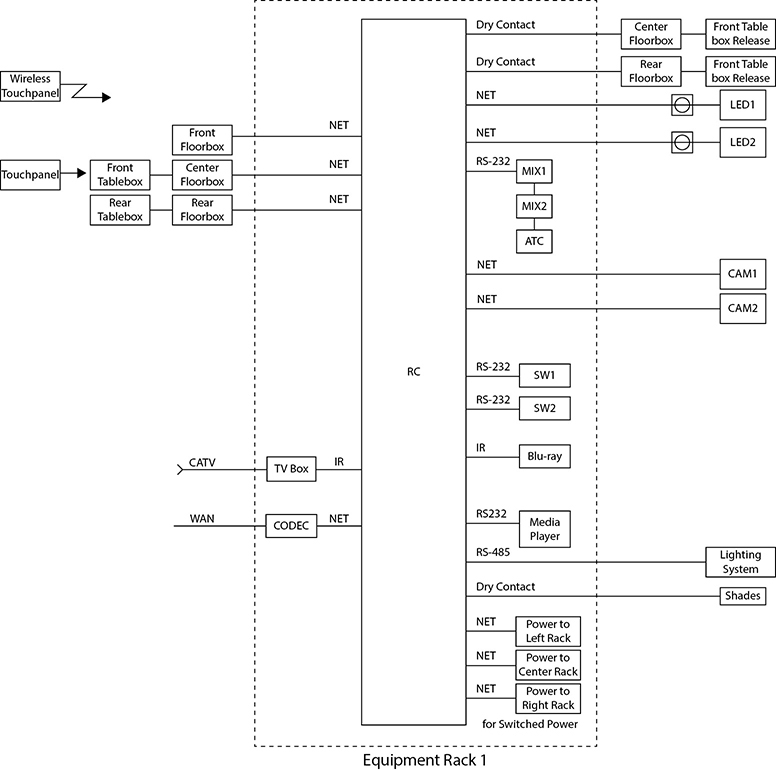
Figure 13-1 Example of a control system signal flow diagram
The process for creating a control system flow or function diagram is similar to the process for creating general system diagrams, such as audio or video “block” diagrams. The designer must determine how to represent control systems in drawings and how much detail is required in flow diagrams and in the schematic or wiring diagrams.
Installing Control Systems
Installers need to know which devices are being used and how they will connect to and interact with the system. Set aside some time to briefly discuss with the programmer the overall software design concepts.
The design plan should indicate the following:
• Required equipment
• Cable types
• Termination types
• Mounting types and methods
• Equipment address settings
• Button-by-button interface specifications
Open and inspect each piece of equipment; check for any damage and power on the device to verify that it is in good physical condition.
Use the software design plan to assign addresses and operating modes to the equipment as required. There are several ways to assign operating modes and addresses. Using a local HTTP (web browser) interface, manufacturer-specific configuration applications, dip switches, and jumpers are the common methods. Always RTFM for each piece of equipment in the system before attempting to configure it. After setting the addresses and operating modes, mark the settings on a label on the backside of the gear for future reference. Not only will this help if there are several pieces of the same model to install, but it makes it easy to determine what settings have been established on each device without searching through menus.
One hour of testing in the workshop before moving the equipment to the installation site may save many hours of troubleshooting in the field. Therefore, whenever possible, configure and test each device in the workshop. Verifying settings and performance of the system components in the workshop allows the technicians to interact with many of those involved in the project. User interface designs can be verified, troubleshooting is less time consuming, programmers have more time to fix any problems, and clients have a functional control system quicker.
If you must assemble and configure the control system at the client site, you should, at a minimum, set a brief meeting time with the designer and software programmer for review or questions.
Control system installation follows similar preparation guidelines as audio and video systems. However, the complexity of control systems requires special attention be given to any design layouts, signal flow diagrams, IP addressing information, and other technical documentation.
While installing a control system, strive to develop a positive relationship with the software programmers, system designer, and IT professionals involved in the project. Effective interaction with these people helps to assure that the control system is installed and configured correctly.
Installing Firmware
The control system must have the correct firmware and software properly installed and configured to achieve the required performance. From time to time, new firmware is made available to remove existing firmware bugs, accommodate changed hardware in new models of the equipment, add new system functionality, and improve operating performance.
At the workshop, confirm that the equipment has the latest firmware installed. Use the equipment manual to check the version numbers, consult the manufacturer’s website for the current version, and update as necessary. It is better to upgrade firmware in the workshop than at the customer’s site, since the required resources are probably more accessible in the office than in the field.
The control programs are the unique action scripts written for a specific install project. There may be separate scripts for the controller and devices such as switchers, DSPs, touch screens and control panels; each of these scripts must be installed on their respective devices. The manufacturers of the equipment may have proprietary software for loading the scripts onto the devices. Always refer to the software manual for the installation process: RTFM.
Make a special effort to ask the software programmer if there are any “hidden” or service pages, buttons, or modes in the device UIs that allow the technician to configure passwords, startup sequences, and other technical settings. Such service and technical interfaces will be included in the documentation provided by the designer. Asking about these technician interfaces can save you time configuring the system.
Verifying the Control System
Verifying the control system is an extremely important task. You should receive a list of what a control system is supposed to do from the control programmers. Once you have this list, you will need to press every button and test every trigger in the control system, one at a time. Check every single option to make sure it does what it is supposed to do. If the button or interface does not do what it is supposed to do, you will need to note that it is not right. Keep a detailed list of malfunctioning items for the system designer, programmers, and any involved members of the project management team. They can look through the list, examine the original specifications for the system, and make a decision if it is actually “broken.” If there is a problem, you or your project manager may need to fill out a change order.
Inspect and configure each control system and controlled device before installation of the AV system. If you have time, connect the system together as completely as possible and verify its operation.
Use the design plan to confirm the locations of all the control devices in the room. Then, go through a final system check. Here is a checklist:
• Verify that all cables are connected correctly according to the drawings. Modify drawings or connections as needed.
• Confirm that termination pin-outs are correct.
• Power up the control processor and connected devices.
• Verify that all required device selection buttons in the UI are available. For example, if the button for a media player is activated, the switcher selects the correct input.
• Verify that the correct buttons appear for the operation of each device selected. For example, if the button for a media player is touched, the appropriate controls, such as “play” and “pause,” should appear.
• Confirm that each device’s UI action buttons perform the specified action in accordance with the button-by-button specification.
• Test all buttons, control switches, motion sensors, infrared sensors, screen mechanisms, projector lifts, and other devices that interface with the system. This process can take several hours.
• Document all irregularities and anomalies, and report them to the programmers immediately.
• Confirm lighting presets in accordance with design specs and applicable lighting standards.
• Confirm audio presets in accordance with design specs and applicable listening standards.
• Confirm video presets in accordance with design specs and viewing standards.
• Test streaming connections and cloud data sources.
• Test conference connections for audio- and videoconferencing.
The installer must document any changes requested by the client; however, do not commit to any changes without clearance from your project manager.
Troubleshooting Control Systems
Because control systems are often complex and involve interaction between equipment from different manufacturers, they are likely to be a source of problems.
Take a look at a couple of problematic scenarios, possible causes, and solutions presented here.
Problem 1 A selection is made on a handheld remote and nothing happens.
Possible causes and solutions:
• Are the batteries in the transmitter dead? Change or recharge the batteries.
• Is the transmitter actually transmitting? Check IR devices with a digital camera. Check the RF receivers for traffic or signal indications.
• Is the addressing (unique identification) of the transmitter, receiver, or controlled component incorrect? Correctly address all components.
• If the control system has a CPU and control panels, have the appropriate operating software and action scripts been loaded into these devices and successfully initialized? If not, load the program software and action scripts and initialize all devices.
• Is the RF or IR receiver located inside the rack greatly reducing the range at which it can read the transmitter’s signal? Place the transmitter in close proximity to the receiver to see whether this improves its effectiveness.
• Is there a programming error? If this is the case, you will need to coordinate with the programmers to troubleshoot.
Problem 2 A device in the control system is not working or is working erratically. For example, a projector will not change inputs on command.
Possible causes and solutions:
• Is the cable carrying control information to the projector connected to the wrong output port on the control system? Check the appropriate port connection and make the change.
• Is the cable correctly connected; is it wired incorrectly or damaged? Check the pin-outs at both ends of the cable. Verify continuity of all active conductors and verify that there are no shorts between conductors created by staples, solder drips, cable ties, or other causes.
• Is there a programming error? If you suspect an error in programming, make every effort to confirm that it is a programming error and not an operational or configuration error, as calling back programmers can be time consuming and expensive (and potentially embarrassing if you made a wrong diagnosis). If it is a programming error, you will need to work with the programmers to troubleshoot it.
• Is the communications protocol for the device you are trying to control correctly configured? Verify the protocol in the device and operating system manuals—RTFM.
• Is the control port on the receiving device enabled?
• Have you followed all of the manufacturers’ instructions? RTFM.
Talking Control with the Customer
When dealing with the customer and you encounter a discrepancy between what a UI control does and what the documentation says it should do, only write down what the button did. Do not say “This function is broken” or “This control should do…” to the customer.
Let’s say you have installed a new control system. When you push “play,” the control system checks to see whether the projection screen is down and the projector is on. It then lowers the screen, turns on the projector, waits two minutes, and starts the movie. Before you check it on your documentation, your customer says, “That button should also dim the lights and adjust the volume.” If you say, “Yes, you are right,” without knowing what your company has agreed to do, your company may have to program all of the customer’s new requests, whether they agreed and intended to or not.
Performance Verification Standard
As you learned in Chapter 11, the ANSI/AVIXA 10:2013 Standard for Audiovisual Systems Performance Verification provides a framework and supporting processes for determining elements of an audiovisual system that need verification. As shown in Figure 13-2, this standard has a section dedicated to control performance verification.
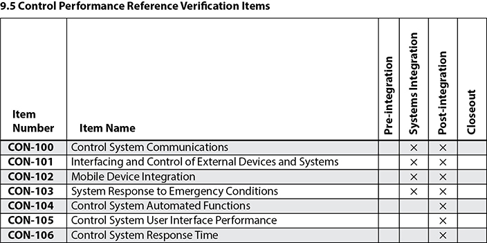
Figure 13-2 Control performance verification items from the ANSI/AVIXA 10:2013 Standard for Audiovisual Systems Performance Verification
The tasks on the checklist are
• 100 Verify that all control communications are tested from endpoint to endpoint via the appropriate midpoint(s) for operation and functionality as defined in the project documentation.
• 101 Verify that AV control system interfaces to and from control systems provided by others conform to requirements as defined in the project documentation.
• 102 Verify that mobile devices that are to be supported are integrated and operating as defined in the project documentation.
• 103 Verify that any required response of the installed audiovisual system(s) in the event of a life safety or similar emergency operates in accordance with local regulations and as defined in the project documentation. This item specifically excludes sound system response to an emergency condition, which is covered under item AP-100, Emergency Muting.
• 104 Verify that all time-dependent or automated functions executed by the control system conform to requirements as defined in project documentation.
• 105 Verify that the control system is implemented in a manner consistent with the requirements as defined in the project documentation.
• 106 Verify that the control system provides the user response time and maximum latency defined in the project documentation. This verification item should require a metric to be verified.
Verifying the performance of control systems according to established standards will help you assure overall system performance. You will learn about audio and video system verification in the chapters that follow.
Chapter Review
In this chapter you studied how control systems work and how to set them up for networked AV equipment.
Upon completion of this section, you should be able to do the following:
• Identify the documentation used when installing a control system
• Identify the process for installing control program hardware and software
• Verify that the control system works as expected
Remember that the primary purpose of control systems is to make complex AV systems more accessible.
Control systems allow users to focus on communicating a message. Any control system that is connected to a network can become a very powerful tool for device management and delivery of content. If control systems are built according to the client’s needs, using input from IT professionals and proper selection of devices, the final control system will be easy to use.
Review Questions
The following questions are based on the content covered in this chapter and are intended to help reinforce the knowledge you have assimilated. These questions are similar to the questions presented on the CTS-I exam. See Appendix E for more information on how to access the free online sample questions.
1. What is a control system?
A. A strategy for managing workgroups
B. An authorization policy
C. A system for managing a network
D. An interface between a human and a machine or system
2. Which of the following can control systems operate remotely? (Choose all that apply.)
A. Power
B. Drapes/curtains
C. Display monitors
D. Lights
3. Which of the following are elements of a control system? (Choose all that apply.)
A. Firmware
B. Hardware
C. Software
D. Spyware
4. What is a macro?
A. A function activated by a button
B. A set or sequence of functions activated by a single button
C. Multiple functions activated by separate buttons
D. A single function activated by a switch
5. Which of the following is a compiled program?
A. Machine code
B. DVD titles
C. RAW codec
D. Control script
6. Which type of control system provides device operation by opening or closing an electrical current or voltage loop?
A. IR control
B. Contact closure
C. RF control
D. Serial control
7. Which of the following are limitations of an IR control system? (Choose all that apply.)
A. It does not provide feedback that commands have been executed.
B. It requires direct line of sight to the device’s control point.
C. It may be subject to interference from ambient light.
D. It always requires batteries.
8. Which of the following is true of an IP control system?
A. It can be connected to equipment over the LAN.
B. It works with all models of equipment.
C. It is slower than serial control systems.
D. It runs machine code only.
9. Why is it better to test control systems in the workshop? (Choose all that apply.)
A. It allows more time to fix problems.
B. It may provide better access to help from internal teams.
C. It allows time for longer breaks.
D. It prevents customers from asking questions.
10. What should you do after setting the control address of a device?
A. Mark the equipment with this information
B. Erase this information from the system documentation
C. Give the customer an encrypted list of these settings
D. Back them up by posting them on your blog
Answers
1. D. A control system is the interface between a human and a machine or system.
2. A, B, C, D. Control systems can operate power and drapes/curtains and display monitors and lights remotely.
3. A, B, C. Firmware, hardware, and software are elements of a control system.
4. B. A macro is a set or sequence of functions activated by a single button.
5. A. A compiled program is machine code.
6. B. Contact closure control provides device operation by opening or closing an electrical current or voltage loop.
7. A, B, C. Only these three descriptions state the limitations of an IR control system.
8. A. An IP control system can be connected to and operate devices over the LAN.
9. A, B. It is better to test control systems in the workshop because you will have more time to fix problems and have access to help from internal teams.
10. A. After setting the control address of a device, you should mark the device with this information.