
5
Porous Organic Polymers as a Molecular Platform for Designing Porous Carbons
Qing Xu Qiuhong Jiang and Donglin Jiang
National University of Singapore, Department of Chemistry, Faculty of Science, 3 Science Drive 3, Singapore, 117543, Singapore
5.1 Introduction
Design and synthesis of porous materials are an important aspect of chemistry and materials science. Recent progress over the past three decades in polymer chemistry has made great effects on the molecular design and synthesis of porous polymers [1–6]. Especially, the advancement in designing porous polymers with organic building blocks has greatly increased the accessibility of porous architecture and expanded the structural scope of porous polymers [7–11]. Porous organic polymers are organic polymers with network skeletons and inherent pores. They are mainly composed of carbon and hydrogen, together with heteroatoms, such as boron, oxygen, nitrogen, sulfur, and phosphorus. In addition to their specific physiochemical properties and functions, these carbon‐rich skeletons with diverse heteroatoms and inherent pores make them attractive as a platform for designing and synthesizing porous carbon materials. Porous carbons have shown great potential in developing unique materials for catalysis, energy storage, and energy conversion [12–14]. In this sense, porous organic polymers could offer an indispensable platform for achieving metal‐free porous carbon materials. Porous organic polymers, depending on their structures, can be classified into porous aromatic frameworks (PAFs) [15–17], conjugated microporous polymers (CMPs) [18–20], hyper‐cross‐linked polymers (HCPs) [21–23], covalent triazine frameworks (CTFs) [24–26], and covalent organic frameworks (COFs) [27–30]. They are designed using different strategies to possess ordered or amorphous structures of various organic building blocks. In this chapter, we focused on reviewing the design, synthesis, and functions of porous carbons based on these porous organic polymers, by elucidating structural effects of porous organic polymers on resulting porous carbons. Moreover, we discuss the challenging issues to be addressed and feature directions from the perspectives of chemistry and materials science.
5.2 Porous Carbons Derived from Porous Aromatic Frameworks
PAFs are a class of PAFs with tetraphenylmethane vertices and various different linkages [15–17]. Based on Yamamoto reaction, tetrakis(4‐bromophenyl)methane has been polymerized into PAF‐1 (Figure 5.1) that exhibits a Brunauer–Emmett–Teller (BET) surface area as high as 5300 m2 g−1, a pore volume of 2.43 cm3 g−1, and a pore size of 1.44 nm. PAF‐1 was composed of 94.73% carbon and 5.27% hydrogen; the high content of carbon and high porosity render PAF‐1 to be able to serve as a precursor for the synthesis of porous carbons.
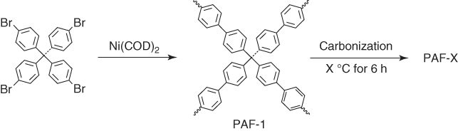
Figure 5.1 Schematic of the synthesis of PAF‐1 and the pyrolysis of PAF‐1 at different temperatures into porous carbons PAF‐1‐350, PAF‐1‐380, PAF‐1‐400, and PAF‐1‐450.
PAF‐1 was pyrolyzed under a controlled N2:O2 (98.1 : 1.5 in vol.) atmosphere at different temperatures of 350, 380, 400, and 450 °C for 6 h to yield various different porous carbons, i.e. PAF‐1‐350, PAF‐1‐380, PAF‐1‐400, and PAF‐1‐450, respectively [31]. Upon pyrolysis, these porous carbons did not show the vibration bands owing to the CH bonds in PAF‐1, as evidenced by Fourier transform infrared spectroscopy (FTIR). The surface area sharply decreased from 4033 (PAF‐1‐350) to 2881 (PAF‐1‐380), 2292 (PAF‐1‐400), and 1191 m2 g−1 (PAF‐1‐450), as the pyrolysis temperature was increased from 350 to 380, 400, and 450 °C, respectively. Along with the decrement of the BET surface areas, their pore volumes decreased from 2.06 to 1.51, 0.88, and 0.53 cm3 g−1, respectively. Moreover, the pore size decreased from 1.35 (PAF‐1‐350) to 1.27 (PAF‐1‐380), 1.18 (PAF‐1‐400), and 1.00 nm (PAF‐1‐450).
The CO2 adsorption capacity of PAF‐1 is 46 cm3 g−1 at 273 K. Upon pyrolysis, the capacity of the resulting porous carbons is highly dependent on the pyrolysis temperature. For example, PAF‐350 exhibited an increased capacity of 69 cm3 g−1 under otherwise identical conditions. The capacity further increased to 75.2 and 82.4 cm3 g−1 for PAF‐380 and PAF‐400, respectively. Notably, the CO2 adsorption capacity of PAF‐1‐450 is as high as 100 cm3 g−1, which is almost twofold that of PAF‐1. These comparative studies suggest that PAF‐1‐450 is more suitable for CO2 capture. The adsorption heat of PAF‐1 is 15.6 kJ mol−1, which increases to 21.1, 23.6, 26.7, and 27.8 kJ mol−1 for PAF‐1‐350, PAF‐1‐380, PAF‐1‐400, and PAF‐1‐450, respectively. These results indicate that the increased capacity of PAF‐1‐450 originates from increased interactions between the carbon skeletons and CO2 that has high quadrupole moment. In relation to its high capacity, the adsorption selectivity of CO2:N2 (15 : 85 CO2:N2) is 209, whereas the selectivity of CO2:CH4 is 7.89, and the selectivity of CO2:H2 (20 : 80 CO2:H2) at 273 K and 1 bar is 392, respectively.
The porous carbons prepared by pyrolysis of PAF‐1 under pure nitrogen atmosphere have been investigated with an aim to show its potential as an electrocatalytic cathode for oxygen reduction reaction (ORR) [32]. The development of high‐performance cathode materials for ORR is a key to fuel cells, whereas the electrocatalytic cathodes based on porous carbons require the combination of conductivity, porosity, and heteroatom diversity. Direct pyrolysis of PAF‐1 loses all the weight before 900 °C, as shown by thermal gravimetric analysis (TGA). As an optimized method, PAF‐1 was pretreated at 350 °C under N2 for 3 h and was further pyrolyzed at different temperatures of 600, 800, and 1000 °C for 1 h to yield PAF‐Carbon‐600, PAF‐Carbon‐800, and PAF‐Carbon‐1000, respectively (Figure 5.2). Among these carbons, PAF‐Carbon‐800 exhibited the highest graphitization degree (IG:ID) of 1.07, together with a large BET surface area of 418 m2 g−1 and a pore volume of 0.24 cm3 g−1. The ORR performance based on chronoamperometric measurements of cyclic voltammetry (CV) with rotating ring disk electrode (RRDE) in an aqueous KOH solution (0.1 M) revealed that PAF‐Carbon‐800 possesses the highest half‐wave potential of 0.68 V among this series of porous carbons.
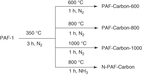
Figure 5.2 Schematic of the synthesis of PAF‐Carbons and N‐doping PAF‐Carbon from PAF‐1 at different temperatures.
After pretreated at 350 °C, the samples were pyrolyzed under NH3 atmosphere to yield a porous N‐PAF‐Carbon, which exhibited an increased porosity of 764 m2 g−1, a pore volume of 0.45 cm3 g−1, and a nitrogen content of 4.1%. Notably, N‐PAF‐Carbon exhibited an enhancement of the half‐wave potential (0.75 V) by approximately 70 mV compared with PAF‐Carbon‐800 (0.68 V) and improved limiting current (4.30 mA cm−2) by 80% (2.39 mA cm−2 for PAF‐Carbon‐800). This half‐wave potential of N‐PAF‐Carbon is only 44 mV less than that of the commercial Pt/C. Moreover, N‐PAF‐Carbon is almost free of CO and methanol crossover effects and holds better long‐term durability compared with the commercial Pt/C.
The possibility of supercapacitive energy storage using these porous carbons has been investigated for PAF‐Carbon‐800 and N‐PAF‐Carbon. The capacitance of N‐PAF‐Carbon at a current density of 0.5 A g−1 is as high as 135 F g−1, which is far superior to that (75 F g−1) of PAF‐Carbon‐800. Interestingly, N‐PAF‐Carbon is stable in cycle performance after 9000 charge–discharge cycles at a current density of 5 A g−1. The enhanced performance originates from the improved conductivity (resistance = 0.20 Ω), as well as the decreased pore size of 1.09 nm that is much closer to the size of electrolyte ions. These results indicate that the control of pyrolysis environment and temperature is quite important for producing PAFs‐derived, high‐performance porous carbons.
5.3 Porous Carbons Derived from Conjugated Microporous Polymers
CMPs are a unique class of porous amorphous polymers in which organic units are covalently linked in a π‐conjugated manner. This structural feature that enables the combination of the π conjugation and microporosity in one polymer is hardly achieved with other porous polymers. The carbon‐rich skeletons of CMPs with a diversity of heteroatoms serve as a promising platform for designing porous carbons. Indeed, various approaches have been developed for pyrolyzing various CMPs into porous carbons that exhibit a broad range of functions ranging from ORR catalysts to capacitive energy storage.
A series of nitrogen‐rich building blocks, including triphenyl amine, triphenyl triazine, terthiophene triazine, and tetraphenylporphyrin, have been employed to build CMPs, COP‐2, COP‐4, COP‐T, and COP‐P, respectively, via Yamamoto reaction (Figure 5.3) [33]. These CMPs were pyrolyzed under an inert atmosphere at 950 °C to yield N‐doped graphitic carbons, namely C‐COP‐X (X = 2, 4, P; pyrolysis temperature = 950 °C).
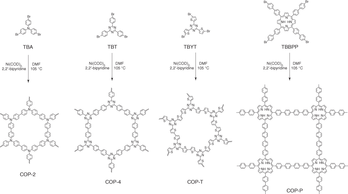
Figure 5.3 Schematic of the synthesis of N‐rich COP precursors using nickel‐catalyzed Yamamoto‐type Ullmann cross‐coupling reaction.
Unlike their precursors, C‐COP‐X exhibited powder X‐ray diffraction (PXRD) pattern with a pronounced peak at 26° assigned to the (002) facet, suggesting the formation of graphitic carbons upon pyrolysis. From the CV measurements in an aqueous KOH solution (0.1 M), C‐COP‐4 exhibited an ORR peak at the most positive potential of 0.79 V (versus reversible hydrogen electrode (RHE)) among the C‐COP‐X series. Linear sweep voltammetric (LSV) measurements on a ring disk electrode (RDE) revealed that C‐COP‐4 exhibits an onset potential similar to that of the Pt/C catalyst. The half‐wave potential of C‐COP‐4 reaches 0.78 V, which is close to that (0.80 V) of Pt/C. The transferred electron numbers per O2 molecule for C‐COP‐4 calculated using the Koutecky–Levich (K–L) equation are 3.90 at 0.55–0.70 V, which are the same level as that (3.88) calculated using the RRDE curves. Notably, C‐COP‐4 possesses high tolerance against CO and methanol and shows long‐term durability.
Different from metal‐free CMP precursors, the use of metalloporphyrin‐based CMPs as precursors could introduce not only nitrogen heteroatoms but also non‐noble metals such as Fe, Co, and Mn to the porous carbons [34]. As shown in Figure 5.4, porous carbons, i.e. C‐COP‐P‐M (M = Fe, Co, and Mn), have been synthesized by pyrolysis of their corresponding metalloporphyrin CMPs at 950 °C. Indeed, X‐ray photoelectron spectroscopic (XPS) analysis revealed the presence of metal‐bonded N and pyrrolic‐N atoms. The CV measurements in an aqueous KOH solution (0.1 M) show that C‐COP‐P‐M (M = Fe and Co) serves as an electrocatalyst with more positive ORR potentials of 0.77 V compared with the metal‐free C‐COP‐P (peak potential of 0.49 V versus RHE). From the LSV curves, the C‐COP‐P‐Fe electrode exhibited an onset potential similar to that of the commercially available Pt/C (0.98 V versus RHE), whereas the C‐COP‐P‐Co electrode exhibited a higher limited current than that of Pt/C. Interestingly, these C‐COP‐P‐M electrodes are almost free from the methanol crossover effect. Moreover, the C‐COP‐P‐M electrodes under acidic condition exhibited a much better stability than the Pt/C electrode and they are free of the methanol crossover/CO‐poisoning effects.

Figure 5.4 The incorporation of non‐precious metals (Fe, Co, and Mn) into C‐COP. Owing to the poor solubility of the synthesized COP materials in most common solvents, it is difficult to introduce metals into the COP‐P.
Similarly, another metalloporphyrin‐based CMP has been developed as the precursors for porous carbons [35]. The CoP‐CMP framework (Figure 5.5a) synthesized by the Yamamoto polycondensation reaction of 5,10,15,20‐tetrakis(4′‐bromophenyl)porphyrin‐Co(II) ([p‐Br]4PCo) exhibited the BET surface area of 1158 m2 g−1, a pore volume of 0.36 cm3 g−1, and a pore size of 3.87 nm. CoP‐CMP adopts ribbon‐like monoliths with a width of several micrometers and a length up to tens of micrometers. Pyrolysis of CoP‐CMP at 600, 800, and 1000 °C yielded CoP‐CMP‐600, CoP‐CMP‐800, and CoP‐CMP‐1000, respectively. Surprisingly, this pyrolysis process yielded the cobalt nanoparticles that were uniformly embedded in the matrix of nanofibers, as evidenced by high‐resolution transmission electron microscopy (HR‐TEM). As the pyrolysis temperature increased, the BET surface areas decreased from 508 m2 g−1 (CoP‐CMP‐600) to 480 (CoP‐CMP‐800) and 229 m2 g−1 (CoP‐CMP‐1000), which can be attributed to the structural collapse and rearrangement of the CoP‐CMP skeletons. Similarly, the N content decreased from 8.9 wt% (CoP‐CMP‐600) to 7.5 wt% (CoP‐CMP‐800) and 3.5 wt% (CoP‐CMP‐1000) as the pyrolysis temperature increased from 600 to 800 and 1000 °C. As an ORR catalyst, CoP‐CMP‐800 exhibited a more positive onset potential (−0.12 V) than CoP‐CMP‐600 (−0.15 V) and CoP‐CMP‐1000 (−0.14 V) in an aqueous KOH solution (0.1 M). Furthermore, CoP‐CMP‐800 yielded a highly stable diffusion‐limiting current (4.6 mA cm−2), which is superior to Pt/C. CoP‐CMP‐800 in an aqueous H2SO4 solution (0.5 M) exhibited a much more positive onset potential (0.74 V) than CoP‐CMP‐600 (0.63 V) and CoP‐CMP‐1000 (0.70 V). Surprisingly, CoP‐CMP‐800 achieves a diffusion‐limiting current of 4.8 mA cm−2. Therefore, these metal‐nanoparticle‐doped porous carbons are significant because they exhibit excellent catalytic activity and stability under both alkaline and acidic conditions.
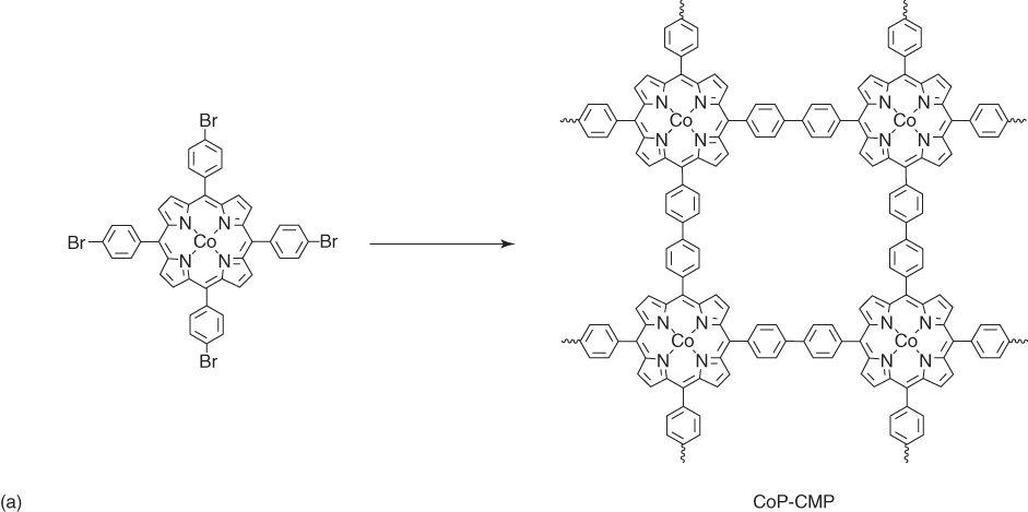

Figure 5.5 (a) Schematic of the synthesis of CoP‐CMP by Yamamoto coupling reaction and (b) schematic of the synthesis of 3D CoPOP.
The Sonogashira–Hagihara coupling reactions of cobalt(II) porphyrin and a 3D linker with a 93% specificity yielded a 3D porous CMP, i.e. CoPOP (Figure 5.5b), which possesses a BET surface area of 1069 m2 g−1 and a pore size of 1.5 nm [36]. Pyrolysis of CoPOP under Ar at 600, 800, and 1000 °C yielded CoPOP‐600, CoPOP‐800, and CoPOP‐1000 with BET surface areas of 686, 764, and 602 m2 g−1, respectively. These porous carbons have the same average pore size of 1.3 nm. As electrocatalysts, CoPOP‐800 on black carbon exhibited the highest ORR catalytic activity under acidic (0.5 M H2SO4) and alkaline (0.1 M KOH) conditions. It shows the diffusion‐limited current densities of 5.30 and 5.35 mA cm−2 and the half‐wave potential of 0.681 and 0.825 V under acidic and alkaline conditions, respectively. These performances are comparable with those of commercial Pt/C (20%) that shows the half‐wave potential of 0.737 and 0.829 V under acidic and alkaline conditions, respectively. Moreover, CoPOP‐800 on black carbon shows excellent stability, retaining 76% and 95% of the initial current density after 13.9 h under both acidic and alkaline conditions. By contrast, the retaining percentage of the current of Pt/C was only 47% and 15% under otherwise identical conditions. Moreover, CoPOP‐800 on carbon black is robust against methanol poisoning by showing almost no current decrease upon addition of methanol.
Metalloporphyrin‐based CMPs have been further investigated for the preparation of porous carbons, whereas two different metal species are integrated into one CMP skeleton upon co‐polycondensation of two metalloporphyrin monomers [37]. For example, PCN‐FeCo, a bimetallic CMP with iron(III) and Co(II) in the scaffold, has been synthesized by co‐polycondensation of TIPP‐Fe and TEPP‐Co via Sonogashira reaction (Figure 5.6). Upon pyrolysis at 800 °C, the resulting porous carbon PCN‐FeCo/C could retain the sheet‐like structure of the PCN‐FeCo precursor. HR TEM images revealed the coexistence of onion‐like graphitic nanoshells and metal nanoparticles. The BET surface area of PCN‐FeCo/C is 930 m2 g−1, which is only slightly decreased from that (1260 m2 g−1) of the PCN‐FeCo precursor. The porous structure has been confirmed by measuring CO2 adsorption isotherms. PCN‐FeCo/C exhibited a CO2 uptake of 71.3 and 46.1 cm3 g−1 at 273 and 298 K, respectively, which are close to that (78.4 at 273 K and 47.3 cm3 g−1 at 298 K) of the PCN‐FeCo precursor. Thus, the morphology and porous structure are well retained upon pyrolysis. The peak potential of PCN‐FeCo/C for ORR in an aqueous KOH solution (0.1 M) reaches 0.88 V, which is higher than that (0.86 V) of PCN‐CoCo/C and PCN‐FeFe/C. RDE in an O2‐saturated aqueous KOH solution (0.1 M) at a scan rate of 10 mV s−1 revealed that the bimetallic PCN‐FeCo/C has a more positive onset potential (1.00 V) than that of PCN‐FeFe/C (0.97 V) and PCN‐CoCo/C (0.92 V), suggesting the importance of the binary metal system. Moreover, PCN‐FeCo/C exhibited a high half‐wave potential of 0.85 V and a highly stable diffusion‐limiting current of 5.5 mA cm−2, which are comparable with those of Pt/C (0.84 V and 5.3 mA cm−2). PCN‐FeCo/C exhibited the highest activity among the series under acidic condition (0.1 M HClO4) to show the positive onset of 0.90 V and a half‐wave potential of 0.76 V. The ORR polarization curve of PCN‐FeCo/C in an aqueous HClO4 solution (0.1 M) is nearly identical to that of the Pt/C catalyst. Moreover, PCN‐FeCo/C has shown a good durability and methanol tolerance. The prominent performance of PCN‐FeCo/C originates from its structural features including large surface area, substantial graphitization, and high density of uniformly distributed heterometallic active species.

Figure 5.6 Schematic diagram of the synthesis of PCN‐MM from TIPP‐M and TEPP‐M monomers (M = Fe and Co).
Another type of bimetallic porphyrin‐based CMP, i.e. Fe/Co‐CMP, has been synthesized using Suzuki polycondensation reaction, whereas Fe‐CMP and Co‐CMP with the same Fe(III) or Co(II) species in the skeletons have been prepared as controls using a similar method (Figure 5.7) [38]. The BET surface areas of Fe/Co‐CMP, Fe‐CMP, Co‐CMP, and metal‐free CMP are 463, 597, 488, and 352 m2 g−1, respectively. These CMPs were pyrolyzed at 700, 800, and 900 °C, etched with hydrochloric acid (6.0 M) for 16 h, and subjected to a second pyrolysis to yield M‐CMP‐700, M‐CMP‐800, and M‐CMP‐900, respectively. From the ORR polarization plots, the most suitable pyrolysis temperature was observed for 800 °C. The onset potential increased in the following order: Co‐CMP‐800 (0.82 V), Fe‐CMP‐800 (0.85 V), and Fe/Co‐CMP‐800 (0.88 V). Fe/Co‐CMP‐800 has a positive half‐wave potential of 0.76 V, which is higher than that (0.74 V) of Co‐CMP‐800 and Fe‐CMP‐800, and is only 0.08 V less than that of Pt/C. Compared with Fe‐CMP‐800 that shows a limiting current density of 3.3 mA cm−2, Fe/Co‐CMP‐800 has a much higher current density of 4.5 mA cm−2. The bimetallic Fe/Co‐CMP‐800 catalyst has a similar stability to the commercial Pt/C catalyst.

Figure 5.7 Schematic of the synthesis and structure of Fe/Co‐CMP via Suzuki polycondensation.
As described above, a variety of CMPs have been developed for the pyrolytic synthesis of porous carbon. Nevertheless, CMPs with controlled morphology have been rarely explored. Using graphene sheets to sandwich CMPs, graphene‐based CMP sheets (GMPs) have been developed (Figure 5.8) [39]. In order to synthesize such a sandwich structure, graphene oxide (GO) was reduced with hydrazine hydrate to form reduced graphene oxide (RGO), which was functionalized with para‐bromophenyl groups on surface by treating with a p‐bromobenzene diazonium salt to yield RGBr. These bromophenyl units served as anchors and were reacted with 2,5‐dibromothiophene, 2,5‐dibromo‐1,3‐thiazole, and 2,6‐dibromopyridine to form CMP‐S, CMP‐NS, and CMP‐N between graphene sheets to yield the sandwich products of GMP. The resulting GMP was pyrolyzed under Ar at 800 °C to yield graphene‐based microporous carbon (GMC). As control, CMP‐S, CMP‐NS, and CMP‐N without graphene sandwich structure were directly carbonized to yield MC‐S, MC‐N, and MC‐NS, respectively. The morphology and microstructure of the GMP were investigated by FE‐SEM, HR‐TEM, and atomic force microscopy (AFM), confirming a sheet morphology. The BET surface areas of CMP‐S, CMP‐NS, and CMP‐N are 689, 458, and 522 m2 g−1, respectively, whereas the BET surface areas of GMP‐S, GMP‐NS, and GMP‐N increased to 888, 818, and 591 m2 g−1, respectively. These increased surface areas originate from the 2D structure of graphene sheets. Upon pyrolysis, the BET surface areas of GMC‐S, GMC‐NS, and GMC‐N decreased to 618, 681, and 560 m2 g−1. From the XPS analysis, the sulfur content in GMC‐S and GMC‐NS was 7.7 and 5.9 wt%, respectively, whereas the nitrogen content in GMC‐NS and GMC‐N reached 3.0 and 3.8 wt%, respectively, suggesting that these porous carbons have high heteroatom doping levels. The ORR catalytic activity of the GMCs was evaluated by CV in an aqueous KOH solution (0.1 M). GMC‐S exhibited the ORR onset potential of −0.15 V and the peak potential of −0.28 V (versus Ag/AgCl), which were slightly lower than those of GMC‐NS and GMC‐N respectively. From the K–L plots and RRDE curves, the numbers of transferred electrons were evaluated to be close to 4, confirming a four‐electron pathway in the ORR process. The half‐wave potential for the ORR with GMC‐S is −0.23 V, which is 52 mV lower than that of MC‐S without graphene sandwich. Similarly, GMC‐NS and GMC‐N exhibited a decrease in the half‐wave potential in comparison with that of their corresponding MC‐NS (97 mV) and MC‐N (90 mV). Notably, GMCs exhibited outstanding supercapacitive energy storage performance. The specific gravimetric capacitances of GMCs at a current density of 0.1 A g−1 are between 244 and 304 F g−1, which are 14–35% higher than those of MCs. The enhanced ORR and capacitive energy storage performance can be attributed to the high conductivity of graphene in the sandwich structures. This work thus offers a way to various 2D graphene hybrids with heteroatom‐doped carbons.
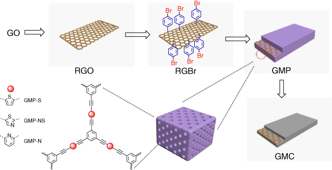
Figure 5.8 Schematic of GMPs and related graphene‐based microporous carbons (GMCs).
Integrating CMPs onto carbons with different dimensionalities to form different hybrids is an interesting approach to porous carbons. Different carbon materials include (0D carbon spheres (CSs)), 1D single‐walled carbon nanotubes (1D SWNTs), and 2D RGO with bromophenyl groups functionalized on their surfaces, which serve as anchors to integrate boron‐ and nitrogen‐containing BODIPY units into CMPs via Sonogashira–Hagihara reaction (Figure 5.9), to produce CMP‐0D, CMP‐1D, and CMP‐2D, respectively [40]. The BET surface areas of CMP‐0D, CMP‐1D, and CMP‐2D are 622, 614, and 593 m2 g−1, respectively, which are slightly higher than that (574 m2 g−1) of amorphous CMP (Amor‐BN). They have a similar pore diameter of 1.6 nm. CMP‐2D was pyrolyzed at different temperatures of X °C (X = 700, 800, 900, and 1000 °C) for 2 h under an argon atmosphere, yielding boron‐ and nitrogen‐co‐doped porous carbons 2DBN‐X. The electrocatalytic activities of 2DBN‐X in ORR under alkaline conditions (0.1 M KOH) were examined by CV. 2DBN‐800 exhibited an ORR peak potential of 0.69 V versus RHE, which is the highest among the four analogs. Based on the LSV curves under 1600 rpm, 2DBN‐800 exhibited the lowest half‐wave‐potential (0.81 V) and the highest diffusion‐limited current density (JDL = −6.0 mA cm−2), respectively. From LSV plots, it is clear that the JDL value decreased from 5.95 to 4.94 and 3.98 mA cm−2 and the electron transfer numbers decreased from 3.85 to 3.69 and 3.03, as the carbon dimensionality was decreased from 2 (2DBN‐800) to 1 (1DBN‐800) and 0 (0DBN‐800). The enhanced catalytic performance observed for 2DBN‐800 is likely correlated with the improved conductivity because 2D structure has a large lateral and layer‐to‐layer conducting pathway compared with that of the dot‐to‐dot and line‐to‐line conductive pathways of 0D and 1D carbons.
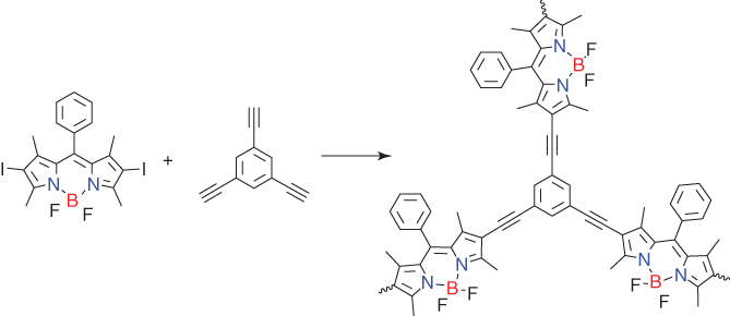
Figure 5.9 Schematic of the synthesis of the B,N‐contained CMP that is pyrolyzed into dimension‐controlled carbons.
In addition to the ORR electrocatalytic activity, these porous carbons serve as air cathode in Zn–air batteries. To fabricate primary Zn–air batteries, the porous carbons were loaded onto carbon fiber paper and paired with a Zn foil as an anode using an aqueous KOH solution (6 M) as an electrolyte. The battery exhibited an open‐circuit voltage of 1.40 V. At a voltage of 0.8 V, AmorBN‐800, 0DBN‐800, 1DBN‐800, and 2DBN‐800 displayed the current density of 7, 5, 15, and 17 mA cm−2, respectively. The peak power densities for AmorBN‐800, 0DBN‐800, 1DBN‐800, and 2DBN‐800 at 9.7, 6.7, 21.2, and 23.9 mA cm−2 reach 6.9, 4.8, 13.2, and 14.6 mW cm−2, respectively. Notably, the batteries with the 2DBN‐800 cathode exhibited outstanding cycling stability, which retains the capacitance upon charged–discharge cycle for 11 h with a 5‐min cycling period at a high current density of 20 mA cm−2. This performance is superior to rechargeable batteries using a commercial Pt/C cathode.
Transition metal dichalcogenides (TMDs) are a class of 2D inorganic materials that have been explored as the template to prepare porous 2D hybrid carbons [41]. To overcome the problem of low solubility, chemically exfoliated MoS2 was functionalized with 4‐iodophenyl diazonium salt under aqueous conditions to yield MoS2‐I. The resulting MoS2‐I can be well dispersed in various organic solvents, such as dimethylformamide and toluene. MoS2‐I was reacted with monomers of N‐heterocycles such as pyridine, pyrimidine, and triazine to yield 2D hybrid materials M‐CMP1, M‐CMP2, and M‐CMP3, respectively. These 2D hybrid materials were pyrolyzed at different temperatures (T) of 700, 800, and 900 °C for 2 h, to yield M‐CMPs‐T (Figure 5.10). The FE‐SEM, HR‐TEM, and AFM images confirmed that M‐CMPs adopt similar sheet‐like structures. The BET surface areas of M‐CMP1, M‐CMP2, and M‐CMP3 are 1625, 1254, and 1058 m2 g−1, respectively, which are higher than those for CMP1 (1086 m2 g−1), CMP2 (886 m2 g−1), and CMP3 (392 m2 g−1) without MoS2.
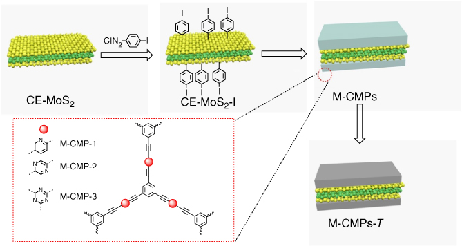
Figure 5.10 Schematic of the synthesis of M‐CMPs‐T from MoS2 and N‐rich CMPs.
Upon pyrolysis, the M‐CMPs‐T hybrids preserved nanosheet morphology as revealed by the FE‐SEM and HR‐TEM images. The BET surface areas of M‐CMPs‐T are as high as 790–850 m2 g−1, whereas the pore sizes are between 1.1 and 3.5 nm; these results indicate that the porous structure is well retained upon pyrolysis. XPS analysis confirmed that M‐CMP1‐800, M‐CMP2‐800, and M‐CMP3‐800 have a high N content of 2.8, 3.6, and 3.1 wt%, respectively. M‐CMP2‐800 exhibited the highest peak current density at the most positive potential of −0.21 V (versus Ag/AgCl). From the LSV profiles, the diffusion‐limited currents of the commercial Pt/C, M‐CMP1‐800, M‐CMP2‐800, and M‐CMP3‐800 at −0.6 V were estimated to be 5.5, 4.7, 5.4, and 3.4 mA cm−2, respectively. Based on the RRDE curves, the electron transfer numbers of M‐CMP2‐800 are 3.8, which are higher than those of M‐CMP1‐800 (3.6) and M‐CMP3‐800 (3.3). Moreover, the specific gravimetric capacitance of M‐CMP2‐800 was calculated to be 344 F g−1 at 0.2 A g−1, which is 1.3 times as high as that (237 F g−1) of CMP2‐800 and is higher than those of MoS2‐based capacitors, such as 1 T phase MoS2, hollow MoS2 nanospheres, and MoS2/graphene hybrid. The superior ORR and supercapacitor performances suggest a synergistic interaction between MoS2 and porous carbon layers to create a hierarchical porous structure, which facilitates electrolyte penetration and ion diffusion.
As described above, most CMPs have been synthesized using coupling reactions that employ harsh conditions, such as high temperature, long reaction time, and noble‐metal‐based catalysts. Recently, CMPs with high N content have been synthesized by oxidative polymerization under mild conditions (Figure 5.11) [42]. The designed CMPs, i.e. PTCT, PTCA, and PBCP, were synthesized by oxidizing the building blocks with FeCl3 in a nitromethane/chloroform mixture at room temperature under air. PTCT, PTCA, and PBCP have the BET surface area of 895, 1020, and 399 m2 g−1, and the pore size of 0.75, 1.08, and 1.03 nm, respectively. PTCT, PTCA, and PBCP at 273 K and 1 bar exhibited CO2 uptake of 99.7, 66.5, and 34.9 cm3 g−1, which corresponds to a capacity of 19.6, 13.1, and 6.9 wt%, respectively.
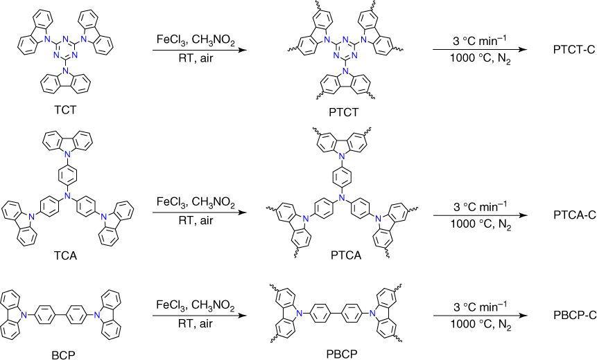
Figure 5.11 Schematic of the synthesis of polycarbazole networks and their derived carbons.
Pyrolysis of PTCT, PTCA, and PBCP at 1000 °C under N2 resulted in PTCT‐C, PTCA‐C, and PBCP‐C, respectively, in 75–80 wt% yields. The elemental analyses revealed that PTCT‐C, PTCA‐C, and PBCP‐C have a high N content of 6.1, 3.6, and 3.0 wt%, possess the BET surface area of 1280, 910, and 790 m2 g−1, and hold pores with the size of 0.71, 0.93, and 0.94 nm, respectively. The specific capacitances of PTCT‐C, PTCA‐C, and PBCP‐C are 558, 385, and 290 F g−1 at a current density of 1.0 A g−1, as well as 492, 357, and 264 F g−1 at a current density of 2.0 A g−1, respectively. These results indicate that PTCT‐C with the highest surface area and nitrogen content has the highest electrochemical capacitance. The galvanostatic charge–discharge cycling at a current density of 2.0 A g−1 revealed that PTCT‐C retains 95% of its original capacitance upon 1000 cycles.
5.4 Porous Carbons Derived from Hyper‐Cross‐Linked Polymers
HCPs are amorphous porous polymer networks with inherent microporosity and low density. HCPs are facilely synthesized using Friedel–Crafts alkylation reaction that can proceed under mild conditions and employs inexpensive reagents. For example, three HCPs, i.e. HCP‐Ben, HCP‐Th, and HCP‐Py, have been synthesized from the Friedel–Crafts alkylation reaction of benzene, thiophene, and pyrrole, respectively (Figure 5.12) [43]. HCP‐Ben, HCP‐Th, and HCP‐Py have the BET surface area of 1382, 484, and 322 m2 g−1 and possess the total pore volume of 1.52, 0.33, and 0.25 cm3 g−1, respectively. Carbonized HCPs, including Ben750, Th850, and Py800, were prepared by mixing HCPs with KOH in a 1 : 4 ratio for pyrolysis at a temperature between 700 and 1000 °C, followed by extraction of residual salts. Ben750, Th850, and Py800 exhibited very high BET surface area of 3105, 2682, and 4334 m2 g−1, respectively. HCP‐Ben and HCP‐Th adsorb CO2 with a capacity of 1.6 and 1.3 mmol g−1 at 1 bar. Although HCP‐Py has the lowest BET surface area, it exhibited the highest CO2 uptake of 2.1 mmol g−1 at 1 bar, as a result of high‐nitrogen‐containing heterocycles in the porous polymer. Notably, Ben750, Th850, and Py800 at 1 bar exhibited enhanced CO2 adsorption capacity to reach 3.3, 2.4, and 3.5 mmol g−1, respectively. At high pressure, Py800 enhanced the capacity to 22.0 mmol g−1 at 298 K, whereas Ben750 and Th850 also exhibited high CO2 uptakes of 15.6 and 13.2 mmol g−1, respectively. Moreover, the H2 uptake capacity was significantly improved upon carbonization. HCP‐Ben, HCP‐Th, and HCP‐Py exhibited a H2 uptake capacity of 1.1, 0.9, and 1.0 wt%, respectively. By contrast, Ben750, Th850, and Py800 at 10 bar and 77.3 K achieved a high H2 uptake capacity of 4.0, 3.7, and 5.6 wt%, respectively.
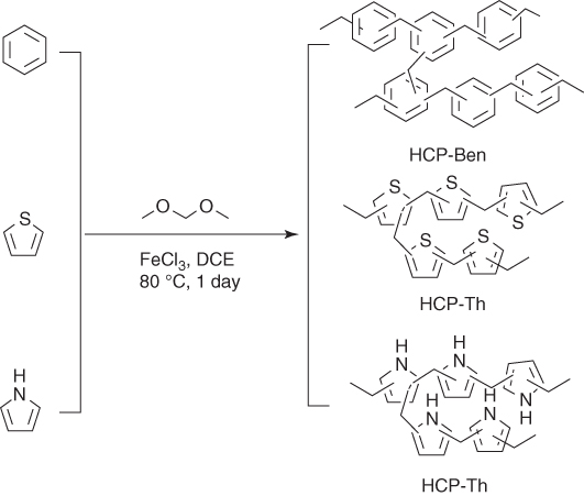
Figure 5.12 Schematic of the synthesis of HCPs from benzene, thiophene, and pyrrole.
5.5 Porous Carbons Derived from Covalent Triazine Frameworks
CTFs, owing to the presence of triazine units, are a unique class of nitrogen‐rich porous polymers that can be synthesized via the cyclotrimerization of nitrile units under ionothermal or microwave conditions [44]. Amorphous nitrogen‐rich networks, i.e. TNNs‐T, have been synthesized from terephthalonitrile at different temperatures (T = 400, 450, 500, 550, 600, 650, and 700 °C) under ionothermal conditions (Figure 5.13). The HR‐TEM images revealed that TNN‐500 is composed of uniform porous networks. Elemental analyses indicate that the nitrogen content of TNNs‐T decreased from 12.44% to 5.75%, as the temperature was increased from 400 to 700 °C, indicating that high reaction temperature results in a decreased nitrogen content. The N 1s XPS results of TNNs‐T revealed the presence of four distinct N configurations in the skeletons, i.e. pyridinic‐N (397.98–398.40 eV, N1), pyrrolic‐N (399.60–399.99 eV, N2), quaternary‐N (400.86–401.19 eV, N3), and N oxide (402.65–403.94 eV, N4). As a general tendency, a high reaction temperature decreases the N1 and N2 contents but increases the N3 and N4 contents. From nitrogen adsorption–desorption isotherm curves, TNN‐400 exhibited a typical type I plot, indicating that TNN‐400 contains only micropores. As the reaction temperature was increased, the nitrogen adsorption–desorption isotherm curves gradually changed from type I to type IV, which suggests the propagation of mesopore formation. The capacitive energy storage was conducted in an aqueous H2SO4 solution (1 M). From the CV curves, TNN‐550 exhibited the highest current density among the series. The specific capacitances at a current density of 0.2 A g−1 are 248, 276, 285, 298, 263, 272, and 243 F g−1 for TNN‐300, TNN‐400, TNN‐500, TNN‐550, TNN‐600, TNN‐700, and TNN‐800, respectively. From the Nyquist plots, the resistances were evaluated to be 3.66, 2.68, 1.88, 1.49, 1.53, and 1.53 Ω for TNN‐400, TNN‐450, TNN‐550, TNN‐600, TNN‐650, and TNN‐700, respectively. From these results, it can be concluded that at a temperature between 300 and 550 °C, a higher reaction temperature decreases the resistance; at a temperature above 550 °C, a higher reaction temperature decreases the N content and degrades the redox reactions and the surface wettability. Notably, the TNNs‐550 electrode at a current density of 10 A g−1 did not show deterioration in performance after 5000 cycles.

Figure 5.13 Schematic of the synthesis of TNNs‐T using ionothermal method (T is the reaction temperatures of 400, 450, 500, 550, 600, 650, and 700 °C).
Heteroatom and micropores play roles in the capacitive energy storage. In order to elucidate these two effects, a new strategy has been developed for the synthesis of porous materials with well‐defined heteroatom content and pore size distribution [45]. Porous triazine‐based frameworks (PTFs) were synthesized from 1,3,5‐tricyanobenzene at different temperatures of 550, 600, 650, and 700 °C to yield PTF‐550, PTF‐600, PTF‐650, and PTF‐700, respectively. The BET surface area increased from 1212 to 1419, 1964, and 2482 m2 g−1 for PTF‐550, PTF‐600, PTF‐650, and PTF‐700, respectively, whereas the corresponding effective electroactive surface areas increased from 508 to 600, 850, and 1154 m2 g−1. PTF‐700 exhibits a quasi‐rectangular shaped CV curve, whereas the CV plots of PTF‐650, PTF‐600, and PTF‐550 gradually changed to a fusiform, indicating a better high‐rate capability. Surprisingly, the specific capacitances of these PTFs are almost same between 147.1 and 151.3 F g−1 at a current density of 0.1 A g−1. According to the equation of C = εS/d, where C is the capacitance, ε is the relative permittivity, and S is the effective electroactive surface areas, high reaction temperature results in a low ε value. Pore size distribution profiles revealed that all the pores (smaller than 4 nm) increased as the reaction temperature was increased. On the other hand, the N content decreased sharply from 17.67% to 7.67%. Therefore, the dominant factor that leads to the decrement of the ε value is the decreased N content in PTFs at an elevated reaction temperature. Therefore, a high reaction temperature improves the conductivity and the rate capability; the drop of nitrogen content at higher reaction temperatures results in a decreased surface functionality. The excellent high‐rate capability renders PTF‐700 to be able to work in the potential range of 0–3.5 V and to achieve the energy and power densities of 62.7 and 8750 W kg−1, respectively. The PTF‐700‐based supercapacitor after charged at 3.5 V is able to drive commercially available white light‐emitting diode (LED) or red LED at 2.2 V. Notably, PTF‐700 retains 85% of its original capacitance after 10 000 cycles at a high current density of 7 A g−1.
In addition to supercapacitors, CTF‐derived carbons have been developed for applications as a catalyst in ORR [46]. 2D CTF was pyrolyzed to form 3D TTF at different temperatures of 400, 500, 600, and 700 °C to yield TTF‐400, TTF‐500, TTF‐600, and TTF‐700, respectively (Figure 5.14). The nitrogen contents of these 3D TTFs are 12.44, 10.74, 9.07, and 5.75 wt% and the BET surface areas are 1175, 1681, 2197, and 2237 m2 g−1, respectively. The ORR activities of these 3D TTFs were evaluated by the CV in O2‐ and Ar‐saturated aqueous KOH solution (0.1 M). Both the onset potential and the reduction peaks showed positive shift with an increased pyrolysis temperature, indicating a better ORR performance of carbons prepared at high temperature. The LSV curves confirmed that TTF‐700 has the most positive onset potential of 0.822 V (versus RHE) and possesses the highest diffusion‐limiting current density of 4.63 mA cm−2. Because thermal treatment has a great influence on the ORR catalytic performance, another two carbons of TTF‐700‐1 and TTF‐700‐96 were prepared by pyrolysis at 700 °C for 1 and 96 h, respectively. TTF‐700‐1 and TTF‐700‐96 have a similar high BET surface area of 2597 and 2849 m2 g−1, respectively. The total N content decreased obviously from 9.3 (TTF‐700‐1) to 4.1 wt% (TTF‐700‐96), with an increased N3 content from 28.78% to 38.10%. TTF‐700‐96 exhibited much positive and higher limit current density than TTF‐700‐1, which suggests that TTF‐700‐96 has a better catalytic activity in ORR. The electron transfer numbers of TTF‐700‐96 are between 3.8 and 4 that are bigger than those (3–4) of TTF‐700‐1 calculated based on the K–L equations, suggesting that TTF‐700‐96 has a higher selectivity toward total oxygen reduction. The ORR catalyzed by TTF‐700‐96 is dominated by the one‐step, four‐electron pathway. These results suggest the importance of the N3 content in ORR.
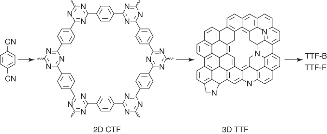
Figure 5.14 Schematic of the synthesis of heteroatom‐doped carbons from 2D CTF.
To further improve the catalytic performance, TTF‐700‐96 was doped with B and F atoms to yield TTF‐B and TTF‐F by reacting with boron oxide and ammonium fluoride at 600 °C in the presence of ZnCl2. The B content of TTF‐B is 1.28 atom% and the F content of TTF‐F is 1.62 atom%, respectively. The BET surface area of TTF‐F (2570 m2 g−1) is comparable with that of TTF‐700‐96 (2849 m2 g−1). By contrast, the BET surface area of TTF‐B (1694 m2 g−1) is much low. The pore size distributions of TTF‐B and TTF‐F are almost the same as that of TTF‐700‐96. TTF‐B exhibited almost the same onset potential and limited current density as those of TTF‐700‐96. The corresponding electron transfer numbers of TTF‐B are from 3.7 to 3.8 that are bigger than those (from 3.3 to 3.7) of TTF‐700‐96 through the RRDE measurements, indicating an improved catalytic selectivity. Surprisingly, the half‐wave potential of TTF‐F reaches 0.767 V that is close to 0.78 V of the commercial 20% Pt/C catalyst, and the limited current density is 6.15 mA cm−2 that has surpassed that (5.4 mA cm−2) of Pt/C catalyst. Additionally, the HO2− yield of TTF‐F decreased to 15%, whereas the corresponding electron transfer numbers increased to 3.7. Moreover, TTF‐F did not show apparent attenuation after a 40 000‐s test, which is in sharp contrast to the commercial Pt/C with a reduction by 30%. Upon addition of methanol, TTF‐F did not show a change in the current density, whereas Pt/C exhibited an obvious drop in the current density.
It is highly desirable to explore electroactive organic materials as green cathodes for sustainable and cost‐effective lithium‐ion batteries (LIBs). Combining the high conductivity of graphene and tailor‐made pore structures of CTFs‐derived carbon, a CTF‐derived carbon has been developed for applications in LIBs [47]. The graphene porous polyaryltriazine‐derived frameworks, i.e. G‐PPFs, were synthesized by modification of RGO with Na to form RGONa, which served as initiators to trigger the anionic polymerization of acrylonitrile on the graphene surfaces to generate RGO‐PAN. RGO‐PAN with acetonitrile groups was reacted with oDCB, pDCB, and mDCB at different temperatures of 300, 400, and 600 °C under ionothermal conditions in the presence of ZnCl2 catalyst to yield G‐PPF‐p‐300, G‐PPF‐p‐400 (G‐PPF‐m‐400, G‐PPF‐o‐400), and G‐PPF‐p‐600, respectively (Figure 5.15). By contrast, G‐PPF‐p‐400‐600 was synthesized at 400 °C for 20 h and then 600 °C for 20 h. The decreased ID:IG values from Raman spectra of G‐PPF‐p‐400 (ID:IG = 0.92), G‐PPF‐p‐600 (ID:IG = 1.01), and G‐PPF‐p‐400‐600 (ID:IG = 1.02) compared with those of RGO (ID:IG = 1.25) indicate the lower defect density and the enhanced graphitic degree at a high reaction temperature. The FE‐SEM, HR‐TEM, and AFM images confirmed that 2D carbons assume a 2D morphology with uniform thickness. The BET surface areas of G‐PPF‐o‐400, G‐PPF‐m‐400, G‐PPF‐p‐400, G‐PPF‐p‐600, and G‐PPF‐p‐400‐600 are 651, 1238, 1285, 1414, and 1683 m2 g−1, respectively. The average pore sizes of G‐PPF‐o‐400, G‐PPF‐m‐400, G‐PPF‐p‐400, G‐PPF‐p‐400‐600, and G‐PPF‐p‐600 are 2.1, 2.5, 2.9, 3.7, and 7.3 nm, respectively. The low surface area of G‐PPF‐o‐400 is related to the formation of continuous porous frameworks as a result of steric hindrance exerted by the two ortho‐substituted nitrile groups.
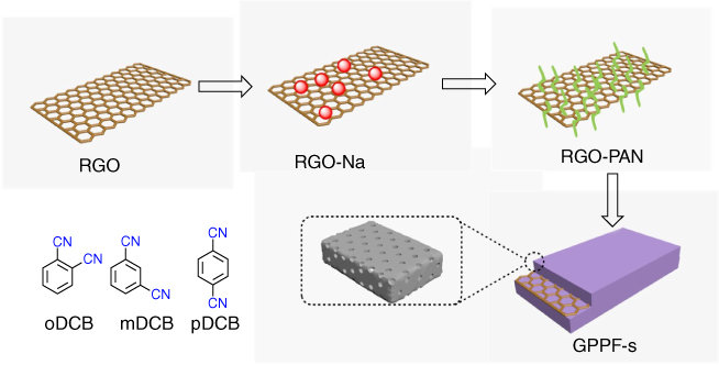
Figure 5.15 Schematic of the synthesis of G‐PPFs from RGO.
From the XPS analysis, the contents of N1 and N4 remain almost constant, whereas the content of N2 tends to decrease and the content of N3 increases significantly. The total N content of G‐PPF‐p‐400, G‐PPF‐p‐600, and G‐PPF‐p‐400‐600 is 9.1%, 7.7%, and 6.6%, respectively. To explore the electrochemical behavior of G‐PPFs as cathodes for LIBs, CV of G‐PPF‐p‐400‐600 was measured at a scan rate of 10 mV s−1 below and above the open‐circuit voltage of 3 V versus Li/Li+, thus ensuring that the electrode had either reversible p‐type (an oxidized state above 3 V versus Li/Li+) or n‐type (a reduced state below 3 V versus Li/Li+) redox activity. In the galvanostatic discharge‐charge measurements at a current density of 0.4 A g−1, the G‐PPF‐p‐400‐600 electrode delivers a high reversible capacity of 410 mAh g−1 after 800 cycles, which is better than other carbons in the series. The G‐PPF‐p‐400‐600 electrode exhibited prominent capacities of 460, 260, and 230 mAh g−1 at the current densities of 0.05, 0.8, and 3.2 A g−1, respectively. In each case, it achieves nearly 100% Coulombic efficiency. More importantly, the G‐PPF‐p‐400‐600 electrode can be operated up to 5100 cycles with a reversible capacity of 395 mAh g−1 at a high current density of 5 A g−1. The excellent performance originates from the combined effects of (i) the enhanced conductivity from the RGO template, (ii) the high surface areas, and (iii) the retained electroactive properties in the redox‐active porous frameworks strongly coupled to the surface of graphene through covalent bonds.
5.6 Porous Carbons Derived from Covalent Organic Frameworks
COFs are a class of crystalline porous polymer with broad structural diversity and enable synthetic control over their topologies, building blocks, and pores [7, 10, 11]. COFs mainly comprise carbons and are versatile for integrating heteroatoms such as B, O, and N to the skeletons. The designable structure and abundant composition render COFs as useful precursors for the pyrolytic synthesis of heteroatom‐doped porous carbons.
A cobalt porphyrin COF, i.e. Co‐COF (Figure 5.16a), has been developed as a precursor for the pyrolysis preparation of a nanocomposite of Co (0) nanoparticles and graphitized carbons as catalysts for ORR. In an aqueous solution of KOH (0.1 M), both the potential and the current responds obtained for the pyrolyzed Co‐COF‐900 are comparable with those of the commercial 20% Pt/C catalyst. Based on the RRDE experiments, there are 3.85 electrons involved in ORR, demonstrating that the oxygen reduction catalyzed by pyrolyzed Co‐COF‐900 involves a four‐electron process [48].

Figure 5.16 Schematic of the synthesis of (a) Co‐COF and (b) 2DPPV.
In addition to the metal‐contained COFs, a metal‐free COF, i.e. 2D poly(phenylenevinylene) framework (2DPPV), has been explored as a precursor for the synthesis of porous carbons (Figure 5.16b) [49]. The BET surface area of 2DPPV is 472 m2 g−1, whereas the pore volume is 0.37 cm3 g−1 and the pore size is 1.6 nm. The FE‐SEM and AFM images revealed that 2DPPV adopts sheet‐like flakes with a thickness of 50–300 nm. 2DPPV was pyrolyzed at 700, 800, and 900 °C under an argon atmosphere to yield 2DPPV‐700, 2DPPV‐800, and 2DPPV‐900, respectively, whereas the 800 °C‐pyrolyzed carbon 2DPPV‐800 was further treated at 800 °C under an ammonia atmosphere for 15 min to yield 2DPPV‐800a. The resultant carbons exhibited high surface areas from 529 to 880 m2 g−1 (2DPPV‐800a). As a metal‐free ORR catalyst, 2DPPV‐800a exhibited a low onset potential of 0.85 V (versus RHE) and a four‐electron pathway under alkaline conditions (0.1 M KOH). Apart from ORR performance, these carbons exhibited good performance in capacitive energy storage. The specific capacitance of 2DPPV‐800 was as high as 334 F g−1 at a current density of 0.5 A g−1, which is increased by 85% and 27% compared with those of 2DPPV‐700 and 2DPPV‐900, respectively. 2DPPV‐800 could retain its high capacitance after 10 000 galvanostatic charge–discharge cycles at the current density of 0.5 A g−1.
Electrical double‐layer supercapacitors feature high power density, short charging time, excellent reversibility, and long cycle stability. These supercapacitors do not require redox‐active building units. Heteroatoms such as oxygen, nitrogen, fluorine, or phosphorus are effective to improve the capacitive energy storage performance. In this sense, COF‐derived carbons offer promising electrode materials for supercapacitors [50]. For example, the dried COF‐5 sample was mixed with ZnCl2 and ground uniformly. The resulting mixture was pyrolysis at 700 °C, to yield a B‐doped porous carbon, i.e. BC‐MS‐700‐14 (Figure 5.17). BC‐MS‐700‐14 has a high surface area of 1460 m2 g−1 and a high pore volume of 1.76 cm3 g−1, whereas the direct carbonization product (BC‐700) in the absence of ZnCl2 has a low BET surface area of 449 m2 g−1 and a low pore volume of 0.26 cm3 g−1. BC‐MS‐700‐14 exhibited a specific capacitance of 160 F g−1 at a scan rate of 10 mV S−1 and 140 F g−1 at 50 mV S−1 in an aqueous H2SO4 solution (1 M), which are much higher than those of BC‐700 under otherwise conditions.
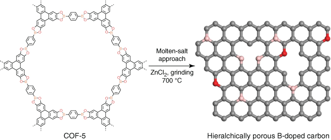
Figure 5.17 Schematic of the synthesis of B‐doped carbons upon pyrolysis of COF‐5.
Pre‐functionalization with metal ions is another effective method to improve the surface area after pyrolysis [51]. For example, the imine linkage in COFs offers an ideal receptor to coordinate metal ions (Figure 5.18). The RT‐1‐COF was vigorously stirred in a methanol solution of metal–salt M(acac)n (M = Fe3+, Co2+, Ni2+; acac = acetylacetonate) to form COF‐1‐M (M = Fe(II), Co(III), and Ni(IV)). The resulting COF‐1‐M samples were pyrolyzed under a N2 atmosphere at 900 °C for 4 h to yield N‐doped graphene ((N)G‐M). (N)G‐2 has the highest BET surface area of 1147 m2 g−1, which is much higher than that of RT‐1‐COF (329 m2 g−1) and COF‐1‐M (620 m2 g−1). The CVs of (N)G2‐4 in an aqueous KOH solution (6 M) exhibited a rectangular shaped profile, even at a high scan rate of 500 mV s−1, which indicates a remarkable high‐rate capability. The specific capacitance of (N)G‐2 is 460 F g−1 at a current density of 1 A g−1, whereas the (N)G3 and (N)G4 samples have a decreased capacitance of only 160 and 125 F g−1, respectively. Nyquist plots revealed that (N)G2 has a near vertical line within the low‐frequency region, indicating a better capacitive behavior. (N)G2 retained 90% of its original capacitance after 10 000 charge–discharge cycles.
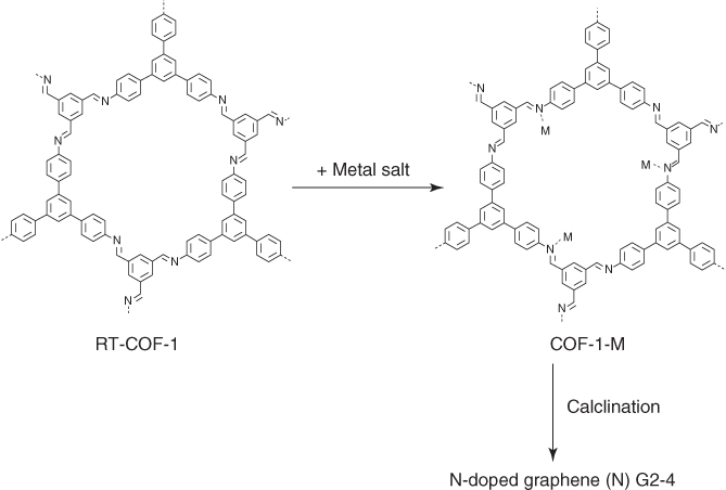
Figure 5.18 Schematic of synthesis of N‐doped graphene from RT‐COF‐1 by metal‐functionalization approach.
Hollow CSs are attractive owing to their distinct features, including low density, good thermal stability, and permeability. COFs have been developed for the preparation of hollow CSs doped with metal and nitrogen [52]. For example, the imine‐linked LZU‐1 upon binding with Pd2+ through the imine linkages forms Pd@LZU‐1, which was pyrolyzed at 500 and 600 °C to yield Pd@NHCS(500) or Pd@NHCS(600) with Pd nanoparticles in the N‐doped hollow CSs (Figure 5.19). Pd@NHCS(500) or Pd@NHCS(600) has the BET surface areas of 468 or 527 m2 g−1, respectively. Pd@NHCS(500) or Pd@NHCS(600) was employed to catalyze the hydrogenation of nitrobenzene to aniline. Compared with Pd@NHCS(600), Pd@NHCS(500) exhibited higher catalytic activity; the hollow structure of Pd@NHCS(600) tends to break and cause the formation of aggregated Pd nanoparticles, which results in a decreased catalytic activity. Notably, Pd@NHCS(500) could be regenerated and cycle used at least five times without obvious loss of catalytic activity and selectivity.
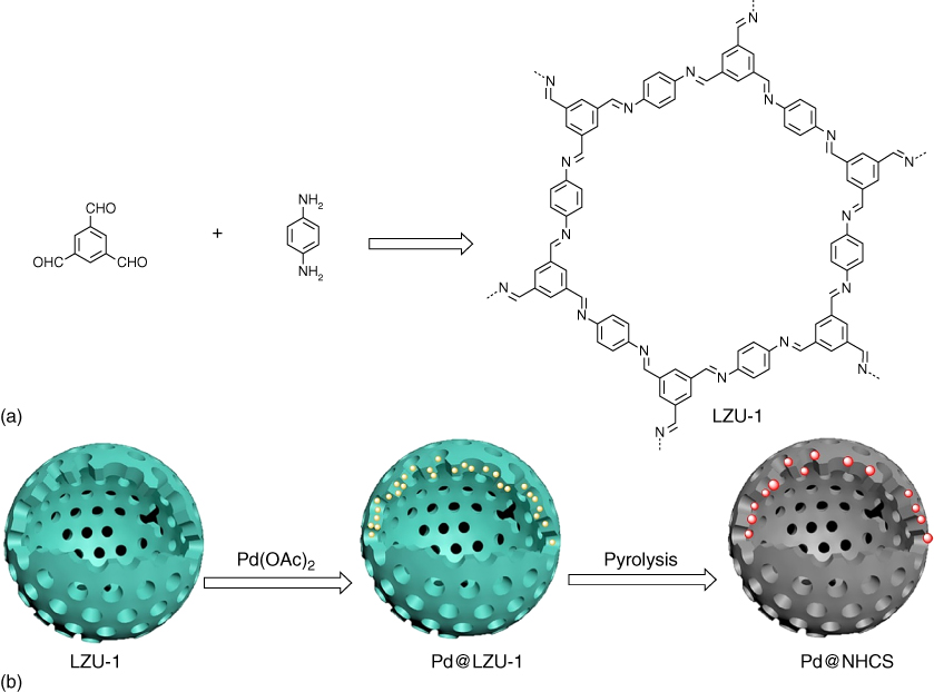
Figure 5.19 Schematic of (a) synthesis of LZU‐1 and (b) the fabrication of Pd@NHCS.
5.7 Summary and Perspectives
Organic porous materials have been explored as an attractive platform for the design and synthesis of porous carbons, whose properties and functions are promising as electrodes for various types of energy storage, as electrocatalysts for energy conversion, and as heterogeneous catalysts for organic transformations. The elaborate structural designability, the high carbon density, and the broad heteroatom diversity observed for porous organic polymers constitute distinct structural features that are hardly achieved for other types of polymer precursors. As summarized in this chapter, studies on porous organic polymers have opened a new aspect to the chemistry of porous carbons and already shown their great potential for structural control and functionalization of porous carbons.
From the perspective of chemistry, the correlation of porous organic structures with porous carbons is an important subject that deserves further investigation. Especially, the precise design of and synthetic control over the skeletons and pores are still far to be reached for most porous organic polymers. Researches along this direction would encourage the exploration of new reactions, catalysts, and building blocks. Moreover, control over the pyrolysis process is highly desired, but it remains a substantial challenge. In this sense, to retain and/or merge the structural features of porous precursors such as porosity and heteroatom density into the porous carbons is worthy of further investigations. From a materials perspective, exploration of facile process for large‐scale synthesis of well‐defined porous organic polymers is a subject of interest. The development of methods that enable the efficient conversion of these precursors into porous carbons with desired and/or tailor‐made structures is an ultimate target of this emerging field.
References
- 1. Stock, N. and Biswas, S. (2012). Synthesis of metal‐organic frameworks (MOFs): routes to various MOF topologies, morphologies, and composites. Chem. Rev. 112: 933–969.
- 2. Wu, D., Xu, F., Sun, B. et al. (2012). Design and preparation of porous polymers. Chem. Rev. 112: 3959–4015.
- 3. Das, S., Heasman, P., Ben, T., and Qiu, S. (2017). Porous organic materials: strategic design and structure–function correlation. Chem. Rev. 117: 1515–1563.
- 4. Lu, W., Wei, Z., Gu, Z.‐Y. et al. (2014). Tuning the structure and function of metal‐organic frameworks via linker design. Chem. Soc. Rev. 43: 5561–5593.
- 5. Hasell, T. and Cooper, A.I. (2016). Porous organic cages: soluble, modular and molecular pores. Nat. Rev. Mater. 1: 16053.
- 6. Slater, A.G. and Cooper, A.I. (2015). Function‐led design of new porous materials. Science 348: aaa8075.
- 7. Huang, N., Wang, P., and Jiang, D. (2016). Covalent organic frameworks: a materials platform for structural and functional designs. Nat. Rev. Mater. 1: 16068.
- 8. Xu, Y., Jin, S., Xu, H. et al. (2013). Conjugated microporous polymers: design, synthesis and application. Chem. Soc. Rev. 42: 8012–8031.
- 9. Tan, L. and Tan, B. (2017). Hypercrosslinked porous polymer materials: design, synthesis, and applications. Chem. Soc. Rev. 46: 3322–3356.
- 10. Feng, X., Ding, X., and Jiang, D. (2012). Covalent organic frameworks. Chem. Soc. Rev. 41: 6010–6022.
- 11. Waller, P.J., Gándara, F., and Yaghi, O.M. (2015). Chemistry of covalent organic frameworks. Acc. Chem. Res. 48: 3053–3063.
- 12. Zhang, J., Xia, Z., and Dai, L. (2015). Carbon‐based electrocatalysts for advanced energy conversion and storage. Sci. Adv. 1: e1500564.
- 13. Liu, J., Wickramaratne, N.P., Qiao, S.Z., and Jaroniec, M. (2015). Molecular‐based design and emerging applications of nanoporous carbon spheres. Nat. Mater. 14: 763–774.
- 14. Liu, X. and Dai, L. (2016). Carbon‐based metal‐free catalysts. Nat. Rev. Mater. 1: 16064.
- 15. Ben, T. and Qiu, S. (2013). Porous aromatic frameworks: synthesis, structure and functions. CrystEngComm 15: 17–26.
- 16. Díaz, U. and Corma, A. (2016). Ordered covalent organic frameworks, COFs and PAFs. From preparation to application. Coord. Chem. Rev. 311: 85–124.
- 17. Pei, C., Ben, T., and Qiu, S. (2015). Great prospects for PAF‐1 and its derivatives. Mater. Horiz. 2: 11–21.
- 18. Liu, X., Xu, Y., and Jiang, D. (2012). Conjugated microporous polymers as molecular sensing devices: microporous architecture enables rapid response and enhances sensitivity in fluorescence‐on and fluorescence‐off sensing. J. Am. Chem. Soc. 134: 8738–8741.
- 19. Zhou, Y.‐B., Wang, Y.‐Q., Ning, L.‐C. et al. (2017). Conjugated microporous polymer as heterogeneous ligand for highly selective oxidative heck reaction. J. Am. Chem. Soc. 139: 3966–3969.
- 20. Chen, L., Honsho, Y., Seki, S., and Jiang, D. (2010). Light‐harvesting conjugated microporous polymers: rapid and highly efficient flow of light energy with a porous polyphenylene framework as antenna. J. Am. Chem. Soc. 132: 6742–6748.
- 21. Abbott, L.J. and Colina, C.M. (2014). Formation of microporosity in hyper‐cross‐linked polymers. Macromolecules 47: 5409–5415.
- 22. Ding, L., Gao, H., Xie, F. et al. (2017). Porosity‐enhanced polymers from hyper‐cross‐linked polymer precursors. Macromolecules 50: 956–962.
- 23. Wang, S., Zhang, C., Shu, Y. et al. (2017). Layered microporous polymers by solvent knitting method. Sci. Adv. 3: e1602610.
- 24. Jung, S.‐M., Kim, D., Shin, D. et al. (2016). Unusually stable triazine‐based organic superstructures. Angew. Chem. Int. Ed. 55: 7413–7417.
- 25. Talapaneni, S.N., Hwang, T.H., Je, S.H. et al. (2016). Elemental‐sulfur‐mediated facile synthesis of a covalent triazine framework for high‐performance lithium–sulfur batteries. Angew. Chem. Int. Ed. 55: 3106–3111.
- 26. Kuhn, P., Antonietti, M., and Thomas, A. (2008). Porous, covalent triazine‐based frameworks prepared by ionothermal synthesis. Angew. Chem. Int. Ed. 47: 3450–3453.
- 27. Xu, H., Gao, J., and Jiang, D. (2015). Stable, crystalline, porous, covalent organic frameworks as a platform for chiral organocatalysts. Nat. Chem. 7: 905–912.
- 28. Xu, H., Tao, S., and Jiang, D. (2016). Proton conduction in crystalline and porous covalent organic frameworks. Nat. Mater. 15: 722–726.
- 29. Lin, S., Diercks, C.S., Zhang, Y.‐B. et al. (2015). Covalent organic frameworks comprising cobalt porphyrins for catalytic CO2 reduction in water. Science 349: 1208.
- 30. Jin, E., Asada, M., Xu, Q. et al. (2017). Two‐dimensional sp2 carbon–conjugated covalent organic frameworks. Science 357: 673–676.
- 31. Ben, T., Li, Y., Zhu, L. et al. (2012). Selective adsorption of carbon dioxide by carbonized porous aromatic framework (PAF). Energy Environ. Sci. 5: 8370.
- 32. Xiang, Z., Wang, D., Xue, Y. et al. (2015). PAF‐derived nitrogen‐doped 3D carbon materials for efficient energy conversion and storage. Sci. Rep. 5: 8307.
- 33. Xiang, Z., Cao, D., Huang, L. et al. (2014). Nitrogen‐doped holey graphitic carbon from 2D covalent organic polymers for oxygen reduction. Adv. Mater. 26 (20): 3315.
- 34. Xiang, Z., Xue, Y., Cao, D. et al. (2014). Highly efficient electrocatalysts for oxygen reduction based on 2D covalent organic polymers complexed with non‐precious metals. Angew. Chem. Int. Ed. 53: 2433–2437.
- 35. Wu, Z.S., Chen, L., Liu, J. et al. (2014). High‐performance electrocatalysts for oxygen reduction derived from cobalt porphyrin‐based conjugated mesoporous polymers. Adv. Mater. 26: 1450–1455.
- 36. Lu, G., Zhu, Y., Xu, K. et al. (2015). Metallated porphyrin based porous organic polymers as efficient electrocatalysts. Nanoscale 7: 18271–18277.
- 37. Lin, Q., Bu, X., Kong, A. et al. (2015). Heterometal‐embedded organic conjugate frameworks from alternating monomeric iron and cobalt metalloporphyrins and their application in design of porous carbon catalysts. Adv. Mater. 27: 3431–3436.
- 38. Brüller, S., Liang, H.‐W., Kramm, U.I. et al. (2015). Bimetallic porous porphyrin polymer‐derived non‐precious metal electrocatalysts for oxygen reduction reactions. J. Mater. Chem. A 3: 23799–23808.
- 39. Zhuang, X., Zhang, F., Wu, D. et al. (2013). Two‐dimensional sandwich‐type, graphene‐based conjugated microporous polymers. Angew. Chem. Int. Ed. 52: 9668–9672.
- 40. Zhuang, X., Gehrig, D., Forler, N. et al. (2015). Conjugated microporous polymers with dimensionality‐controlled heterostructures for green energy devices. Adv. Mater. 27: 3789–3796.
- 41. Yuan, K., Zhuang, X., Fu, H. et al. (2016). Two‐dimensional core‐shelled porous hybrids as highly efficient catalysts for the oxygen reduction reaction. Angew. Chem. Int. Ed. 55: 6858–6863.
- 42. Wang, H., Cheng, Z., Liao, Y. et al. (2017). Conjugated microporous polycarbazole networks as precursors for nitrogen‐enriched microporous carbons for CO2 storage and electrochemical capacitors. Chem. Mater. 29: 4885–4893.
- 43. Lee, J.M., Briggs, M.E., Hasell, T., and Cooper, A.I. (2016). Hyperporous carbons from hypercrosslinked polymers. Adv. Mater. 28: 9804–9810.
- 44. Hao, L., Luo, B., Li, X. et al. (2012). Terephthalonitrile‐derived nitrogen‐rich networks for high performance supercapacitors. Energy Environ. Sci. 5: 9747.
- 45. Hao, L., Ning, J., Luo, B. et al. (2015). Structural evolution of 2D microporous covalent triazine‐based framework toward the study of high‐performance supercapacitors. J. Am. Chem. Soc. 137: 219–225.
- 46. Hao, L., Zhang, S., Liu, R. et al. (2015). Bottom‐up construction of triazine‐based frameworks as metal‐free electrocatalysts for oxygen reduction reaction. Adv. Mater. 27: 3190–3195.
- 47. Su, Y., Liu, Y., Liu, P. et al. (2015). Compact coupled graphene and porous polyaryltriazine‐derived frameworks as high performance cathodes for lithium‐ion batteries. Angew. Chem. Int. Ed. 54: 1812–1816.
- 48. Ma, W., Yu, P., Ohsaka, T., and Mao, L. (2015). An efficient electrocatalyst for oxygen reduction reaction derived from a co‐porphyrin‐based covalent organic framework. Electrochem. Commun. 52: 53–57.
- 49. Zhuang, X., Zhao, W., Zhang, F. et al. (2016). A two‐dimensional conjugated polymer framework with fully sp2‐bonded carbon skeleton. Polym. Chem. 7: 4176–4181.
- 50. Huang, Y.‐B., Pachfule, P., Sun, J.‐K., and Xu, Q. (2016). From covalent–organic frameworks to hierarchically porous B‐doped carbons: a molten‐salt approach. J. Mater. Chem. A 4: 4273–4279.
- 51. Romero, J., Rodriguez‐San‐Miguel, D., Ribera, A. et al. (2017). Metal‐functionalized covalent organic frameworks as precursors of supercapacitive porous N‐doped graphene. J. Mater. Chem. A 5: 4343–4351.
- 52. Chen, L., Zhang, L., Chen, Z. et al. (2016). A covalent organic framework‐based route to the in situ encapsulation of metal nanoparticles in N‐rich hollow carbon spheres. Chem. Sci. 7: 6015–6020.