PIX-to-PIX Configuration
One advantage of using the PIX Firewall is that it has become a standard within the industry. As time passes, your business might acquire or become acquired by another company. To provide connectivity, you are faced with two choices: enabling VPNs over the Internet or using dedicated connections. Because one of the benefits of the PIX box is to allow secure VPNs, this section explores how to set up two PIX Firewalls between different locations through the Internet.
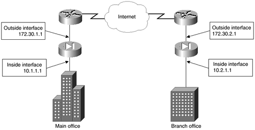
In this scenario, shown in Figure 4-10, assume that both companies trust each other totally. This means that you will not filter any traffic between the sites, and all hosts on both sites will be able to see all hosts on the other site. The peers use ISAKMP in Phase 1 to negotiate an IPSec connection in Phase 2.
As shown in Figure 4-12, the main office uses an internal IP address of 10.1.1.1/24 with an IP address of 172.30.1.1 on the outside interface. The branch office uses an internal IP address of 10.2.1.1/24 and an IP address of 172.30.2.1 on the outside interface. The following is the configuration for the PIX Firewall at the main office. After the configuration, you will see a discussion of the commands used.
Figure 4-12. PIX-to-PIX IPSec with ISAKMP Example

hostname mainofficepix
nameif ethernet0 outside security0
nameif ethernet1 inside security100
interface ethernet0 auto
interface ethernet1 auto
mtu outside 1500
mtu inside 1500
ip address outside 172.30.1.1 255.255.255.0
ip address inside 10.1.1.1 255.255.255.0
access-list 100 permit ip 10.1.1.0 255.255.255.0 10.2.1.0 255.255.255.0
nat (inside) 0 access-list 100
sysopt connection permit-ipsec
crypto ipsec transform-set maintransformset esp-des esp-md5-hmac
crypto map mymap 10 ipsec-isakmp
crypto map mymap 10 match address 100
crypto map mymap 10 set peer 172.30.2.1
crypto map mymap 10 set transform-set maintransformset
crypto map mymap interface outside
isakmp enable outside
isakmp key mysharedkey address 172.30.2.1 netmask 255.255.255.255
isakmp policy 10 authentication pre-share
isakmp policy 10 encryption des
isakmp policy 10 hash md5
isakmp policy 10 group 1
isakmp policy 10 lifetime 768
All of the preceding commands have been discussed previously within this chapter. There are only a few new items that you need to watch carefully to ensure that this configuration will work.
First, access list 100 must allow hosts from the branch office through the PIX Firewall. Limiting who is allowed through on the branch office network or which hosts that the branch office hosts are allowed to see is controlled through this access list. For example, assume that everyone except the branch manager in the branch office is allowed to connect only to the hosts at 10.1.1.14, 10.1.1.15, and 10.1.1.200. The branch manager, whose IP address is 10.2.1.53, is allowed to access all hosts on the main office network. In this case, your access list would be as follows:
access-list 100 permit ip 10.1.1.0 255.255.255.0 10.1.2.1.53 255.255.255.255
access-list 100 permit ip 10.1.1.14 255.255.255.255 10.2.1.0 255.255.255.0
access-list 100 permit ip 10.1.1.15 255.255.255.255 10.2.1.0 255.255.255.0
access-list 100 permit ip 10.1.1.200 255.255.255.255 10.2.1.0 255.255.255.0
Now take note of the use of the nat 0 command to prevent NAT from occurring. In some cases, you need to enable NAT because both sites are using the same nonroutable IP addresses. This is actually a common scenario. For example, without NAT enabled and both sites using the 10.1.1.0/24 network, both PIX Firewalls will not know which network to respond to when a packet is received.
Next, you set up the Phase 2 connection. Use the sysopt command with the permit-ipsec parameter to allow packets associated with this SA through the PIX Firewall. Set up the transform set for IPSec, assign a map to the access list, and set the interface for the crypto connection. You also use the crypto map command to set the peer for this connection. As always, the IP address of the peer should be the outside interface of the remote PIX Firewall.
As with any ISAKMP key exchange, you need to ensure that the interface chosen is appropriate, that the key is exactly the same on both peers, and that the encryption and hash types are identical between peers.
PIX-to-PIX with Identical Internal IP Addresses
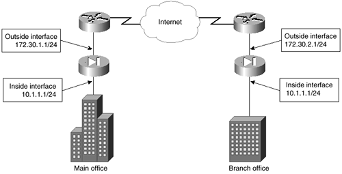
One of the issues raised by using a nonroutable IP address is the use of the IP address while another connected location is using that same address. This is a common issue when two companies connect to each other for the first time. Looking at Figure 4-13, notice that both the main and branch offices use the same internal IP address. In this situation, you will need to translate the addresses of both internal networks.
Figure 4-13. PIX-to-PIX with Identical Internal Network Addresses

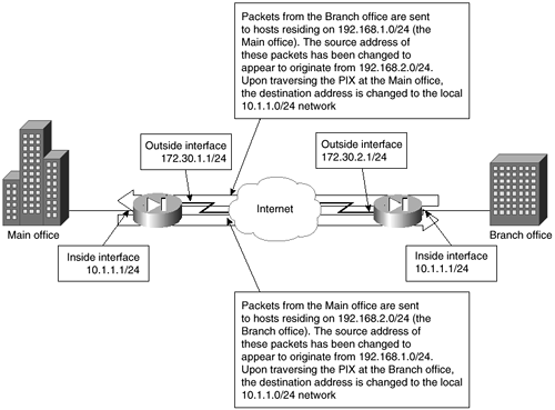
On the PIX at the main office, you will use NAT to translate all data destined for the branch office to the 192.168.1.0/24 network. The branch office translates all data destined for the main office to use 192.168.2.0/24 addresses. Therefore, from the point of view of the main office, the branch office appears to use 192.168.2.0/24. From the point of view of the branch office, the main office appears to use 192.168.1.0 as its internal IP addresses. Each PIX Firewall needs to be configured in a similar manner. Figure 4-14 shows how each office sees the other.
Figure 4-14. PIX-to-PIX with Each Side Using NAT

The listing of this configuration follows. This is virtually the same configuration as the previous example, with a few minor changes. First, you have to implement a global pool for use with NAT for data traveling to the branch office. Second, you have to remove the lines associated with the nat 0 command for data traveling to the branch office. Third, you have to create a new access list called nattobranch, which is used by NAT to change the source address of the packets so that these packets appear to originate from the 192.168.1.0/24 network.
hostname mainofficepix
nameif ethernet0 outside security0
nameif ethernet1 inside security100
interface ethernet0 auto
interface ethernet1 auto
mtu outside 1500
mtu inside 1500
ip address outside 172.30.1.1 255.255.255.0
ip address inside 10.1.1.1 255.255.255.0
global (outside) 1 192.168.1.1-192.168.1.253
global (outside) 1 192.168.1.254
access-list nattobranch permit ip 10.1.1.0 255.255.255.0 192.168.2.1 255.255.255.0
nat (inside) 1 access-list nattobranch
sysopt connection permit-ipsec
crypto ipsec transform-set maintransformset esp-des esp-md5-hmac
crypto map mymap 10 ipsec-isakmp
crypto map mymap 10 match address nattobranch
crypto map mymap 10 set peer 172.30.2.1
crypto map mymap 10 set transform-set maintransformset
crypto map mymap interface outside
isakmp enable outside
isakmp key mysharedkey address 172.30.2.1 netmask 255.255.255.255
isakmp policy 10 authentication pre-share
isakmp policy 10 encryption des
isakmp policy 10 hash md5
isakmp policy 10 group 1
isakmp policy 10 lifetime 768
