
Configuration Example
Now that you have seen an overview of the CSPM and the required basic installation requirements, this section will provide a simple configuration example. This example is based around a simple network with one Cisco Secure PIX Firewall and one Cisco Router running the Cisco IOS Firewall. The PIX is version 5.1(2) and the Cisco IOS Firewall is 12.0(7)T. Both of these are supported by the CSPM as policy enforcement points.
The network topology is shown in Figure 8-5.
Figure 8-5. Configuration Example Network Topology
You can see in the network in Figure 8-5 that there is one connection to the Internet by the Cisco Secure PIX Firewall. The clients reside on the 192.168.9.0 internal network, which is an RFC 1918-compliant private address. The external address and the outside PIX interface is on the 194.73.134.0/24 public network. The PIX has a default route set to 194.73.134.1 on the outside interface, which is provided by the Internet service provider and is out of your administrative control. Numerous other private network addresses exist between the client network and the Internet. All internal routing is already configured, so you need to be concerned only with the provision of the general Internet services (e-mail, Web, and DNS) through the PIX Firewall to the Internet.
Configure the Network Topology
After a successful installation, the first thing to do is to configure the network topology. Figure 8-6 shows the basic screen that is presented before any configuration has commenced. This has no policy definitions and no defined objects.
Figure 8-6. Basic CSPM Configuration Screen

As you can see in Figure 8-6, only the five branches exist in the left pane.
The first configuration procedure in any CSPM installation is to configure the network topology. A frequently asked question is, “What devices do I have to define in the network topology?” The answer contains two parts: There are network objects that you must define in order for the Policy Manager software to function, and there are network objects that you must define in order for the enforced policies to provide the level of security required. You may not have to define every network device as part of the network topology for the security policy to be enforced.
The network objects required by the policy manager software are
Policy enforcement points— All policy enforcement points, such as the managed PIX Firewalls and the Cisco Routers running the Cisco IOS Firewall, need to be defined in the network topology. CSPM will generate and deliver device-specific command sets to these policy enforcement points to implement the security policy.
The default gateway used by each policy enforcement point— The policy enforcement point default gateway represents the downstream IP address to which a policy enforcement point delivers network packets for which it does not have a specific routing rule defined.
All hosts running CSPM components— All hosts that are running CSPM components must be able to communicate with each other. CSPM looks after the configuration of this communication, but you must define these as objects in the network topology.
All networks where policy enforcement points or CSPM hosts reside— Besides defining the policy enforcement points and CSPM hosts, you must define the networks that they reside on, if they have not already been defined.
In addition to these CSPM required network objects, you must remember to configure every network device, host, and network to which you wish to apply a security policy. In the example network topology in Figure 8-5, all clients reside on the 192.168.9.0/24 network. However, if no policy enforcement point or CSPM host resided on this network, the network would not be visible to CSPM and no hosts on the network would have access to the required basic Internet services. To enable access to hosts on this network, you would have to define either the individual hosts and the network or just the network as part of the network topology. Once this network is defined, you can apply a system policy to make it trusted for the required services.
When mapping your network, always start with the Internet and add the network objects from there. This is an outside-to-inside approach, where you start with the untrusted network and move to the trusted network.
Now you are going to add the required network objects presented in the example network configuration in Figure 8-5.
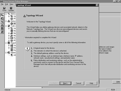
The first step is to add the outermost connection, in this case, the PIX Firewall. The easiest way to do this with a supported policy enforcement point is to use the network Topology Wizard. The initial network Topology Wizard screen is shown in Figure 8-7.
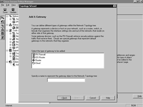
Select Next, and in the next screen, select the PIX Firewall object, as shown in Figure 8-8, and click Next once again to proceed to the next screen.
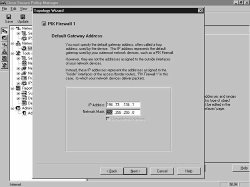
In this screen, shown in Figure 8-9, enter the default gateway address of the PIX. This is usually the direct ISP-provided connection to the Internet.
In the next screen, select to automatically discover the interfaces, as shown in Figure 8-10.
Figure 8-10. Network Topology Wizard—Device Definition Option Screen

In the next screen, enter the IP address over which the CSPM host will configure the device, along with the enable password. The Policy Distribution Host should also be selected here. These steps are shown in Figure 8-11. When finished, click the Discover button.
Figure 8-11. Network Topology Wizard—Device Connection and Policy Distribution Host Screen

As you can see in Figure 8-12, the network Topology Wizard has identified the firewall and all of the interfaces within it.

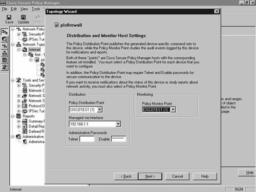
From the Topology Wizard screen shown in Figure 8-12, click Next until you reach the Distribution and Monitor Host Settings screen, as seen in Figure 8-13. Select the required host for both of these. Notice that the host is called CISCOTEST, but that there is a question mark by each name. You have yet to define the CSPM server as a network object.
Figure 8-13. Network Topology Wizard—Distribution and Monitor Host Settings Screen
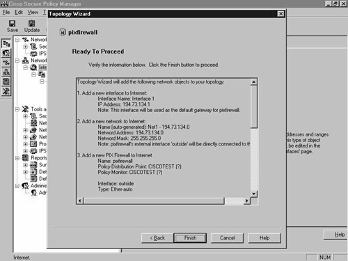
After configuration, you are ready to proceed. Figure 8-14 shows the screen that is presented. Click Finish to end the wizard.
The PIX Firewall network object has been added to the left pane of the Policy Manager window, as shown in Figure 8-15.
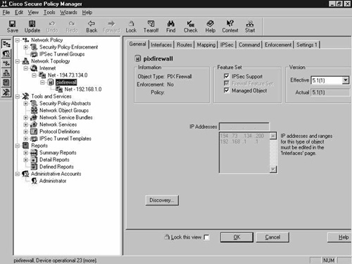
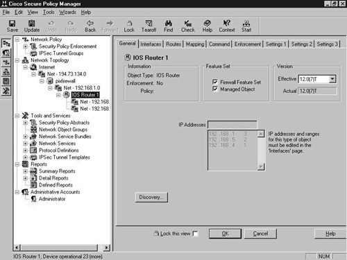
Figure 8-16 shows the Interfaces tab of the PIX Firewall network object. Note the correct network and IP addresses assigned to each interface. The PIX in question has four interfaces, and the two DMZ interfaces are disabled.

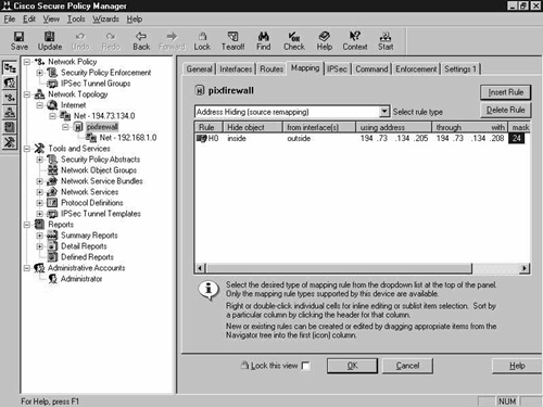
You will next have to manually configure NAT, which is configured on the Mapping tab of the PIX Firewall network object. Static translation is the same as the static command on the PIX, and address hiding is true NAT or Port Address Translation (PAT). Figure 8-17 shows the default empty Mapping tab screen.

Figure 8-18 shows this screen after you add an address-hiding mapping rule. Here you are hiding the inside interface from the outside interface, using the address range of 194.73.134.205 to 194.73.134.208 with a subnet mask of 255.255.255.0.
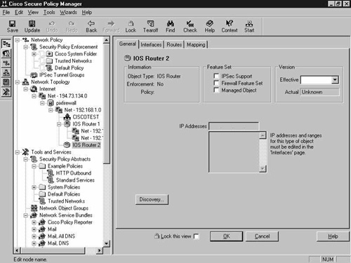
This completes the installation and initial configuration of the PIX Firewall. You are now going to enter the Cisco 2620 IOS router that is running the Cisco IOS Firewall. This device is going to be managed by CSPM; however, in this demonstration it has no real use. Configure the IOS router by using the network Topology Wizard as you did for the PIX Firewall. Figure 8-19 shows the result of adding the IOS router to the network topology.
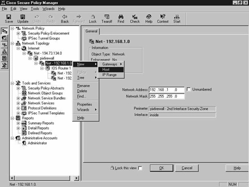
Next, add the CSPM server host to the network topology. This is pretty easy to do. Right-click the 192.168.1.0 network object and select New and then Host. Figure 8-20 shows this procedure.
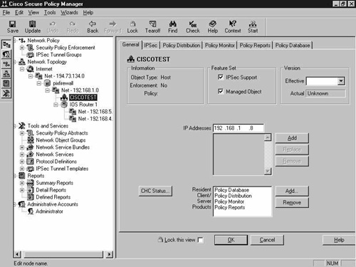
The CSPM administrator software is already aware of where it is running from, so the minute that you add the host to this network it presumes that this is the CSPM policy host. You are presented with a simple yes or no question. Clicking Yes will install this host as the CSPM server. This is shown in Figure 8-21.

Figure 8-22 shows the CSPM server added to the network topology. The host is available in the left pane.
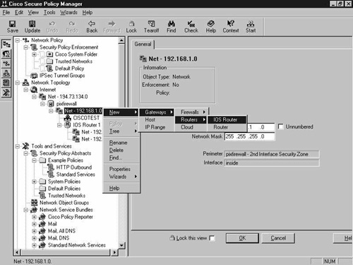
The final configuration step is to add the 2514 router and the 192.168.9.0 network. Remember, it is the 192.168.9.0 network where the clients reside, so this must be added to the network topology. This router has an interface in the 192.168.1.0 network, so right-click the 192.168.1.0 network and select New, Gateway, Routers, IOS Router. This is shown in Figure 8-23.
Because this is a manual installation, you are presented with blank configuration tabs, which you have to complete. Notice that there is no Commands tab, because this device is not managed by the CSPM. This is shown in Figure 8-24.
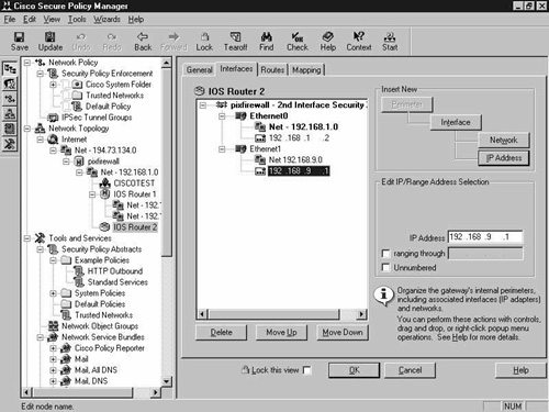
Click the Interfaces tab and configure the interfaces as addressed in the network topology diagram in Figure 8-5. The final result is shown in Figure 8-25.
The added router and the complete network topology can be clearly seen in Figure 8-26.

This completes the configuration of the network topology. Notice that the whole network has not been defined in the CSPM network topology. You have only defined the parts of the network that contain policy enforcement points and CSPM hosts.
The next step is to configure the security policy to enable your requirements to be implemented.
Configure the Security Policy
Once the network topology is configured, the next step is to configure the security policy. You are only concerned with the 192.168.9.0 network, so it is the only network or device for which you have to create a policy.
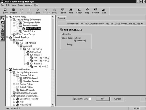
Start by dragging the 192.168.9.0 network object into the Security Policy Enforcement branch that is located at the top of the screen. Figure 8-27 shows this network object added to the branch.
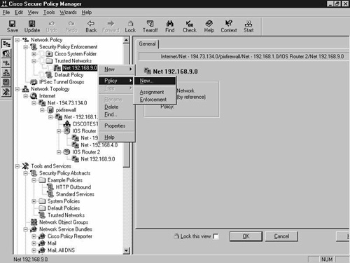
You can only assign policies to objects located within this branch. Right-click the object and select Policy, New, as shown in Figure 8-28.
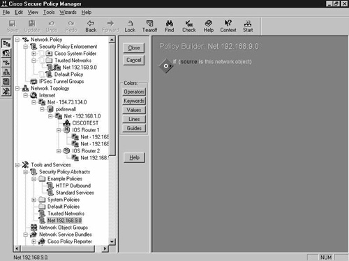
The blank policy with just the default If policy statement is displayed, as shown in Figure 8-29.
You need to build a policy that will allow the standard e-mail, Web, and DNS services to be passed to the Internet perimeter. Use the built-in policy tools to create a policy, as shown in Figure 8-30.
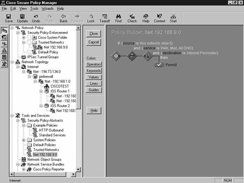
This policy will allow the 192.168.9.0 network access to the e-mail, Web, and DNS services through the Internet perimeter. This completes the creation of the system policy for the demonstration network.
Generate and Publish the Device-Specific Command Sets
After all of this configuration, you have to generate the device-specific command sets and publish them to the required managed policy enforcement points as configured in the Policy Manager software. The first step is to save and update the policy. This is shown in Figure 8-31.

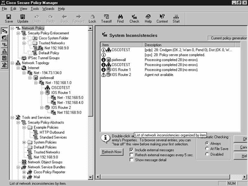
Saving and updating the policy generates the device-specific command sets that require distributing to the policy enforcement points. You can see in Figure 8-32 that the save and update operation completed successfully. If there are any inconsistencies with the distribution to the policy enforcement points, these would be displayed in Figure 8-32.
You are left with the task of deploying the device-specific command set to the appropriate devices. In this example, only the PIX Firewall command set will need updating. To do this, click the PIX Firewall object in the Network Topology section in the left pane. Select the Command tab, approve the command changes, and then click Approve Now in the bottom left corner to send the command changes to the device. Figure 8-33 shows this procedure.
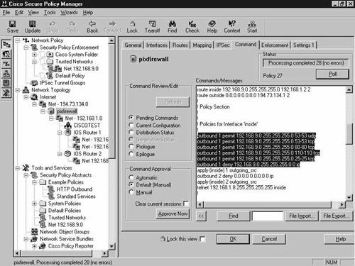
You can see the highlighted outbound commands that will allow the specified services. These were autogenerated after you created the security policy.