Chapter 14: Implementing Cisco Security Solutions
Throughout the course of this book, you have discovered the importance of cybersecurity operations and have gained skills in using various technologies to detect and analyze threats on an enterprise network. Now it's about time to take things to the next level by learning how to implement various security controls and technologies to prevent and mitigate cyber attacks.
Throughout the course of this chapter, you will learn how to implement various Cisco security solutions on a network to mitigate various types of threats and attacks. You will learn how to implement Authentication, Authorization, and Accounting (AAA), a zone-based firewall, and an Intrusion Prevention System (IPS) on an enterprise network.
In this chapter, we will cover the following topics:
- Implementing AAA in a Cisco environment
- Deploying a zone-based firewall
- Configuring an IPS
Let's dive in!
Technical requirements
To follow along with the exercises in this chapter, please ensure that you have Cisco Packet Tracer 7.3.1 or higher: https://www.netacad.com/courses/packet-tracer.
Link for Code in Action video: https://bit.ly/3aAXc7C
Implementing AAA in a Cisco environment
In this section, you will learn how to implement AAA within a Cisco environment. You will discover how to implement local AAA and server-based AAA using Remote Authentication Dial-In User Service (RADIUS) and Terminal Access Controller Access-Control System Plus (TACACS+) protocols on a Cisco Internetwork Operating System (IOS) router. The objective of this lab is to provide you with hands-on experience and skills in implementing AAA within an enterprise network.
Before you get started, go to the Cisco Networking Academy website to enroll in the Intro to Packet Tracer course at https://www.netacad.com/courses/packet-tracer. This free online course will teach you how to download and use the Cisco Packet Tracer application to its fullest potential. This is a mandatory requirement if you do not have prior experience with Cisco IOS devices and the Cisco Packet Tracer application.
Before building the lab environment, the following are a couple of important factors:
- In the lab topology, use Cisco 2911 routers and Cisco 2960 switches.
- Use straight-through cables to interconnect each device as shown in the network diagram.
Once the Cisco Packet Tracer application is installed on your computer, please build the following network topology for this lab exercise:

Figure 14.1 – AAA lab topology
Once you have connected each device as shown in the preceding figure, we'll be using the following IPv4 addressing scheme to configure the IP addresses on each device:

Figure 14.2 – IP addressing table
To get started with deploying the Zone-Based Policy Firewall (ZPF), use the instructions mentioned in the following sections.
Part 1 – Configuring IP addresses on host devices
- To configure the IP address on a host device such as the RADIUS server, select the Desktop tab | IP Configuration:

Figure 14.3 – IP configuration interface
- Ensure that you assign the appropriate IP address, subnet mask, and default gateway to the RADIUS server, TACACS+ server, PC 1, and PC 2 based on the IP addressing table.
Part 2 – Configuring RADIUS and TACACS+ services
- Select RADIUS Server, click on Services | AAA, and then enable the service, configuring it using the following parameters:
- Client Name: R2
- Client IP: 192.168.1.1
- Secret: radiuspassword
- ServerType: Radius
The following screenshot shows the parameters on the RADIUS server:

Figure 14.4 – Configuring RADIUS
- Create a username and password to authenticate the RADIUS client (R2) with the RADIUS server with the following parameters:
- Username: RemoteUser
- Password: CyberOps2
The following screenshot shows how the parameter needs to be configured:

Figure 14.5 – RADIUS client
- Next, select TACACS+ Server, click on Services | AAA, and then enable the service and use R3 as the TACACS client with the following parameters:
- Client Name: R3
- Client IP: 10.1.1.6
- Secret: tacacspassword
- ServerType: Tacacs
The following screenshot shows the parameters on the server:

Figure 14.6 – Configuring TACACS+
- Create a username and password to authenticate the TACACS+ client (R3) with the TACACS+ server. Use the following parameters for the TACACS+ client:
- Username: RemoteUser
- Password: CyberOps3
The following screenshot shows the parameters on the server:

Figure 14.7 – TACACS+ client
Part 3 – Configuring local AAA on the R1 router
- On R1, use the following commands to configure the hostname and a Message-of-the-Day (MOTD) banner and disable domain name lookup:
Router>enable
Router#configure terminal
Router(config)#hostname R1
R1(config)#banner motd %Keep Out!!!%
R1(config)#no ip domain-name lookup
- Next, configure the IP addresses on the interfaces of R1:
R1(config)#interface gigabitEthernet 0/1
R1(config-if)#description Connected to LAN
R1(config-if)#ip address 172.16.1.1 255.255.255.0
R1(config-if)#no shutdown
R1(config-if)#exit
R1(config)#interface gigabitEthernet 0/0
R1(config-if)#description Connected to R2
R1(config-if)#ip address 10.1.1.2 255.255.255.252
R1(config-if)#no shutdown
R1(config-if)#exit
- Enable OSPFv2 dynamic routing on R1:
R1(config)#router ospf 1
R1(config-router)#passive-interface gigabitEthernet 0/1
R1(config-router)#network 172.16.1.0 0.0.0.255 area 0
R1(config-router)#network 10.1.1.0 0.0.0.3 area 0
R1(config-router)#exit
- Secure the privilege exec mode of R1 and create a local database with a user account:
R1(config)#enable secret cisco123
R1(config)#username Admin1 secret password1
- Next, enable AAA on R1 and configure it to use the local database for login authentication:
R1(config)#aaa new-model
R1(config)#aaa authentication login default local
- Configure the console port to use the AAA default method list to authenticate users when logging on:
R1(config)#line console 0
R1(config-line)#login authentication default
R1(config-line)#exit
- Assign R1 to a domain and create asymmetric encryption keys for remote access using SSH:
R1(config)#ip domain-name ciscolab.local
R1(config)# crypto key generate rsa general-keys modulus 1024
- Next, create a named method list to authenticate SSH users on the R1 router:
R1(config)#aaa authentication login SSH-Auth local
- Configure the Virtual Terminal (VTY) lines to use the AAA SSH-Auth list when authenticating remote access users:
R1(config)#line vty 0 15
R1(config-line)#login authentication SSH-Auth
R1(config-line)#transport input ssh
R1(config-line)#exit
Part 4 – Configuring server-based AAA using RADIUS
- Configure the hostname for the R2 router using the hostname command.
- Configure the MOTD banner using the banner motd command.
- Disable domain lookup using the no ip domain-name lookup command.
- Configure each interface on the R2 router with the appropriate IP address and subnet mask as shown in the IP addressing table.
- Configure OSPFv2 dynamic routing on R2:
R1(config)#router ospf 1
R1(config-router)#passive-interface gigabitEthernet 0/1
R1(config-router)#network 192.168.1.0 0.0.0.255 area 0
R1(config-router)#network 10.1.1.0 0.0.0.3 area 0
R1(config-router)#network 10.1.1.4 0.0.0.3 area 0
R1(config-router)#exit
- Secure access to the privilege exec mode of the router and create a local database with the username Admin2:
R1(config)#enable secret cisco123
R1(config)#username Admin2 secret password2
- Configure R2 to use the RADIUS server IP address and the secret key for AAA:
R2(config)#radius-server host 192.168.1.100
R2(config)#radius-server key radiuspassword
- Enable AAA on R2 and configure all user authentication logins to use the RADIUS server:
R2(config)#aaa new-model
R2(config)#aaa authentication login default group radius local
- Configure the console interface to use the default AAA authentication method:
R2(config)#line console 0
R2(config-line)#login authentication default
R2(config-line)#exit
- Assign R2 to a domain and create asymmetric encryption keys for remote access using SSH:
R2(config)#ip domain-name ciscolab.local
R2(config)# crypto key generate rsa general-keys modulus 1024
- Configure the VTY lines to use the AAA default method list when authenticating remote access users:
R2(config)#line vty 0 15
R2(config-line)#login authentication default
R2(config-line)#exit
Part 5 – Configuring server-based AAA using TACACS+
- Configure the hostname for the R3 router using the hostname command.
- Configure the MOTD banner using the banner motd command.
- Disable domain lookup using the no ip domain-name lookup command.
- Configure each interface on the R3 router with the appropriate IP address and subnet mask as shown in the IP addressing table.
- Configure OSPFv2 dynamic routing on R3:
R3(config)#router ospf 1
R3(config-router)#passive-interface gigabitEthernet 0/1
R3(config-router)#network 172.17.1.0 0.0.0.255 area 0
R3(config-router)#network 10.1.1.4 0.0.0.3 area 0
R3(config-router)#exit
- Secure access to the privilege exec mode of the router and create a local database with the username Admin3:
R3(config)#enable secret cisco123
R3(config)#username Admin3 secret password3
- Configure R3 to use the TACACS+ server IP address and secret key for AAA:
R3(config)# tacacs-server host192.168.1.200
R3(config)# tacacs-server key tacacspassword
- Enable AAA on R3 and configure all user authentication logins to use the RADIUS server:
R3(config)#aaa new-model
R3(config)#aaa authentication login default group tacacs+ local
- Configure the console interface to use the default AAA authentication method:
R3(config)#line console 0
R3(config-line)#login authentication default
R3(config-line)#exit
- Assign R3 to a domain and create asymmetric encryption keys for remote access using SSH:
R3(config)#ip domain-name ciscolab.local
R3(config)# crypto key generate rsa general-keys modulus 1024
- Configure the VTY lines to use the AAA default method list when authenticating remote access users:
R3(config)#line vty 0 15
R3(config-line)#login authentication default
R3(config-line)#exit
Part 6 – Verification
- Click on PC1, select the Desktop tab, and then click on Telnet / SSH Client, as shown in the following screenshot:

Figure 14.8 – Telnet / SSH Client
- Next, set Connection Type as SSH, insert an IP address for any of the three routers and the SSH username, and then click Connect:

Figure 14.9 – SSH connection
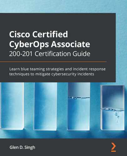
Remember that the router will use AAA as the primary method for user authentication, and only if the AAA service or server is not available will the router use the local database.
- Next, you will be prompted to enter the corresponding password for the user account, as shown:
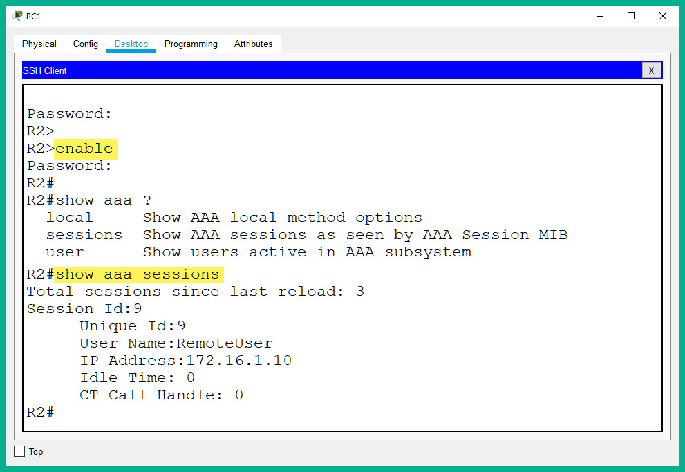
Figure 14.10 – Remote access
As shown in the preceding screenshot, logon to the router was successful. This validates that AAA was configured correctly. If AAA was not configured properly, the router will not be able to use the AAA server for authentication, which will result in using the account on the local database to log in to the device. Keep in mind that when entering the password on the terminal interface, Cisco IOS keeps it invisible as a security measure.
Having completed this lab, you have gained the skills and hands-on experience for implementing both local and server-based AAA for user authentication in a Cisco environment. In the next section, you will learn how to deploy a zone-based firewall on an enterprise network.
Deploying a zone-based firewall
In this section, you will learn how to implement a ZPF using a Cisco IOS router on a network. To get started with this exercise, we'll be using the Cisco Packet Tracer application. This application will allow us to create a simulated Cisco environment to practice our skills and gain experience.
The objective of this lab is to configure a Cisco IOS router as a ZPF. This will allow the ZPF to allow (permit) host devices on the internal network (inside zone) to access external devices (outside zone). However, it will restrict traffic that is originating from the outside zone that is attempting to access any resources within the inside zone.
Before building the lab environment, the following are a couple of important factors:
- In the lab topology, use Cisco 2911 routers and Cisco 2960 switches.
- Use straight-through cables to interconnect each device as shown in the network diagram.
Once the Cisco Packet Tracer application is installed on your computer, please build the following network topology for this lab exercise:
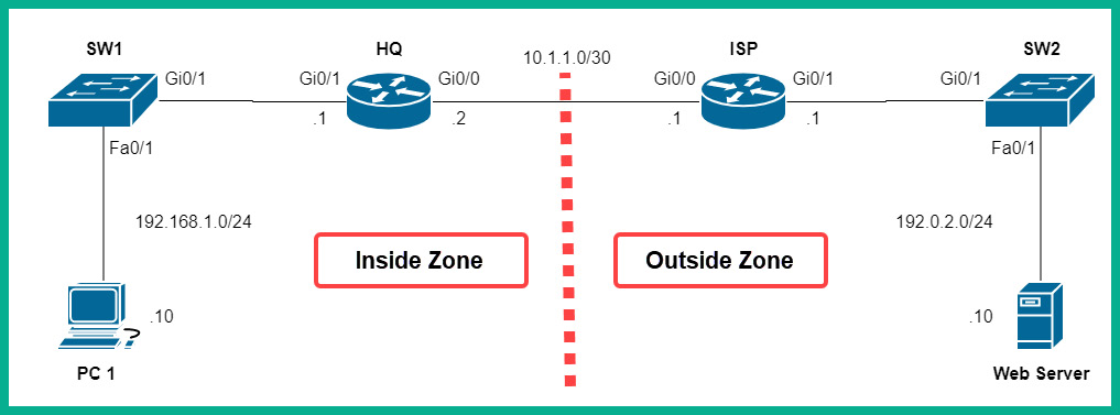
Figure 14.11 – Zone-based firewall lab topology
As shown in the preceding diagram, the corporate network is connected to the Gi0/0 interface of the HQ router, while the internet is connected to the Gi0/0 interface of the same HQ router.
Once you have connected each device as shown in the preceding figure, we'll be using the following IPv4 addressing scheme to configure the IP addresses on each device:

Figure 14.12 – IP addressing scheme
To get started with deploying the ZPF, use the instructions mentioned in the following sections.
Part 1 – Configuring IP addresses on PC 1 and the web server
Using the IP addressing table, configure the IP address, subnet mask, and default gateway on both PC 1 and the web server.
Part 2 – Enabling the security technology license on the HQ router
- Click on the HQ router, select the CLI tab, and then type no to prevent the initial configuration dialog from proceeding.
- Next, use the show version command to verify that the security technology license is not active:
Router>enable
Router#show version
The following screenshot shows that the security technology license is not active/missing:

Figure 14.13 – Checking the security technology license
- Use the following sequence of commands to activate the security technology license on HQ:
Router#configure terminal
Router(config)#license boot module c2900 technology-package securityk9
An end user license agreement will appear. Type yes and hit Enter to agree. Then, type exit to move back to privilege mode on the HQ router.
- Next, to ensure that the license becomes active, you will need to save the device's configurations and reboot the router. Use the following commands to complete this task:
Router#write
Router#copy running-config startup-config
Press Enter two times to save the configurations. Then, use the reload command to reboot the device:
Router#reload
- Once the device has been rebooted, use the show version command to verify that the license is active:
Router>enable
Router#show version
The following screenshot indicates that the security technology license is now active:

Figure 14.14 – Verifying the status of the security technology license
Part 3 – Configuring IP addresses and routes on HQ and ISP routers
- Use the following commands to configure the hostname on the HQ router:
Router>enable
Router#configure terminal
Router(config)#hostname HQ
- Next, use the following commands to assign both a description and the IP addresses to the interfaces of the HQ router:
HQ(config)#interface gigabitEthernet 0/0
HQ(config-if)#description Connected to ISP
HQ(config-if)#ip address 10.1.1.2 255.255.255.252
HQ(config-if)#no shutdown
HQ(config-if)#exit
HQ(config)#interface gigabitEthernet 0/1
HQ(config-if)#description Connected to LAN
HQ(config-if)#ip address 192.168.1.1 255.255.255.0
HQ(config-if)#no shutdown
HQ(config-if)#exit
- Create a default static route on HQ that points to the internet (ISP):
HQ(config)#ip route 0.0.0.0 0.0.0.0 10.1.1.1
- Use the following commands to configure the hostname on the ISP router:
Router>enable
Router#configure terminal
Router(config)#hostname ISP
- Next, use the following commands to assign both a description and the IP addresses to the interfaces of the ISP router:
ISP(config)#interface gigabitEthernet 0/0
ISP(config-if)#description Connected to HQ
ISP(config-if)#ip address 10.1.1.1 255.255.255.252
ISP(config-if)#no shutdown
ISP(config-if)#exit
ISP(config)#interface gigabitEthernet 0/1
ISP(config-if)#description Connected to Web Server
ISP(config-if)#ip address 192.0.2.1 255.255.255.0
ISP(config-if)#no shutdown
ISP(config-if)#exit
- Create a default static route on ISP that points to the HQ router:
ISP(config)#ip route 0.0.0.0 0.0.0.0 10.1.1.2
Part 4 – Creating security zones
On the HQ router, we will create two security zones, an inside zone that is assigned to the internal interface (gi0/1), and an outside zone that is assigned to the external interface (gi0/0):
- Use the following command to change the hostname of the router to HQ:
Router>enable
Router#configure terminal
Router(config)#hostname HQ
- Use the zone security command to create a zone, one for the inside zone and another for the outside zone:
HQ(config)#zone security Inside-Zone
HQ(config-sec-zone)#exit
HQ(config)#zone security Outside-Zone
HQ(config-sec-zone)#exit
Part 5 – Identifying traffic
- Configure the HQ router to identify traffic that is originating from the inside zone, that is, traffic from 192.168.1.0/24. To do this, we can create an extended Access Control List (ACL) with the name Internal-Traffic:
HQ(config)#ip access-list extended Internal-Traffic
HQ(config-ext-nacl)#permit ip 192.168.1.0 0.0.0.255 any
HQ(config-ext-nacl)#exit
- Next, create a class map with the name Internal-Class-Map on the HQ router to reference traffic that is permitted within our Internal-Traffic ACL:
HQ(config)#class-map type inspect match-all Internal-Class-Map
HQ(config-cmap)#match access-group name Internal-Traffic
HQ(config-cmap)#exit
Part 6 – Creating a policy map to define the action of matching traffic
Create a policy map with the name Inside-2-Outside, and then configure it to inspect and use the information from the Internal-Class-Map class map:
HQ(config)#policy-map type inspect Inside-2-Outside
HQ(config-pmap)#class type inspect Internal-Class-Map
HQ(config-pmap-c)#inspect
HQ(config-pmap-c)#exit
HQ(config-pmap)#exit
Part 7 – Identifying the zone pair and match policy
- Create a zone pair with the name Inside-2-Outside-ZonePair with the inside and outside zones:
HQ(config)#zone-pair security Inside-2-Outside-ZonePair source Inside-Zone destination Outside-Zone
- Next, assign the Inside-2-Outside policy map to the zone pair:
HQ(config-sec-zone-pair)#service-policy type inspect Inside-2-Outside
HQ(config-sec-zone-pair)#exit
Part 8 – Assigning the security zones to the interface
- Configure the internal interface as the inside zone:
HQ(config)#interface gigabitEthernet 0/1
HQ(config-if)#zone-member security Inside-Zone
HQ(config-if)#exit
- Configure the external interface as the outside zone:
HQ(config)#interface gigabitEthernet 0/0
HQ(config-if)#zone-member security Outside-Zone
HQ(config-if)#exit
Part 9 – Verification
- Click on PC1, select the Desktop tab and then Command Prompt, and ping the web server:

Figure 14.15 – Connectivity test
As shown in the preceding screenshot, PC1 on the inside zone is able to communicate with the web server on the outside zone.
- On the HQ router, use the show policy-map type inspect zone-pair sessions command to see any established sessions that are allowed through the ZPF:

Figure 14.16 – Viewing active sessions
The following information can be gathered from the preceding screenshot:
- The existing zone pairs: Inside-2-Outside-ZonePair
- The policy map: Inside-2-Outside
- The class map: Internal-Class-Map
- The ACL: Internal-Traffic
- The source IP address and port: 192.168.1.10:33
- The destination IP address and port: 192.0.2.10:0
- Protocol: ICMP
However, when you try to perform a ping test from the web server to PC1, the connection will fail. This is simply due to the ZPF policy to filter traffic originating from the outside zone to the inside zone, as shown:

Figure 14.17 – Testing the ZPF policy
Furthermore, you can use the following commands to troubleshoot ZPF configurations:
- show class-map: Displays the class map on the router
- show policy-map type inspect zone-pair sessions: Displays active session information
- show zone security: Displays the security zone security and its interfaces
- show zone-pair security: Displays zone pairs and the policy map
Having completed this lab, you have gained the hands-on experience and skills to implement a ZPF within a Cisco environment to filter traffic between networks. In the next section, you will learn how to configure a network-based IPS.
Configuring an IPS
In this section, you will learn how to implement an IPS on a Cisco IOS router to scan and filter inbound traffic to the corporate network. As with the previous hands-on exercises, we will be using the Cisco Packet Tracer application to simulate a Cisco environment.
Before building the lab environment, the following are a couple of important factors:
- In the lab topology, use Cisco 1941 routers and Cisco 2960 switches.
- Use straight-through cables to interconnect each device as shown in the network diagram.
Once the Cisco Packet Tracer application is installed on your computer, please build the following network topology for this lab exercise:

Figure 14.18 – Cisco IPS lab topology
As shown in the preceding diagram, the HQ router is connected to the 192.168.1.0/24 network, which represents an internal corporate network. The objective is to configure the HQ router to also function as an IPS to scan and filter inbound traffic that is originating from the ISP and the internet.
Once you have connected each device as shown in the preceding figure, we'll be using the following IPv4 addressing scheme to configure the IP addresses on each device:

Figure 14.19 – IP addressing table
To get started with configuring the IPS, use the following instructions.
Part 1 – Configuring IP addresses on end devices
- Configure all end devices, such as PC1, Syslog Server, and Internet User, with their corresponding IP addresses, subnet masks, and default gateways.
- Ensure that each end device is able to ping its default gateway.
- Enable the logging service on Syslog Server, click on the Services tab | SYSLOG, and then set Service to On:
Figure 14.20 – Enabling the logging service
Part 2 – Enabling the security technology license on the HQ router
- Click on the HQ router, select the CLI tab, and type no to prevent the initial configuration dialog from proceeding.
- Next, use the show version command to verify that the security technology license is not active:
Router>enable
Router#show version
The following screenshot shows that the security technology license is not active/missing:

Figure 14.21 – Checking the security technology license
- Use the following sequence of commands to activate the security technology license on HQ:
Router#configure terminal
Router(config)#license boot module c1900 technology-package securityk9
An end user license agreement will appear. Type yes and hit Enter to agree. Then, type exit to move back to privilege mode on the HQ router.
- Next, to ensure that the license becomes active, you will need to save the device's configurations and reboot the router. Use the following commands to complete this task:
Router#write
Router#copy running-config startup-config
Press Enter two times to save the configurations. Then, use the reload command to reboot the device:
Router#reload
- Once the device has been rebooted, use the show version command to verify that the license is active:
Router>enable
Router#show version
The following screenshot indicates that the security technology license is now active:

Figure 14.22 – Verifying the status of the security technology license
Part 4 – Configuring the IPS signature storage location and rule on HQ
- On the HQ router, use the mkdir command to create a directory within flash: to store the IPS signatures and rules:
Router#mkdir ciscoipsdir
Create directory filename [ipsdir]?
Created dir flash:ipsdir
When the router asks whether you want to accept the changes, simply hit Enter on your keyboard as an indication of yes.
- Next, use the ip ips config location command to configure the IPS signature storage location as our ciscoipsdir directory, as shown:
Router#configure terminal
Router(config)#ip ips config location flash:ciscoipsdir
- Use the ip ips name command to create a name for our IPS rule:
Router(config)#ip ips name ciscoipsrule
Router(config)#exit
Part 5 – Configuring the logging of IPS events
It's important to enable the logging of the IPS events on the HQ router whenever a security event occurs, hence we enabled the syslog feature on the syslog server at the beginning of this lab:
- Use the clock set command on the HQ router to manually configure the date and time on the device:
Router#clock set 10:45:00 18 february 2021
- Then, use the service timestamps log datetime msec command to configure the router to include the date and timestamps within each syslog message it generates:
Router#configure terminal
Router(config)#service timestamps log datetime msec
- Next, use the following commands to enable the logging of the IPS event and to send those syslog messages to the syslog server on our network:
Router(config)#ip ips notify log
Router(config)#logging host 192.168.1.20
Part 6 – Configuring IPS with signature categories
- Use the following sequence of commands to retire all the IPS signature categories by using the retired true command as shown:
Router(config)#ip ips signature-category
Router(config-ips-category)#category all
Router(config-ips-category-action)#retired true
Router(config-ips-category-action)#exit
- Use the category ios_ips basic command to unretire the IOS IPS Basic category of signatures:
Router(config-ips-category)#category ios_ips basic
Router(config-ips-category-action)#retired false
Router(config-ips-category-action)#exit
Router(config-ips-category)#exit
Do you want to accept these changes? [confirm]
When the router asks whether you want to accept the changes, simply hit Enter on your keyboard as an indication of yes.
Part 7 – Applying the IPS rule to an interface
Use the following commands to apply the IPS rule to inspect and filter traffic that is leaving the gigabitEthernet 0/1 interface on the HQ router:
Router(config)#interface gigabitEthernet 0/1
Router(config-if)#ip ips ciscoipsrule out
Router(config-if)#exit
Part 8 – Creating an alert and dropping inbound ICMP Echo Reply packets
- To enable the IPS signature to filter ICMO Echo Request messages, use the following commands:
Router(config)#ip ips signature-definition
Router(config-sigdef)#signature 2004 0
Router(config-sigdef-sig)#status
Router(config-sigdef-sig-status)#retired false
Router(config-sigdef-sig-status)#enabled true
Router(config-sigdef-sig-status)#exit
This configuration will block any ICMP Echo Request messages that are originating from outside the 192.168.1.0/24 network.
- Configure the IPS to create an alert for any event and deny (terminate) the inline messages:
Router(config-sigdef-sig)#engine
Router(config-sigdef-sig-engine)#event-action produce-alert
Router(config-sigdef-sig-engine)#event-action deny-packet-inline
Router(config-sigdef-sig-engine)#exit
Router(config-sigdef-sig)#exit
Router(config-sigdef)#exit
Router(config-sigdef-sig)# Do you want to accept these changes? [confirm]
When the router asks whether you want to accept the changes, simply hit Enter on your keyboard as an indication of yes.
Important note
To learn more about Cisco IPS Signature 2004, please refer to the following URL: https://tools.cisco.com/security/center/viewIpsSignature.x?signatureId=2004.
Part 3 – Configuring IP addresses and routes on HQ and ISP routers
- Use the following commands to configure the hostname on the HQ router:
Router>enable
Router#configure terminal
Router(config)#hostname HQ
- Next, use the following commands to assign both a description and the IP addresses to the interfaces of the HQ router:
HQ(config)#interface gigabitEthernet 0/0
HQ(config-if)#description Connected to ISP
HQ(config-if)#ip address 10.1.1.2 255.255.255.252
HQ(config-if)#no shutdown
HQ(config-if)#exit
HQ(config)#interface gigabitEthernet 0/1
HQ(config-if)#description Connected to LAN
HQ(config-if)#ip address 192.168.1.1 255.255.255.0
HQ(config-if)#no shutdown
HQ(config-if)#exit
- Create a default static route on HQ that points to the internet (ISP):
HQ(config)#ip route 0.0.0.0 0.0.0.0 10.1.1.1
HQ(config)#exit
- Use the following commands to configure the hostname on the ISP router:
Router>enable
Router#configure terminal
Router(config)#hostname ISP
- Next, use the following commands to assign both a description and the IP addresses to the interfaces of the ISP router:
ISP(config)#interface gigabitEthernet 0/0
ISP(config-if)#description Connected to HQ
ISP(config-if)#ip address 10.1.1.1 255.255.255.252
ISP(config-if)#no shutdown
ISP(config-if)#exit
ISP(config)#interface gigabitEthernet 0/1
ISP(config-if)#description Connected to Web Server
ISP(config-if)#ip address 192.0.2.1 255.255.255.0
ISP(config-if)#no shutdown
ISP(config-if)#exit
HQ(config)#exit
- Create a default static route on ISP that points to the HQ router:
ISP(config)#ip route 0.0.0.0 0.0.0.0 10.1.1.2
Part 9 – Verification
- Use the show ip ips all command on the HQ router for the IPS configurations on the device:

Figure 14.23 – Verifying IPS configurations
As shown in the preceding screenshot, the IPS storage location is set to flash:ciscoipsdir.
The following screenshot shows the events that are created through syslog; there's only one active signature, the IPS rule that we created earlier, and the IPS rule that is configured under the interface:

Figure 14.24 – Additional verification
- Perform a ping test from PC1 to the Internet User device to verify connectivity:

Figure 14.25 – Testing connectivity
As shown in the preceding screenshot, PC1 can successfully send ping messages outside the 192.168.1.0/24 network.
- Next, perform a ping test from the Internet User device to PC1 to verify whether the IPS is working as expected:

Figure 14.26 – Verifying that IPS is functioning
As shown in the preceding screenshot, devices that are outside the 192.168.1.0/24 network will not be able to send ping messages such as ICMP Echo Request packets. This action was configured to deny (terminate) inline packets that met the criteria.
- Check the HQ router. You will see that a syslog message is generated for each time the IPS rule was triggered:
*Feb 18, 10:57:07.5757: %IPS-4-SIGNATURE: Sig:2004 Subsig:0 Sev:25 [192.0.2.10 -> 192.168.1.10:0] RiskRating:25
*Feb 18, 10:57:13.5757: %IPS-4-SIGNATURE: Sig:2004 Subsig:0 Sev:25 [192.0.2.10 -> 192.168.1.10:0] RiskRating:25
Notice how each syslog message contains the timestamp and details pertaining to the security event. Additionally, these logs are sent to the syslog server on the network.
Having completed this exercise, you have gained hands-on skills on how to implement an IPS using a Cisco IOS router within a network. In the next section, you will discover how to implement various layer 2 security solutions.
Summary
During the course of this chapter, you have discovered how to implement various Cisco security technologies that use AAA to handle the authentication process when a user is attempting to log in to a network device. Additionally, you have gained hands-on experience of configuring a Cisco IOS router to function as a zone-based firewall to filter inbound traffic from an untrusted zone. Lastly, you have gained the skills for configuring an IPS to detect and block network-based intrusions.
I hope this chapter has been informative for you and will prove helpful in your journey toward learning the foundations of cybersecurity operations and gaining your Cisco Certified CyberOps Associate certification. In the next chapter, you will learn how to implement various security technologies within a Cisco environment.
Further reading
For more information on the topics covered in this chapter, refer to the following links:
- Configuring basic AAA: https://www.cisco.com/c/en/us/support/docs/security-vpn/terminal-access-controller-access-control-system-tacacs-/10384-security.html
- Zone-based policy firewall design: https://www.cisco.com/c/en/us/support/docs/security/ios-firewall/98628-zone-design-guide.html
- Cisco IOS IPS: https://www.cisco.com/c/en/us/td/docs/ios-xml/ios/sec_data_ios_ips/configuration/15-mt/sec-data-ios-ips-15-mt-book/sec-cfg-ips.html