The personal computer (PC) emerged as the most common desktop computer in the 1980s. Local–area networks (LANs) emerged as ways to network PCs in a common location. Networking technologies such as Token Ring and Ethernet allowed users to share disks and printers and exchange files with each other.
As originally defined, Ethernet and Token Ring provided network access to multiple devices on the same segment or ring. These LAN technologies had predefined limitations for how many devices could connect to a single segment, as well as for the physical distance between computers.
Desktop computers got faster, the number of computers grew, operating systems became multitasking (allowing multiple tasks to operate at the same time), and applications became more network–centric. All these advancements resulted in the congestion of LANs.
To address these issues, two device types emerged: repeaters and bridges. Repeaters are simple Open System Interconnection (OSI) Layer 1 devices that allow networks to extend beyond their defined physical distances. Bridges are OSI Layer 2 devices that physically split a segment into two and reduce the amount of traffic on either side of the bridge. This setup allows more devices to connect to the LAN and reduces congestion.
LAN switches emerged as a natural extension of bridging, revolutionizing the concept of local–area networking.
The term switching originally described devices that made packet–forwarding decisions in wide area networks (WANs). Today, LAN switching describes technologies that are an extension of traditional bridges.
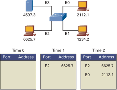
Bridges connect two or more LAN segments and make forwarding decisions on whether to transmit packets from one segment to another. When a packet arrives, the bridge inspects the destination and source Media Access Control (MAC) addresses in the packet. (This is an example of store–and–forward switching.) It places an entry in a table indicating that the source MAC address is located off the bridge interface in which the packet arrived. The bridge then consults the same table for an entry for the destination MAC address.
If it has an entry for the destination MAC address, and the entry indicates the MAC address is located on a different port from which the packet was received, the bridge forwards the packet onto the specified port.
If the bridge table indicates the destination MAC address is located off the interface for which it was received, then the bridge drops the packet. Why send it back onto the segment from which it came? This decision is where a bridge reduces congestion.
Finally, if the destination MAC address is not in the bridge’s table, then that indicates the bridge has not seen a packet destined to this MAC address. The bridge then forwards the packets out all other ports (called flooding) except the one in which the packet was received.
At their core, switches are multiport bridges. However, switches have radically matured into intelligent devices, replacing both bridges and hubs. Switches not only reduce traffic through the use of bridge tables, but also offer new functionality that support high–speed connections, virtual LANs (to be explained shortly), and even traditional routing.
Before the introduction of switches, the use of hubs and bridges improved Ethernet network performance. Multiple devices connected to a single Ethernet by connecting to Ethernet hubs. Hubs are Layer 1 devices that essentially provide two things: nondisruptive addition and removal of devices to an Ethernet and repeater functionality.
Ethernet, by specification, allows for multiple devices to connect to a single Ethernet. A device cannot transmit a packet if it is receiving traffic. This ability, called half–duplex, is similar to the idea that you can’t hear what someone is saying if you are talking. Two devices transmitting at the same time causes a collision. When a collision is detected, both devices back off and retransmit at random intervals.
Each Ethernet port on a switch, like a bridge, is a separate Ethernet, with its separate collision domain and its own bandwidth. Collisions on one switch port are not seen on other switch ports.
As switch Ethernet ports became less expensive, switches replaced hubs in the wiring closet. Initially, when switches were first introduced, network administrators plugged hubs (containing multiple hosts) into switch ports. But eventually, it became cost–effective to plug the hosts directly into a switch port. This arrangement gives each host its own dedicated Ethernet and removes the possibility of collisions. Because a dedicated switch connection has only two hosts (the switch and the host), you can configure an Ethernet switch port as full duplex, which means a device can both receive incoming traffic and transmit traffic simultaneously.
End stations have considerable more bandwidth when they use switches. Ethernet has the capability to run at multiple speeds: 10 Mbps, 100 Mbps, 1 Gbps, and 10 Gbps, and therefore switches can provide connectivity at these speeds.
However, network applications and the web create considerably more network traffic, re–introducing new forms of congestion problems. Switches can use quality of service (QoS) and other mechanisms to help the congestion issue.
A virtual LAN (VLAN) is a group of hosts or network devices that form a single broadcast domain. Layer 2 trunking protocols such as 802.1q and Inter–Switch Link (ISL) allow a VLAN to extend across multiple network devices, including routers and LAN switches.
VLANs group related users regardless of where their physical hosts connect to the network. You might group users according to their functional team or location. The goal is to group users into VLANs so their traffic stays within the VLAN. This grouping provides the following benefits:
Broadcast control
Security
Performance
Network management
Switches communicate with each other using a trunking protocol such as Cisco’s ISL or the public domain 802.1q. These trunking protocols preserve the VLAN identification associated with a packet so that VLANs can extend across multiple switches. Routers can also recognize trunking and route amongst the VLANs.
As switches established themselves in networks, vendors added increasing functionality. Switches can perform forwarding decisions based on traditional Layer 3 routing and can even make forwarding decisions based on Layer 4 and above. Switches can provide power to IP–based phones.
Even though switches can perform the functions of other higher–layer devices such as routers and content switches, you must still separate these functionalities to avoid single points of failure.
All in all, switches are the workhorse of networks, providing functionality across almost all layers of the OSI model reliably and quickly.


