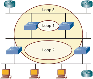
The Spanning Tree Protocol (STP) is a Layer 2 protocol designed to run on bridges and switches. The main purpose of spanning tree is to prevent loops from forming in a bridged network. The de-facto implementation of STP is based on the Institute of Electrical and Electronic Engineers (IEEE) 802.1d standard.
Loops form when redundant connections between switches form a circular path; the same packet travels endlessly around the same path in a circle. Multicast and broadcast packets are the culprits for bringing down networks when loops form because the packet is not destined to a single device, and no device is responsible for removing the packet from the network.
Loops can be deadly, bringing whole networks to a halt. Because of this possibility, it is always a good practice to break up Layer 2 networks with Layer 3 routers. Implementing Layer 2 redundancy in networks is sometimes necessary, and spanning tree ensures that loops do not form. With redundant Layer 2 links, only one path is active at a time. When the single path goes down, another path becomes active.
As with most networking technologies, there is a pendulum effect in the popularity of Layer 2 bridged (flat) networks versus Layer 3 routed networks. Cisco’s initial business convinced customers to insert routing devices to break up their predominately flat, bridged networks to more efficiently transmit traffic and reduce the number of users affected when broadcast storms and loops occurred. However, in the mid-1990s, LAN switches became wildly popular for replacing bridges and hubs. The “flat earth” craze went so far as to swing the pendulum back, with competitive sayings such as, “Switch if you can; route if you must.”
Once again, network administrators learned the consequences of building massive Layer 2 networks: one loop in the network could kill an entire network. Today, the role for switching and bridging is more clearly defined, and experience has shown that networks are more resilient and recover from failures more quickly when they use Layer 3 redundancy (such as HSRP) instead of Layer 2 (spanning tree).
New Internet standards improve the efficiency of STP:
802.1w Rapid Spanning Tree Protocol (RSTP)—. By default, traditional 802.1d STP treated every port the same concerning the time it took to transition into an active state. It took switch ports anywhere from 30–180 seconds to transition into a forwarding state, which was an eternity in computer time. 802.1w defines shortcuts based on what is connected to the switch port that allow quicker transition times.
802.1s Multiple Spanning Tree (MST)—. Switches that implement virtual local-area networks (VLANs) traditionally needed to run one spanning tree process per VLAN. Networks with hundreds of VLANs required each switch to have enough spanning-tree instances running to match one instance per VLAN. This setup is CPU-intensive on the switches and complicates recovery after a network event. 802.1s MST reduces the overall number of spanning-tree instances by mapping multiple VLANs with similar topologies to a single spanning-tree instance. MST improves traffic load-balancing and network-recovery time.
As previously mentioned, STP dynamically prevents loops in Layer 2 switched networks. STP defines a tree that spans all switches in a LAN by forcing certain redundant paths in the network into a blocked state. If a link that previously forwarded traffic becomes unavailable, STP dynamically reconfigures the network to redirect traffic flow by activating the appropriate standby path.
Switches dynamically determine the state of the spanning tree by exchanging information with others using bridge protocol data units (BPDUs). These packets contain information on each switch’s view of the network. The absence of a regularly scheduled BPDU from a neighbor switch indicates that that switch has disappeared.
The first order of business with spanning tree is for all of the switches in the spanning tree to elect a root. The root serves as the focal point for the rest of the switched network. Once the root is elected, each switch’s proximity to the root determines all forwarding and blocking decisions. Switches dynamically determine the root through the exchange of BPDUs containing root IDs. When determining the winner, smaller is better. If the root ID on Switch A is lower than that of Switch B, then Switch A becomes the root.
Traditionally, each VLAN on a switch had to have its own root, which could add considerable overhead to switches with a lot of VLANs. You can implement 802.1s MST to resolve this issue.
After a root is elected, switches implement the following rules for traditional 802.1d STP:
All ports on the root switch must be in a forwarding state.
After a switch determines that it is not root, it must identify the port that is closest to the root (called the root port) and put it in a forwarding state.
When multiple nonroot switches occupy a common segment, they must determine which switch has the shortest path to the root (called the designated port) and put it in a forwarding state.
All other ports connected to another switch or bridge must be in a blocking state. This arrangement is how STP prevents loops.
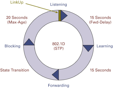
When a port first becomes active (for example, when a switch boots up), 802.1d STP requires that the port not forward traffic until the switch has had time to determine the state of the rest of the spanning tree. Specifically, a port must transition through the following states:
Listening/Blocking—. The port is blocked. However, the switch transmits and receives BPDUs to determine the state of the spanning tree. This state lasts 15 seconds by default.
Learning—. The port remains blocked and continues receiving and transmitting BPDUs. However, it also receives traffic and begins building a bridge table based on the source Media Access Control (MAC) addresses of the traffic it receives. This state lasts 15 seconds by default.
Forwarding—. If the switch determines that a port does not need to be blocked, it may begin forwarding traffic.
This process ensures that loops do not form when there is a topology change. However, if a failure occurs, all switches must go through the three states in the list. It takes at least 30 seconds for each switch to begin forwarding again. As far as network availability, this delay is generally too long for a recovery to occur.
Both proprietary and public-domain methods reduce the transition from blocking to forwarding. 802.1s, as mentioned earlier, enables specific types of switch ports to transition instantaneously, or near so. Basically, these shortcuts require careful planning: If a switch port is configured to expect a PC connected to it, and another switch is connected to the port instead, catastrophic temporary loops can form.
Spanning tree is an elegant solution for networks to automatically adjust to topology changes.


