Addressing
IPv6 addresses are four times the size of IPv4 addresses. The representation of IPv6 addresses is also very different. This section covers the new representations, syntaxes, and compressed forms of IPv6 addresses.
Representation of IPv6 Addresses
As defined in RFC 2373, IP Version 6 Addressing Architecture, three formats represent IPv6 addresses. The preferred format is the longest method. It represents all 32 hexadecimal characters that form an IPv6 address. The preferred format may also be seen as the representation that matches a computer's “thinking.”
The next method is the compressed representation of an IPv6 address. To simplify the typing of IPv6 addresses by humans, it is possible to compress the address when zero values are present in the IPv6 address. This means that preferred and compressed formats are different representations of the same IPv6 addresses, a new concept in comparison with IPv4.
Finally, the third method to represent an address is related to transition mechanisms where an IPv4 address is embedded in an IPv6 address. This last representation is less important than the preferred and the compressed format, because it is useful only if you're using specific transition mechanisms such as automatic IPv4-compatible tunnels and dynamic Network Address Translation Protocol Translation (NAT-PT). Automatic IPv4-compatible tunnels and dynamic NAT-PT mechanisms are discussed in detail in Chapter 5, “IPv6 Integration and Coexistence Strategies.”
Preferred IPv6 Address Representation
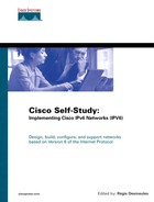
As shown in Figure 2-9, the preferred representation, also known as the complete form of an IPv6 address, has a series of eight 16-bit hexadecimal fields separated by colons (:). Each 16-bit field is textually represented by four hexadecimal characters, meaning that the value of each 16-bit field may have hexadecimal values 0x0000 through 0xFFFF. Alphanumeric characters used in hexadecimal are case-insensitive.
Figure 2-9. IPv6 Addresses Have Eight Fields of 16-Bit Hexadecimal Values Separated by Colons

The preferred format is the longest representation of an IPv6 address. A total of 32 hexadecimal characters may be represented in this preferred form (eight fields of four hexadecimal characters). In comparison, an IPv4 address has four 8-bit decimal fields separated by dots (.) for a possible total of 12 decimal characters.
Table 2-2 shows examples of IPv6 addresses in the preferred representation.
| Preferred Format of IPv6 Addresses |
|---|
| 0000:0000:0000:0000:0000:0000:0000:0000 |
| 0000:0000:0000:0000:0000:0000:0000:0001 |
| 2001:0410:0000:1234:FB00:1400:5000:45FF |
| 3ffe:0000:0000:0000:1010:2a2a:0000:0001 |
| 3FFE:0B00:0C18:0001:0000:1234:AB34:0002 |
| FE80:0000:0000:0000:0000:0000:0000:0009 |
| FFFF:FFFF:FFFF:FFFF:FFFF:FFFF:FFFF:FFFF |
Compressed Representation
In IPv6, it is common to use addresses that contain long strings of 0s. To make writing addresses containing 0 bits easier for humans, a special syntax compresses consecutive 0 values in two situations—successive 16-bit fields made of 0s and leading 0s in 16-bit fields of an IPv6 address.
Successive 16-Bit Fields Made up of 0s
To simplify the length of an IPv6 address when one to multiple successive 16-bit fields of 0 characters are present, it is legal to represent these fields of 0s as :: (a double colon). However, only one :: is permitted in an IPv6 address. This method makes many IPv6 addresses very small. The compressed representation of an IPv6 address also means that the same address can have several representations.
NOTE
When the :: is present in an IPv6 address, an address parser can identify the number of missing 0s. Then, the parser fills 0 characters between the two parts of the address until the 128-bit address is complete. If more than one :: is present in a compressed IPv6 address, there is no way for the parser to identify the size of each field of 0s. Therefore, only one :: is permitted per IPv6 address.
Table 2-3 presents examples of IPv6 addresses in the preferred format that have been compressed because they have one or more successive 16-bit fields of 0 characters. Bold characters in the preferred format addresses represent values to be removed to compress the addresses.
| Preferred Format | Compressed Format Using :: |
|---|---|
| 0000:0000:0000:0000:0000:0000:0000:0000 | :: |
| 0000:0000:0000:0000:0000:0000:0000:0001 | ::0001 |
| 2001:0410:0000:1234:FB00:1400:5000:45FF | 2001:0410::1234:FB00:1400:5000:45FF |
| 3ffe:0000:0000:0000:1010:2a2a:0000:0001 | 3ffe::1010:2a2a:0000:0001 |
| 3FFE:0B00:0C18:0001:0000:1234:AB34:0002 | 3FFE:0B00:0C18:0001::1234:AB34:0002 |
| FE80:0000:0000:0000:0000:0000:0000:0009 | FE80::0009 |
| FFFF:FFFF:FFFF:FFFF:FFFF:FFFF:FFFF:FFFF | FFFF:FFFF:FFFF:FFFF:FFFF:FFFF:FFFF:FFFF |
The address FFFF:FFFF:FFFF:FFFF:FFFF:FFFF:FFFF:FFFF is an example of an address in which all bits are set to 1. Therefore, this address cannot be compressed. Compressed form using the :: is available only when multiple successive 16-bit fields of 0 characters are present.
Table 2-4 presents illegal examples of compressed addresses. The compressed addresses represented use the :: more than once, which is an illegal IPv6 compressed address representation.
| Preferred Format | Compressed Format Using :: |
|---|---|
| 0000:0000:AAAA:0000:0000:0000:0000:0001 | ::AAAA::0001 |
| 3ffe:0000:0000:0000:1010:2a2a:0000:0001 | 3ffe::1010:2a2a::0001 |
Leading 0s in 16-Bit Fields of an IPv6 Address
The second method to compress addresses is applicable to each 16-bit hexadecimal field of an IPv6 address when one or more leading 0s are present. Leading 0s of each field can simply be removed to simplify the length of an IPv6 address. However, if every hexadecimal character of a 16-bit field is set to 0, at least one 0 character must be kept. Table 2-5 shows examples of addresses compressed when leading 0s are present. In these examples, all leading 0s of each 16-bit field are removed and all the following values are kept. Bold characters in the preferred format addresses represent values to be removed to compress the addresses.
| Preferred Format | Compressed Format |
|---|---|
| 0000:0000:0000:0000:0000:0000:0000:0000 | 0:0:0:0:0:0:0:0 |
| 0000:0000:0000:0000:0000:0000:0000:0001 | 0:0:0:0:0:0:0:1 |
| 2001:0410:0000:1234:FB00:1400:5000:45FF | 2001:410:0:1234:FB00:1400:5000:45FF |
| 3ffe:0000:0000:0000:1010:2a2a:0000:0001 | 3ffe:0:0:0:1010:2a2a:0:1 |
| 3FFE:0B00:0C18:0001:0000:1234:AB34:0002 | 3FFE:B00:C18:1:0:1234:AB34:2 |
| FE80:0000:0000:0000:0000:0000:0000:0009 | FE80:0:0:0:0:0:0:9 |
| FFFF:FFFF:FFFF:FFFF:FFFF:FFFF:FFFF:FFFF | FFFF:FFFF:FFFF:FFFF:FFFF:FFFF:FFFF:FFFF |
Combining Both Compression Methods
Compression of successive 16-bit fields made of 0 characters and compression of leading 0 characters within 16-bit fields can be mixed to simplify the length of IPv6 addresses. Table 2-6 presents examples in which both compression methods are applied. Bold characters in the preferred format addresses represent values to be removed to compress the addresses.
| Preferred Format | Compressed Format |
|---|---|
| 0000:0000:0000:0000:0000:0000:0000:0000 | :: |
| 0000:0000:0000:0000:0000:0000:0000:0001 | ::1 |
| 2001:0410:0000:1234:FB00:1400:5000:45FF | 2001:410::1234:FB00:1400:5000:45FF |
| 3ffe:0000:0000:0000:1010:2a2a:0000:0001 | 3ffe::1010:2a2a:0:1 |
| 3FFE:0B00:0C18:0001:0000:1234:AB34:0002 | 3FFE:B00:C18:1::1234:AB34:2 |
| FE80:0000:0000:0000:0000:0000:0000:0009 | FE80::9 |
IPv6 Address with an Embedded IPv4 Address
The third representation of an IPv6 address is to use an embedded IPv4 address within the IPv6 address.
The first part of the IPv6 address uses the hexadecimal representation, and the IPv4 address part is in decimal format. This is a specific representation of an IPv6 address used by transition mechanisms.
NOTE
The low-order 32-bit of the address may also be represented in hexadecimal on the implementation supporting the automatic IPv4-compatible tunnel mechanism. Thus, the decimal values are converted into hex.
NOTE
As mentioned at the beginning of this section, this form of IPv6 address is used by only two transition mechanisms. The transition mechanisms using this format are supported in the Cisco IOS Software technology, but the automatic IPv4-compatible tunnel mechanism is being deprecated in favor of more-efficient mechanisms. However, the transition mechanism called dynamic NAT-PT still embeds an IPv4 address within an IPv6 address for its operation. Thus, it uses this form of address.
Figure 2-10 shows the format of an IPv6 address using an embedded IPv4 address. This kind of address is made up of six high-order fields of 16-bit hexadecimal values, represented by X characters, followed by four low-order fields of 8-bit decimal values (IPv4 address), represented by d characters (for a total of 32 bits).
Figure 2-10. IPv6 Address with an Embedded IPv4 Address

Two kinds of IPv6 addresses have an embedded IPv4 address:
IPv4-compatible IPv6 address— Used to establish an automatic tunnel to carry IPv6 packets over IPv4 networks. This address is related to a transition mechanism of the IPv6 protocol.
IPv4-mapped IPv6 address— Used only on the local scope of nodes having both IPv4 and IPv6 stacks. Nodes use IPv4-mapped IPv6 addresses internally only. These addresses are never known outside the node itself and should not go on the wire as IPv6 addresses.
Although they both use the same address representation of an IPv4 address embedded in an IPv6 address, a different IPv6 prefix is defined for each kind of embedded IPv4 address. The IPv6 prefix for the IPv4-compatible IPv6 address is represented by the high-order 96-bit set to 0 followed by the 32-bit of the IPv4 address. The prefix for the IPv4-mapped IPv6 address is represented by the high-order 80-bit set to 0, then the next 16-bit set to 1, and finally followed by the 32-bit of the IPv4 address of the local node. The next section presents in detail the format of the IPv6 address with an embedded an IPv4 address.
Table 2-7 shows examples of each kind of IPv4 address embedded in IPv6 addresses and also demonstrates that both addresses can be represented in compressed format. The first address presented is the IPv4-compatible IPv6 address and the second is an IPv4-mapped IPv6 address. Bold characters in the preferred format addresses represent values to be removed to compress the addresses.
| Preferred Format | Compressed Format |
|---|---|
| 0000:0000:0000:0000:0000:0000:206.123.31.2 | 0:0:0:0:0:0:206.123.31.2 or ::206.123.31.2 |
| 0000:0000:0000:0000:0000:0000:ce7b:1f01 | 0:0:0:0:0:0:ce7b:1f01 or ::ce7b:1f01 |
| 0000:0000:0000:0000:0000:FFFF:206.123.31.2 | 0:0:0:0:0:FFFF:206.123.31.2 or ::FFFF:206.123.31.2 |
| 0000:0000:0000:0000:0000:FFFF:ce7b:1f01 | 0:0:0:0:0:FFFF:ce7b:1f01 or ::FFFF:ce7b:1f01 |
NOTE
Although the dynamic NAT-PT mechanism is based on the IPv4-compatible IPv6 address format, it does not use the IPv6 prefix presented here. Refer to Chapter 5 for more details about the prefix used by the dynamic NAT-PT mechanism.
IPv6 Address Representation for URL
In Uniform Resource Locator (URL) format, the colon (:) character is already defined to specify an optional port number. Here are examples of URLs using the colon character to specify a port number:
www.example.net:8080/index.html
https://www.example.com:8443/abc.html
In IPv6, the URL parser of Internet browsers must be able to differentiate between the colon of a port number and the colon in an IPv6 address. However, this is impossible because the compressed representation of an IPv6 address may include the double colon anywhere in the IPv6 address.
Therefore, to identify the IPv6 address while still keeping the colon character for URL format (port number), the IPv6 address must be enclosed in brackets, as defined in RFC 2732, Format for Literal IPv6 Addresses in URL's. Then, after the brackets, the port number may be added, followed by the directory and filename. Here are examples of URLs with IPv6 addresses between brackets:
[3ffe:b80:c18:1::50]:8080/index.html
https://[2001:410:0:1:250:fcee:e450:33ab]:8443/abc.html
However, using IPv6 addresses inside brackets should normally be used for diagnostic purposes only or when the naming service (DNS) is unavailable. Because IPv6 addresses are longer than IPv4 addresses, users tend to use the DNS and the fully qualified domain name (FQDN) format instead of the IPv6 address in hexadecimal representation.
IPv6 and Subnetting
In IPv4, there are two ways to represent a network prefix:
Decimal representation— A network mask is specified in d.d.d.d format. The network mask value represents the number of consecutive bits in binary that are set to 1.
Classless interdomain routing (CIDR) notation— The network prefix mask may also be specified with a decimal number representing the number of consecutive bits in binary set to 1. The slash character is used between the prefix and the network mask value.
Both representations mean the same number of network mask bits for nodes. For example, the network prefix 192.168.1.0 with the network mask value of 255.255.255.0 is the same as 192.168.1.0/24 in CIDR notation. The range of IP addresses available for nodes in this network varies from 192.168.1.1 to 192.168.1.254.
In IPv6, the network mask representation using the long form, such as d.d.d.d, is gone because of the new length of the IPv6 address. The only acceptable form to represent a network mask in IPv6 is CIDR notation. Although IPv6 addresses are in hexadecimal format, the network mask value is still a decimal value. Table 2-8 shows examples of IPv6 addresses and network prefixes using the network value in CIDR notation.
| IPv6 Prefix | Description |
|---|---|
| 2001:410:0:1:0:0:0:45FF/128 | Represents a subnet with only one IPv6 address. |
| 2001:410:0:1::/64 | Network prefix 2001:410:0:1::/64 can handle 264 nodes. This is the default prefix length for a subnet. |
| 2001:410:0::/48 | Network prefix 2001:410:0::/48 can handle 216 network prefixes of 64-bit. This is the default prefix length for a site. |
For both IPv4 and IPv6, the number of bits set to 1 in the network mask defines the length of the network prefix; the remaining part is for node addressing. This information is fundamental to IP. It tells each node when packets must be sent to the default router or to a specific node on the same link-layer subnet.
Another difference in IPv6 is the absence of reserved addresses in a network prefix range. In IPv4, the first and last addresses of the prefix range are reserved addresses. A range's first address is the network address and the last one is the broadcast address. This means that the total number of IPv4 addresses available in a range equals n2–2, where n is the number of bits for the host addressing. For example, with the network prefix 192.168.1.0/24, addresses 192.168.1.0 and 192.168.1.255 must not be assigned to nodes because they are reserved. In IPv4, it is also common to use different network mask values within a site. One subnet can use a network mask value, and the next subnet may use a different value.
IPv6 has no broadcast or network reserved addresses. Moreover, the number of bits for node addressing within a site prefix (48-bit) in IPv6 is so large that it is not necessary to make an addressing plan for a site using different network mask values. Therefore, network mask calculation for each subnet and the use of Variable-Length Subnet Masks (VLSMs) are not required. In IPv6, the subnetting allocation is much simpler than in IPv4.
IPv6 Address Types
Independent of representation and subnetting, different kinds of addresses are defined for IPv6, as described in RFC 2373, IP Version 6 Addressing Architecture. This section presents the types of IPv6 addresses defined in the protocol. In IPv6, addresses are assigned to network interfaces, not to nodes. Moreover, each interface owns and uses multiple IPv6 addresses simultaneously.
As shown in Figure 2-11, the three types of addresses are unicast, anycast, and multicast. Under the scope of each kind of address are one or more types of addresses. Unicast has link-local, site-local, aggregatable global, loopback, unspecified, and IPv4-compatible addresses. Anycast has aggregatable global, site-local, and link-local. Multicast has assigned and solicited-node. Specific scopes of IPv6's 128-bit addressing scheme are already assigned to each type of address.

Link-Local Address
IPv6 introduces scoped unicast addresses, which can be used only in a restricted context. The unicast link-local address is scoped and is used only between nodes connected on the same local link. The link-local address is used by several IPv6 mechanisms, such as Neighbor Discovery Protocol (NDP), described in detail in Chapter 3.
When an IPv6 stack is enabled on a node, one link-local address is automatically assigned to each interface of the node at boot time. As shown in Figure 2-12, the IPv6 link-local prefix FE80::/10 is used and the interface identifier in Extended Unique Identifier 64 (EUI-64) format is appended as the address's low-order 64-bit. Bits 11 through 64 are set to 0 (54-bit). Link-local addresses are only for local-link scope and must never be routed between subnets within a site.
Figure 2-12. Link-Local Address

NOTE
The IEEE defined an extended unique identifier based on 64-bit—EUI-64. EUI-64 format is a combination of the public 24-bit manufacturer ID assigned by the IEEE and a 40-bit value assigned by the manufacturer to its products. EUI-64 is related to the interface link-layer address. This chapter provides detailed information about the conversion of a link-layer address into EUI-64 format.
Because the low-order 64-bit of the link-local address is the interface identifier itself, the length of the link-local prefix is based on a 64-bit length (/64).
As shown in Table 2-9, the link-local address is represented by the IPv6 prefix FE80:0000:0000:0000:0000:0000:0000:0000/10 in the preferred format and by FE80::/10 in the compressed representation.
| Representation | Value |
|---|---|
| Preferred format | FE80:0000:0000:0000:0000:0000:0000:0000/10 |
| Compressed format[1] | FE80:0:0:0:0:0:0:0:0/10 |
| Compressed format | FE80::/10 |
| Binary format | High-order 10-bit is set to 1111 1110 10 |
[1] This is an intermediary compressed representation of the same address. This address is valid, but the shortened format of an IPv6 address should be used.
In IPv6, a node having an aggregatable global unicast address on a local link uses the link-local address of its default IPv6 router rather than the router's aggregatable global unicast address. If network renumbering must occur, meaning that the unicast aggregatable global prefix is changed to a new one, the default router can always be reached using the link-local address. Link-local addresses of nodes and routers do not change during network renumbering. Chapter 3 presents an example of prefix renumbering on a local link.
Site-Local Address
A site-local address is another unicast scoped address to be used only within a site. Site-local addresses are not enabled by default on nodes like link-local addresses, meaning that they must be assigned.
A site-local address is similar to private address spaces in IPv4, such as 10.0.0.0/8, 172.16.0.0/12, and 192.168.0.0/16, as defined in RFC 1918, Address Allocation for Private Internets. Site-local addresses may be used by any organization that has not received aggregatable global unicast IPv6 spaces from a provider. A site-local prefix and address may be assigned to any nodes and routers within a site. However, site-local addresses must never be routed on the global IPv6 Internet.
NOTE
Although site-local addresses are similar to the private addressing in IPv4, Network Address Translation (NAT) with IPv6 is undesirable between IPv6-only networks. Huge numbers of IPv6 addresses are available within the IPv6 address space to preserve the end-to-end model of the IP protocol.
As shown in Figure 2-13, the site-local address consists of the prefix FEC0::/10, a 54-bit field called Subnet-ID, and an interface identifier in EUI-64 format used as the low-order 64-bit.
Figure 2-13. Site-Local Address

The 54-bit Subnet-ID is available for site subnetting. This field allows a site to create up to 254 different IPv6 subnets (/64 prefix). Each subnet can use a different IPv6 prefix.
NOTE
The old Subnet-ID length for site-local addresses was based on 16-bit, allowing a site to create up to 65,535 different IPv6 subnets.
For example, a site with ten subnets may assign site-local prefixes such as the following:
Subnet 1— FEC0:0:0:0001::/64
Subnet 2— FEC0:0:0:0002::/64
Subnet 3— FEC0:0:0:0003::/64
Subnet 4— FEC0:0:0:0004::/64
Subnet 5— FEC0:0:0:0005::/64
Subnet 6— FEC0:0:0:0006::/64
Subnet 7— FEC0:0:0:0007::/64
Subnet 8— FEC0:0:0:0008::/64
Subnet 9— FEC0:0:0:0009::/64
Subnet 10— FEC0:0:0:000A::/64
As shown in Table 2-10, the site-local address is represented by the IPv6 prefix FEC0:0000:0000:0000:0000:0000:0000:0000/10 in the preferred format and by FEC0::/10 in the compressed representation.
| Representation | Value |
|---|---|
| Preferred format | FEC0:0000:0000:0000:0000:0000:0000:0000/10 |
| Compressed format[1] | FEC0:0:0:0:0:0:0:0/10 |
| Compressed format | FEC0::/10 |
| Binary format | High-order 10-bit is set to 1111 1110 11 |
[1] This is an intermediary compressed representation of the same address. This address is valid, but the shortened format of an IPv6 address should be used.
Site-local addresses are designed for devices that will never communicate with the global IPv6 Internet. Site-local addresses may have the following uses within a site:
Printers
Intranet servers
Network switches, bridges, gateways, wireless access points, and so on
Any servers and routers that must only be reached internally for management purposes
For now, site-local addresses are recommended to organizations that have plans to deploy the IPv6 protocol on their networks before getting aggregatable global unicast IPv6 spaces from providers. Site-local addressing is also recommended for experimental scenarios of network renumbering.
It is important to note that an IPv6 node may have several unicast IPv6 addresses, so site-local addresses can be used at the same time as aggregatable global unicast addresses. In this case, DNS is the tie-breaker. Moreover, it is expected that the site will use the same subnet ID for the site-local and aggregatable global unicast prefixes.
Aggregatable Global Unicast Address
Aggregatable global unicast addresses are IPv6 addresses used for the generic IPv6 traffic on the IPv6 Internet. Aggregatable global unicast addresses are similar to the unicast addresses used to communicate across the IPv4 Internet.
Aggregatable global unicast addresses represent the most important part of the IPv6 addressing architecture. The structure of aggregatable global unicast enables a strict aggregation of routing prefixes to limit the size of the global Internet routing table.
Each aggregatable global unicast IPv6 address has three parts:
Prefix received from a provider— The prefix assigned to an organization (leaf site) by a provider should be at least a /48 prefix, as recommended in RFC 3177, IAB/IESG Recommendations on IPv6 Address Allocations to Sites. The /48 prefix represents the high-order 48-bit of the network prefix. Moreover, the prefix assigned to the organization is part of the provider's prefix.
Site— With one /48 prefix allocated to an organization by a provider, it is possible for that organization to enable up to 65,535 subnets (assignment of 64-bit's prefix to subnets). The organization can use bits 49 to 64 (16-bit) of the prefix received for subnetting.
Host— The host part uses each node's interface identifier. This part of the IPv6 address, which represents the address's low-order 64-bit, is called the interface ID.
As shown in Figure 2-14, the prefix 2001:0410:0110::/48 is assigned by a provider to an organization. Then, within this organization, the prefix 2001:0410:0110:0002::/64 is enabled on a network subnet. Finally, a node on this subnet owns the IPv6 address 2001:0410:0110:0002:0200:CBCF:1234:4402.
Figure 2-14. Aggregatable Global Unicast Address

This is a simple example of an aggregatable global unicast prefix assigned to a leaf site by a provider. Chapter 7, “Connecting to the IPv6 Internet,” provides detailed information about aggregatable global unicast assignments between multiple sites, providers, and leaf sites.
IANA Assignments of Aggregatable Global Unicast Prefixes
The IANA assigned one IPv6 address prefix range in the whole IPv6 addressing space for aggregatable global unicast addresses. As shown in Table 2-11, this aggregatable global unicast address space is characterized by the IPv6 prefix 2000::/3.
| Representation | Values |
|---|---|
| Range | 2xxx:xxxx:xxxx:xxxx:xxxx:xxxx:xxxx:xxxx/3 |
| First address of the range | 2000:0000:0000:0000:0000:0000:0000:0000 |
| Last address of the range | 3FFF:FFFF:FFFF:FFFF:FFFF:FFFF:FFFF:FFFF |
| Binary format | High-order 3-bit is set to 001 |
From the 2000::/3 prefix, three smaller prefixes (/16) were assigned for public use. As shown in Table 2-12, the prefix 2001::/16 is available for the production of the IPv6 Internet. Prefix 2002::/16 is reserved for nodes using the 6to4 transition mechanism. 3FFE::/16 is the prefix used on the 6bone for testing purposes.
| Prefixes | Binary Representation | Description |
|---|---|---|
| 2001::/16 | 0010 0000 0000 0001 | IPv6 Internet |
| 2002::/16 | 0010 0000 0000 0010 | 6to4 transition mechanism |
| 2003::/16 through 3FFD::/16 | 0010 xxxx xxxx xxxx | Unassigned (available) |
| 3FFE::/16 | 0010 1111 1111 1110 | 6bone |
Note that prefixes 2003::/16 through 3FFD::/16 are still unassigned by the IANA. This represents about 8196 prefixes (/16). Within one /16 prefix, the whole IPv4 Internet can enter billions of times. This is an example of IPv6's huge addressing space. Getting many more IP addresses is not a problem with IPv6.
NOTE
Refer to Chapter 5 for detailed information on the 6to4 mechanism that is based on the 2002::/16 prefix.
Multicast Address
Multicast is a technique in which a source node sends a single packet to multiple destinations simultaneously (one-to-many). In contrast, unicast is a way for a source node to send a single packet to one destination (one-to-one).
Multicast implies the concept of a group:
Any node can be a member of a multicast group
A source node may send packets to a multicast group
All members of a multicast group get packets that are sent to the group
The main goal of multicasting is having an efficient network to save bandwidth on links by optimizing the number of packets exchanged between nodes. However, nodes and routers on networks must use specific ranges of IP addresses to get the benefits of multicasting. In IPv4, this range is 224.0.0.0/3, where the high-order 3-bit of the IPv4 address is set to 111.
As shown in Table 2-13, the multicast address in IPv6 is defined by the IPv6 prefix FF00:0000:0000:0000:0000:0000:0000:0000/8 in the preferred format and by FF00::/8 in the compressed representation.
| Representation | Value |
|---|---|
| Preferred format | FF00:0000:0000:0000:0000:0000:0000:0000/8 |
| Compressed format[1] | FF00:0:0:0:0:0:0:0/8 |
| Compressed format | FF00::/8 |
| Binary format | High-order 8-bit is set to 1111 1111 |
[1] This is an intermediary compressed representation of the same address. This address is valid, but the shortened format of an IPv6 address should be used.
In IPv4, the time-to-live (TTL) is used to scope multicast traffic. IPv6 multicast has no TTL, because the scoping is defined within the multicast address.
IPv6 makes heavy use of multicast addresses in the mechanisms of the protocol such as the replacement of Address Resolution Protocol (ARP) in IPv4, prefix advertisement, duplicate address detection (DAD), and prefix renumbering. All these mechanisms are presented in detail in Chapter 3.
In IPv6, all nodes on the local link listen to multicast and may send multicast packets to exchange information. Therefore, IPv6 nodes can know all their neighbor nodes and neighbor routers just by listening to multicast packets on the local link. This is a different technique than ARP in IPv4 in terms of getting information about the network neighborhood.
In multicast, the scope is a mandatory parameter that restricts the sending of multicast packets to a determined sector or part of the network.
As shown in Figure 2-15, the format of the multicast address defines several scopes and types of addresses using the 4-bit fields Flag and Scope. These fields are located after the FF::/8 prefix. Finally, the low-order 112-bit of the multicast address is the multicast group ID.

The Flag field indicates the type of multicast address. Two types of multicast addresses are defined:
Permanent— An address assigned by the IANA
Temporary— Not permanently assigned
As shown in Table 2-14, the high-order 3-bit of the Flag field is reserved and must be initialized using 0 values. However, the remaining bit indicates the type of multicast address.
| Binary Representation | Hexadecimal Value | Type of Multicast Address |
|---|---|---|
| 0000 | 0 | Permanent Multicast Address |
| 0001 | 1 | Temporary Multicast Address |
The next 4-bit field, called Scope, defines the scope of the multicast address. Table 2-15 shows the possible values and types of the Scope field defined for multicasting. Other values not represented here are either reserved or unassigned.
| Binary Representation | Hexadecimal Value | Type of Scope |
|---|---|---|
| 0001 | 1 | Interface-local scope |
| 0010 | 2 | Link-local scope |
| 0011 | 3 | Subnet-local scope |
| 0100 | 4 | Admin-local scope |
| 0110 | 5 | Site-local scope |
| 1000 | 8 | Organization scope |
| 1110 | E | Global scope |
Table 2-16 presents examples of multicast addresses in different scopes. FF02::/16 is a permanent address used only on a local-link scope. FF12::/16 has a similar scope but is considered a temporary address. FF05::/16 is a permanent address with a site-local scope.
| Multicast addresses | Description |
|---|---|
| FF02::/16 | Permanent multicast address with a link-local scope |
| FF12::/16 | Temporary multicast address with a link-local scope |
| FF05::/16 | Permanent multicast address with a site-local scope |
NOTE
When an IPv6 node sends a multicast packet to a multicast address, the source address within the packet cannot be a multicast address. Moreover, multicast addresses cannot be used as source addresses in any IPv6 extension routing header.
Multicast Assigned Address
RFC 2373 defines and reserves several IPv6 addresses within the multicast scope for the operation of the IPv6 protocol. These reserved addresses are called multicast assigned addresses. Table 2-17 presents all multicast assigned addresses in IPv6.
| Multicast Address | Scope | Meaning | Description |
|---|---|---|---|
| FF01::1 | Node | All nodes | All nodes on the interface-local scope |
| FF01::2 | Node | All routers | All routers on the interface-local scope |
| FF02::1 | Link local | All nodes | All nodes on the local-link scope |
| FF02::2 | Link local | All routers | All routers on the link-local scope |
| FF05::2 | Site | All routers | All routers in a site scope |
Assigned multicast addresses are used in the context of specific mechanisms of the protocol. For example, a router on a subnet that needs to send a message to all nodes on the same subnet uses the FF02::1 multicast address. One node on a subnet that has to send a message to all nodes on the same subnet also uses the same multicast address. All IPv6 nodes and routers are instructed in their IPv6 stack to recognize these multicast assigned addresses.
Solicited-Node Multicast Address
The second type of multicast addressing is solicited-node multicast addressing. For each unicast and anycast address configured on an interface of a node or router, a corresponding solicited-node multicast address is automatically enabled. The solicited-node multicast address is scoped to the local link.
A solicited-node multicast address is a specific type of address used by two fundamental IPv6 mechanisms:
Replacement of ARP in IPv4— Because ARP is not used in IPv6, the solicited-node multicast address is used by nodes and routers to learn the link-layer addresses of neighbor nodes and routers on the same local link. As with ARP in IPv4, knowledge of link-layer addresses of neighbor nodes is mandatory to make link-layer frames to deliver IPv6 packets.
Duplicate Address Detection (DAD)— DAD is part of NDP. It allows a node to verify whether an IPv6 address is already in use on its local link before using that address to configure its own IPv6 address with stateless autoconfiguration. The solicited-node multicast address is used to probe the local link in search of a specific unicast or anycast address already configured on another node.
NOTE
DAD and NDP are described in detail in Chapter 3.
As shown in Table 2-18, the solicited-node multicast address is defined by the IPv6 prefix FF02:0000:0000:0000:0000:0001:FF00:0000/104 in the preferred format and by FF02::1:FF00:0000/104 in the compressed representation.
| Representation | Value |
|---|---|
| Preferred format | FF02:0000:0000:0000:0000:0001:FF00:0000/104 |
| Compressed format[1] | FF02:0:0:0:0:1:FF00:0000/104 |
| Compressed format | FF02::1:FF00:0000/104 |
[1] This is an intermediary compressed representation of the same address. This address is valid, but the shortened format of an IPv6 address should be used.
The solicited-node multicast address consists of the prefix FF02::1:FF00:0000/104 and the low-order 24-bit of the unicast or anycast address. As shown in Figure 2-16, the low-order 24-bit of the unicast or anycast address is appended to the prefix FF02::1:FF.
Figure 2-16. Solicited-Node Multicast Address

Table 2-19 presents examples of solicited-node multicast addresses made from unicast addresses.
| Unicast Addresses | Solicited-Node Multicast Address |
|---|---|
| 2001:410:0:1:0:0:0:45FF | FF02::1:FF00:45FF |
| 2001:420:0:1:250:3434:0100:1234 | FF02::1:FF00:1234 |
| FEC0:0:0:1:1:1:1:999 | FF02::1:FF01:0999 |
| 3FFE:B00:C18:1:2:2:45:410 | FF02::1:FF45:0410 |
Anycast Address
Unicast is a method used by a source node to send a packet to one destination (one-to-one), multicast is used for one-to-many communication, and anycast is used for one-to-nearest communication. Anycast is a mechanism that delivers a packet sent to an anycast address of the nearest node member of the anycast group. Anycast enables a type of discovery mechanism to the nearest point. The network itself plays the key role in anycast by routing the packet to the nearest destination by measuring network distance.
Anycast is available in both IPv4 and IPv6. In IPv4, organizations that receive a portable IPv4 space from a regional Internet registry such ARIN, RIPE NCC, or APNIC may announce their IPv4 prefix to the global Internet using Border Gateway Protocol (BGP). Routing announcements are done by BGP from several sites on the Internet using the same Autonomous System Number (ASN). Servers using an anycast prefix within these sites can share the same IP address. Packets sent to this anycast prefix by nodes on the global Internet are routed by the BGP routers to the best path in terms of AS-Path. Therefore, the packet is delivered to the nearest destination using the anycast mechanism.
NOTE
Chapter 5 presents a practical example in which an IPv4 anycast prefix is announced on the global Internet. The Internet has several 6to4 relays, and it is difficult to find the IPv4 addresses to use them. The IPv4 anycast prefix in this case allows any 6to4 router connected to the Internet to automatically find the nearest 6to4 relay. Chapter 5 also provides details about the 6to4 mechanism and 6to4 routers.
Anycast addresses use aggregatable global unicast addresses. They can also use site-local or link-local addresses. Note that it is impossible to distinguish an anycast address from a unicast address.
Reserved Anycast Address
One anycast address is reserved for special use. As shown in Table 2-20, this address is formed with the subnet's /64 unicast prefix and then bits 65 through 128 are set to 0.
| Representation | Reserved anycast address |
|---|---|
| Preferred format | UNICAST_PREFIX:0000:0000:0000:0000, where UNICAST_PREFIX is a 64-bit value |
| Binary format | Bits 65 through 128 are set to 0 |
This reserved anycast address is also called the subnet-router anycast address. All IPv6 routers are required to support subnet-router anycast addresses for each of their subnet interfaces.
Only a few applications use anycast addresses in IPv6. Mobile IPv6 is an example of a protocol designed to use anycasting. When a mobile node is away from its home network and wants to discover its home agent IPv6 address, it can use anycasting. The mobile node can send an ICMPv6 “Home Agent Address Discovery Request” message to the Mobile IPv6 home agent anycast address of its home subnet prefix. Then, the mobile node waits until one home agent returns an ICMPv6 “Home Agent Address Discovery Reply” message containing a list of home agents.
However, Mobile IPv6 is a recent protocol. More work has to be done on anycast in general to get real benefits from this kind of address.
Loopback Address
Similar to the IPv4 protocol, each device has one loopback address, which is used by the node itself. As shown in Table 2-21, the loopback address is represented by the prefix 000:0000:0000:0000:0000:0000:0000:0001 in the preferred format and by ::1 in the compressed representation. In comparison, the loopback address in IPv4 is 127.0.0.1.
| Representation | Value |
|---|---|
| Preferred format | 0000:0000:0000:0000:0000:0000:0000:0001 |
| Compressed format[1] | 0:0:0:0:0:0:0:1 |
| Compressed format | ::1 |
| Binary format | All bits are set to 0 except the 128th bit, which is set to 1 |
[1] This is an intermediary compressed representation of the same address. This address is valid, but the shortened format of an IPv6 address should be used.
Unspecified Address
An unspecified address is a unicast address not assigned to any interface. It indicates the absence of an address and is used for special purposes. For example, when a host requests an IPv6 address from a Dynamic Host Configuration Protocol for IPv6 (DHCPv6) server or a packet is sent by DAD, this type of address is used. As shown in Table 2-22, the unspecified address is represented by the prefix 0000:0000:0000:0000:0000:0000:0000:0000 in the preferred format and by :: in the compressed representation.
| Representation | Value |
|---|---|
| Preferred format | 0000:0000:0000:0000:0000:0000:0000:0000 |
| Compressed format[1] | 0:0:0:0:0:0:0:0 |
| Compressed format | :: |
| Binary format | All bits are set to 0 |
[1] This is an intermediary compressed representation of the same address. This address is valid, but the shortened format of an IPv6 address should be used.
IPv4-Compatible IPv6 Address
As mentioned earlier, an IPv4-compatible IPv6 address is a special unicast IPv6 address used by transition mechanisms on hosts and routers to automatically create IPv4 tunnels to deliver IPv6 packets over IPv4 networks.
Figure 2-17 shows the format of the IPv4-compatible IPv6 address. The prefix is made with the high-order 96-bit set to 0. The remaining 32-bit (low-order) represents the IPv4 address in decimal form.
Figure 2-17. IPv4-Compatible IPv6 Address

The IPv4-compatible IPv6 address is used by transition mechanisms for routers and hosts to automatically create tunnels over IPv4 networks. This mechanism automatically establishes an IPv6-over-IPv4 tunnel between two nodes over IPv4 using the IPv4 destination address inside the destination IPv6 address. With dynamic NAT-PT, destination IPv4 addresses are mapped into IPv6 addresses.
NOTE
The automatic tunneling transition mechanism using IPv4-compatible IPv6 addresses is being deprecated in favor of other more-enhanced transition mechanisms. Chapter 5 presents both automatic tunneling and dynamic NAT-PT.
As shown in Table 2-23, the IPv4-compatible IPv6 address is represented by the IPv6 prefix 0000:0000:0000:0000:0000:0000::/96 in the preferred format and by ::/96 in the compressed representation.
| Representation | Value |
|---|---|
| Preferred format | 0000:0000:0000:0000:0000:0000::/96 |
| Compressed format[1] | 0:0:0:0:0:0:0::/96 |
| Compressed format | ::/96 |
| Binary format | High-order 96-bit is set to 0 |
[1] This is an intermediary compressed representation of the same address. This address is valid, but the shortened format of an IPv6 address should be used.
Required IPv6 Addresses
As discussed in this chapter, IPv6 nodes and routers have several IPv6 addresses at the same time. However, these IPv6 addresses are used in different contexts. IPv6's 128-bit address space enables efficient use of addresses for the protocol design. Therefore, as described in RFC 2373, nodes and routers must support several IPv6 addresses.
Required IPv6 Addresses for Nodes
Table 2-24 lists required IPv6 addresses for nodes in IPv6. As soon as the node is IPv6-enabled, it has one link-local address per interface, one loopback address, and all-nodes multicast addresses FF01::1 and FF02::1. Also, it may have one-to-many assigned aggregatable global unicast addresses and the corresponding solicited-node multicast addresses. If the node is a member of another multicast group, it may have other multicast addresses.
| Required Addresses | Representations of These Addresses |
|---|---|
| Link-local address for each network interface | FE80::/10 |
| Loopback address | ::1 |
| All-nodes multicast addresses | FF01::1, FF02::1 |
| Assigned aggregatable global unicast address | 2000::/3 |
| Solicited-node multicast address for each unicast and anycast address used | FF02::1:FFxx:xxxx, where xx:xxxx is the low-order 24-bit of each unicast or anycast address |
| Multicast addresses of all groups to which the host belongs | FF00::/8 |
Required IPv6 Addresses for Routers
Table 2-25 presents the required IPv6 addresses for routers in IPv6. Basically, routers have all required IPv6 addresses for nodes. Then, routers have all-routers multicast addresses FF01::2, FF02::2, and FF05::2. One subnet-router anycast address and other anycast configured addresses are required addresses for routers.
| Required Addresses | Representations of These Addresses |
|---|---|
| All required IPv6 addresses for a node | FE80::/10, ::1, FF01::1, FF02::1, 2000::/3, FF02::1:FFxx:xxxx, FF00::/8 |
| All-routers multicast addresses | FF01::2, FF02::2, FF05::2 |
| Subnet-router anycast address | UNICAST_PREFIX:0:0:0:0 |
| Other anycast configured addresses | 2000::/3 |