Chapter 4. Reliability, Resiliency and Recovery Patterns
Dynamic Failure Detection and Recovery
Redundant Physical Connection for Virtual Servers
Virtual Server Auto Crash Recovery
Non-Disruptive Service Relocation
Contingency planning efforts for continuity of operations and disaster recovery are concerned with designing and implementing cloud architectures that provide runtime reliability, operational resiliency, and automated recovery when interruptions are encountered, regardless of origin.
The patterns in this chapter address different aspects of these requirements. Starting with foundational patterns, such as Resource Pooling (99), Resource Reservation (106), Hypervisor Clustering (112), and Redundant Storage (119), which address basic failover and availability demands, the chapter continues with more specialized and complex patterns, such as Dynamic Failure Detection and Recovery (123) and Zero Downtime (143), which establish resilient cloud architectures that act as pillars for enterprise cloud solutions.
It is also worth noting that this set of patterns establishes and contributes to the availability leg of the security triad of confidentiality, integrity, and availability and is further complemented by several cloud security patterns in Chapters 8 and 9 in maximizing the reliability and resiliency potential by protecting against attacks that can compromise the availability of an organization’s cloud-hosted IT resources.

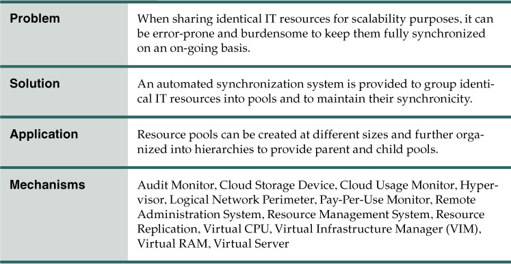
Problem
When assembling identical IT resources for sharing and scalability purposes (such as when applying Shared Resources (17) and Dynamic Scalability (25)), the IT resources need to carefully be kept synchronized so that no one IT resource differs from another.
Manually establishing and maintaining the level of required synchronicity across collections of shared IT resources is challenging, effort-intensive and, most importantly, error-prone. Variances or disparity between shared IT resources can lead to inconsistent runtime behavior and cause numerous types of runtime exceptions.
Solution
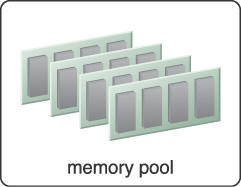
Identical IT resources are grouped into resource pools and maintained by a system that automatically ensures they remain synchronized (Figure 4.1). The following items are commonly pooled:
• physical servers
• virtual servers
• cloud storage devices
• internetwork and networking devices
• CPUs
• memory (RAM)

Figure 4.1 A sample resource pool comprised of four sub-pools of CPUs, memory, cloud storage devices, and virtual network devices.
Dedicated pools can be created for each of these items, or respective pools can be further grouped into a larger pool (in which case each individual pool becomes a sub-pool).
Application
As stated previously, this pattern is primarily applied in support of Shared Resources (17) and Dynamic Scalability (25) in order to establish a reliable system of shared IT resource synchronization. The Resource Pooling pattern itself can be further supported by the application of Resource Reservation (106).
Provided here are common examples of resource pools:

Physical server pools composed of ready-to-go, networked servers installed with operating systems and any other necessary programs or applications.

Virtual server pools are usually configured using templates that cloud consumers can choose from, such as a pool of mid-tier Windows servers with 4 GBs of RAM or a pool of low-tier Ubuntu servers with 2 GBs of RAM.
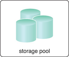
Storage pools (or cloud storage device pools) that consist of file-based or block-based storage structures. Storage pools can contain empty or filled cloud storage devices. Often storage resource pools will take advantage of LUNs.

Network pools (or interconnect pools) are composed of different, preconfigured network connectivity devices. For example, a pool of virtual firewall devices or physical network switches can be created for redundant connectivity, load balancing, or link aggregation.

CPU pools are ready to be allocated to virtual servers. These are often broken down into individual processing cores (as opposed to pooling entire CPUs).
Pools of physical RAM that can be used in newly provisioned physical servers or to vertically scale physical servers.
Resource pools can grow to become complex, with multiple pools created for specific cloud consumers or applications. To help with the organization of diverse resource pools, a hierarchical structure can be established to create parent, sibling, and nested pools.
Sibling resource pools are normally drawn from the same collection of physical IT resources (as opposed to IT resources spread out over different data centers) and are isolated from one another so that each cloud consumer is only provided access to its respective pool (Figure 4.2).

Figure 4.2 Pools B and C are sibling pools taken from the larger Pool A that has been allocated to a cloud consumer. This is an alternative to taking the IT resources for Pool B and Pool C from a general reserve of IT resources that is shared throughout the cloud.
In the nested pool model, larger pools are divided into smaller pools of the same kind (Figure 4.3). Nested pools can be used to assign resource pools to different departments or groups within the same cloud consumer organization.

Figure 4.3 Nested Pools A.1 and A.2 are comprised of the same IT resources as Pool A, but in different quantities. Nested pools are generally used to provision cloud services that are rapidly instantiated using the same kind of IT resources with the same configuration settings.
After resources pools have been defined, multiple instances of IT resources from each pool can be created to provide an in-memory pool of “live” IT resources.
Mechanisms
• Audit Monitor – This mechanism monitors resource pool usage to ensure compliance with privacy and regulation requirements, especially when pools include cloud storage devices or data loaded into memory.
• Cloud Storage Device – Cloud storage devices are commonly pooled as a result of the application of this pattern.
• Cloud Usage Monitor – Various cloud usage monitors can be involved with the runtime tracking and synchronization required by IT resources within pools and by the systems managing the resource pools themselves.
• Hypervisor – The hypervisor mechanism is responsible for providing virtual servers with access to resource pools, and hosting virtual servers and sometimes the resource pools themselves. Hypervisors further can distribute physical computing capacity between the virtual servers based on each virtual server’s configuration and priority.
• Logical Network Perimeter – The logical network perimeter can be used to logically organize and isolate the resource pools.
• Pay-Per-Use Monitor – The pay-per-use monitor collects usage and billing information in relation to how individual cloud consumers use and are allocated IT resources from various pools.
• Remote Administration System – This mechanism is commonly used to interface with backend systems and programs in order to provide resource pool administration features via a front-end portal.
• Resource Management System – The resource management system mechanism supplies cloud consumers with the tools and permission management options to administer resource pools.
• Resource Replication – This mechanism can be used to generate new instances of IT resources for a given resource pool.
• Virtual CPU – This mechanism is used to allocate CPU to virtual servers, and also helps to determine whether a hypervisor’s physical CPU is being over-utilized or a virtual server requires more CPU capacity. When a system has more than one CPU or when hypervisors belong to the same cluster, their total CPU capacity can be aggregated into a pool and leveraged by virtual servers.
• Virtual Infrastructure Manager (VIM) – This mechanism enables pools of resources to be created on individual hypervisors, and can also aggregate the capacity of multiple hypervisors into a pool from where virtual CPU and memory resources can be assigned to virtual servers.
• Virtual RAM – This mechanism is used to allocate memory to virtual servers, and to measure the memory utilization of hypervisors and virtual servers. When more than one hypervisor is present, a pool encompassing the combined memory capacity of the hypervisors can be created. This mechanism is also used to identify whether more memory should be added to a virtual server.
• Virtual Server – This mechanism is associated with the Resource Pooling pattern in how virtual server hosted IT resources are provisioned and consumed by resource pools that are assigned to cloud consumers. Virtual servers themselves may also be pooled.
Resource Reservation

How can shared IT resources be protected from conflicts that can arise from concurrent access?

Problem
When applying Shared Resources (17) and Resource Pooling (99) we can give multiple cloud service consumers access to the same IT resources. Depending on how IT resources are designed for shared usage and depending on their available levels of capacity, concurrent access can lead to a runtime exception condition called resource constraint.
A resource constraint is a condition that occurs when two or more cloud consumers have been allocated to share an IT resource that does not have the capacity to accommodate the entire processing requirements of the cloud consumers. As a result, one or more of the consumers will encounter degraded performance or be rejected altogether. The cloud service itself may go down, resulting in all cloud consumers being rejected.
Other types of runtime conflicts can occur when an IT resource (especially one not specifically designed to accommodate sharing) is concurrently accessed by different cloud service consumers. For example, nested and sibling resource pools introduce the notion of resource borrowing, whereby one pool can temporarily borrow IT resources from other pools. A runtime conflict can be triggered when the borrowed IT resource is not returned due to prolonged usage by the cloud service consumer that is borrowing it. This can inevitably lead back to the occurrence of resource constraints.
Solution
An IT resource reservation system is established to protect cloud service consumers (“tenants”) sharing the same underlying IT resources from each other. This system essentially guarantees a minimum amount of an IT resource for each cloud consumer by putting it aside and making it exclusively available only to the designated cloud service consumer. Potential conflicts, such as resource constraints and resource borrowing, are avoided because the reserved IT resources are never actually shared.
Application
Creating an IT resource reservation system requires the involvement of the resource management system mechanism that can be used to define IT resource usage thresholds for individual IT resources and resource pools. Reservations are created to lock the amount of IT resources that each pool must keep. The balance of IT resources within a pool can still be shared (and borrowed).
The following steps are shown in Figures 4.4 to 4.6:
1. A physical resource group is created.
2. A parent resource pool is created from the physical resource group by applying Resource Pooling (99).
3. Two smaller child pools are created from the parent resource pool, and resource limits are defined using the resource management system mechanism.
4. Cloud consumers are provided with access to their own exclusive resource pools.
5. There is an increase in requests from Cloud Consumer A, resulting in more IT resources being allocated.
6. Consequently, some IT resources are borrowed from Pool 2. The amount of borrowed resources, however, is pre-determined by the resource limit defined in Step 3, which ensures that Cloud Consumer B will not face resource constraints.
7. Cloud Consumer B now imposes more requests and usage demands and may soon need to utilize all available IT resources in the pool.
8. The resource management system forces Pool 1 to release the IT resources and move them back to Pool 2 to become available for Cloud Consumer B.

Figure 4.4 A resource pool hierarchy to which an IT resource reservation system is applied (Part I).
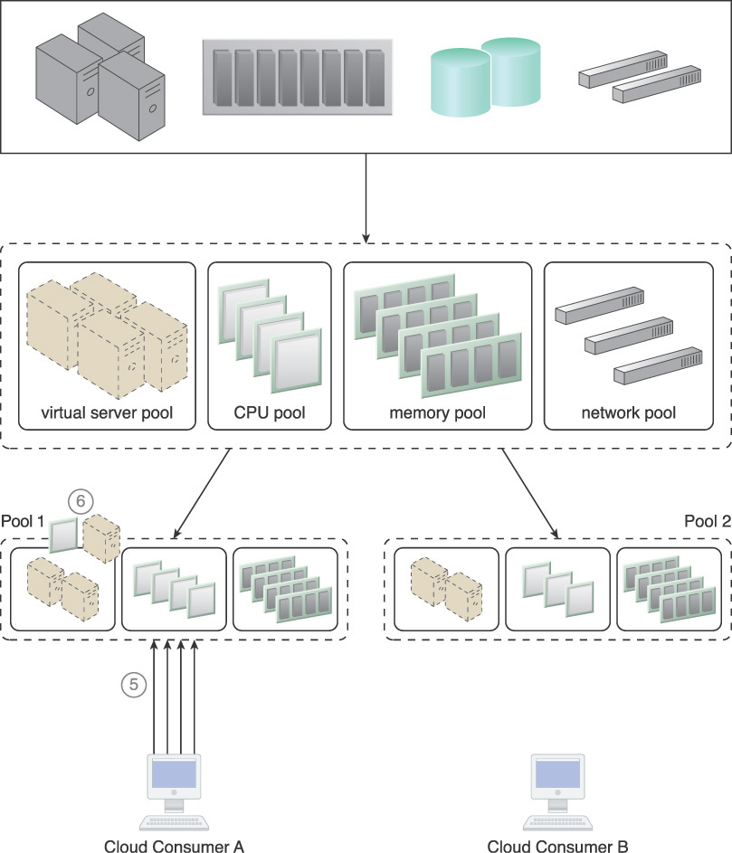
Figure 4.5 A resource pool hierarchy to which an IT resource reservation system is applied (Part II).
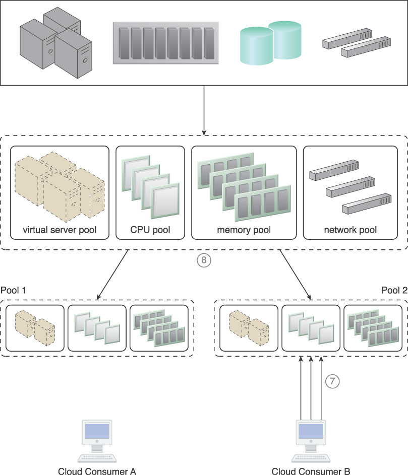
Figure 4.6 A resource pool hierarchy to which an IT resource reservation system is applied (Part III).
Mechanisms
• Audit Monitor – The audit monitor may be responsible for ensuring that the resource reservation system is acting in compliance with cloud consumer auditing, privacy, and other regulatory requirements. The audited information may also pertain to the geographical location of the reserved IT resources.
• Cloud Storage Device – This mechanism may be an IT resource reserved by this system.
• Cloud Usage Monitor – A cloud usage monitor may be involved with monitoring thresholds that trigger the allocation of reserved IT resources.
• Hypervisor – The hypervisor mechanism is associated with this pattern in its commitment to applying reservations for different cloud consumers in order to ensure that they are allocated the guaranteed amounts of IT resources. In support of this, it is responsible for locking, and pre-allocating the virtual servers’ reserved computing capacity based on their configurations.
• Logical Network Perimeter – This mechanism ensures that reserved IT resources are made exclusively available to the appropriate cloud consumers.
• Remote Administration System – This system provides the tools necessary for custom front-ends to provide the administration controls necessary for cloud consumers to create and manage reserved IT resource allocations.
• Resource Management System – The resource management system provides essential features for managing IT resource reservations. These features may be encapsulated by a portal produced via the remote administration system mechanism.
• Resource Replication – The resource replication mechanism needs to stay updated on any cloud consumer IT resource consumption limitations to determine when new IT resource instances need to be replicated and provisioned.
• Virtual CPU – This mechanism is used to define the computing capacity a virtual server needs to have reserved. When this mechanism is used, a specific amount of CPU is explicitly allocated to each virtual server and not shared with other virtual servers.
• Virtual Infrastructure Manager (VIM) – This mechanism is used to configure the resources that are reserved for each virtual server.
• Virtual RAM – This mechanism is used to configure the memory that virtual servers need reserved and guaranteed. The memory that is reserved for each virtual server is not allocated to or shared with other virtual servers.
• Virtual Server – This mechanism hosts the reserved IT resources that are allocated.
Hypervisor Clustering

How can a virtual server survive the failure of its hosting hypervisor or physical server?

Problem
Virtual servers run on a hypervisor, and hardware resources are emulated for the virtual servers via the hypervisors. If the hypervisor fails or if the underlying physical server fails (thereby causing the hypervisor to fail), the failure condition cascades to all of its hosted virtual servers.
The following steps are shown in Figure 4.7:
1. Physical Server A hosts a hypervisor that hosts Virtual Servers A and B.
2. When Physical Server A fails, the hypervisor and the two virtual servers fail as well.

Solution
A high-availability hypervisor cluster is created to establish a group of hypervisors that span physical servers. As a result, if a given physical server or hypervisor becomes unavailable, hosted virtual servers can be moved to another physical server or hypervisor (Figure 4.8).
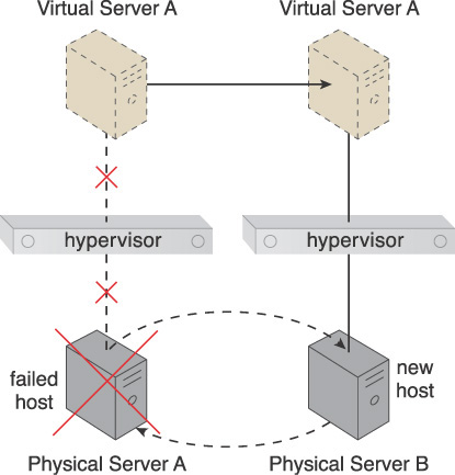
Figure 4.8 Physical Server A becomes unavailable, thereby bringing down its hypervisor. Because the hypervisor is part of a cluster, Virtual Server A is migrated to a different host (Physical Server B), which has another hypervisor that is part of the same cluster.
Application
A hypervisor cluster architecture is established and controlled via a central VIM, which sends regular heartbeat messages to the hypervisors to confirm that they are up and running. Any heartbeat messages that are not successfully acknowledged can lead the VIM to initiate the live VM migration program in order to dynamically move affected virtual servers to a new host. The hypervisor cluster utilizes a shared cloud storage device, which is used during the live migration of virtual servers by different hypervisors in the cluster.
Figures 4.9 to 4.12 provide examples of the results of applying the Hypervisor Clustering pattern, accompanied by numbered steps.

Figure 4.9 A cloud architecture resulting from the application of the Hypervisor Clustering pattern (Part I). These initial steps detail the assembly of required components.

Figure 4.10 A cloud architecture resulting from the application of the Hypervisor Clustering pattern (Part II).
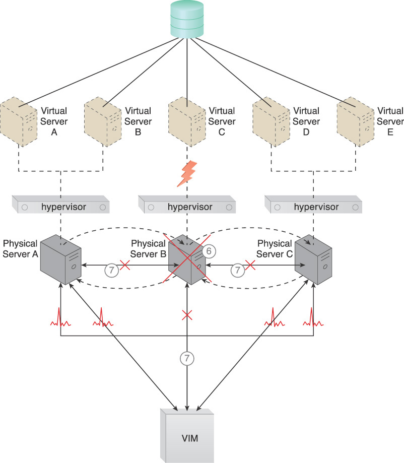
Figure 4.11 A cloud architecture resulting from the application of the Hypervisor Clustering pattern (Part III).

Figure 4.12 A cloud architecture resulting from the application of the Hypervisor Clustering pattern (Part IV).
1. Hypervisors are installed on the three physical servers.
2. Virtual servers are created by the hypervisors.
3. A shared cloud storage device containing virtual server configuration files is positioned so that all hypervisors have access to it.
4. The hypervisor cluster is enabled on the three physical server hosts via a central VIM.
5. The physical servers exchange heartbeat messages with each other and the VIM, based on a predefined schedule.
6. Physical Server B fails and becomes unavailable, jeopardizing Virtual Server C.
7. The VIM and the other physical servers stop receiving heartbeat messages from Physical Server B.
8. Based on the available capacity of other hypervisors in the cluster, the VIM chooses Physical Server C as the new host to take ownership of Virtual Server C.
9. Virtual Server C is live-migrated to the hypervisor running on Physical Server C, where it may need to be restarted before continuing to operate normally.
Mechanisms
• Cloud Storage Device – The cloud storage device mechanism acts as a central repository that hosts the virtual server folders, so that the folders and virtual server configurations are accessible to all of the hypervisors participating in the cluster.
• Hypervisor – The hypervisor is the primary mechanism by which this pattern is applied. It acts as a member of the cluster and hosts the virtual servers. If a hypervisor fails, one of the other available hypervisors restarts its virtual machine to recover the hosted virtual servers from failure.
• Logical Network Perimeter – This mechanism creates logical boundaries that ensure that none of the hypervisors of other cloud consumers are accidentally included in a given cluster.
• Resource Cluster – The resource cluster is the fundamental mechanism used to create and initiate hypervisor clusters.
• Resource Replication – Each hypervisor informs others in the cluster about its status and availability. When a part of cluster configuration needs to be changed, for instance when a virtual switch is created, deleted, or modified, then this update may need to be replicated to all hypervisors via the VIM.
• Virtual Infrastructure Manager (VIM) – This mechanism is used to create and configure the hypervisor cluster, add cluster members to the cluster, and cascade the cluster configuration to cluster members.
• Virtual Server – Virtual servers represent the type of mechanism that is protected by the application of this pattern.
• Virtual Switch – This mechanism is used to ensure that any virtual servers retrieved from hypervisor failure will be accessible to cloud consumers.
• Virtualization Monitor – This mechanism is responsible for actively monitoring the hypervisors, and sending alerts whenever one of the hypervisors in the cluster fails.
Redundant Storage

How can the reliability and availability of cloud storage devices survive failure conditions?
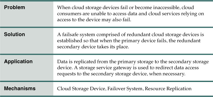
Problem
Cloud storage devices are subject to failure and disruption due to a variety of causes, including network connectivity issues, controller failures, general hardware failure, and security breaches. When the reliability of a cloud storage device is compromised, it can have a ripple effect, causing impact failure across any cloud services, cloud-based applications, and cloud infrastructure program and components that rely on its presence and availability.
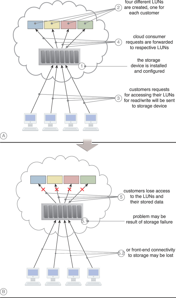
The following steps are shown in Figure 4.13:
1. The cloud storage device is installed and configured.
2. Four LUNs are created, one for each cloud consumer.
3. Each cloud consumer sends a request to access its own LUN.
4. The cloud storage device receives the requests and forwards them to the respective LUN.
5. The cloud storage device fails and cloud consumers lose access to their LUNs. This may be due to the loss of the device controller (5.1) or loss of connectivity (5.2).
Solution
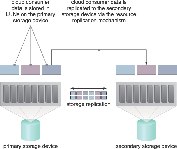
A secondary redundant cloud storage device is incorporated into a system that synchronizes its data with the data in the primary cloud storage device. When the primary device fails, a storage service gateway diverts requests to the secondary device.
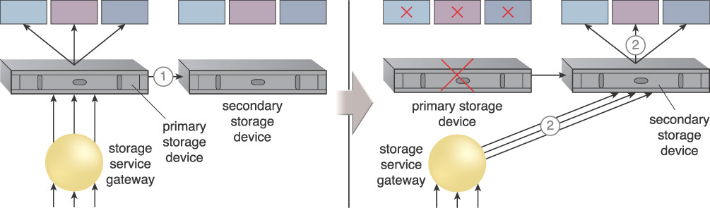
The following steps are shown in Figure 4.14:
1. The primary cloud storage device is replicated to the secondary cloud storage device on a regular basis.
2. The primary storage becomes unavailable and the storage service gateway forwards the cloud consumer requests to the secondary storage device.
3. The secondary storage forwards the requests to the LUNs, allowing cloud consumers to continue to access to their data.
Application
This pattern fundamentally relies on the resource replication mechanism to keep the primary cloud storage device synchronized with any additional duplicate secondary cloud storage devices that comprise the failover system (Figure 4.15).
Cloud providers may locate secondary cloud storage devices in a different geographical region than the primary cloud storage device, usually for economic reasons. For some types of data, this may introduce legal concerns. The location of the secondary cloud storage device can dictate the protocol and method used for synchronization because some replication transport protocols have distance restrictions.
Some cloud providers use storage devices with dual array and storage controllers to improve device redundancy. They may place the secondary storage device in a different physical location for cloud balancing and disaster recovery purposes. In this case, cloud providers may need to lease a network connection via a third-party cloud provider, to establish replication between two devices.
Mechanisms
• Cloud Storage Device – This is the mechanism to which the pattern is primarily applied.
• Failover System – The application of the Redundant Storage pattern results in a specialized failover system based on the use of duplicate storage devices and a storage service gateway.
• Resource Replication – The failover system created by the application of this pattern relies on this mechanism to keep cloud storage devices synchronized.
Dynamic Failure Detection and Recovery

How can the notification and recovery of IT resource failure be automated?

Problem
Cloud environments can be comprised of vast quantities of IT resources being accessed by numerous cloud consumers. Any of those IT resources can experience predictable failure conditions that require intervention to resolve. Manually administering and solving standard IT resource failures in cloud environments is generally inefficient and impractical.
Solution
A resilient watchdog system is established to monitor and respond to a wide range of pre-defined failure scenarios. This system is further able to notify and escalate certain failure conditions that it cannot automatically solve itself.
Application
The resilient watchdog system relies on a specialized cloud usage monitor (that can be referred to as the intelligent watchdog monitor) to actively monitor IT resources and take pre-defined actions in response to pre-defined events (Figures 4.16 and 4.17).

Figure 4.16 The intelligent watchdog monitor keeps track of cloud consumer requests (1) and detects that a cloud service has failed (2).

Figure 4.17 The intelligent watchdog monitor notifies the watchdog system (3), which restores the cloud service based on predefined policies (4).
The resilient watchdog system, together with the intelligent watchdog monitor, performs the following five core functions:
• watching
• deciding upon an event
• acting upon an event
• reporting
• escalating
Sequential recovery policies can be defined for each IT resource to determine how the intelligent watchdog monitor should behave when encountering a failure condition (Figure 4.18). For example, a recovery policy may state that before issuing a notification, one recovery attempt should be carried out automatically.

Figure 4.18 In the event of any failures, the active monitor refers to its predefined policies to recover the service step by step, escalating the processes as the problem proves to be deeper than expected.
When the intelligent watchdog monitor escalates an issue, there are common types of actions it may take, such as:
• running a batch file
• sending a console message
• sending a text message
• sending an email message
• sending an SNMP trap
• logging a ticket in a ticketing and event monitoring system
There are varieties of programs and products that can act as an intelligent watchdog monitor. Most can be integrated with standard ticketing and event management systems.
Mechanisms
• Audit Monitor – This mechanism may be required to ensure that the manner in which this pattern is carried out at runtime is in compliance with any related legal or policy requirements.
• Cloud Usage Monitor – Various specialized cloud usage monitors may be involved with monitoring and collecting IT resource usage data as part of failure conditions and recovery, notification, and escalation activity.
• Failover System – Failover is fundamental to the application of this pattern, as the failover system mechanism is generally utilized during the initial attempts to recover failed IT resources.
• SLA Management System and SLA Monitor – The functionality introduced by the application of the Dynamic Failure Detection and Recovery pattern is closely associated with SLA guarantees and therefore commonly relies on the information managed and processed by these mechanisms.
Multipath Resource Access

How can an IT resource be accessed when its pre-defined path is lost or becomes unavailable?

Problem
Certain IT resources can only be accessed using an assigned path (hyperlink) that leads to the location of the IT resources. The path can be inadvertently lost or incorrectly defined by the cloud consumer or changed by the cloud provider. When a cloud consumer no longer possesses the correct and exclusive path to an IT resource, this IT resource becomes inaccessible and unavailable (Figure 4.19). When this unavailability occurs without warning at runtime, exception conditions can result that compromise the stability of larger cloud solutions that depend on the IT resource’s availability.
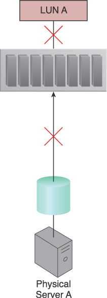
Figure 4.19 Physical Server A is connected to LUN A via a single fiber channel, and uses the LUN to store different types of data. The fiber channel connection becomes unavailable due to an HBA card failure and invalidates the path used by Physical Server A, which has now lost access to LUN A and all of its stored data.
Solution
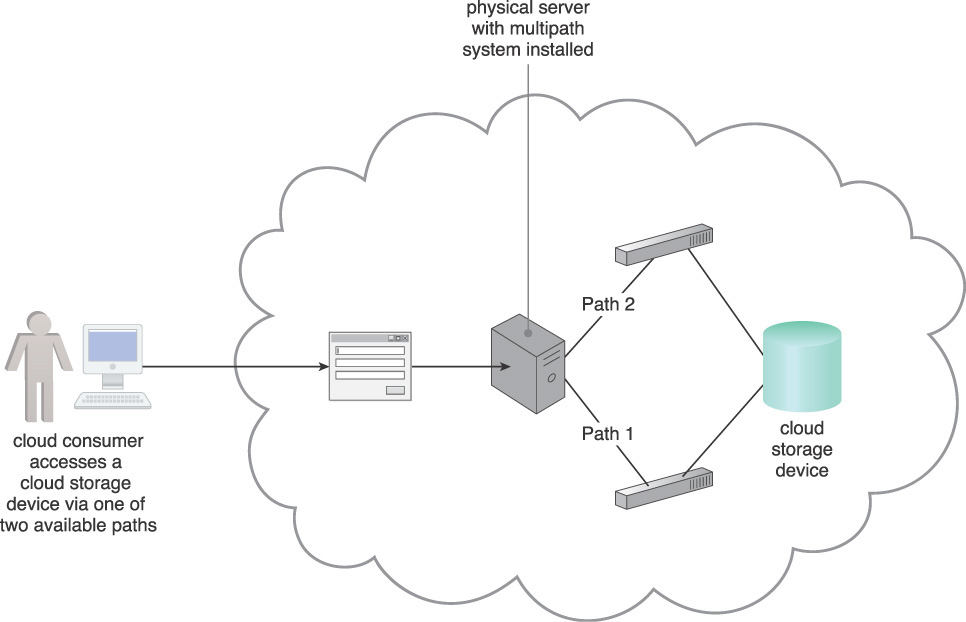
A multipathing system is established to provide alternative paths to IT resources providing cloud consumers with a means of programmatically or manually overcoming path failures (Figure 4.20).
Application
The application of this pattern requires the use of a multipathing system and the creation of alternative paths (or hyperlinks) that are assigned to specific IT resources. The alternative paths may be physical or virtual. The multipathing system resides on the server or hypervisor, and ensures that each IT resource can be seen via each alternative path identically.
The following steps are shown in Figure 4.21:
1. Physical Server A is connected to the LUN A storage device via two different paths.
2. LUN A is seen as different LUNs from each of the two paths.
3. The multipathing system is put in place and configured.
4. LUN A is seen as one identical LUN from both paths.
5. Physical Server A has access to LUN A from two different paths.
6. A link failure occurs and one of the paths becomes unavailable.
7. Physical Server A can still use LUN A because the other link remains active.

In some cases, a specific driver is required by the operating system to ensure that it understands the redundant paths and does view two paths leading to the same IT resource as two separate IT resources, as shown in Figure 4.22.

Figure 4.22 A multipath driver is installed on a server to ensure that the operating system understands the redundant paths and views two paths leading to the same IT resource as two separate IT resources.
Mechanisms
• Cloud Storage Device – The cloud storage device is a common IT resource that may require the creation of an alternative path in order to remain accessible by solutions that rely on data access.
• Hypervisor – An alternate path to a hypervisor is required to have a redundant link to the hosted virtual servers.
• Logical Network Perimeter – This mechanism guarantees that the privacy of cloud consumers is upheld even when multiple paths to the same IT resource are created.
• Resource Replication – The resource replication mechanism is required when it is necessary to create a new instance of an IT resource in order to generate the alternative path.
• Virtual Server – This mechanism is associated with Multipath Resource Access in how it hosts services that have multipath access via different links or virtual switches. In some cases, the hypervisor itself provides multipath access to the virtual server.
Redundant Physical Connection for Virtual Servers

How can a virtual server be kept connected when its physical connection fails?

Problem
A virtual server is connected to an external network via a virtual switch uplink port. If the uplink fails (due to, for example, cable disconnection or port failure), the virtual server becomes isolated and disconnects from the external network.
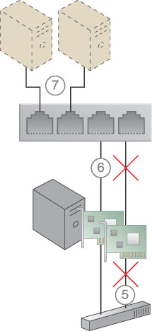
The following steps are shown in Figure 4.23:
1. A physical network adapter installed on the physical server host is connected to the physical switch on the network.
2. A virtual switch is created for use by two virtual servers. Because it requires access to the physical external network, the physical network adapter is attached to the virtual switch to be used as an uplink to the network.
3. The virtual servers communicate with the external network via the attached physical uplink network card.
4. A connection failure occurs, either because of a physical link connectivity issue between the physical adapter and the physical switch (4.1), or because of a physical network card failure (4.2).
5. The virtual servers lose access to the physical external network and are no longer accessible by their cloud consumers.

Figure 4.23 The steps that can lead to the separation of virtual servers from their external network connection.
Solution
One or more redundant uplink connections are established and positioned in standby mode. A redundant uplink connection is available to take over as the active uplink connection whenever the primary uplink connection becomes unavailable or experiences failure conditions (Figure 4.24).

Figure 4.24 Redundant uplinks are installed on a physical server hosting several virtual servers. When one fails, another takes over to maintain the virtual servers’ active network connections.
Application
While the main uplink is working, virtual servers connect to the outside via that port. As soon as it fails, the standby uplink will automatically become the active uplink, and the server will send the packets to the outside via the new uplink. This process is also transparent to virtual servers and users.
While the second NIC is connected and receives the virtual server’s packets, it is not forwarding any traffic while the primary uplink is alive. If, and when, the primary uplink fails, the secondary uplink starts to forward the packets without any pause or interruption. If the failed uplink happens to come back into operation, it will take over the lead role and the second NIC goes into standby mode again.
The following steps are shown in Figures 4.25 and 4.26:
1. A new network adapter is added to support a redundant uplink.
2. Both network cards are connected to the physical external switch.
3. Both physical network adapters are configured to be used as uplink adapters for the virtual switch.
4. One physical network adapter is designated as the primary adapter, whereas the other is designated as the secondary adapter providing the standby uplink. The secondary adapter does not forward any packets.
5. The primary uplink forwards packets to the external network until it becomes unavailable.
6. When required, the secondary standby uplink automatically becomes the primary uplink and uses the virtual switch to forward the virtual servers’ packets to the external network.
7. The virtual servers stay connected to the external physical network, without interruptions.

Mechanisms
• Failover System – The failover system is utilized to perform the failover of an unavailable uplink to a standby uplink.
• Hypervisor – The hypervisor hosts the virtual servers and some of the virtual switches, and provides virtual networks and virtual switches with access to the virtual servers. If a virtual switch’s physical uplink becomes unavailable, this mechanism is responsible for forwarding the virtual servers’ traffic using another available physical uplink on the virtual switch.
• Logical Network Perimeter – Logical network perimeters ensure that the virtual switches that are allocated or defined for each cloud consumer remain isolated.
• Physical Uplink – This mechanism is used to establish connectivity between virtual switches and physical switches. Additional physical uplinks can be attached to a virtual switch to improve redundancy.
• Resource Replication – Resource replication is used to replicate the current status of the active uplink to a standby uplink, so that the connection remains active without disruption.
• Virtual Infrastructure Manager (VIM) – This mechanism is used to configure virtual switches and their uplinks, and performs the configurations on the hypervisors so that they can use another available uplink should an active uplink fail.
• Virtual Server – This pattern is primarily applied in support of maintaining the network connections for virtual servers.
• Virtual Switch – This mechanism uses the attached physical uplinks to establish physical connection redundancy that allows virtual servers to be redundantly connected to cloud consumers and the physical network.
Synchronized Operating State

How can the availability and reliability of virtual servers be ensured when high availability and clustering technology is unavailable?
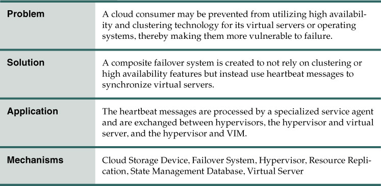
Problem
Technical restrictions, licensing restrictions, or other reasons may prevent a cloud consumer from taking advantage of clustering and high availability technology and products. This can seriously jeopardize the availability and scalability of its cloud services and applications.
Solution
A system comprised of a set of mechanisms and relying on the use of heartbeat messages is established to emulate select features of clustering and high availability IT resources (Figure 4.27).

Figure 4.27 Special heartbeat agents are employed to monitor heartbeat messages exchanged between the servers.
Application
Heartbeat messages are processed by a heartbeat monitor agent and are exchanged between:
• hypervisors
• each hypervisor and each virtual server
• each hypervisor and the central VIM
If an operating system is placed on a physical server, it needs to be converted into a virtual server prior to the issuance of heartbeat messages.
The following steps are shown in Figure 4.28:
1. A virtual server is created from the physical server.
2. The hypervisor proceeds to host the virtual server.
3. The primary virtual server is equipped with fault tolerance and maintains a synchronized state via the use of heartbeat messages.
4. The secondary server that shares the synchronized state is available in case the primary virtual server fails.

The application/service monitoring station monitors the servers and cloud services. In the event of failure, this station attempts recovery based on sequential pre-defined policies. If the primary server’s operating system fails, procedures are in place to avoid downtime (Figure 4.29).
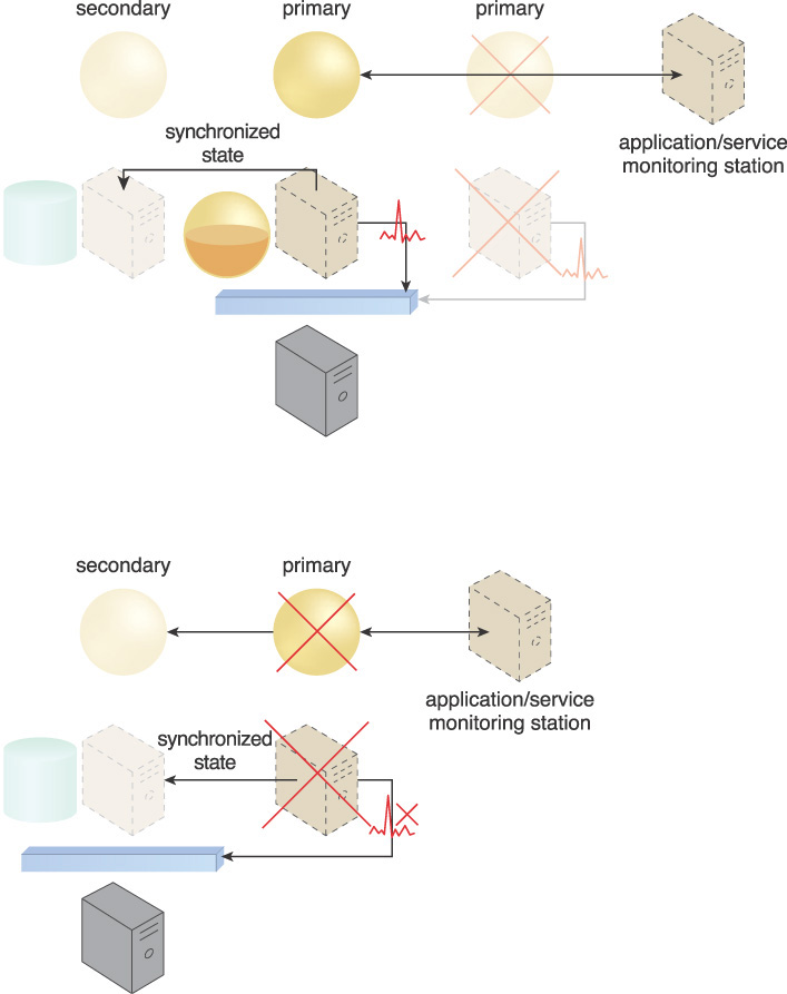
Figure 4.29 When the primary virtual server fails, along with its hosted cloud service, heartbeat messages are no longer transmitted. As a result, the hypervisor recognizes the failure and switches activity to the secondary virtual server that maintains the synchronized state. After the primary virtual server is back online, the hypervisor creates a new secondary for the new primary, and proceeds to save it as a synchronized non-active state.
Mechanisms
• Cloud Storage Device – Cloud storage devices may be used to host the primary and secondary (shadow) copies of virtual server data and cloud service instances.
• Failover System – The failover system is responsible for providing failsafe logic in support of switch cloud consumer requests from a primary virtual server to a secondary virtual server.
• Hypervisor – The hypervisor hosts the primary and secondary (shadow) state data, in addition to providing the features that resource replication needs to replicate the primary state.
• Resource Replication – Resource replication performs the replication of the primary virtual server state to a secondary (shadow) copy.
• State Management Database – The state management database actively stores and restores secondary operating state data in support of primary virtual server failure and recovery.
• Virtual Server – Virtual servers are the primary mechanism to which this pattern is applied.
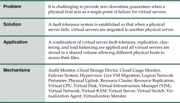
Problem
A physical server naturally acts as a single point of failure for the virtual servers it hosts. As a result, when the physical server fails or is compromised, the availability of any (or all) hosted virtual servers can be affected. This makes the issuance of zero downtime guarantees by a cloud provider to cloud consumers challenging.
Solution
A failover system is established so that virtual servers are dynamically moved to different physical server hosts in the event that their original physical server host fails. For example, in Figure 4.30, Virtual Server A is dynamically moved to another physical server host.
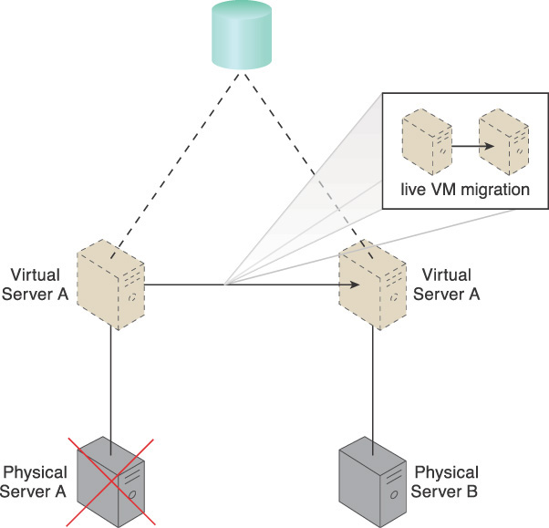
Figure 4.30 Physical Server A fails, triggering the live VM migration program to dynamically move Virtual Server A to Physical Server B.
Application
Multiple physical servers are assembled into a group that is controlled by a fault tolerance system capable of switching activity from one physical server to another, without interruption. Resource cluster and live VM migration components are commonly part of this form of high availability cloud architecture.
The resulting fault tolerance assures that, in case of physical server failure, hosted virtual servers will be migrated to a secondary physical server. All virtual servers are stored on a shared volume (as per Persistent Virtual Network Configuration (227)) so that other physical server hosts in the same group can access their files.
Live storage replication can further be utilized to guarantee that virtual server files and hard disks remain available via secondary storage devices.
Mechanisms
• Audit Monitor – This mechanism may be required to ensure that the relocation of virtual servers does not relocate hosted data to prohibited locations.
• Cloud Storage Device – A cloud storage device is used to store virtual server network configuration data shared by the physical servers. It stores virtual servers and virtual disks in a central repository so that other available hypervisors can access the files and power on the failed virtual servers in case one of the hypervisors fails.
• Cloud Usage Monitor – Incarnations of this mechanism are used to monitor the actual IT resource usage of cloud consumers to help ensure that virtual server capacities are not exceeded.
• Failover System – The failover system can be used to switch from a failed primary physical server to a secondary physical server.
• Hypervisor – The hypervisor of each affected physical server hosts the affected virtual servers.
• Live VM Migration – When multiple instances of the same service or virtual server are provisioned for the purpose of redundancy and availability, this mechanism is used to seamlessly distribute different instances of the same service between different hypervisors to make sure one hypervisor will not become a single point of failure.
• Logical Network Perimeter – Logical network perimeters provide and maintain the isolation that is required to ensure that each cloud consumer remains within its own logical boundary subsequent to virtual server relocation.
• Physical Uplink – Physical uplinks are used and deployed in a redundant model, so that the virtual servers and services will not lose their connectivity to the cloud service consumers if a physical uplink fails or becomes disconnected.
• Resource Cluster – The resource cluster mechanism is applied to create different types of active/active cluster groups that collaboratively improve the availability of virtual server-hosted IT resources.
• Resource Replication – This mechanism can create new virtual server and cloud service instances upon primary virtual server failure.
• Virtual CPU – The virtual CPU mechanism is used to provide CPU cycling, scheduling, and processing capabilities to the virtual servers.
• Virtual Disk – This mechanism is used to allocate local storage space to the hosted virtual servers.
• Virtual Infrastructure Manager (VIM) – This mechanism is used to control the availability and redundancy of the virtual servers and services, and initiates proper command when rebalancing the environment or recreating a new instance of a service or virtual server is required.
• Virtual Network – This mechanism is used to connect virtual servers and the services hosted on top of them.
• Virtual RAM – This mechanism is used to establish access for the virtual servers and applications to the physical memory installed on the physical server.
• Virtual Server – This is the mechanism to which this pattern primarily applied.
• Virtual Switch – This mechanism is used to connect hosted virtual servers to the physical network and external cloud service consumers using physical uplinks.
• Virtualization Agent – Virtual servers use this mechanism to send regular heartbeat messages to the hypervisor. A recovery process is initiated if the hypervisor does not receive heartbeats after an extended period of time.
• Virtualization Monitor – This mechanism is used to monitor the virtual servers’ availability and operational status.
Storage Maintenance Window
How can access to data in a cloud storage device be preserved during a maintenance outage?

Problem
Cloud storage devices subject to maintenance and administrative tasks may need to be temporarily shut down, thereby causing an outage to cloud service consumers and IT resources that require access to the devices and the data they host (Figure 4.31).
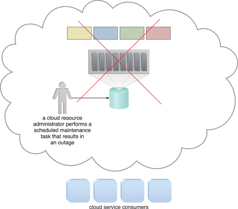
Figure 4.31 The maintenance task carried out by a cloud resource administrator causes an outage for the cloud storage device. Resultantly, the cloud storage device becomes unavailable to cloud service consumers.
Solution
Prior to a cloud storage device undergoing a maintenance outage, its data can be temporarily moved to a duplicate, secondary cloud storage device. Cloud service consumers are automatically and transparently redirected to the secondary cloud storage device and are unaware that the primary cloud storage device has been taken offline.
Application
Live storage migration is used to convert the data as a whole into an isolated mode and move it to the secondary cloud storage device, as shown in Figures 4.32 to 4.37.


Figure 4.33 Live storage migration moves the LUNs from the primary storage device to a secondary storage device.
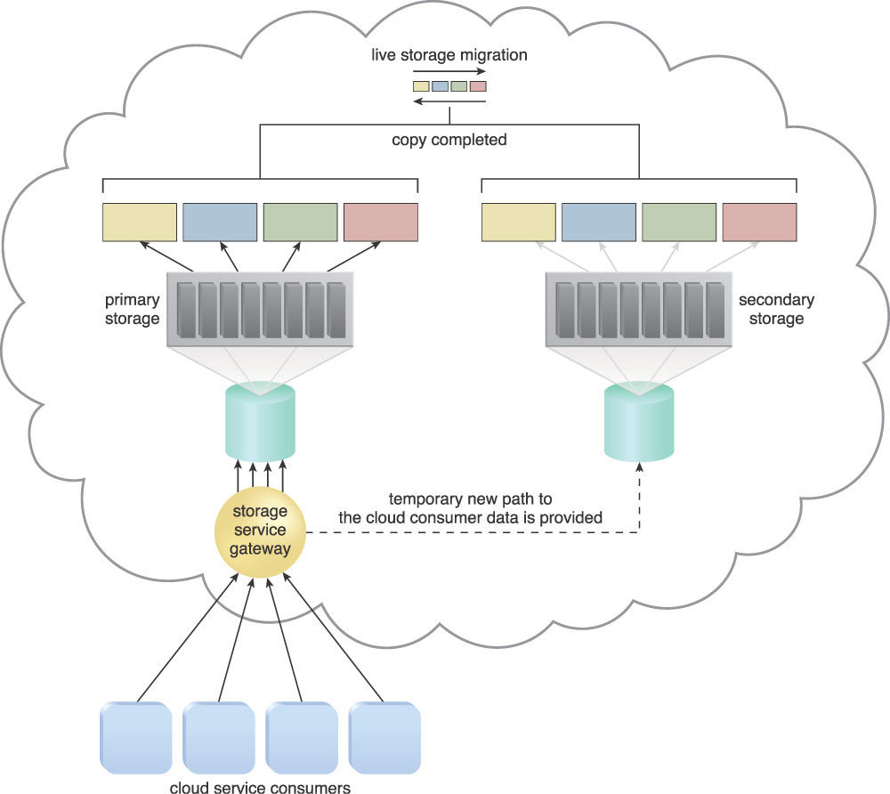
Figure 4.34 When the LUN’s data has been migrated, requests for the data are forwarded to the duplicate LUNs on the secondary storage device.

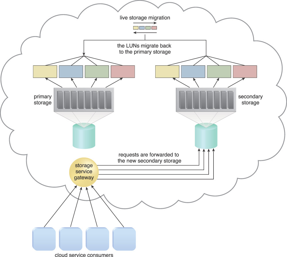
Figure 4.36 When it is confirmed that the maintenance task on the primary storage device has been completed, the primary storage is brought back online. Live storage migration subsequently restores the LUN data from the secondary storage device to the primary storage device.

Figure 4.37 When the LUN migration is completed, all data access requests are forwarded back to the primary storage device.
Mechanisms
• Cloud Storage Device – This is the primary mechanism to which this pattern is applied.
• Failover System – Although the migration is often pre-scheduled when this pattern is applied, both manually and automatically initiated failover can be incorporated into this cloud architecture.
• Resource Replication – The resource replication mechanism is used to keep the primary and secondary storage devices synchronized.
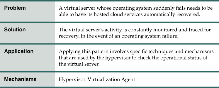
Virtual Server Auto Crash Recovery

In the event that a virtual server’s operating system crashes, how can the hosted cloud services be automatically recovered?
Problem
When the operating system of a virtual server fails or crashes, the cloud services that are hosted on this virtual server also become unavailable. This can in turn cause an outage or even an SLA breach, since some organizations have little to no tolerance for outages.
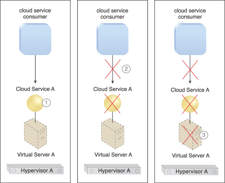
The following steps are shown in Figure 4.38:
1. Cloud Service A is running on Virtual Server A.
2. Cloud consumers suddenly cannot access the service.
3. An investigation shows that Hypervisor A is working fine and has been allocating resources to Virtual Server A. However, Virtual Server A’s resource usage is zero. Further investigation reveals that its operating system has crashed, which is why Cloud Service A is not working.
The system administrator has to manually reboot Virtual Server A in order to bring it back into operation.
Solution
Applying this pattern ensures that the operational status of a given virtual server is always being checked by the hypervisor on a routine basis. If the virtual server is not running or shows no signs of operation after a certain length of time, then the hypervisor takes action and restarts the virtual server automatically, to recover the virtual server from a crash.
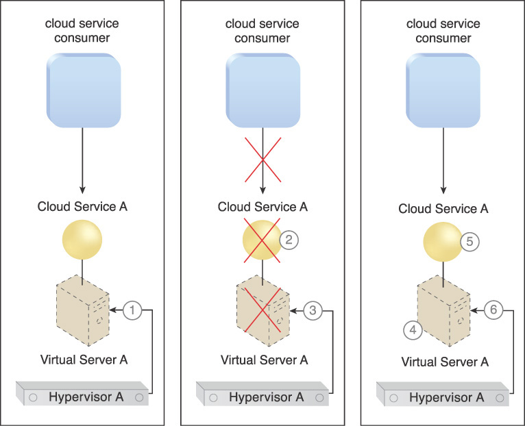
The scenario that results is illustrated in Figure 4.39 in the following steps:
1. Hypervisor A is monitoring Virtual Server A’s operational status.
2. Cloud Service A becomes unavailable due to an operating system failure on Virtual Server A.
3. Hypervisor A becomes aware of the nonoperational status of Virtual Server A immediately.
4. Hypervisor A restarts Virtual Server A.
5. Service resumes without requiring human interaction and cloud consumers can access the virtual server.
6. Hypervisor A continues to monitor the operational status of Virtual Server A.
Application
This pattern can be applied in different ways, depending on the brand and model of the hypervisor and the mechanism used to track the resource utilization of the virtual servers. The following chart in Figure 4.40 illustrates the steps involved in applying the pattern.
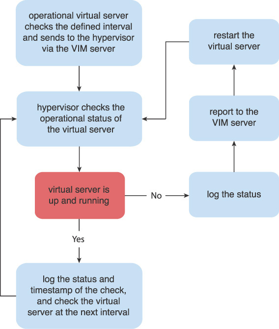
Different methods and mechanisms can be used to check the virtual server’s operational status, such as a mechanism that can install an agent inside the virtual server that reports back to the hypervisor. Another mechanism is a hypervisor that checks the resource usage of the virtual server, including memory and CPU usage, at pre-defined intervals. A different method is to check the virtual server’s network traffic and storage traffic for communication over the network and whether it is accessing or requesting any storage.
While this pattern ensures that virtual servers, applications, and services are operational and can be automatically recovered in the case of an operating system failure, this pattern may also restart the virtual server as a result of a “false positive.”
Mechanisms
• Hypervisor – The hypervisor mechanism hosts the virtual servers and is responsible for making sure the virtual servers are up and running. Any failed or crashed virtual servers are restarted by this mechanism.
• Virtualization Agent – This mechanism establishes one-way communication via specialized messages that are sent by the virtual servers to the host hypervisor at frequent and regular intervals to confirm virtual server operation.
Non-Disruptive Service Relocation
How can cloud service activity be temporarily or permanently relocated without causing service interruption?

Problem
A cloud service can become unavailable due to a number of reasons, such as:
• The cloud service encounters more runtime usage demand than it has processing capacity to handle.
• The cloud service implementation needs to undergo a maintenance update that mandates a temporary outage.
• The cloud service implementation needs to be permanently migrated to a new physical server host.
Cloud service consumer requests are rejected if a cloud service becomes unavailable, which can potentially result in exception conditions. Rendering the cloud service temporarily unavailable to cloud consumers is not preferred even if the outage is planned.
Solution
A system is established by which a pre-defined event triggers the duplication or migration of a cloud service implementation at runtime, thereby avoiding any disruption in service for cloud consumers.
An alternative to scaling cloud services in or out with redundant implementations, cloud service activity can be temporarily diverted to another hosting environment at runtime by adding a duplicate implementation onto a new host. Cloud service consumer requests can similarly be temporarily redirected to a duplicate implementation when the original implementation needs to undergo a maintenance outage. The relocation of the cloud service implementation and any cloud service activity can also be permanent to accommodate cloud service migrations to new physical server hosts.
Application
A key aspect to the underlying architecture is that the system ensures that the new cloud service implementation is successfully receiving and responding to cloud service consumer requests before the original cloud service implementation is deactivated or removed.
A common approach is to employ the live VM migration component to move the entire virtual server instance hosting the cloud service. The automated scaling listener and/or the load balancer mechanisms can be used to trigger a temporary redirection of cloud service consumer requests in response to scaling and workload distribution requirements. In this case either mechanism can contact the VIM to initiate the live VM migration process.
The steps involved in applying the Non-Disruptive Service Relocation pattern are illustrated in Figures 4.41 through 4.43.

Figure 4.41 An example of a scaling-based application of the Non-Disruptive Service Relocation pattern (Part I).

Figure 4.42 An example of a scaling-based application of the Non-Disruptive Service Relocation pattern (Part II).

Figure 4.43 An example of a scaling-based application of the Non-Disruptive Service Relocation pattern (Part III).
1. The automated scaling listener monitors the workload for a cloud service.
2. As the workload increases, a pre-defined threshold within the cloud service is reached.
3. The automated scaling listener signals the VIM to initiate the relocation.
4. The VIM signals both the origin and destination hypervisors to carry out a runtime relocation via the use of a live VM migration program.
5. A second copy of the virtual server and its hosted cloud service are created via the destination hypervisor on Physical Server B.
6. The state of both virtual server instances is synchronized.
7. The first virtual server instance is removed from Physical Server A after it is confirmed that cloud service consumer requests are being successfully exchanged with the cloud service on Physical Server B.
8. Cloud service consumer requests are only sent to the cloud service on Physical Server B from hereon.
Depending on the location of the virtual server’s disks and configuration, this migration can happen in one of two ways:
• If the virtual server disks are stored on a local storage device or on non-shared remote storage devices attached to the source host, then a copy of the virtual server disks is created on the destination host (either on a local or remote shared/non-shared storage device). After the copy has been created, both virtual server instances are synchronized and virtual server files are subsequently removed from the origin host.
• If the virtual server’s files are stored on a remote storage device shared between origin and destination hosts, there is no need to create the copy of virtual server disks. In this case, the ownership of the virtual server is simply transferred from the origin to the destination physical server host, and the virtual server’s state is automatically synchronized.
Note that this pattern conflicts and cannot be applied together with Direct I/O Access (169). A virtual server with direct I/O access is locked into its physical server host and cannot be moved to other hosts in this fashion.
Furthermore, Persistent Virtual Network Configuration (227) may need to be applied in support of this pattern so that by moving the virtual server, its defined network configuration is not inadvertently lost, which would prevent cloud service consumers from being able to connect to the virtual server.
Mechanisms
• Cloud Storage Device – This mechanism is fundamental to the Non-Disruptive Service Relocation pattern in how it provides the storage required to host data pertaining to the virtual servers in a central location.
• Cloud Usage Monitor – Cloud usage monitors are used to continuously track IT resource usage and activity of the system established by the Non-Disruptive Service Relocation pattern.
• Hypervisor – The hypervisor is associated with this pattern in how it is used to host the virtual servers that are hosting the cloud services that need to be relocated. It is further used to transfer a virtual server’s ownership and runtime, including CPU and memory state, from one hypervisor to another.
• Live VM Migration – This mechanism is responsible for transferring the ownership and runtime information of a virtual server from one hypervisor to another.
• Pay-Per-Use Monitor – The pay-per-use monitor is used to continuously collect the service usage costs of the IT resources at both their source and destination locations.
• Resource Replication – The resource replication mechanism is used to instantiate the shadow copy of the cloud service at its destination.
• SLA Management System – The SLA management system is responsible for acquiring SLA information from the SLA monitor, in order to obtain cloud service availability assurances both during and after the cloud service has been copied or relocated.
• SLA Monitor – This monitoring mechanism collects the aforementioned information required by the SLA management system.
• Virtual Infrastructure Manager (VIM) – This mechanism is used to initiate relocation, which can be automated in response to a threshold being reached or monitoring event.
• Virtual Server – Virtual servers generally host the cloud services at the source and destination locations.
• Virtual Switch – The virtual switch mechanism keeps virtual servers connected to and accessible over the network.