Chapter 5. Data Management and Storage Device Patterns

Single Root I/O Virtualization
Cloud Storage Data at Rest Encryption
Cloud Storage Data Lifecycle Management
Cloud Storage Data Placement Compliance Check
Cloud Storage Device Path Masking
Cloud Storage Device Performance Enforcement
The fundamental cloud computing model for enabling ubiquitous, on-demand, scalable network access to shared pools of configurable IT resources typically demands for the existence of and access to vast amounts of inexpensive storage that itself must be highly flexible, scalable, and configurable. As with other members of typical cloud architectures, cloud storage devices must have the ability to be rapidly provisioned and release storage resources and large amounts of data with minimal management effort or cloud provider interaction.
This set of patterns addresses key issues that pertain to common challenges and optimization requirements when configuring and managing cloud-based storage devices and the datasets they store.
Direct I/O Access
How can a virtual server overcome data transfer capacity thresholds imposed by its surrounding virtualization environment?
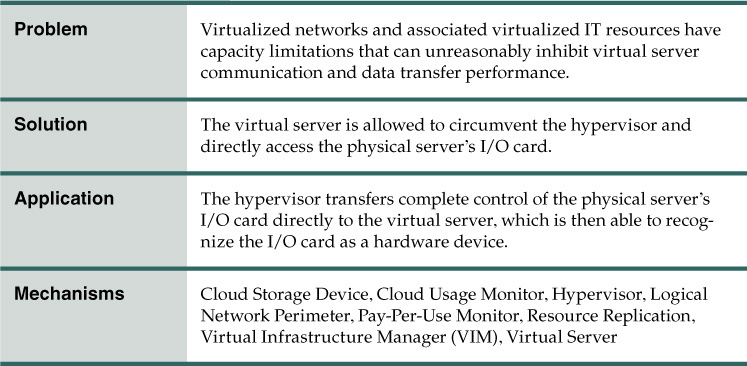
Problem
Access to the physical I/O cards that are installed on a physical server is usually provided to host virtual servers via I/O virtualization. However, virtual servers sometimes need to connect to and use an I/O card without any hypervisor interaction or emulation.
For example, there may be two application servers and one database connected to one another and installed as a virtual server. Direct access to the physical network must be made available in order to improve their connectivity (rather than sending traffic via the virtual network).
Solution
The cloud architecture permits connections to the physical I/O card directly by the virtual server, as an alternative to emulating such a connection via the hypervisor.
Application
To achieve this solution, the host CPU needs to support this type of access with the appropriate drivers installed on the virtual server for it to access the physical I/O card without hypervisor interaction, as shown in Figures 5.1 and 5.2. The virtual server will then be able recognize the I/O card as a hardware device.

Figure 5.1 Part A (left) shows the virtual server accessing a database stored on a SAN storage LUN. Connectivity from the virtual server to the database occurs via a virtual switch. Part B (right) depicts an increase in the amount of requests. The resulting bandwidth and performance of the virtual NIC are inadequate.

Figure 5.2 In Part C, the virtual server bypasses the hypervisor to connect to the database server via a direct physical link to the physical server. The increased workload can now be properly handled.
Mechanisms
• Cloud Storage Device – Whenever direct I/O access is used to dedicate a storage I/O card or host bus adapter (HBA) to a virtual server, this mechanism is used to establish the virtual server’s access to data stored on the cloud storage device.
• Cloud Usage Monitor – The service usage data collected by runtime monitors can include and separately classify direct I/O access.
• Hypervisor – This mechanism hosts the virtual server that is carrying out the direct I/O access.
• Logical Network Perimeter – The logical network perimeter ensures that the allocated physical I/O card does not allow any cloud consumers to access other cloud consumers’ IT resources.
• Pay-Per-Use Monitor – This mechanism collects information on the service usage costs of the allocated physical I/O card for billing purposes.
• Resource Replication – The Direct I/O Access pattern may rely on a resource replication mechanism to replace virtual I/O cards with physical I/O cards.
• Virtual Infrastructure Manager (VIM) – This mechanism is used to configure direct I/O access on the hypervisor, and configure I/O cards to be directly accessible to virtual servers.
• Virtual Server – The virtual server is the mechanism to which this pattern is primarily applied.
Direct LUN Access

How can a virtual server overcome performance limitations imposed by emulated file-based storage?
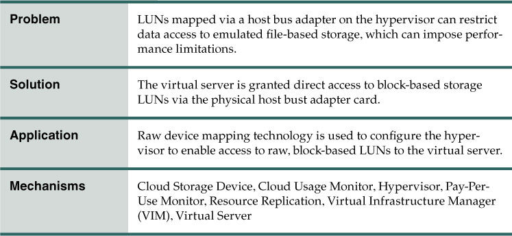
Problem
Storage LUNs are typically mapped via a host bus adapter (HBA) on the hypervisor, with the storage space emulated as file-based storage to virtual servers. Sometimes, however, virtual servers need direct access to RAW block-based storage. For example, when implementing a cluster and using the LUN as the shared cluster storage device between two virtual servers, access via an emulated adapter may be insufficient.
The following steps are shown in Figure 5.3:
1. The cloud storage device is installed and configured.
2. The LUNs’ mapping is defined so that each hypervisor has access to its own LUN and can also see the mapped LUNs.
3. The hypervisor shows the mapped LUNs to the virtual servers as normal file-based storage (and the virtual server uses it as such).

Solution
Virtual servers are granted direct access to block-based storage LUNs. Providing virtual servers with direct LUN access via a physical HBA card is effective because virtual servers that are part of the same cluster can use the LUN as a shared cluster volume for clustered databases. After implementing this solution, the required physical connectivity to the LUN and cloud storage device for the virtual servers is provided by the physical hosts.
Application
The LUNs are created and configured on the cloud storage device for LUN presentation to the hypervisors, which then needs to be configured using the raw device mapping to make the LUNs visible to the virtual servers as a block-based RAW SAN LUN, which is unformatted, un-partitioned storage. The LUN needs to be represented with a unique LUN ID for all of the virtual servers to use it as shared storage.
The application of the Direct LUN Access pattern by which virtual servers are given direct access to block-based storage LUNs is shown in Figures 5.4 and 5.5 in two parts.

Figure 5.4 A cloud architecture in which virtual servers are given direct access to block-based storage LUNs (Part I).

Figure 5.5 A cloud architecture in which virtual servers are given direct access to block-based storage LUNs (Part II).
1. The cloud storage device is installed and configured.
2. The required LUNs are created and presented to the hypervisors.
3. The hypervisors map the presented LUN directly to the virtual servers.
4. The virtual servers can see the LUNs as RAW block-based storage and can access them directly.
5. The virtual servers’ storage commands are received by the hypervisors.
6. The hypervisors process and forward the requests to the storage processor.
Mechanisms
• Cloud Storage Device – The cloud storage device mechanism provides virtual servers with direct access to the storage LUNs. Actual data is stored on the cloud storage device, which receives commands and requests from virtual servers and sends them to the physical disks for I/O read/write operations.
• Cloud Usage Monitor – This cloud usage monitor relates to the Direct LUN Access pattern in how it monitors and collects storage usage information that pertains to the direct usage of LUNs.
• Hypervisor – This pattern depends on the hypervisor to host and connect virtual servers to the cloud storage devices, and to forward virtual server requests. This mechanism enables virtual servers to send storage commands (typically SCSI commands) to the cloud storage device, after which the virtual servers can directly write on the cloud storage device instead of performing read/write operations on the virtual disk.
• Pay-Per-Use Monitor – The pay-per-use monitor may collect and separately classify service usage cost information via Direct LUN Access.
• Resource Replication – This mechanism may be involved with how virtual servers directly access block-based storage in replacement of file-based storage.
• Virtual Infrastructure Manager (VIM) – This mechanism enables virtual servers to be configured for direct access to specific LUNs that are visible to the hypervisor.
• Virtual Server – The virtual server is the mechanism to which this pattern is primarily applied.
Single Root I/O Virtualization

How can a single physical I/O device be virtualized and shared between multiple cloud service consumers?

Problem
When direct access to the I/O card is permitted via the application of the Direct I/O Access (169) pattern, it can introduce a potentially severe limitation (Figure 5.6). Multiple cloud service consumers may need to have access to the I/O card’s functionality, but it can only be accessed and used by one at any one time.

Figure 5.6 The Direct I/O Access (169) pattern is applied, which is sufficient for individual cloud service consumer access, but imposes a firm limitation should additional cloud service consumers require simultaneous access.
Solution
PNIC hardware that supports single root I/O virtualization (SRIOV) is used to abstract the I/O card’s features and present them to cloud service consumers separately.
PNIC hardware devices have two types of functionality:
• Physical Functionality (PF) – replicates the actual hardware’s capability and functionality
• Virtual Functionality (VF) – used to present multiple instances of the device to the hypervisor or virtual servers
Application
Application of this pattern requires the single root I/O virtualization feature to be enabled on the hardware I/O card. Note that the physical device will not be seen by the hypervisors or virtual servers when this feature is enabled. Instead, they will see the virtualized instances presented by the virtual functionality. The number of virtualized instances that can be created is dependent on a number of factors, such as hardware card type, vendor, model, and hypervisor.
The following steps are shown in Figure 5.7:
1. A physical NIC card that supports single root I/O virtualization is connected to a physical server that has the hypervisor installed and single root I/O virtualization feature enabled.
2. The device is abstracted into four instances, so the hypervisor sees four physical NICs.
3. Two instances of the NICs are attached to the virtual switch as physical uplinks.
4. Another uplink is assigned to a virtual machine to directly access the instance, similar to direct I/O access.

Figure 5.7 A physical NIC card attached to a physical server supports the application of the Single Root I/O Virtualization pattern.
One single hardware I/O card can be abstracted and used by multiple cloud service consumers. Note that any cloud service consumers that use abstracted instances are locked onto the host and cannot be moved to another host without requiring downtime.
Applying this pattern eliminates the limitation set by the Direct I/O Access (169) pattern and allows two or more I/O devices to be accessible to each virtual server. Also, the virtual servers that use single root I/O virtualized instances cannot be moved to another host via the application of the Non-Disruptive Service Relocation (159) pattern and use of the live migration mechanism, unless they are disconnected from the abstracted device instance.
Mechanisms
• Hypervisor – This mechanism establishes features to replicate physical I/O cards that support single root I/O virtualization into multiple virtual instances via the use of physical and virtual functions. Each virtual instance can be directly connected to a virtual server or virtual switch, or used by the hypervisor.
Cloud Storage Data at Rest Encryption

How can cloud providers securely store cloud consumer data on cloud storage devices?

Problem
Cloud storage devices can be accessed via a single physical storage array (Figure 5.8).

Solution
Data is secured on the physical disks using an encryption mechanism, so that unauthorized access to the physical hard disks does not compromise data security.
Application
An encryption mechanism supported by the physical storage arrays can be used to automatically encrypt and protect data that will be automatically decrypted when the data leaves the physical hard disks (Figure 5.9).

Figure 5.9 Data can be secured on physical disks by encrypting the data as it enters the physical storage array and decrypting data as it leaves the physical hard disks.
Using the same encryption key for multiple consumers or datasets in a multitenant cloud environment increases the security risk. Therefore, consider using shorter keys with simpler algorithms. A cryptographic key management system (CKMS) will be required to manage the keys. Depending on industry regulatory requirements, the cloud consumer may be required to directly manage the CKMS.
Mechanisms
• Cloud Storage Device – This mechanism represents the cloud storage devices that are affected by the application of this pattern.
• Cryptographic Key Management System (CKMS) – The CKMS is used to manage cryptographic keys.
• Encryption – This mechanism is used to encrypt and decrypt data traveling into or out of physical disks stored in a cloud environment.
Cloud Storage Data Lifecycle Management
How can data be stored and managed in a cloud environment based on a defined lifecycle?

Problem
Over time, datasets can lose value to organizations, but must still be retained for security, regulatory, or compliance requirements (Figure 5.10).
For example, the size of Cloud Consumer A’s data continues to increase, and they could be charged a cheaper price if it was moved to a less frequently accessed cloud storage device.
Solution
Implement a solution that automatically manages the data as well as moves data into different cloud storage devices based on a defined lifecycle. Outdated data can also be automatically deleted using this mechanism.
Application
Define the characteristics of the cloud storage devices in order to implement the data lifecycle management mechanism. A data transport mechanism should be implemented if the data requires migration to another cloud storage device. In combination, the mechanisms will manage the data at specific states in a defined lifecycle. The steps in applying this pattern are shown in Figure 5.11.

Figure 5.11 The steps in applying the Cloud Storage Data Lifecycle Management pattern are illustrated.
The cloud storage data aging management mechanism shown in Figure 5.12 can monitor and move data between Cloud Storage Devices A, B, and C based on a defined lifecycle from Consumer A of 6, 12, and 24 months, respectively.

Figure 5.12 The cloud storage data aging management mechanism can be used in applying this pattern to manage datasets based on predefined policies.
Mechanisms
• Cloud Storage Data Aging Management – This mechanism is used to define and assign data lifecycle policies and monitor the data throughout its lifecycle in order to initiate movement using the data transport mechanism where defined.
• Cloud Storage Device – Data stored on the cloud storage device is managed by the cloud storage data aging management mechanism and moved by the data transport mechanism.
• Data Transport – When data is moved between different cloud storage devices, this mechanism can automatically perform the migration when requested by the cloud storage data aging management mechanism.
Cloud Storage Data Management

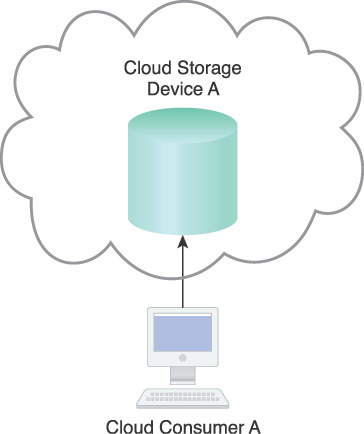
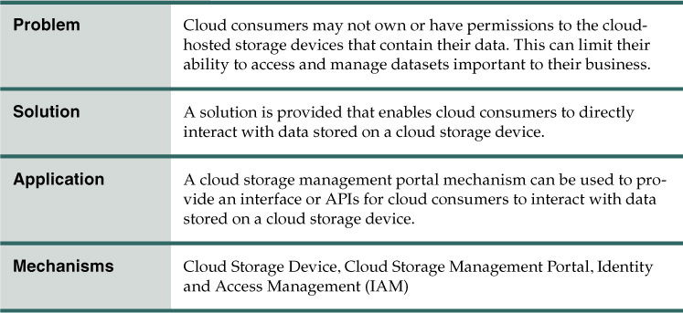
How can cloud consumers directly interact with data stored on a cloud storage device or provide access to other cloud consumers with appropriate permission levels?
Problem
Cloud consumers require a means of accessing and interacting with data stored in a cloud storage device. However, the fact that the cloud storage devices hosting their data may belong to third-party cloud providers can limit the extent to which cloud consumers can manage their own datasets (Figure 5.13).

Solution
Implement a mechanism capable of providing access to data stored on a cloud storage device for cloud consumers.
Application
As depicted in Figure 5.14, a cloud storage management portal mechanism can be used to provide interfaces and APIs in order for cloud consumers to interact with datasets and cloud storage devices.

Figure 5.14 A cloud storage management portal mechanism provides the access for cloud consumers to manage data stored on a cloud storage device.
This mechanism can be linked to a self-service portal and usage and administration portal so that newly requested cloud storage devices can be automatically discovered and added to the list of accessible cloud storage devices. Cloud authentication control can be used and accessed so that data is only provided to authorized cloud consumers.
Mechanisms
• Cloud Storage Device – This mechanism represents the cloud storage devices to which this pattern is primarily applied.
• Cloud Storage Management Portal – This mechanism is used to establish communication between cloud consumers and cloud storage devices, and also to provide the required level of access and control over data stored in a cloud storage device.
• Identity and Access Management (IAM) – To enforce a centralized or federated model of authentication and authorization, this mechanism is used to integrate a cloud storage management portal mechanism with IAM.
Cloud Storage Data Placement Compliance Check

How can cloud consumers ensure data that is stored on a cloud storage device is physically located in a region that meets required compliance policies?

Problem
There are a variety of corporate and governmental regulations that can require that certain types of data, especially private, confidential, or sensitive data, be physically located in the region native to the organization or in one of a list of approved regions. This was not a major concern with traditional data centers as their location was generally well known. However, when moving datasets into third-party cloud environments, organizations can lose the ability to govern storage devices to ensure compliance with such regulations. Furthermore, even if cloud storage devices initially are in compliance, cloud providers may opt to move them to other regions that may provide less expensive labor or infrastructure for their data centers, or perhaps for disaster recovery reasons (Figure 5.15).
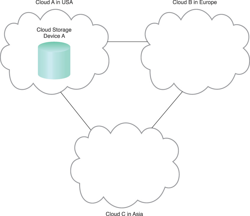
Figure 5.15 A cloud provider offers cloud storage in three regions. Initially the data may have been located in Cloud B, but has now been moved to Cloud A, unbeknownst to the cloud consumer.
Solution
A solution is implemented to ensure that a cloud storage device is only provisioned for use in a specific region, and that datasets stored on that cloud storage device will not be moved or copied into other regions.
Application
A cloud storage data placement auditor mechanism can be used to enforce policies defined by the cloud provider or cloud consumer on a specific dataset or cloud storage device. These policies are then attached to the dataset or cloud storage device and are automatically enforced.
The steps involved with the usage of this mechanism when applying this pattern are shown in Figure 5.16.
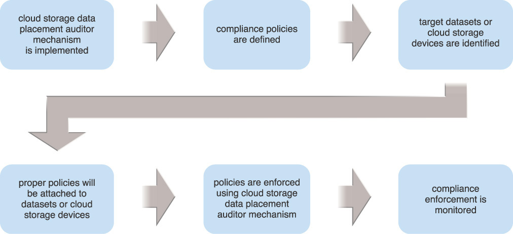
Figure 5.16 The steps in applying the Cloud Storage Data Placement Compliance Check pattern are illustrated.
A properly implemented cloud storage data placement auditor mechanism can prevent Cloud Storage Device A from being copied or replicated outside of the United States, as shown in Figure 5.17.

Figure 5.17 A cloud storage data placement auditor mechanism monitors and enforces policies on Cloud Storage Device A.
If this pattern is applied to prevent the replication of a dataset due to compliance requirements, integration between a resource replication mechanism and the cloud storage data placement auditor mechanism will be required.
Mechanisms
• Attestation Service – The attestation service receives the security status of the virtual servers from the TPM including location and is consulted when dispatching the workloads.
• Cloud Storage Data Placement Auditor – Monitors and enforces defined policies on a dataset or cloud storage device.
• Cloud Storage Device – This mechanism represents the cloud storage devices to which this pattern is primarily applied.
• Geotag – The geotag receptacle of the Trusted Platform Module (TPM) is provisioned with the compute platform geolocation.
• Resource Replication – To prevent dataset or cloud storage device replication as a result of compliance requirements, this mechanism can be integrated with the cloud storage data placement auditor mechanism.
• Trusted Platform Module (TPM) – The TPM is used as a trusted root for a secure boot of the physical and associated virtual servers and includes the geographic location of the servers and it reports the boot status to the trust attestation service.
Cloud Storage Device Masking

How can data stored on a cloud storage device be isolated to specific consumers?

Problem
Access to a cloud storage device may, by default, not be masked from unauthorized cloud consumers in a shared cloud environment. This can introduce inadvertent and malicious data access from unauthorized cloud consumers, cloud service consumers, or other neighboring IT resources.
Figure 5.18 illustrates Cloud Service Consumers A and B accessing respective cloud storage devices via a shared Physical Storage Array A.

Solution
A solution is implemented whereby a LUN masking mechanism is utilized to enforce policies at the physical storage array. This ensures that only authorized cloud service consumers can access the appropriate cloud storage device.
Application
A LUN masking mechanism can be used to isolate and control which consumer has access to which cloud storage device. Physical Server A and Hypervisor B will not have access to the cloud storage devices without being reviewed against LUN masking policies by the LUN masking mechanism. As a result, Hypervisor B cannot view or access Cloud Storage Devices A1 and A2, and Hypervisor A cannot view or access Cloud Storage Device B (Figure 5.19).

Many industry compliance regulations and best practices require an organization’s sensitive data to be encrypted when at rest. The cloud consumer can encrypt data and employ a key manager to manage the encryption keys. The organization may also need to control its own cryptographic key management system (CKMS) to meet some industry regulations and best practices.
Mechanisms
• Cloud Storage Device – This mechanism represents the cloud storage devices to which this pattern is primarily applied.
• Cryptographic Key Management System (CKMS) - A CKMS, controlled by the organization to meet industry regulations and best practices, provides a system for managing encryption keys.
• Encryption – Encryption of data at rest is used to meet some industry compliance regulations and best practices to protect from data breaches.
• LUN Masking – This mechanism enforces a set of access control policies at the physical storage layer that manage which cloud storage device is accessible to which cloud consumer.
Cloud Storage Device Path Masking

How can data stored on a cloud storage device be isolated to specific consumers via certain pathways?
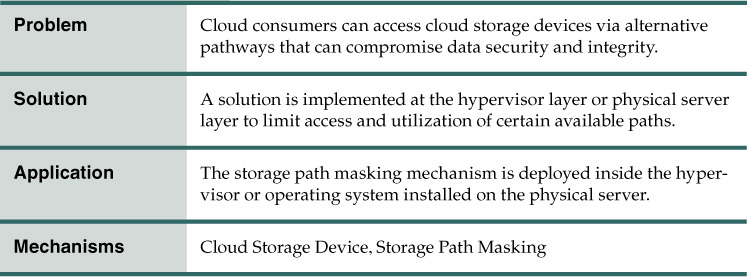
Problem
When multiple paths to a cloud storage device are available (such as when Multipath Resource Access (127) is applied), access to the cloud storage device by unauthorized cloud consumers becomes possible via the usage of alternative paths (Figure 5.20).

Figure 5.20 Redundancy of access to the cloud storage devices and physical storage device is implemented at Fabrics A and B, which connect each of the hypervisors to Physical Storage Array A. Cloud Consumer A and B can access both Fabric A and B via the two different dashed paths.
Solution
A solution is introduced to control and limit cloud consumer access to the utilization of certain available paths.
Application
The solution is implemented by using a storage path masking mechanism at the hypervisor layer or physical server layer. This limits access and utilization of available paths, as shown in Figure 5.21.

Figure 5.21 A storage path masking mechanism hides two of the previously visible paths to Hypervisor B.
In case all unmasked paths from a physical server or hypervisor to a physical storage become unavailable, the physical server or hypervisor cannot communicate with the cloud storage device and a manual process is necessary to unmask the available masked paths and resume service.
Mechanisms
• Cloud Storage Device – This mechanism represents the cloud storage devices to which this pattern is primarily applied.
• Storage Path Masking – This mechanism is used to mask or hide the available paths from physical servers running operating systems or hypervisors to unauthorized cloud consumers.
Cloud Storage Device Performance Enforcement
How can data with different performance characteristics be stored on a cloud storage device compliant with the performance requirements of each dataset?

Problem
A cloud consumer can contract three different cloud storage devices with varying storage performance characteristics, as follows:
• Cloud Storage Device A (Gold Tier)
• Cloud Storage Device B (Silver Tier)
• Cloud Storage Device C (Bronze Tier)
As depicted in Figure 5.22, a cloud consumer can copy different datasets onto a cloud, but needs to ensure that Datasets A, B, and C are stored on Cloud Storage Devices A, B, and C, respectively.

Figure 5.22 Different datasets with different performance requirements can be stored on different cloud storage devices with varying price points.
Solution
A solution is introduced to automatically manage data based on its performance requirements. This solution is further capable of moving data into different cloud storage devices when necessary. An alert can be raised to enforce policies that prevent datasets from being copied or moved to a different cloud storage device that does not meet performance requirements.
Application
A cloud storage device performance monitor mechanism can be implemented as a specialized type of SLA monitor to identify and classify the performance characteristics of cloud storage devices. A cloud provider would provide an API for cloud consumers to identify the performance characteristics of the different datasets.
By enforcing the performance requirements of each dataset, the cloud storage device performance monitor is able to generate an alert for a resource administrator to correct the performance mismatch or move the dataset to an appropriate cloud storage device.
Note that only some variations of this mechanism have the added ability to prevent data from being copied onto a cloud storage device that does not meet the defined performance requirements.
Mechanisms
• Cloud Storage Device – This mechanism represents the cloud storage devices to which this pattern is primarily applied.
• Cloud Storage Device Performance Monitor – This mechanism is used to check the performance characteristics defined for each dataset against the underlying cloud storage device or a destination cloud storage device for performance mismatch, which will then generate an alert or initiate the enforcement of a policy that prevents the dataset from being copied or moved.
Virtual Disk Splitting
How can a virtual disk be moved to another location that is either in the same cloud storage device or in a different cloud storage device?
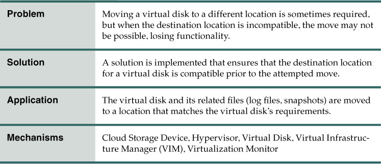
Problem
A virtual server may host an application that requires a different storage IOPS or throughput than other hosted applications. For instance, Figure 5.23 depicts Virtual Server A with three virtual disks, one of which is used to install a business-critical application that needs more storage I/O than the operating system. In this case, the virtual server needs to be moved to another storage tier or cloud storage device with greater I/O capacity.
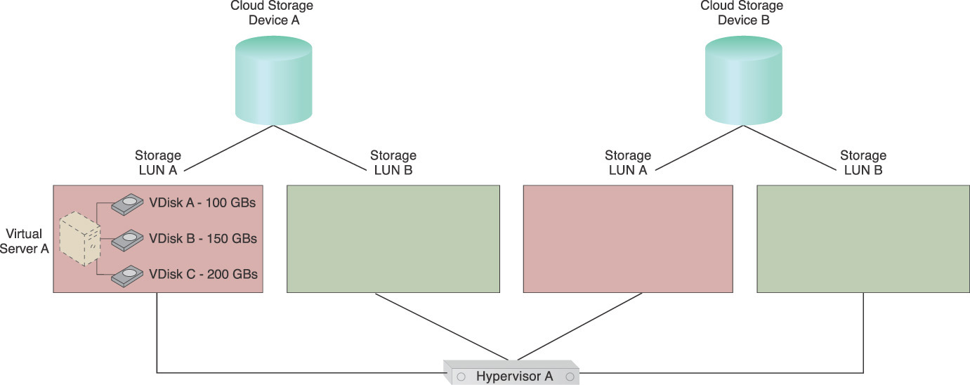
Figure 5.23 Virtual Server A has three VDisks named Virtual Disks A, B, and C. Virtual Disk C needs to be relocated to another storage location.
Two cloud storage devices are shown in Figure 5.23. Cloud Storage Device B has a greater performance capacity and incurs higher usage fees than Cloud Storage Device A. Each cloud storage device has multiple internal LUNs with different I/O capacities and costs. For simplicity, the higher the number of LUNs means the greater the I/O capacity.
Virtual Server A has its operating system installed on Virtual Disk A, local backup and log files stored on Virtual Disk B, and an I/O-intensive business application (Application A) installed on Virtual Disk C. Application A recently began experiencing degraded performance. An investigation reveals that the current I/O capacity has not been sufficient ever since the number of Application A’s cloud consumer requests began increasing.
If Virtual Server A is moved to either LUN B on Cloud Storage Device A or another LUN on Cloud Storage Device B, cloud consumers will be charged for the amount of space used for all three virtual disks. However, Virtual Disks A and B do not require as much I/O capacity as Virtual Disk C. A solution that allows individual virtual disks to be moved to a different storage LUN without causing any outages or service impact on Virtual Server A is required.
Solution
The virtual disks are separated from each other by placing them into storage that can sustain their required performance levels. Typically, all virtual disks are stored inside the same folder in which the virtual server was first stored at its creation. This solution uses the live VM migration mechanism to move individual virtual disks to a different storage location (with a higher or lower I/O capacity) while the virtual server is kept in operation. This migration process needs to be supported by the host hypervisor, so that the I/O can be redirected to the new storage location after migration has been completed.
The scenario that results after this pattern is applied is depicted in Figure 5.24.

Figure 5.24 Virtual Disk C has been migrated to LUN B by a live VM migration mechanism to accommodate Application A’s increasing requirements.
Application
In the example scenario shown in Figure 5.25, this pattern is applied to Virtual Server A. The virtual server is being forwarded requests from cloud consumers to use Application A on VDisk C. Figure 5.26 shows that the number of requests being sent for Application A has increased.


The increase in cloud consumer requests is creating a performance problem. Application A needs more I/O, a demand that cannot be accommodated by LUN A. This problem can occur even if the number of cloud consumer requests has not increased, as long as the other virtual servers being hosted on the same LUN are consuming most of the I/O.
The steps involved in applying this pattern are illustrated in Figures 5.27 and 5.28.
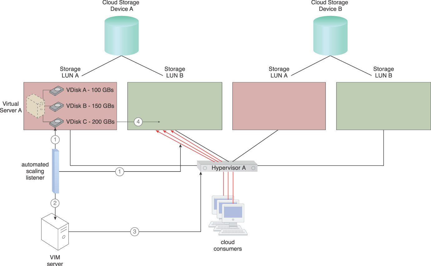

1. The automated scaling listener mechanism monitors the number of requests and measures the available I/O for VDisk C.
2. When the available I/O or number of requests reaches its pre-defined threshold, the VIM server receives a signal to move VDisk C.
3. The VIM server signals Hypervisor A to initiate moving VDisk C to LUN B on Cloud Storage Device A.
4. Hypervisor A starts to create a synchronized copy of VDisk C on LUN B. Depending on the environment’s structure, the hypervisor may offload this task to the cloud storage device to be performed at the storage layer. Otherwise, the hypervisor creates the copy via the network or storage network.
5. The synchronized copy is completed.
6. The cloud consumer requests are forwarded to VDisk C on LUN B and the original copy of VDisk C is deleted from LUN A.
Applying this pattern allows each of the applications or operating systems that are installed on a virtual disk to be hosted on a location that can accommodate their individual performance and bandwidth requirements.
Mechanisms
• Cloud Storage Device – This mechanism is used to host virtual server folders and their relevant files.
• Hypervisor – This mechanism is used to host virtual servers, and is also responsible for moving virtual disks between cloud storage devices based on pre-defined rules or thresholds.
• Virtual Disk – The virtual disk contains the virtual server’s operating system, applications and data, and cloud consumer data, and can move between cloud storage devices to meet its own space or performance requirements.
• Virtual Infrastructure Manager (VIM) – This mechanism is used to configure thresholds and policies that dictate which actions the hypervisor should take. The VIM also moves virtual disks from one cloud storage device to another, and is used to manually initiate the disk splitting process.
• Virtualization Monitor – This mechanism is used to monitor disk IOPS and free disk space utilization, as well as to help make predictions that can improve disk-splitting policies and virtual disk placements.
Sub-LUN Tiering
How can a subset of data stored inside a LUN be moved without having to migrate the entire LUN?

Problem
Datasets can have specific performance requirements that separate them from other subsets of data stored within a LUN. When such requirements come about, it may be necessary for such datasets to be moved to a location that can fulfill the desired performance requirements.
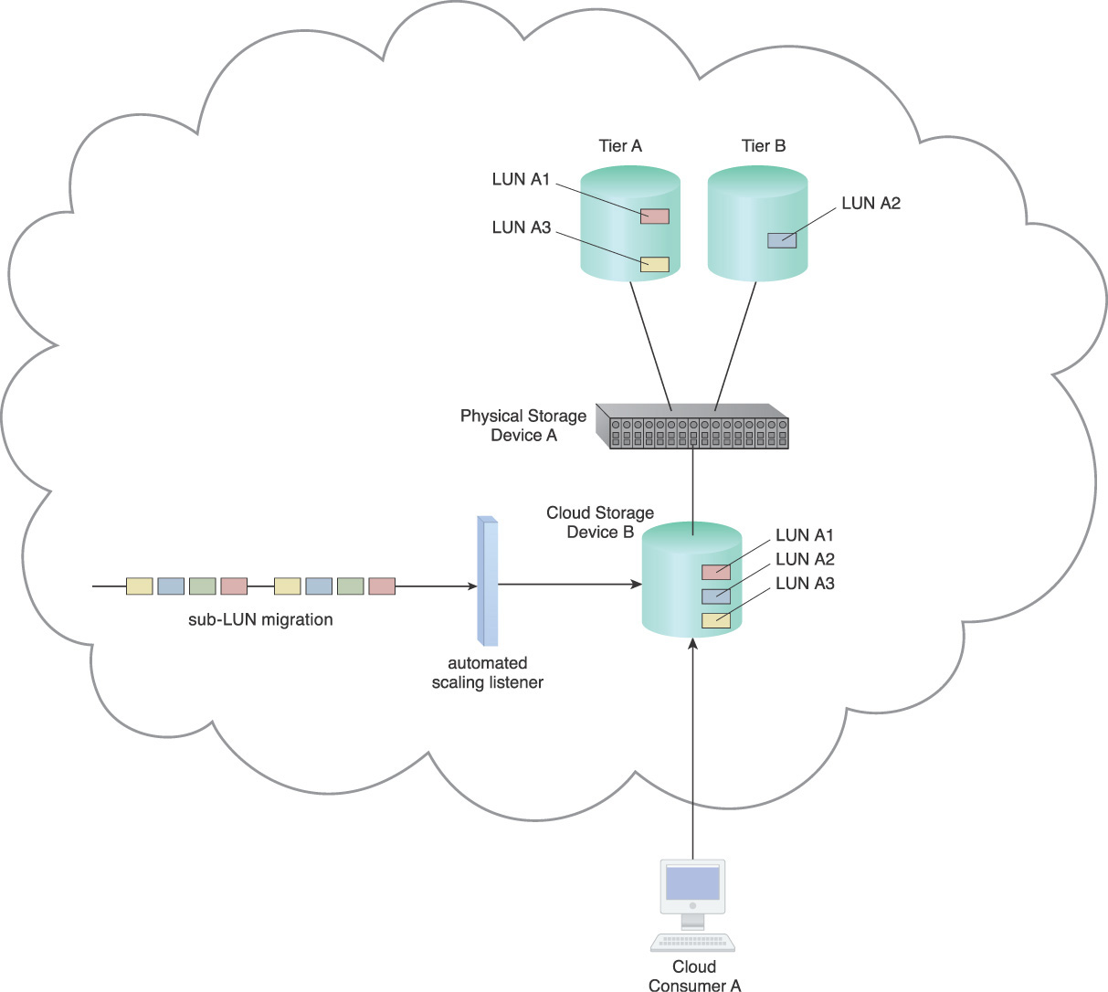
For example, in Figure 5.29 LUN A is presented to Cloud Consumer A as Cloud Storage Device B with three different datasets. However, Dataset A2 needs to be placed on a higher performance storage tier without having to move LUN A. Moving the entire LUN will result in unnecessary charges for storage space utilization.

Solution
The solution has the intelligence necessary to check for locations that are compatible with dataset performance requirements and can further move datasets to those locations.
Application
Data can be selectively moved to another tier via a sub-LUN migration mechanism that is activated by an automated scaling listener mechanism. The automated scaling listener mechanism can compare required performance levels against actual performance levels and initiate migration of data via a sub-LUN migration mechanism when necessary (Figure 5.30).

Figure 5.30 An automated scaling listener mechanism is connected to a sub-LUN migration mechanism after applying the Sub-LUN Tiering pattern.
When migration is required, the sub-LUN migration mechanism can selectively migrate the dataset to another performance tier or cloud storage device (Figure 5.31).
Mechanisms
• Automated Scaling Listener – This mechanism actively monitors the performance of a LUN and datasets in order to initiate migration where necessary.
• Cloud Storage Device – The cloud storage device is a common IT resource that may require the creation of an alternative path in order to remain accessible by solutions that rely on data access.
• Sub-LUN Migration – This mechanism is used to migrate required sub LUNs or datasets to different tiers or cloud storage devices.
RAID-Based Data Placement

How can data be stored on a RAID level that matches its required performance and protection levels?

Problem
Cloud storage devices are provisioned with different underlying and back-end RAID levels. A cloud provider will charge cloud consumers different prices based on the features, performance, and data protection levels required. Data copied to a cloud storage device needs to be stored with a required protection level (Figure 5.32).

Figure 5.32 Consumer A will store data in a cloud storage device according to the RAID level that best satisfies its performance and data protection requirements.
Solution
An interface to the cloud consumer can provide information on the underlying RAID level of cloud storage devices via a RAID identifier mechanism that interacts directly with the cloud storage management portal mechanism.
Application
A RAID identifier mechanism is utilized to inform cloud consumers of the underlying RAID level for a requested cloud storage device via the cloud storage management portal mechanism, which allows the consumer to interact with a cloud storage device in order to copy or move data to and from the cloud without compromising the security of other cloud consumer’s data (Figure 5.33).

Figure 5.33 A RAID-level identifier mechanism will use the cloud storage management portal mechanism to return information on the specifics of the cloud storage devices to Cloud Consumer A.
Cloud consumers can select which cloud storage device best fulfills a set of requirements given the information provided by the RAID identifier mechanism.
Mechanisms
• Cloud Storage Device – This is the mechanism to which this pattern is primarily applied.
• Cloud Storage Management Portal – A cloud storage management portal mechanism allows the cloud consumer to view the RAID level of each cloud storage device and copy data into an appropriate cloud storage device.
• RAID-level Identifier – A RAID-level identifier identifies the underlying RAID level of each cloud storage device in order to forward the information to the cloud storage management portal mechanism.
IP Storage Isolation

How can IP storage be secured while using the same communication layer and channel as other networking traffic?

Problem
Storage traffic shares the same underlying network infrastructure as network traffic and must ensure security against unauthorized access to Cloud Storage Devices A and B.
Solution
A solution is introduced to ensure that isolation and security are enforced before data is returned to cloud consumers. In the scenario depicted in Figure 5.34, when the data leaves a cloud storage device and travels into the network for Hypervisors A or B, security is automatically enforced to ensure data travels to the appropriate cloud consumer.

Figure 5.34 Virtual Server A and B require access to Cloud Storage Devices A and B without viewing or accessing each other’s data.
Application
A LUN masking mechanism can be used between IP storage devices and the respective cloud consumers to implement the appropriate isolation. Isolation can be used at OSI Layer 2 to ensure cloud consumers communicate over a dedicated OSI Layer 2 network, while other cloud consumers can exist in a separate OSI Layer 2 domain. Quality of service mechanisms can ensure the required levels of network resources are available for IP storage.
Some storage vendors provide the APIs for storage resource administrators to interface with the cloud storage device and manually configure policies or automate the policy configuration. A standalone management interface can define the policies so that servers can only see and access the LUNs presented.
A storage path masking mechanism can establish concurrent communication over the multiple available paths, while hiding some of the paths from the systems or applications (in Figure 5.34, this mechanism operates at Physical Switch A). A RAID-level identifier mechanism can be used to identify the RAID level of cloud storage devices and forward the information to a cloud storage management portal mechanism via provided APIs or SDKs. If no API or SDK is provided, then cloud storage resource administrators can manually populate the information by using available features and options, such as inventory tags or defined attributes, which attribute a value according to the RAID level of the cloud storage device.
Mechanisms
• Cloud Storage Management Portal – This mechanism is used to enable cloud consumers to interact with the data stored on cloud storage devices and restrict access based on defined policies.
• LUN Masking – This mechanism can manage which cloud consumers have access to view and interact with specific LUNs via available pathways.
• RAID-level Identifier – This mechanism can ensure data is stored in a cloud storage device with defined requirements that are managed by the cloud storage management portal mechanism.
• Storage Path Masking – This mechanism can isolate cloud storage devices by masking otherwise available pathways from cloud consumers to the cloud storage devices.
• Virtual Network – This mechanism is used as the network between a cloud storage device and a physical storage device or between cloud storage devices.