
Chapter 9. Network Security, Identity & Access Management and Trust Assurance Patterns

Secure On-Premise Internet Access
Secure External Cloud Connection
Secure Connection for Scaled VMs
Cloud Denial-of-Service Protection
Cloud Traffic Hijacking Protection
Automatically Defined Perimeter
Federated Cloud Authentication
Collaborative Monitoring and Logging
Threat Intelligence Processing
This chapter acts as a continuation of Chapter 8 in that it continues to focus on cloud security architectures and solutions. This time, the areas covered are network security with an emphasis on external connectivity issues, the management of identities and access levels, and patterns that are applied to establish trust boundaries and characteristics.
Problem
The Internet connection is the first location where consumer and attacker need to be identified and separated as it is the primary point of entry for external attackers. Figure 9.1 provides an example where outbound interactions are initiated by consumers from within the enterprise that allow bi-directional data flow. This region contains the highest level of uncertainty because the untrusted network and trusted network are both present. Probes and brute force authentication attacks targeting infrastructure devices are common, and poorly designed networks will unintentionally allow enumeration of network accounts in credential stores.
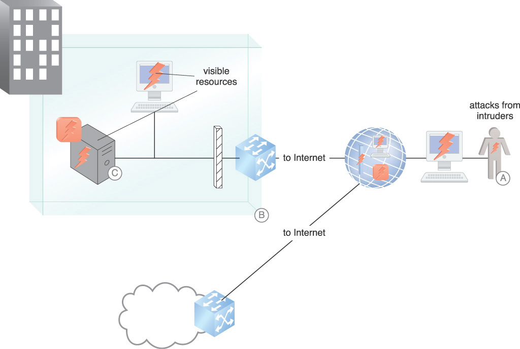
Figure 9.1 shows the following threats to an enclave connected to the Internet:
A. Man-in-the-middle (MITM), session hijacking, cross-site scripting (XSS), malicious DNS attacks and distributed denial-of-service (DDoS) attacks are examples of the types of attacks that can be mounted. They are executed against any surface that is revealed to the Internet. One goal of these attacks is to install malware that further exploits enclave vulnerabilities.
B. Other attacks that can be encountered are malicious DNS responses that deceive internal components into interacting with malicious entities on the Internet or allowing botnet command and control server interactions with compromised internal hosts. DNS tunneling is often used to bypass access controls.
C. An example of malware is a botnet zombie that is installed on a visible resource and takes instructions from a remote attacker. Malware is installed on visible resources.
Solution
Secure network segmentation is introduced to protect internal networks from the Internet, starting with an external Internet-facing firewall. In Figure 9.2, firewalls and network address translation (NAT) provide protection from Internet intruders as follows:
A. Firewalled subnets provide segmentation to separate peered networks, participating in a DMZ architecture that protects all internal and external connections. The network segmentation architecture allows for mitigations to be put in place to combat the evolving taxonomy of Internet-based attacks.
B. For inbound access control, firewalls prevent attacks from the Internet. For outbound access control, the firewall allows authorized outbound interactions. For both inbound and outbound traffic, NAT provides information hiding capabilities.
C. To establish connection to cloud resources, VPNs are employed. This lays the groundwork to create cryptographically protected communication between cloud resources and on-premise protected resources.
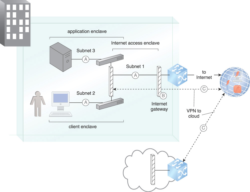
Figure 9.2 An example of subnet segmentation, firewalls, and NAT provider protection from Internet intruders.
Application
A security architecture is created using subnets that provide a foundation for multiple security services across the enclaves. Access cascades between enclaves through the firewalls so that any enclave can only connect to adjacent enclaves with the proper permissions. The architecture can be expanded to provide multiple enclaves for requirements such as infrastructure services, for example DNS and subsystems that are used by outward-facing Web services. Each function of the Web service can be isolated into a separate enclave. The enclave segmentation lays the groundwork to establish mitigations for various types of attacks. The concept of an application delivery controller (ADC) is used where a number of protection mechanisms are combined in a network device. Figure 9.3 illustrates mechanisms and their relationships in implementing the pattern.
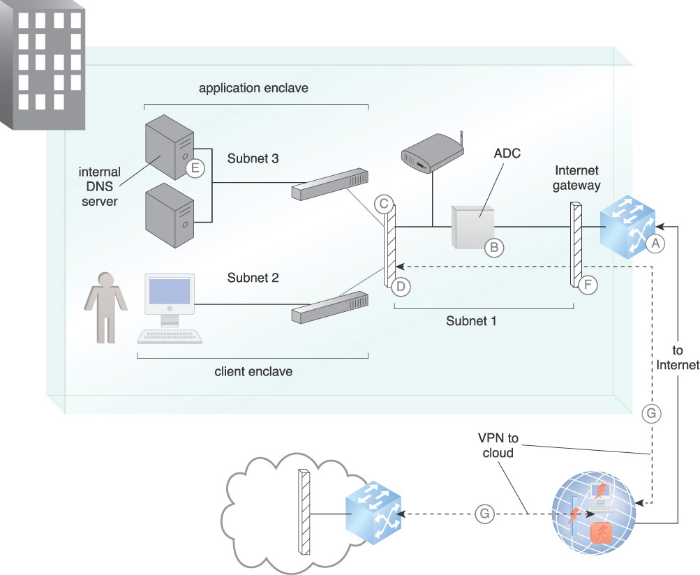
A. Whitelists and blacklists are established and maintained to prevent users from interacting with known or suspected malicious entities and to protect internal assets from attacks. Black hole is used to provide protection against DDoS attacks.
B. A DMZ ADC acting as a security gateway performs a dual role in protecting against attacks and detecting anomalous information flow from within the DMZ. It provides application security and data loss protection (DLP), and can prevent data leakage and provide application level protection.
Proxies and TLS accelerators are hosted in the Internet access enclave. They terminate encrypted TLS sessions so that the traffic can be monitored within the enclaves. Since encryption without inspection hides exfiltration occurring within enclaves, a TLS proxy that consists of a TLS offloading engine is incorporated. This engine can be accelerated using a hardware security module (HSM) with cryptographic acceleration that will accept inbound TLS traffic from consumers and decrypt it. This provides elimination of TLS processing on servers and support for application layer functions.
C. The firewalls are configured to perform stateful packet inspection of network traffic after the TLS proxy decrypts the communication. This allows inspection of unencrypted traffic as it traverses other enclaves.
D. The security architecture is expanded to provide other security services including network IDPS, application and database firewalling, in-line malware scanning, and load balancing. IDPS devices are necessary to safeguard the infrastructure as well as to examine the evolving taxonomy of Internet-based attacks.
For pre-infection threat prevention, IDPS blocks exploitation of known application vulnerabilities. Anti-malware functions block exploitation of data-driven application vulnerabilities. The IDPS enforces protocols and data compliance. Post-infection threat prevention detects and blocks interactions with bot command and control servers. IDPS controls block leakage of sensitive data to destinations outside of the organization.
E. An internal DNS is configured to protect against DNS attacks. Clients and servers must point to trusted DNS servers within the enclave. The enclave DNS servers then connect to authoritative servers on the Internet. DNS servers within the network application enclave as well as all DNS clients within the other enclaves are not permitted direct Internet access for names resolution. For queries of external domains, clients and servers must perform lookups through the enclave DNS servers.
F. The Internet access enclave functions as a DMZ. For inbound access control, firewalls prevent attacks from the Internet. For outbound access control, the firewall allows authorized outbound interactions. Whitelist/blacklist prevents access to known malicious sites and use of applications associated with malware and data loss. For both inbound and outbound traffic, NAT provides information hiding.
G. With the on-premise enclaves protected, required connection to cloud resources can be accomplished with VPNs. These VPNs are routed between protected on-premise enclaves and cloud resources for administration.
Segmentation of enclaves places web, mobile applications, and clients in separate enclaves. In practice, there should be multiple peered enclaves. For example, infrastructure such as DNS servers and database servers should be in separate enclaves that are connected by separate firewalls. Any peering relationship (routing protocols, VPN, LDAP, etc.) must be mutually authenticated prior to establishing a trusted connection. This control helps defeat attack sources masquerading as trusted peers. Integrity checking must also be in place to defeat man-in-the-middle attacks. Identity and access management (IAM) must be implemented with separation of duties (SOD) for administrators.
The standalone Internet-facing firewall is intended to serve as a buffer between the Internet access enclave and the remaining enclaves within the peered segment. This approach prevents resource exhaustion attacks that target the Internet-facing firewall. External management and non-public information exposure are disabled on the outside interfaces. Access control lists (ACLs) are created with permit statements that match security policy and align with business requirements. This approach applies to both inbound and outbound traffic. ACLs must end with an explicit deny with logging enabled for dropped connections. An automatic routing black hole is implemented on the routers and firewall, and black hole routes are used to prevent traffic from crossing network segments. For example, a black hole route implemented on the border router is used to prevent a DDoS attack.
Logging of denied packets provides valuable insight including common attack vectors, taxonomies, and firewall administrator ACL change errors. This data is also valuable for effective data and event correlation across all network and security devices. Logging of the permitted traffic is a commonly accepted practice.
Data leakage prevention includes network-related information like internal IP addresses and routing tables. ICMP and other non-required vulnerable protocols are disabled to defeat reconnaissance efforts by attackers. All network devices must have a common authoritative time source via Network Time Protocol (NTP). This provides credibility for logging and data correlation.
An impact of using a suite of security mechanisms, besides the cost and complexity, is the critical need for automation. Security design should always first consider automation that includes incorporation of a security information and event management (SIEM) system to support incident alerting and auditing.
Mechanisms
• Application Delivery Controller (ADC) – The ADC concept is applied by combining security functions on some security devices.
• Domain Name Service (DNS) – DNS is secured against attacks by installing an internal DNS in a protected enclave.
• Hardware Security Module (HSM) — An HSM provides cryptograph acceleration for high cryptographic processing workload requirements.
• Intrusion Detection and Prevention System (IDPS) – IDPSs are installed as part of the ADC concept.
• Security Information and Event Management (SIEM) System – SIEM is used for alerting and auditing and to support coordination of the inputs from the various security mechanisms.
• Virtual Private Network (VPN) – The VPN is used to securely connect the on-premise resources to the cloud resources.
Secure External Cloud Connection
How can a cloud network establish a secure connection with on-premise IT resources?
Problem
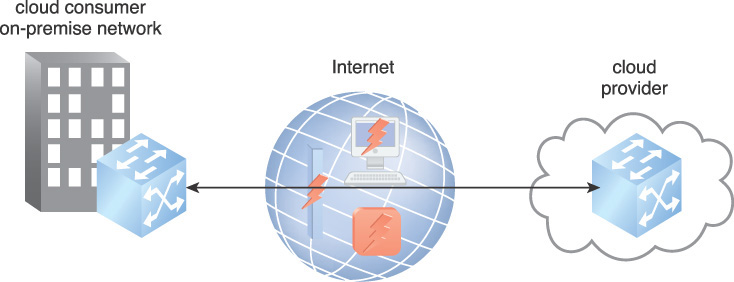
Federal regulations, such as the Sarbanes-Oxley Act (SOX) and the Health Insurance Portability and Accountability Act (HIPAA) and laws and industry mandates such as the Payment Card Industry Data Security Standard (PCI DSS), often require organizations to maintain some processing and storage on-premise. Some on-premise IT capability may be maintained for continuity of operations and disaster recovery. The connection to two geographically dispersed locations combined with the complexities of the cloud poses connection security challenges. Figure 9.4 illustrates the security situation for a single cloud provider. The connection needs to protect against man-in-the-middle, snooping, and other attacks.
Solution
A cloud consumer gateway (CCG) is established on the cloud consumer side and connected to a virtual private cloud (VPC) using encryption. The encrypted connection is illustrated in Figure 9.5.
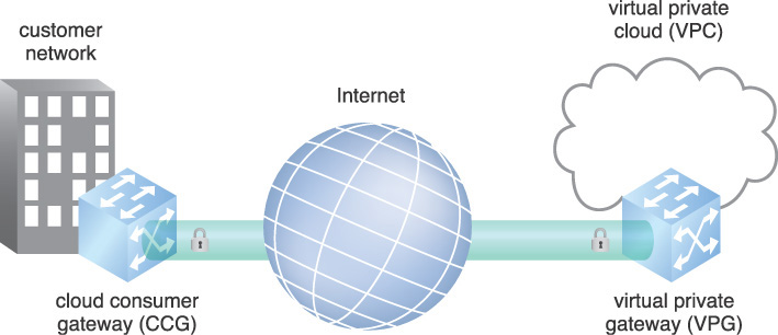
Figure 9.5 A secure connection is established between the cloud consumer network and virtual private cloud.
Application
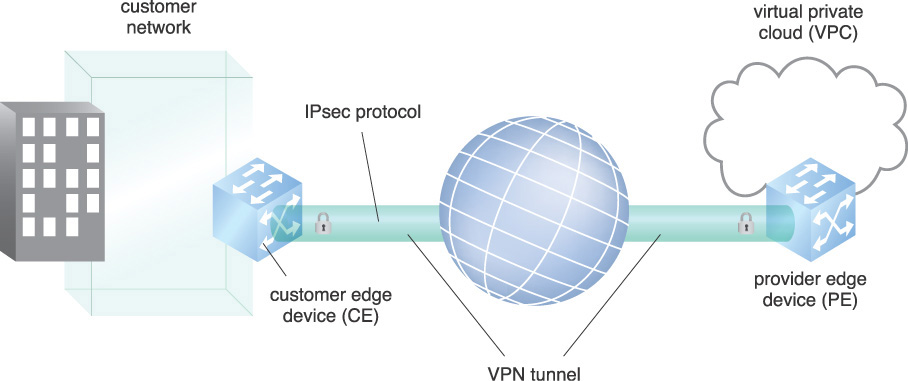
The VPG is connected to the CCG via a virtual private network (VPN). The VPN extends the on-premise private network across the Internet or other public network, or wide area network (WAN). The VPN securely connects geographically separated offices of an organization, extending and creating one network. A customer edge (CE) device is located at the edge of the cloud consumer’s network, providing access to the VPN. A provider edge (PE) device is a device or set of devices at the edge of the cloud provider network that connects to consumer networks through CE devices and maintains the VPN state.
VPNs ensure confidentiality and integrity of communication. They employ authentication mechanisms to ensure that the communication parties are who they claim to be, encryption to ensure confidentiality and integrity of data, and optionally, compression for efficient use of bandwidth.
The IPsec Security Protocol is a suite of protocols developed by the Internet Engineering Task Force (IETF) that provides standards for encryption, authentication, and compression at the network level. In Figure 9.6, a CE device is connected to a PE device, creating a VPN tunnel using the IPsec Protocol standard.
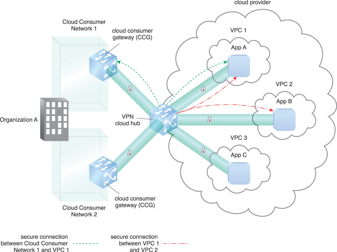
In cloud computing, there are multiple configurations and network topologies that can be applied to this pattern. The pattern assumes a hardware device at each network, establishing the VPN. Software VPNs can be established within VMs or within any combination of VMs and physical devices. Another option for connection is the VPN hub-and-spoke with a VPN cloud hub. The cloud hub is a hub-and-spoke model that connects multiple branch offices and existing Internet connections with a VPC or multiple VPCs.
Figure 9.7 shows the VPN cloud hub architecture with connections to multiple VPCs. The dashed lines indicate the network being routed over their VPN connections between sites. One secure connection (A) is shown between Cloud Consumer Network 1 and VPC 1. A second connection (B) is shown between VPC 1 and VPC 2.
The major impact of establishing a VPN is networking and the security and management of encryption keys. The Cloud Key Management (444) pattern provides insight to these issues, as well as viable solutions. The network topology is complex, requiring concentrated focus from network designers and implementers and an understanding of routing protocols such as the Border Gateway Protocol (BGP), Open Shortest Path First (OSPF), and the Enhanced Interior Gateway Routing Protocol (EIGRP), which allows routes between sites connected by site-to-site VPN connections to be automatically learned. Security policy needs to be developed in regards to key management systems, and assurance level of the encryption needs to be determined based on the data sensitivity and risk of compromise. Once the VPNs are established, they must be monitored and must have automatic recovery provisioning when outages are encountered.
Mechanisms
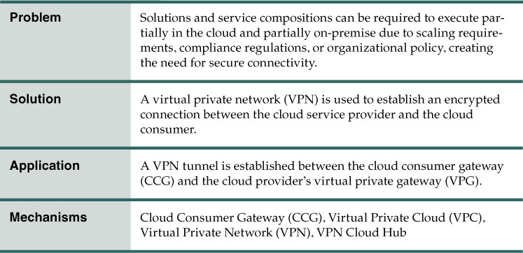
• Cloud Consumer Gateway (CCG) – The CCG is used by the cloud provider to terminate a cloud consumer’s VPN.
• Virtual Private Cloud (VPC) – The VPC is used for normal processing while on-premise resources are used to house high value corporate data.
• Virtual Private Network (VPN) – The VPN is the selected method for encrypting the data in-transit.
• VPN Cloud Hub – The VPN cloud hub is used to consolidate the VPN connection from the on-premise network, as well as multiple connections to VPCs.
Secure Connection for Scaled VMs
How can connections be scaled to protect dynamically scaled VMs in a way that mitigates cloud provider lock-in?
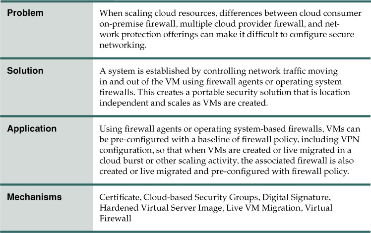
Problem
Firewall rules are often managed in a hierarchical manner based on physical location, logical location of the assets on subnets, and functions of the server requiring network services. Within a particular firewall, rules are normally organized based on the logical architecture of the network. Policy grouping typically includes traffic entering the DMZ, traffic leaving the DMZ, and traffic entering or leaving the internal network, plus other network protection requirements. These policies can have hundreds of rules, including firewall virtual private network (VPN) configurations.
When VMs are created, isolation and security zones can be established through the use of firewalls, routers, switches, intrusion detection and prevention system (IDPS) devices, and other physical devices on the network in virtualization environments in order to meet security needs. As VMs are moved, the policies and required infrastructure need to move with them. However, the VMs are ephemeral in that hosts and IPs are constantly being created for the requested workload and removed when the resources are no longer needed.
Firewalls can become an issue during virtual machine replication, when either scaling in a homogeneous firewall environment or bursting into a heterogeneous firewall environment. Under these circumstances, firewall security must be handled quickly and automatically, as scaling or a burst is usually due to the immediate need for more processing resources.
Multiple firewall vendors’ products can also become an issue. The consumer organization may be using one kind of firewall internally, but their cloud provider may not be supporting it. A second provider may be using another firewall solution. This can create the requirement to manage firewall policies across multiple vendor interfaces.
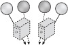
Figure 9.8 shows two consumer business processes being protected by a network or subnet-oriented firewall. There is a requirement to burst out to the cloud and at the same time maintain firewall protection. The issue lies in how to quickly configure the cloud firewall system to maintain the current level of protection.
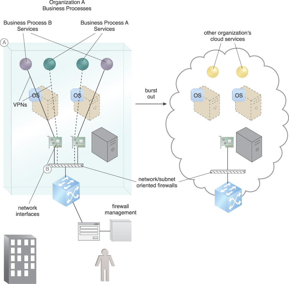
Figure 9.8 Organization A’s cloud consumer needs to scale out from on-premise and may also need to scale from one cloud to another (A). Meanwhile, the firewall connectivity and security need to be managed in realtime (B).
Solution
A system is established that can use a single firewall policy, which is enforced regardless of execution location or firewall offering by a cloud provider. This can be done by using the firewall built into each operating system or by virtual firewall agents dedicated to each VM. By defining the rules within the virtual host-based firewall or firewall agents, protection is not dependent on location, and the rules can scale as VMs are created. Firewall rules can be set once, and no longer need to be updated if the server switches locations.
Figure 9.9 shows OS-level firewall VPNs providing network security as follows:
A. An OS or virtual agent firewall connects Business Process A’s services via a VPN.
B. An OS or virtual agent firewall connects Business Process B’s services via a VPN.
C. They are all managed by a policy-driven firewall management system capable of managing multiple OS type firewalls or firewall agents.
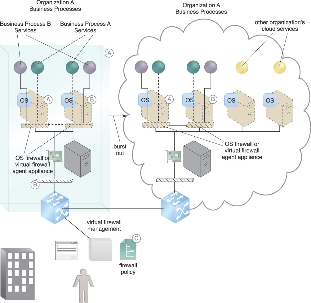
Figure 9.9 Organization A’s services are burst out into a cloud, either by live migration or spin up from a hardened virtual server image. Virtual machine replication can be used to live migrate a VM from an on-premise configuration in a burst out to the cloud.
When services are burst into a cloud, the firewalls are included with the OS and are pre-configured to continue operations.
Application
Secure network endpoints are created using mutual authentication. With a virtual private network (VPN), each endpoint device, such as a firewall, must have a certificate to authenticate itself. Each endpoint authenticates itself to the other by proving that it has the corresponding private key using a cryptographic exchange. For a high degree of key management security, the key can be stored in a hardware security module (HSM) so it cannot be stolen without physical access to the HSM. In addition, the management of the HSM can be distributed among a number of administrators for a separation of duties so that no one person can compromise the keys.
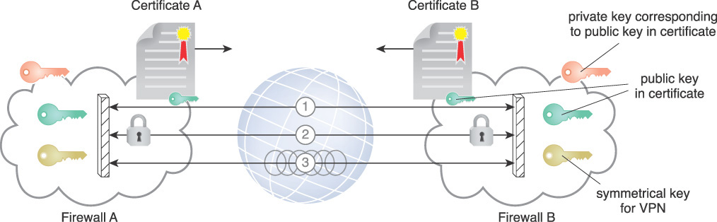
Figure 9.10 summarizes the steps to create a VPN between two network endpoint devices:
1. Firewalls exchange certificates to authenticate and provide each other with their public key.
2. Each firewall creates a shared secret from their private key and other peers’ public key. They each derive the Diffie-Hellman (DH) key, which is used to exchange material that will be used to derive a symmetric key.
3. Each firewall creates its own corresponding symmetrical key from the DH key and the material exchanges and sets up a VPN.
Organizations should create policies that move network associations required for virtual machines along with the virtual machines themselves. Virtualization-aware solutions that can manage network security policies and work with the hypervisor for added visibility and control need to be implemented. Hardened master VM template images used to create new servers must include the host firewall and firewall policy. Alternately, virtual firewall agents can be allocated to each VM and included in the image template. The template should use digital signatures to ensure integrity, assuming a proper signature validation is performed. As images are deployed on new servers, they inherit the parent image’s latest security policies. Service security from a firewall standpoint becomes automatic when cloud bursting or scaling. As the IP address changes, other location-dependent factors such as network security automatically change configurations or are assisted by an administrator.
Implications for using OS-based firewalls include the potential of lowering costs since those firewalls are included in the OS pricing. This pattern is vendor independent, an impact of which is that a third party or combination of third party components is likely required to implement the pattern. If firewall agents are used, there will be license costs as well as the need for a management console.
For security reasons, it is important to monitor network traffic and alert to anomalies. The organization should not use virtual networking unless a coordinated virtual network monitoring system is in place. Otherwise it is not possible to monitor virtual networking since it does not traverse the network layer.
Mechanisms
• Certificate – Certificates are used for mutual authentication of VPN endpoints.
• Cloud-based Security Groups – Cloud-based security groups support resource scaling referencing firewall policy.
• Digital Signature – The digital signature is used to establish and verify the integrity of VM image templates.
• Hardened Virtual Server Image – Hardened virtual server images are established to include pre-configured virtual firewalls for scaling.
• Live VM Migration – Enables migration of virtual servers from one location in a burst out without service interruption.
• Virtual Firewall – A virtual firewall appliance (virtual software) is paired with each VM to establish a VPN that is easily relocated along with the associated services it connects and protects.
Cloud Denial-of-Service Protection

How can cloud services be protected against denial-of-service attacks?
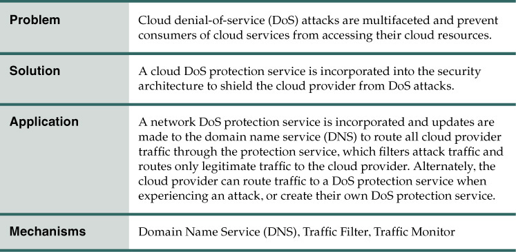
Problem
There are three categories of DoS attacks: volume-based attacks, protocol attacks, and application layer attacks. A volume-based attack is when a DoS forces a cloud victim to use overwhelming amounts of network bandwidth. This causes unsupportable network usage, leaving the cloud services without network resources and causing non-responsiveness. These DoS attacks include distributed denial-of-service (DDoS) and distributed reflector denial-of-service (DRDoS). The attacks focus on multiple layers of the networking stack. Volume-based attacks include UDP floods, ICMP floods, and other spoofed-packet floods.
A DNS reflection attack is another type of volume-based attack whereby the attacker sends a request for a large DNS zone file with the source IP address spoofed as the IP address of the intended victim. The file is sent to a large number of open DNS resolvers who then respond to the request, sending the large DNS zone answer to the IP address of the intended victim. The attacker’s requests themselves are only a fraction of the size of the responses, allowing the attacker to amplify their attack to many times the size of the bandwidth resources they control. The goal of the attack is to saturate the bandwidth of the attacked site, and the magnitude is measured in bits per second (Bps).
An example of a transport layer volume-based attack is an acknowledge (ACK) attack. A server initiating a TCP session first sends a synchronize (SYN) request to the receiving server. The receiving server responds with an ACK, after which data can be exchanged. In an ACK reflection attack, the attacker sends large amounts of SYN packets to servers with spoofed source IP addresses pointing to the intended victim. The servers then respond to the victim’s IP with an ACK, creating the attack. Like DNS reflection attacks, ACK attacks disguise the source of the attack, making it appear to come from legitimate servers. The goal of the volume-based attack is to saturate the bandwidth of the attacked site, and the magnitude is measured in bits per second (Bps).
Protocol attacks include SYN floods, fragmented packet attacks, Ping of Death, Smurf DDoS, and others. This type of attack consumes actual server resources or those of intermediate communication equipment, such as firewalls and load balancers, and is measured in packets per second. As an example, in a Smurf attack, an attacker will spoof the source address of the Internet Control Message Protocol (ICMP) ping packet and send a broadcast to all computers on that network. ICMP is a connectionless protocol commonly used for diagnostic purposes that does not use any port number and works in the network layer. If networking devices do not filter this traffic, they are broadcast to all computers in the network. Because ping does not include a handshake, the destination has no means of verifying if the source IP is legitimate. The router receives the request and passes it on to all the devices that sit behind it. Each of these devices then responds back to the ping. The attacker is able to amplify the attack by a multiple equal to the number of devices behind the router.
Application layer attacks include attacks on application vulnerabilities. Comprised of seemingly legitimate and innocent requests, the goal of these attacks is to crash the application, such as a Web server. The magnitude is measured in requests per second. Exhausting a Web server’s thread pool is one example of an application layer attack. Another is the low-rate denial-of-service (LDoS) attacks that can tie up a Web server.
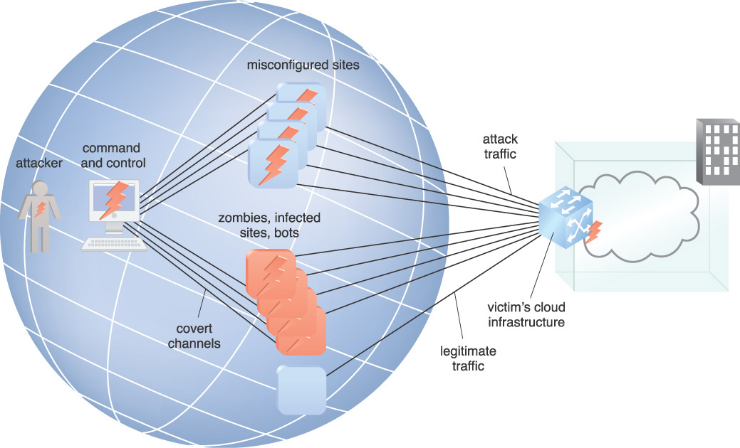
Botnets are made up of computers with malicious software installed, turning them into zombies that have conceded control to a command and control server. The controller of a botnet is able to direct the activities of these compromised computers to attack a victim, either directly or indirectly through the attack examples listed above, as well as others.
In Figure 9.11, the attacker has distributed a number of zombies, which are remotely controlled malware that can be directed at a victim as part of a DDoS attack. The attacker is also aware of a set of services that can be spoofed into responding to the victim’s imitated address. In this example, the attacker controls the botnet zombies that are compromised with malware, as well as other computers that inadvertently participate in attacks to launch DDoS attacks against the cloud provider’s infrastructure. These zombies communicate on a covert channel to connect with the command-and-control server that the attacker controls.
Solution
A DoS protection service is engaged, diverting all traffic that would otherwise directly hit the victim’s server infrastructure to the mitigation service network of datacenters, including attack traffic. Once traffic has shifted, the mitigation service absorbs the flood of attack traffic at the network edge, filters out the attack traffic, and prevents it from reaching the target’s infrastructure, allowing only the legitimate traffic through to the cloud provider.
Application
One approach strategy is to reroute traffic through the DDoS service provider when an attack is detected. Another more expensive option is to have the traffic flow through the service provider for fully automated detection and mitigation. This mitigation strategy is highly effective but can introduce additional latency and complexity to Internet connection and routing. The cloud provider engages a DoS attack mitigation service and updates DNS to route all traffic through the mitigation service. The cloud provider can also install a management network to accomplish the same function. Using an on-demand cloud DoS defense service for a network saturation attack coupled with an on-premise cloud resource defense that is always on provides protection against the whole spectrum of attacks.
Figure 9.12 illustrates the use of a DoS mitigation service. The service has the resources to monitor traffic with a traffic monitor to absorb the DoS attack and filter out and forward legitimate traffic to the cloud provider using a traffic filter. An implication is that DoS mitigation systems need to be tested periodically. Failure to regularly test those systems can lead to inadvertent amplification of an attack if the mitigation systems fail.
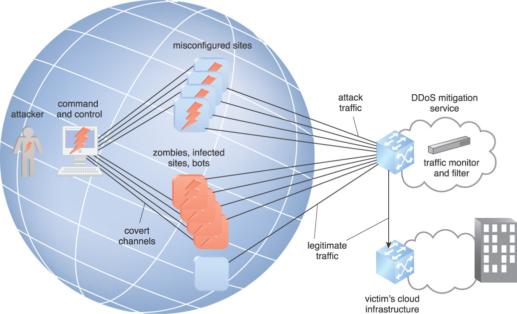
The solution is essentially a high capacity front end plus a mechanism that allows traffic with certain characteristics and origins to be ignored. An implication is that, in the hybrid scenario, the consumer’s outer network needs equipment to notify the DoS service when an attack is experienced, to take over the network traffic for filtering and forwarding of the good traffic. In all cases, the cloud service has their traffic initially routed to the DoS service protection provider.
Mechanisms
• Domain Name Service (DNS) – The DNS must be updated to route the cloud provider’s addresses through the DDoS mitigation service.
• Traffic Filter – The traffic filter is used to filter out malicious traffic.
• Traffic Monitor – The traffic monitor is used to detect DoS attack traffic.


Problem
The Border Gateway Protocol (BGP) can be used to launch traffic hijacking attacks by using fundamental flaws in the protocol itself. BGP, which calculates the quickest route for Internet traffic to travel in order for it to reach the destination IP address, can be subverted by undermining the trust relationship established by default between low-level Internet protocols.
IP hijacking, which can also be referred to as BGP prefix or route hijacking, is the seizing of groups of IP addresses by an attacker through the corruption of Internet routing tables. At the global level, individual IP addresses are grouped together into prefixes owned by an autonomous system. An example of autonomous systems is large Internet service providers.
The routing tables between autonomous systems are maintained using the BGP, which is the standard routing protocol used to exchange information about IP routing between autonomous systems. Attackers can infiltrate routers and take advantages of vulnerabilities in the BGP to route communications through their systems before routing it to the proper destination.
Communications traffic routes can be hijacked and routed to or through an attacker’s compute resource, as shown in Figure 9.13. They may be able to modify or passively monitor the data, or spoof the entire cloud service’s site.
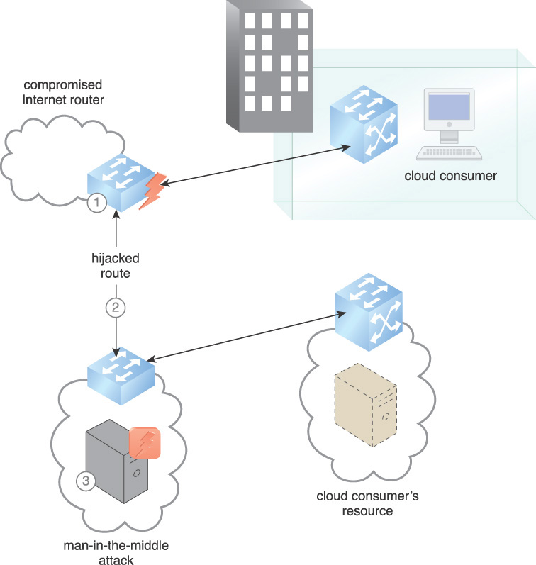
1. A compromised router enables a hijack to occur. Internet routers are capable of being secured, but there are inevitably routers that are not secured or susceptible to new vulnerabilities. Attackers can access vulnerable routers and execute man-in-the-middle (MITM) and/or hijack attacks.
2. The victim’s route after hijack. Normal routing of the network is disrupted and the packets are forwarded towards the attacker’s part of the network and are at the mercy of the offending autonomous system.
3. Cloud data can be copied or modified on the hijacker’s server as an MITM attack.
As a result of insecure communications protocols and routing equipment that can be compromised, there is a need to mitigate the constant risk.
Solution
Multiple precautions must be taken in order to protect from traffic hijacking, including traffic monitoring, data in-transit encryption, and integrity protection.
Application
Figure 9.14 depicts countermeasures that can be taken to prevent or mitigate traffic hijacking, as follows:
1. Where possible, encrypted communications channels are established either through VPNs or TLS sessions.
2. The data is signed and encrypted to protect confidentiality and integrity. As the data is being handled, it is assumed that there are malignant intermediaries on resources that are beyond the organization’s direct control. If a hijack occurs, the data is not compromised.
3. Strong authentication of resources is used. PKIs with keys that are stored in hardware security modules (HSMs) are used for resources to authenticate to the cloud consumer. Properly evaluated and configured crypto-modules mitigate spoofing of resources. A cryptographic key management system (CKMS) is implemented to manage encryption keys.
4. Network paths are monitored for suspicious behavior. Possible network hijack alerts are received and processed in realtime.
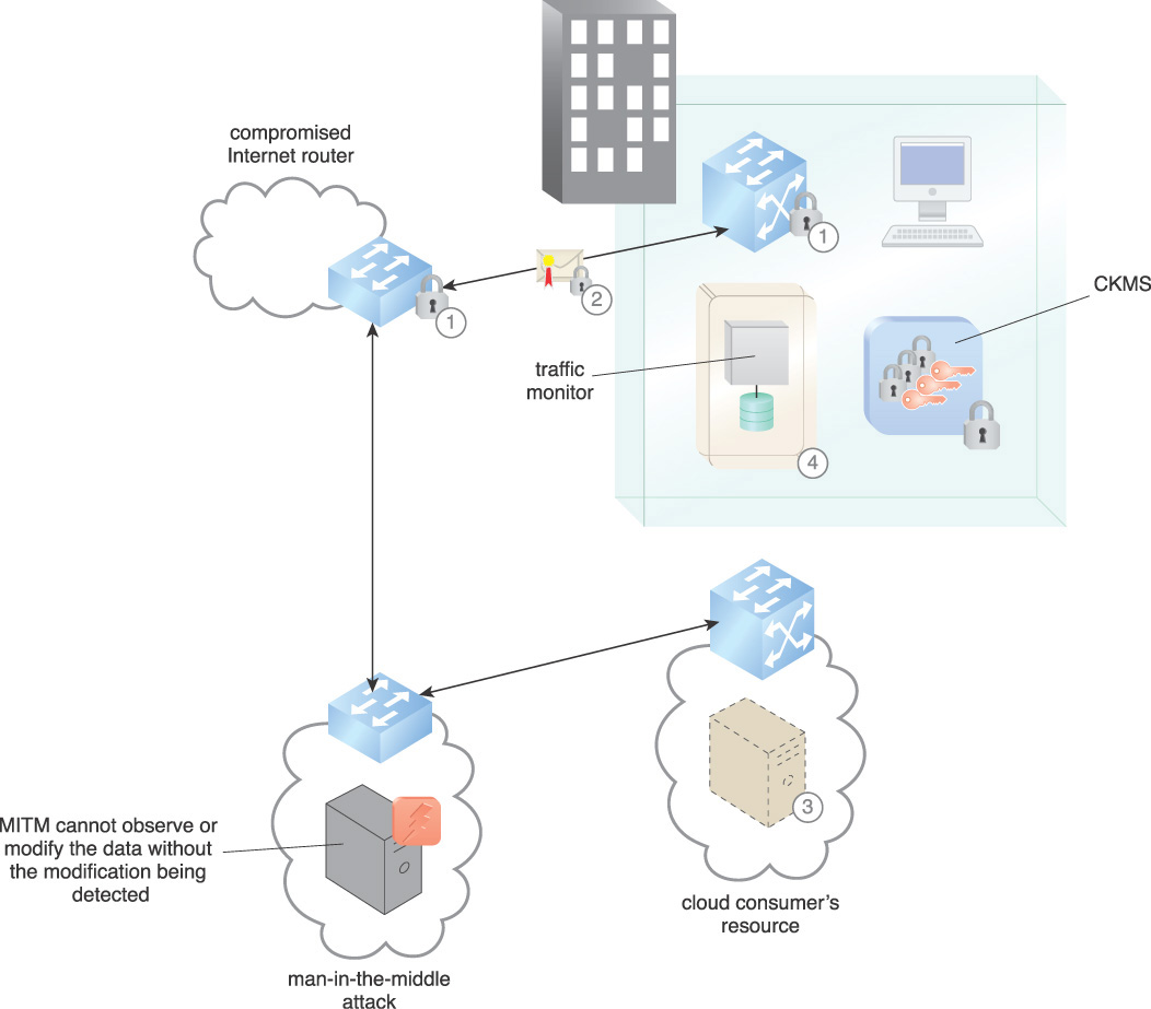
Until all routers in use by the organization are secured, including Internet routers, traffic hijacking can occur. Using signed and encrypted data, the MITM cannot observe or modify the data without the modification being detected. Although traffic hijacking can still occur, the application of this pattern ensures that data is not compromised and that the cloud consumer is alerted to the hijack.
Key management is critical to encryption and integrity security. Key management and traffic monitoring can be managed from a third party service or within the organization. The important aspect of traffic monitoring is determining what normal traffic flow is and providing alerts for anomalous traffic.
Implications include the need for personnel to be assigned with the responsibility to monitor and respond to possible traffic hijack alerts.
Mechanisms
• Cryptographic Key Management System (CKMS) – A CKMS manages the cryptographic keys used to encrypt the data prior to transmission and decrypt it at the destination.
• Digital Signature – A digital signature is used to ensure the integrity of the data in transit.
• Encryption – Encryption is used to ensure the confidentiality of the data in transit.
• Traffic Monitor – The traffic monitor is used by this pattern to detect traffic hijacking by noting normal traffic flow and alerting to anomalous traffic flow.
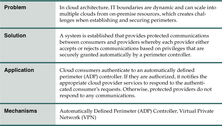
Automatically Defined Perimeter

How can a perimeter be protected that is dynamic and extends from on-premise to multi-vendor cloud resources?
Problem
Generally, an organization’s network architecture consists of an internal network that is protected from external networks, including the Internet, by a fixed defense of firewalls and routers. Cloud resource delivery and deployment models place boundaries in constant motion due to characteristics such as resource pooling and rapid elasticity. The advent of phishing attacks and addition of bring your own devices (BYODs) have the effect of placing untrusted access inside the perimeter. Many organizations have a requirement to connect on-premise resources with cloud resources. As an example, Figure 9.15 illustrates common attacks on vulnerabilities of resources on the extended network.
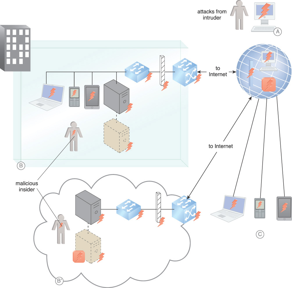
Figure 9.15 External attacks from intruders based worldwide (A). On-board attacks, from both on-premise and in the cloud (B). Vulnerabilities from mobile BYOD devices connected on-premise, in the cloud, or on the Internet (C).
Solution
A system is established that gives application owners the ability to create secure perimeters where and when they are required. Automatically defined perimeters (ADPs) are logical components that operate under the control of the cloud service or application owner. An ADP is based on a simple process of first identifying the device requesting access, then querying the identity system to determine what the cloud consumer is allowed to access, and then connecting the cloud consumer to the approved cloud applications with dynamically secured networking. ADPs provide access privileges to the protected infrastructure only after cloud consumer identification, authentication, and determination of access privileges. ADPs require endpoints to authenticate and be authorized before access is granted to protected resources. Connections are created between cloud consumers and cloud providers in realtime.
Application
The ADP controller regulates which services can communicate with each other. The controller may rely on authentication services, attribute services, geolocation services, policy services, and other security mechanisms to manage access.
The initiating services authenticate and communicate with the ADP controller to request a list of services to which they can connect. Protected services reject all communication from any resource except the ADP controller and any services that the ADP allows. The participating services accept connections only at the request of the ADP controller.
Figure 9.16 illustrates an ADP architecture containing ADP services and ADP controllers.
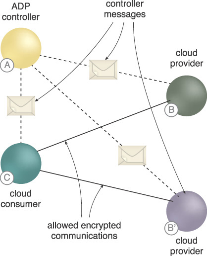
Figure 9.16 ADP cloud services can either be: access managed by requests to ADP controllers that rely on the organization’s identity and access management (IAM) (A), cloud providers that initially only respond to the ADP controller and then only to cloud consumers that have been authorized by the ADP controller (B), cloud consumers requesting a single service, multiple services, or a service orchestration (C).
In Figure 9.17, the organization must provision participating services to respond to requests, as shown in the following steps:
1. The initial cloud consumer authenticates to the ADP controller.
2. The ADP controller determines a list of cloud service providers to which the initial consumer is authorized to communicate.
3. The ADP controller securely instructs the requested cloud providers to accept communication from the initial cloud consumer as well as any required security policies such as the type of encrypted communications. It opens any network protections blocking the transaction.
4. The ADP controller securely gives the initial consumer the list of accepting providers as well as any security policies required for communications.
5. The initial consumer starts a secure connection to all authorized accepting providers.
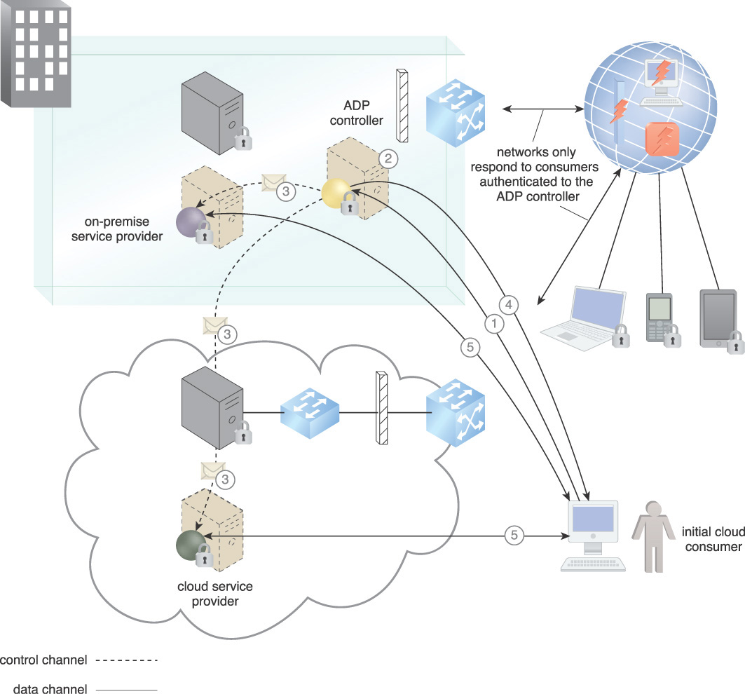
Figure 9.17 The participating cloud resources authenticate to the ADP and register with it when they are initially brought online.
The initial consumer starts a secure connection to all authorized accepting providers. For scaling and uptime requirements, the ADP infrastructure can be replicated and load balanced. The ADP brings together public key infrastructure (PKI), transport level security (TLS), Internet Protocol security (IPsec), security assertion markup language (SAML), and others. The ADP pattern is not intended to be applied to stand on its own. Other required protection, detection, and reaction-related patterns, such as Threat Intelligence Processing (465), should be applied as required, as well as concepts such as identity federation, attestation service, and geolocation to enable connectivity from any device to any infrastructure.
Connectivity in an ADP is based on a privilege model in which device identities are verified before access to application infrastructure is granted. Application infrastructure is effectively black, which is a US Department of Defense term that means the infrastructure cannot be detected.
Mechanisms
• Automatially Defined Perimeter (ADP) Controller – The ADP controller is used to manage secure connections between cloud consumers and cloud providers to maintain a secure perimeter.
• Virtual Private Network (VPN) – The VPN is used to create encrypted connections among the cloud consumers and cloud providers for an ADP session.
Cloud Authentication Gateway
How can cloud-based IT resources be made accessible to cloud service consumers with diverse protocol requirements?
Problem
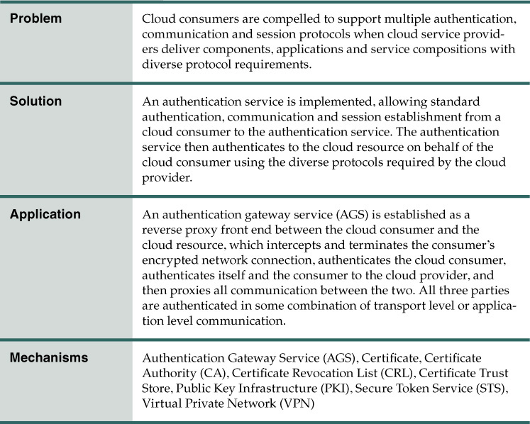
Applications, components and service compositions use multiple authentication mechanisms and protocols (Figure 9.18). This is especially true for legacy applications that have been moved into a cloud and can put multiple requirements on the cloud consumer for authentication, encrypted communication, and session establishment using tokens such as digital certificate, name/password, Kerberos, and Security Assertion Markup Language (SAML). Common communication protocols include HTTP, JSON-RPC, File Transfer Protocol (FTP), Simple Mail Transfer Protocol (SMTP), Secure Shell (SSH), and others.
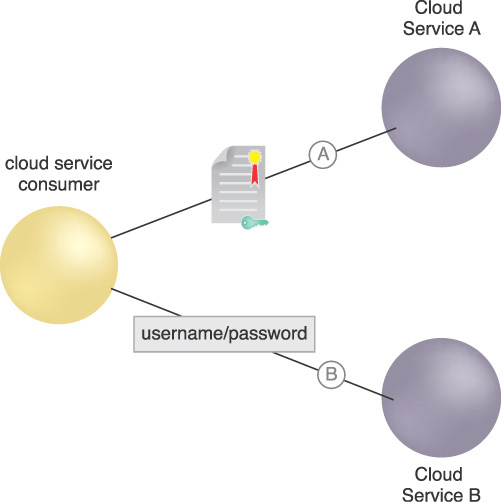
Figure 9.18 A cloud service consumer must support authenticating to Cloud Service A with a certificate over the HTTPS protocol and setting up a Kerberos session (A) and authenticating to Cloud Service Provider B with a username/password over the JSON-RPC protocol and setting up a session with a session object (B).
Solution
An AGS is established as a front end between the cloud consumer and the cloud service. The cloud consumer can be a person or a non-person entity (NPE), such as a component or Web service. The AGS intercepts and terminates the cloud consumer’s connection, authenticates the cloud consumer using a set of common standard protocols and tokens, and then acts on behalf of the cloud consumer in communication with the cloud service. In this arrangement, all traffic between the cloud consumer and the cloud service passes through the AGS.
Figure 9.19 illustrates the concept of an AGS. The cloud consumer can either use a certificate or a username/password, depending on the desired cloud service authentication requirements.
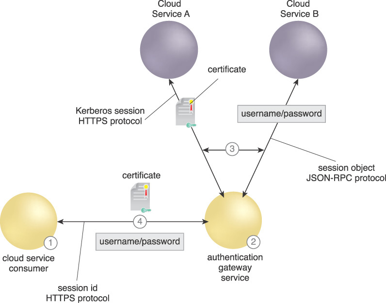
1. The cloud consumer requests a cloud business service using one standard protocol, HTTPS, and two types of identity tokens, certificate or username/password. It uses a session ID to maintain an established session.
2. The AGS authenticates the cloud consumer.
3. The AGS then authenticates itself and the cloud consumer to the requested cloud service provider using the authentication and session protocols particular to the specific service.
4. The AGS sets up a standard session between itself and the cloud consumer.
Without the AGS, the cloud consumer needs to process every protocol and token required by the cloud provider services involved at the authentication and session layer.
Application
A cloud-based AGS performs authentication to cloud services as a reverse proxy between the cloud consumer and cloud providers. This allows a single standard authentication API for the cloud consumers and accommodates the various authentication schemes required by the cloud providers. Figure 9.20 shows how the introduction of an AGS simplifies authentication and session establishment for the cloud consumer while increasing security. For certificate-based authentication, the AGS manages downloading of the CRLs for all relying party (RP) provided services, conducts certificate validation, and manages sessions between the cloud providers and cloud consumers. For cloud consumers with username/password tokens, the AGS provides a single secure location for managing and authenticating usernames and passwords.
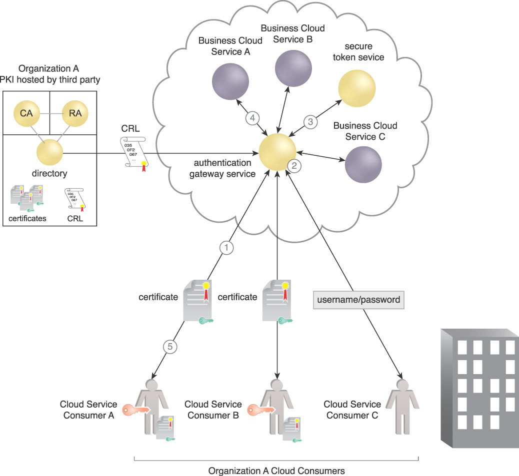
Figure 9.20 The AGS as a reverse proxy brokering among multiple authentication, communication and session protocols.
To ensure security, an AGS can be located within the security enclave of the cloud resources relying on the gateway as a reverse proxy. There are patterns whereby the AGS can reside within a cloud consumer’s enclave. The service can support REST- and SOAP-based Web service architecture protocols between the AGS and the cloud consumer. It can also support other component-based protocols between the AGS and the cloud services. The pattern is extensible and can handle any required combination of protocols on either side of the AGS. It acts as a broker and protocol translator for cloud services. The AGS provides a central point from which to monitor consumer access to resources.
The AGS has the capability to establish a one-way (as with username/password) or client-authenticated (as with mutual certificate authentication) TLS session, cloud consumer to AGS proxy, and AGS to cloud provider. It can also rely on Internet Key Exchange (IKE)-based VPNs for network security. However, all three parties are authenticated in some combination of transport level or application level communication.
The AGS performs as an authentication service as well as a proxy and application gateway. In Figure 9.20, the normal flow is as follows:
1. The cloud consumer attempts to access Cloud Service A. It is routed to the AGS as a proxy after a domain name service (DNS) lookup. Cloud Business Service Provider A requires the Kerberos protocol.
2. The AGS authenticates to the cloud consumer using its certificate, and the cloud consumer presents its credential. As part of authenticating the claimed identity presented in the cloud consumer’s credential, the AGS checks the credential’s authenticity and validity. Username/password credentials are validated locally against a directory or an account store (not shown). Certificates are validated by checking whether or not the credential is issued from a trusted source, whether or not it has expired, whether or not the certificate policy allows the current use, and also checks the revocation status of the credential from the CRL. The AGS certificate trust store holds the trusted issuing CA root certificates.
3. Once the cloud consumer is authenticated, the AGS provides a token request to the secure token service (STS) according to the cloud service’s requirements, and receives a token with the consumer’s attributes. With the Kerberos protocol, the STS performs key distribution center functions.
4. The AGS presents the authentication token to the requested cloud service. If the cloud service provider determines proper authorization and access privileges, it provides a Kerberos token and resource to the AGS.
5. The AGS provides a separate standard session token to the cloud consumer along with the resource. The cloud consumer continues an open session over the HTTPS/TLS with the cloud service provider as long as the session token and Kerberos are valid.
For other cloud providers with differing protocols, such as Business Service B and Business Service C in Figure 9.20, the concept of an authentication proxy using standard protocols with the cloud consumer and varied protocols with the cloud services is the same. Business Service B requires SAML tokens and Business Service C requires the JSON-RPC protocol. The AGS proxies the requests to the cloud consumers in a single standard way and mediates the varied protocols required by the cloud service providers.
An AGS may perform other functions, such as load balancing and logging. It provides a central location to log all authentication and resource accesses. It also provides a central place for CRL processing, alleviating multiple CRL downloads for every individual service.
An impact of using an AGS is that it becomes a single point of failure and a critical security infrastructure component that must be rigorously protected. AGSs need to be established in a high-availability load balanced configuration for continuity of operations (COOP) and be protected with firewall and routing access controls. All communication between cloud consumers and cloud provider services passes through the AGS, creating scaling and bandwidth issues. The AGS can ignore all traffic that is part of an authenticated session or monitor the session as an application gateway, which requires more processing power.
Mechanisms
• Authentication Gateway Service (AGS) – The AGS provides a reverse proxy to provide standard authentication to the cloud consumer and in turn authenticates to cloud services that have diverse protocols on behalf of the cloud consumer.
• Certificate – X.509 digital certificates are one form of standard cloud consumer identity claims used by the AGS.
• Certificate Authority (CA) – The CA issues the certificates used to fulfill the authentication requests for the application of this pattern.
• Certificate Revocation List (CRL) – The CRL is referenced to determine whether the certificates used in this pattern are revoked.
• Certificate Trust Store – The certificate trust store is referenced by the AGS to determine if the submitted certificate is issued from a trusted CA.
• Public Key Infrastructure (PKI) – A PKI establishes trust and issues certificates for an organization.
• Secure Token Service (STS) – The STS issues tokens to the AGS according to the standards and specifications required by the cloud services.
• Virtual Private Network (VPN) – The VPN is one method of creating a secure connection using X.509 certificates using the Internet Key Exchange (IKE) protocol.
Federated Cloud Authentication

How can X.509 certificates from a federation of cloud consumers be authenticated when an associated certificate revocation list fails?

Problem
A requirement of a federated enterprise is to share data among business partners across multiple organizations, meaning that the architecture must support authentication from individuals and services of diverse organizations. PKI certificates can be used throughout an enterprise to identify people as well as resources, including cloud services (REST and web services), transport layer security (TLS) and virtual private network (VPN) connection endpoints, as well as other components. These certificates must be validated when used for identification, authentication, and integrity checking. An interruption of the validation process by the denial of a current CRL for a given organization’s certificates can ripple throughout a cloud provider’s services that rely on certificates, resulting in an authentication denial-of-service.
The need to integrate composite cloud services across the enterprise and to share data among cloud consumers from diverse organizations securely and reliably derives from the requirement to provide authentication mechanisms adaptable to disconnected, intermittent, and limited (DIL) connectivity and varying performance and scaling requirements. When using X.509 certificates for cloud consumer identity claims, relying parties (RPs) normally download and check an issuing certificate authority (CA)’s CRL for the listing of the certificate. Figure 9.21 illustrates a certificate revocation process that compares a digital certificate’s serial number with those on the issuing authority’s CRL. The appearance of the serial number on the CRL indicates that the certificate has been revoked.
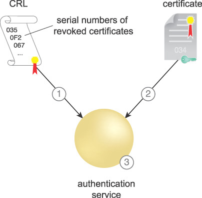
Certificate revocation processing occurs in the following steps, shown in Figure 9.21:
1. The CRL is downloaded from the PKI public repository and cached. When it expires, another current CRL is downloaded. If a current CRL is not available, certificate validation stops and RPs that require authentication normally stop authenticating.
2. A cloud consumer submits a certificate for access to a cloud resource. It is received by the authentication service.
3. The CRL is checked for a valid signature. It is checked to see if it is current. If not, the certificate cannot be validated, and processing normally stops at this point. If the CRL is valid, the certificate is checked to see if its serial is listed on it.
If a CRL is expired, the application normally rejects the authentication request from a cloud consumer, which can cause service disruption issues. Large and multiple CRLs can also cause source repository and network bandwidth performance issues, and consequently, continuity of operations (COOP) issues.
Solution
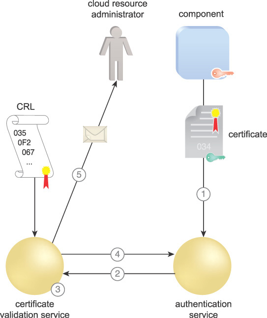
A local CVS is established, enabling the cloud consumer to authenticate to a resilient authentication service capable of validating certificates even using a stale CRL. An Online Certificate Status Protocol (OCSP) responder consumes CRLs and issues individual replies in response to revocation status requests about individual or groups of certificates. OCSP responders are capable of signing their own replies, and can continue to sign responses based on an expired CRL. This ensures continuity of operations if a failure in communications with the CRL repository or a failure of the PKI itself occurs. Figure 9.22 illustrates the process of a CVS using OCSP. When the cloud consumer needs services, in this case a component as a cloud service consumer:
1. It sends the required certificate to an authentication service to be authenticated.
2. The authentication service sends a request to the CVS that includes the issuer and serial number of the certificate.
3. The CVS compares the serial number with the associated issuer’s CRL to determine if the certificate is revoked.
4. The CVS signs a response indicating if the certificate is good, revoked, or unknown.
5. The CVS also checks to see that the CRL is valid. If the CRL is stale and the CVS cannot retrieve a current one, the CVS can be configured to send an alert to a cloud resource administrator notifying of a stale CRL. However, the CVS continues to sign revocation responses and the infrastructure continues to operate normally.
Application
A validation architecture is designed based on the validation security requirements of the cloud consumer. A CVS is implemented along with an authentication gateway service (AGS) to proxy authentication requests. A key component of the validation architecture is the establishment of trust. The security requirements establish the trust assurance level that the validation system needs to have.
CVSs are deployed to the local nodes to preserve operations during DIL conditions and to ensure performance reliability. They consume CRLs from the participating CAs when connectivity is available. When connectivity is not available, the local CVSs can respond based on stale CRLs and automatically notify administrators without disrupting the operation of any RPs. As a result, the cloud consumer is able to authenticate to a resilient authentication service that can validate certificates using a stale CRL.
In the case of multiple PKIs issuing millions of X.509 certificates, a local CVS allows large CRLs, sometimes on the order of hundreds of megabytes, to be managed by providing individual signed responses based on a downloaded CRL. Otherwise, the RP services must all download and manage the CRLs directly, increasing the required bandwidth of communications links and increasing the load on the directory servers holding the CRL.
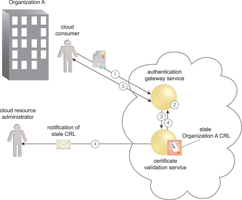
Figure 9.23 shows two separate organizations, one that issues its own certificates to cloud consumers and one that uses a third party. Both organizations share a common authentication service that accepts certificates from either organization. Their certificates are issued from their respective PKIs. Each PKI contains a CA to issue the certificates, a registration authority (RA) to approve issuance of the certificates, a public directory containing the issued certificates, and the CRL.
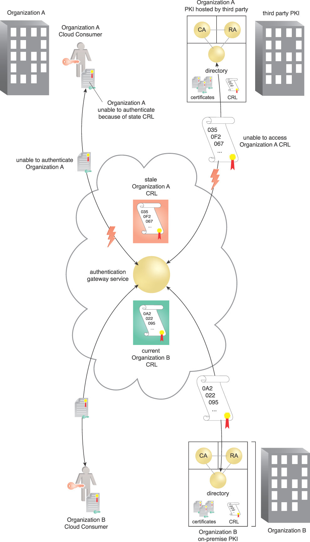
Figure 9.23 With the implementation of a CVS, the availability problems associated with an expired CRL are mitigated.
Organization A’s users are not able to authenticate to the federated authentication service because the CRL for their PKI is not available, and the one held by the cloud authentication service has expired. Organization B’s users continue to successfully authenticate to the federated authentication service as there is no availability interruption to their associated CRL.
The following steps are shown in Figure 9.24:
1. The cloud consumer wants to gain access to a cloud resource and attempts to connect to it via the AGS. The AGS requests authentication of the cloud consumer. It initiates a client/2-way certificate authenticated TLS session, enabling the cloud consumer to access their certificate, which is protected by a PIN. The cloud consumer enters their PIN to authenticate themselves to the private key and provides credentials to the cloud provider. The cloud consumer also authenticates the AGS’s certificate.
2. The AGS authenticates the cloud consumer’s certificate received during TLS session establishment. To authenticate the claimed identity presented in the cloud consumer’s credential, the AGS checks the authenticity and validity to determine whether the credential is issued from a trusted PKI, whether it is expired, and whether the certificate policy allows the current use. The AGS certificate trust store holds the trusted issuing CA root certificates.
3. The AGS sends a request for a revocation check to the CVS with the certificate serial number in question, as well as the issuer. However, the CRL corresponding to the CA that issued the certificate has expired and a fresh one is not available.
4. The CVS provides a revocation status (good, bad, or unknown) based on Organization A’s expired CRL and signs the response. This shows that the CVS is providing a signed validation based on an expired CRL. The CVS notifies the cloud resource administrator that the CRL is expired.
5. Assuming successful authentication and privileges, the AGS provides the resource.
Combined with all local security services, such as directory services for user accounts, the CVS ensures indefinite operation of all systems in the enclave in the event that they are cut off from the corresponding CRL of the enterprise security services. A Server-based Certificate Validation Protocol (SCVP) server in place of an OCSP server offloads all of the above validation processing from the AGS to the server.
There are several implications to implementing local CVS responders. The infrastructure requirements increase the size, complexity, and overall management costs of the IT environment. The signing CVSs have certificates and signing keys that need to be managed. Their security assurance level should be the same as the PKI for which they are authenticating.
Local infrastructure issues include:
• Selections of Mode of Validation – There are two modes of CVS operation: pre-signed validations and validations that are signed as they are issued. Pre-signed validation has performance advantages in providing a local CVS, but does not have any COOP advantages. The pre-signed OCSP responses are signed based on the current CRL and expire when the CRL expires. OCSP validations that are signed when they are issued can continue to be signed based on a stale CRL. Procedures and profiles must be developed to guide the RP on which mode to select based on requirements and how to configure the validator. SCVP is also an option to consider.
• Trust Model – There are multiple trust models for trusting the CVS. They must be analyzed and selected according to the security requirements.
• RP Connection to Service – Procedures and profiles must be developed to enable local relying parties to connect to the local CVS.
• DIL Procedures – Procedures and profiles need to be developed in case of wide area communications failure and inability to access a valid CRL. In such cases, the local administrators must be notified, and mission critical systems must continue to operate normally with an awareness of the risk and procedures activated to locally revoke certificates if required.
• Federation of Users – CVSs have the ability to trust more than one PKI and therefore allow users from diverse organizations to share data by validating all their certificates. The trust of participating organizations’ processes for vetting their individuals and services in order to issue credentials must also be addressed by determining security assurance levels of the PKIs involved. Procedures and profiles need to be in place to evaluate assurance policies of other PKIs for appropriateness for access to resources and configure CVSs to validate their certificates as required.
Mechanisms
• Certificate – X.509 digital certificates are the only form of cloud consumer identity claims used when applying this pattern.
• Certificate Authority (CA) – The CA issues the certificates and CRLs to be used to fulfill the authentication requests.
• Certificate Revocation List (CRL) – The CRL is referenced to determine whether the certificates are revoked.
• Certificate Trust Store – The certificate trust store holds issuing CA root certificates for multiple trusted organizations and is referenced by the AGS to determine if a submitted certificate is issued from a trusted CA.
• Certificate Validation Service (CVS) – The CVS is used by RPs to determine the validity of the submitted digital certificate and can continue to provide validation based on a stale CRL.
• Public Key Infrastructure (PKI) – The PKI issues certificates to each associated organization for use in authentication.

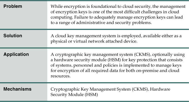
Problem
Encryption is used throughout the enterprise as the foundation for the security of data and platforms, including databases, identities, and network connections. The secure management of keys is critical as the compromise of keys can result in a compromise of the foundation of security systems.
Figure 9.25 shows the following common locations of keys that are used in the enterprise:
A. Asymmetric keys are used for identity, non-repudiation, and authentication. Asymmetric or symmetric keys can be used by an application to protect data.
B. TLS keys are asymmetric and are commonly used to securely exchange symmetric keys to protect data in motion.
C. VPN keys can be either symmetric or asymmetric, protecting data in motion. The VPN keys at the outer routers may be managed by the cloud provider or consumer.
D. Symmetric keys are used to provide VM security and data at rest.
E. VPN keys may be implemented on subnets and can also protect connections to the cloud.
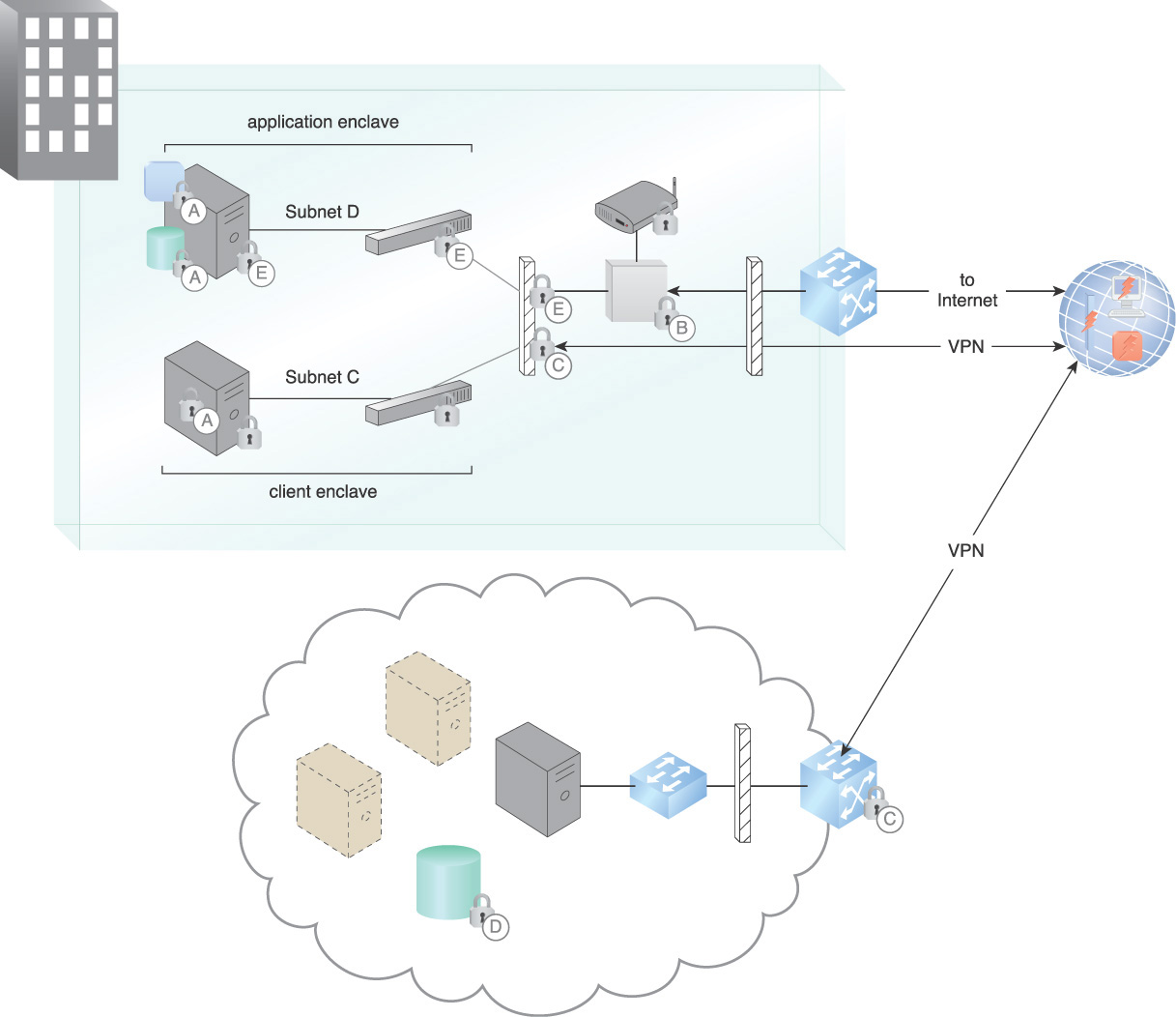
This example shows the requirement of a cloud consumer to manage a number of keys both for their on-premise resources and for their cloud resources.
Solution
A key management system is employed to manage the enterprise keys. It consists of administrators, policies, procedures, components, and devices used to protect, manage, and distribute cryptographic keys. A key management system includes all devices or sub-systems that can access an unencrypted key or its metadata. Encrypted keys and their cryptographically protected (bound) metadata can be handled by components and transmitted through communications systems and stored in media that are not considered to be part of a key management system.
Application
A cryptographic key management system (CKMS) is employed, supporting split key, separation of duties (SOD), and multi-person administration, and available either as a physical or virtual network attached device. The CKMS must encrypt the encryption keys and, depending on the requisite assurance level, provide for SOD, which requires multiple administrators to accomplish a particular administration task. Under SOD, split key technology is incorporated so that each administrator holds part of the split key and it takes as many administrators as required by the assurance level to supply all the parts of a key to unlock the CKMS. Depending on the throughput requirements, the key manager or a collection of key managers can be housed in a VM, automated and located near the workload that is being secured.
The major functions of the CKMS are illustrated in Figure 9.26. In this illustration, using a CKMS allows keys and encryption policy to be controlled by the cloud consumer data owner.
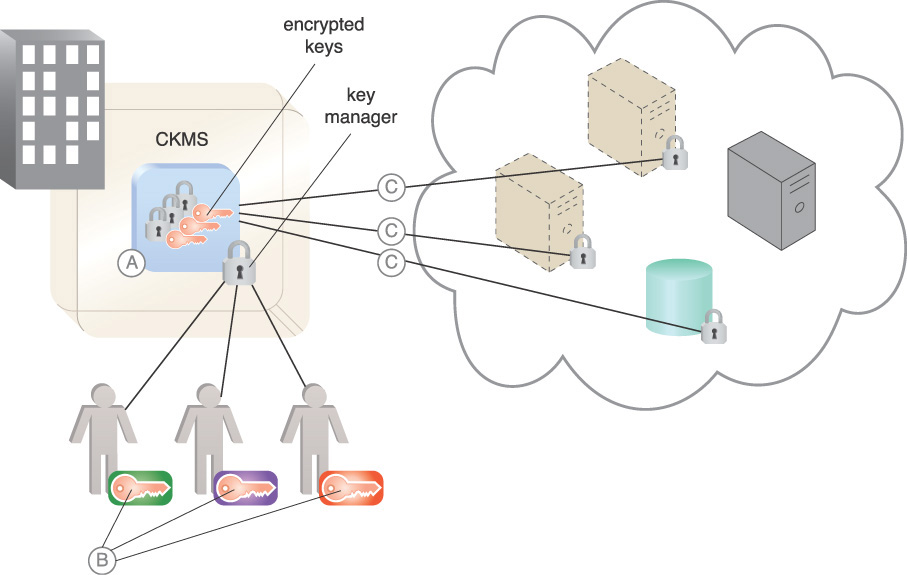
A. The CKMS houses and protects the cloud consumer’s keys in the key manager in encrypted form. For example, application keys are keys used by applications for their cryptographic operations and stored and protected within the HSM security boundary. Any operations requiring keys that are stored in the CKMS are performed by the CKMS on behalf of the end user, which prevents the end user from directly accessing the stored keys.
B. The lifecycle management (creation, renewal, management, destruction) of the keys is provided by CKMS administrators, who hold infrastructure keys that underpin the security of the CKMS. As an example, CKMS administrators hold control keys to unlock the CKMS for management purposes. Control keys are keys used to authorize the use of application keys in order to enforce security policies.
It normally takes more than one administrator to accomplish a CKMS function under the SOD principle. A split key system is used to support SOD so that multiple administrators are required in order to complete an administrative task, which is done by combining the keys that they separately control.
C. The keys corresponding to the encryption of various resources are stored in the CKMS and decrypted and activated by CKMS administrators with control keys. Public key infrastructure (PKI) issues asymmetric keys to identify consumers. Keys issued to non-person entities (NPEs), such as Web servers, are examples of keys managed by the CKMS. A log entry can be generated for each successful and unsuccessful use of key material in the CKMS, providing an audit trail for compliance and regulation purposes.
Depending on the required security assurance level, the CKMS can be housed in a hardware security module (HSM). An HSM is a dedicated cryptographic processor that is specifically hardened for the protection of the crypto key lifecycle. HSMs are trust anchors that protect the cryptographic infrastructure of organizations by supporting securely managing, processing, and storing cryptographic keys inside a hardened, tamper-resistant device. Implementing a CKMS operated by the cloud consumer organization is a trustworthy way to ensure the security of keys.
An impact is that there is a cost and complexity to operating a key management system. If a third party can meet the security assurance requirements for outsourcing key management, it can be an alternative to operating an on-premise key management regimen. Most compliance regulations reference NIST FIPS 140 standards and requirements for using evaluated cryptographic modules for CKMSs.
Mechanisms
• Cryptographic Key Management System (CKMS) – The CKMS provides a system to protect and manage organization keys and keep them safe from the attacker.
• Hardware Security Module (HSM) – The HSM is used to store keys in hardware for a higher level of security assurance.
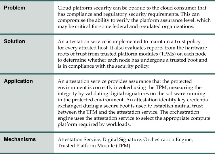
Trust Attestation Service
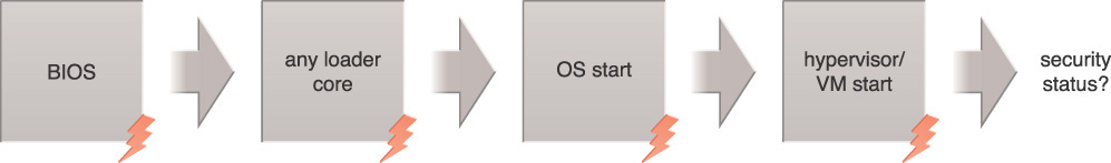
How can the security status of a cloud platform be communicated to cloud consumers?
Problem
To meet the security compliance requirements, the cloud consumer most often needs to know whether or not a compute resource is running a compliant BIOS, OS, hypervisor and VM at boot time. In a cloud environment, the entity requesting this information could be a resource scheduler or orchestrator trying to schedule a service on a set of available nodes or compute services. Figure 9.27 illustrates the need to securely record and report the security status of a compute resource.
Solution
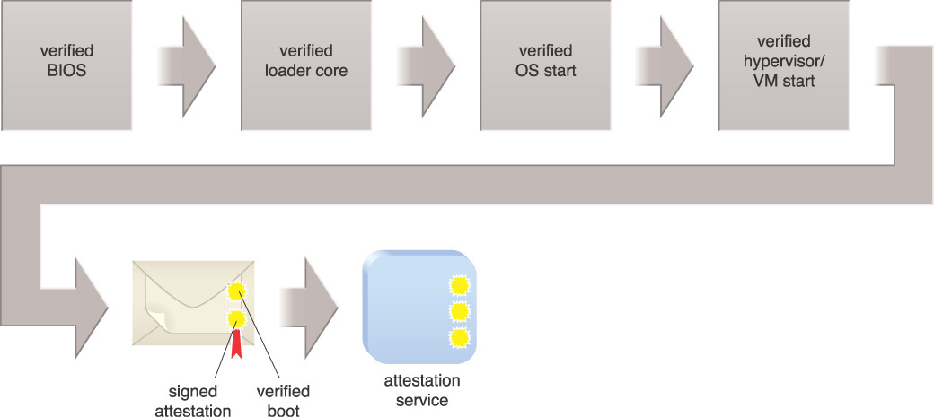
The attestation service accurately determines the state of the security relevant BIOS configuration items on each platform. This allows the attestation service to report on and act on the items with which the organization is concerned. Figure 9.28 illustrates the sequence of events in the secure boot reporting to the attestation service. Secure transmission of BIOS integrity measurements ensures that the measurements are not modified, disclosed, or forged in-transit by malicious parties.
Application
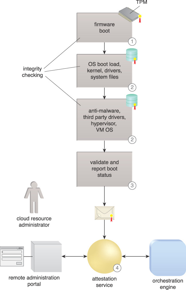
Measured boot can take measurements of different software components used in the OS boot process including the BIOS, OS loader, kernel, and drivers, and sign with a digital signature before securely storing the measurements in a trusted platform module (TPM). These measurements can be used by an attestation service to check the integrity of a given platform and to show that the platform has not been infected by malware. This attestation security service is a remote attestation service and can be provided by a trusted third party. It attests that the boot process of a particular machine is secure and that the anti-malware software on that machine is functioning properly. Figure 9.29 illustrates the use of an attestation service in the following steps:
1. A secure firmware boot prevents running an unknown OS loader by checking signatures called measured boot.
2. An early boot starts, first containing the OS, kernel, drivers, and other system files, and enforces security policy. It continues with a higher level of security booting of anti-malware, third party drivers, hypervisor, and VM operating system.
3. Digitally signed TPM boot measurements are recorded during the boot and sent securely to an off-box attestation service for analysis using attestation identity keys.
4. An attestation service provides the security status to the orchestration engine and authorized cloud administrators through an administration portal.
Attestation makes the status information from various roots of trust visible and usable by other entities. In the TPM-based implementation, it provides a digital signature of platform configurations in the TPM, extended with specific measurements for various launch modules of the software with the attestation service validating the digital signature of status messages. This is done so that subsequent agents cannot alter or replace the data without detection, and so the source of the data is known.
The implications of this pattern include the need to focus protection on the attestation service and to securely connect and authenticate to the attestation service, as it is central to reporting the security status of cloud resources.
Mechanisms
• Attestation Service – The attestation service provides levels of compute node security assurance to cloud consumers.
• Digital Signature – A digital signature is used to provide integrity of code.
• Orchestration Engine – The orchestration engine refers to the attestation service to ensure provisioned resources with the required security assurance level.
• Trusted Platform Module (TPM) – The TPM provides a tamper-resistant hardware security module (HSM) to hold keys and provide cryptographic processes.
Collaborative Monitoring and Logging
How can cloud monitoring and logging activities be coordinated between a cloud consumer and a cloud provider?
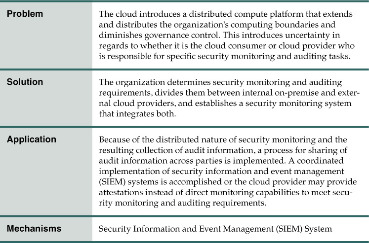
Problem
The organization has a responsibility to monitor for attacks and unauthorized local and remote connections. They are required to monitor for evidence of unauthorized disclosure of organizational information, and must detect any violation of computer security policies, industry compliance requirements, or standard security practices. One of the potential downsides of moving workloads to the cloud environment is loss of direct control. The enterprise security control requirements shift from the organization’s enterprise network alone to include the cloud. Administrators who previously had direct access to physical servers and console access to all logs and security monitoring output may now have limited accessibility.
However, according to best practices and many regulatory compliance requirements, organizations are accountable for the risk incurred by use of services provided by external providers and must address this risk by implementing compensating controls. Enterprises need to obtain sufficient assurance and security monitoring capabilities from external cloud providers to ensure that required security controls are in place. The issue is to work with the cloud provider to ensure that security monitoring tools meet compliance requirements, and that they are implemented to capture logs and machine data from operating systems, applications, and hardware devices.
The following requirements of cloud service types must be taken into account with security monitoring and logging:
• Private cloud – operated solely for one organization
• Community cloud – shared by several organizations
• Public cloud – available to any customer
• Hybrid cloud – two or more clouds (private, community, or public) that are connected
Depending on the service offering, for example IaaS, PaaS, or SaaS, only some of the necessary logs are directly available. Figure 9.30 illustrates the distributed nature of security monitoring in the cloud. The monitoring of identities accessing resources, security status of the resources, and security status of resource connectivity is vital to ensure secure transactions. Issues include the following facts:
A. Network traffic is spread out, including mobile devices accessing the network remotely.
B. Wireless network traffic extends the network.
C. The security status of resources that are distributed to the cloud, including their location, must be established, as well as on-premise resources.
D. Mobile devices, including tablets, phones, and laptops, must be monitored.
E. Man-in-the-middle attacks come from network devices on the Internet as well as agents placed inside data centers.
F. Malicious agents are constantly probing networks for vulnerabilities.
G. Malicious insiders have privileges within the enterprise but have malicious intent.
H. Authentication attempts originate from both internal and external consumers.

The various service model relationships between the cloud consumer and provider extend the organization’s network boundary and greatly increase the organization’s reliance on the cloud service provider’s security practices.
Solution
Functional and regulatory security and privacy requirements are determined to meet logging and security monitoring purposes. The auditing and security monitoring capabilities must meet any rules, laws, and regulations that bind the organization. Risk management supports identifying the set of requirements and control measures that must be used by the cloud consumer to monitor the cloud provider’s compliance with the services they offer. The information technology practices of the organization that pertain to the governance, policies, procedures, and standards used for logging and security monitoring of deployed or engaged services are extended to cloud computing environments.
Details about the system architecture of a cloud are analyzed and used to specify the protection required from the security and privacy controls, including mitigating risk by employing mechanisms and procedures for logging and for the continuous monitoring of the security state of the system. The mitigations that the organization normally uses to secure its data and infrastructure must extend to the cloud service provider. This requires the ability to accept the service provider’s attestation that its policies and procedures provide the required levels of protection.
Application
With regards to many types of industry compliance requisites, there are distinct requirements that security monitoring take place within the information system. This is achieved through security identification and event management (SIEM) for collecting and analyzing security events. Since cloud providers deliver features such as on-demand provisioning and multi-tenancy, the security monitoring solution must take into account the dynamic aspect of cloud computing boundaries. To ensure the continued effectiveness of the controls, the organization needs to manage the security monitoring environment and ensure that contractual obligations, rules, applicable laws, regulations, and policies that bind the organization are being met.
Audit data from various systems needs to be normalized for follow-on processing. The SIEM mechanism augmented by Big Data techniques can analyze security event data in realtime for internal and external threat management, and can collect, store, analyze, and report on log data for incident response, forensics, and regulatory compliance.
Organizations must create, protect, and store the audit records required to establish the monitoring, analysis, and reporting of inappropriate information system activity and ensure that the actions of individuals and components can be traced. The need to protect sensitive audit logs and the integrity of audit data is mandatory for effective security monitoring and is required by many compliance standards. The enterprise must implement a reference monitor that is tamperproof, always invoked, and that ensures that the security monitoring system is functioning properly. The tamperproof property of the reference monitor prevents attackers from compromising the function of the mechanism. The always invoked property prevents adversaries from bypassing the mechanism and compromising the security policy.
The following high-level steps to setting up a security monitoring program are shown in Figures 9.31 and 9.32:
1. Security requirements are developed, starting with industry regulatory requirements and other security measures considered necessary by the organization.
2. Security monitoring requirements from a regulatory compliance standpoint and other organizational monitoring requirements are derived from the security requirements.
3. Candidate SLA clauses for negotiation with prospective cloud providers are developed as a tool for evaluating the selected provider.
4. The cloud service provider delivers self-assessments of the ability to meet security monitoring requirements, either directly or indirectly, through third-party audit attestation.
5. After selecting a cloud provider, a third-party organization’s assessment is obtained that provides certifications of the candidate cloud service provider’s ability to meet the required level of security assurance.
6. A cloud provider’s security controls are implemented and integrated with the rest of the organization’s resources’ security controls, and their monitoring system is integrated with the organizational security monitoring system. Threat logic is developed that is suited to the shared environment and meets regulatory requirements for an effective alerting and reporting capability.
7. Continuous monitoring of the distributed enterprise commences, coordinating activities on-premise with the cloud provider. The cloud provider institutes continuous monitoring in accordance with the cloud consumer’s requirements and the SLA.
8. Periodic audits of the combined enterprise are conducted as required by the industry, incorporating audit attestations from the cloud provider.
9. The third-party assessment organization conducts periodic assessments of the cloud provider as required.
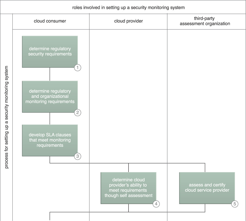
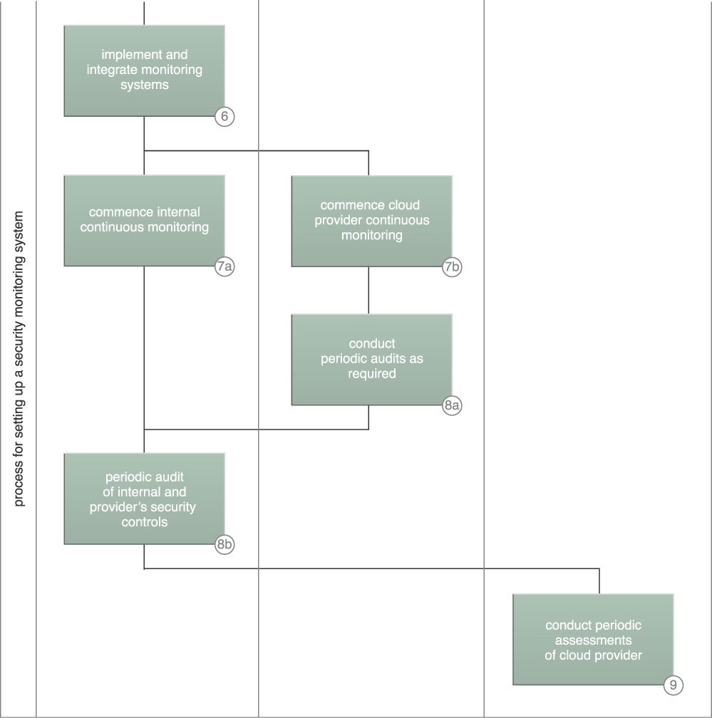
Organizations must accept the service provider’s attestation that its policies and procedures afford the organization the required levels of protection through independent audit reports or audits they conduct themselves. Ideally, security monitoring includes external monitoring of cloud assets and internal monitoring of on-premise resources. Security monitoring needs to be implemented through solution patterns and mechanisms (for example intrusion detection and prevention systems (IDPS), vulnerability scanning, endpoint protection mechanisms, device and application authentication, audit record monitoring, and network monitoring) and the output from security monitoring should serve as input to the SIEM implementation. In turn, the SIEM implementation serves as the backbone to information security continuous monitoring and incident response programs.
SIEM is critical to an effective security monitoring program. Advanced SIEM correlates event, threat, and risk data to accurately detect attacks in progress, serves as an investigation platform, and produces compliance reports resulting from security event monitoring. System monitoring relates to the health, performance, and processing consumption of an IT system. Application performance management (APM) is an overarching system monitoring application. Having a robust APM solution in which the SIEM can receive detailed audit information from workload transactions creates an important, mature, and insightful situational awareness capability.
Mechanisms
• Security Information and Event Management (SIEM) System – The SIEM collects audit data, performs realtime analysis of events against threat logic, and provides security alerting of monitored events.
Independent Cloud Auditing
How can cloud-hosted IT resources be audited for compliance and SLA requirements when they are not owned or accessible by cloud consumers?
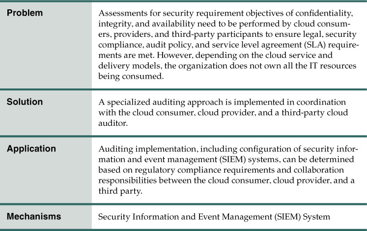
Problem
In order to meet industry compliance requirements, IT systems require implementation of strong auditing and compliance processes and procedures before a system can be approved for operation. The cloud consumer organization typically does not own or control all the underlying system resources that implement system capabilities when employing cloud resources.
Figure 9.33 provides an illustration of resource sharing between a typical cloud consumer and cloud provider. Policies, processes, and technical controls in support of regulations and auditing and legal requirements must be developed, requiring coordination between the cloud consumers and providers. All resources must be secured in a way that meets the required security levels and must be audited to prove compliance.
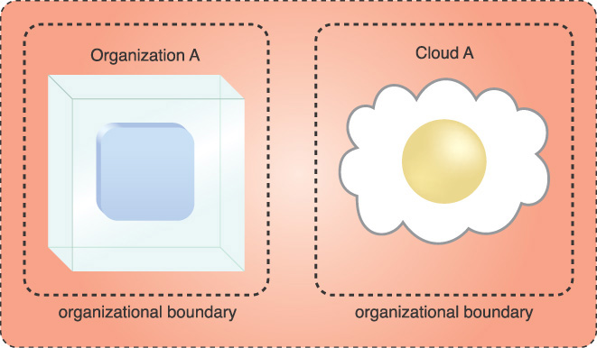
Solution
A third-party cloud auditor conducts an independent assessment of cloud services, information system operations, performance, and security of a cloud implementation.
Figures 9.34 and 9.35 illustrate the general process of setting up auditing:
1. The cloud consumer determines regulatory applicability for the use of a given cloud service.
2. In coordination with the cloud provider, the cloud consumer determines division of compliance responsibilities between the cloud provider and cloud consumer.
3. The cloud provider’s ability to produce evidence needed for compliance is determined.
4. The cloud consumer’s role in providing evidence from their on-premise resources and in bridging the gap between cloud provider and required audit information is determined.
5. Security controls for cloud consumers and cloud providers are implemented.
6. A trusted third party conducts certification and accreditation (C&A) of the enterprise with close cooperation of the cloud consumer and cloud provider. It is beneficial to include the auditor so that they can comment on the viability of audit data collection plans. Certification is an evaluation of processes, systems, and other associated artifacts based on an industry norm or standard, usually conducted by a third party. Accreditation is the formal determination that the certification program is administered in accordance with the relevant norms or standards of the certification program, usually also conducted by a third party.
7. The cloud provider sets up monitoring, logging, and reporting to meet audit requirements.
8. The cloud consumer sets up monitoring, logging, and reporting, incorporating the cloud provider’s reporting to meet audit requirements.
9. The cloud consumer and cloud provider conduct continuous monitoring for compliance requirements.
10. The cloud auditor collects evidence from the cloud consumer and cloud provider that is used to conduct an audit.
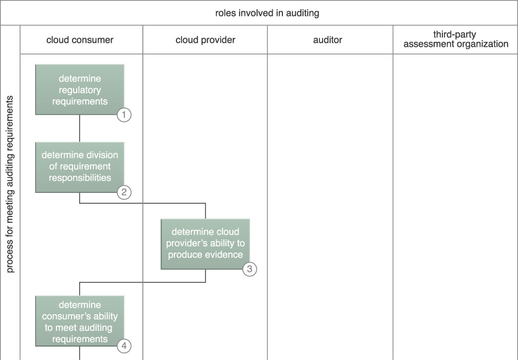
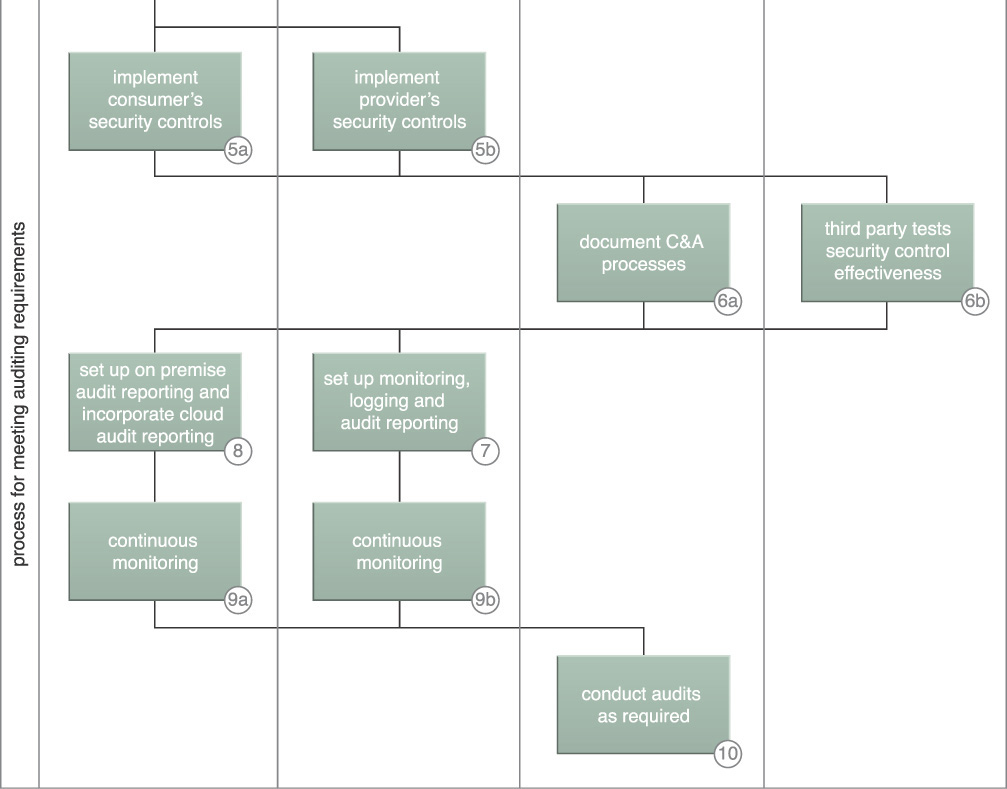
Application
Cloud service consumers and cloud service providers make their performance and security data available for auditors in accordance with relevant compliance frameworks such as the Payment Card Industry Data Security Standard (PCI DSS), the Health Insurance Portability and Accountability Act (HIPAA), Control Objectives for Information and Related Technology (COBIT), International Organization for Standardization (ISO) and International Electrotechnical Commission (ISO/IEC) 27002, the Sarbanes-Oxley Act (SOX), NIST Special Publication 800-53, Security and Privacy Controls for Federal Information Systems and Organizations, or another industry-oriented standard.
The cloud auditor makes an assessment of the security controls of the information system in order to determine the extent to which the controls are implemented correctly, operating as intended, and producing the desired outcome with respect to the security requirements for the system. The security auditing requires the verification of the compliance with regulation and security policy of the security controls for management, operational, and technical mechanisms implemented within the organizational information system boundary to protect the confidentiality, integrity, and availability of the system and its information.
A security information and event management (SIEM) system should be implemented to coordinate logging of event sources including operating systems, applications, databases, network and security components.
Among other implications, organizations must create, protect, and retain information system audit records to the extent needed to enable the monitoring, analysis, investigation, and reporting of unlawful, unauthorized, or inappropriate information system activity. They must also ensure that the actions of individual information system users can be uniquely traced to those users so they can be held accountable for their actions.
Mechanisms
• Security Information and Event Management (SIEM) System – A SIEM system is used to conduct continuous monitoring as required and coordinate the collection of information for auditing.
Threat Intelligence Processing

How can actionable threat indicators be generated to detect threats and prevent cloud vulnerability exploits?
Problem
With its high volume of threat data and sophistication of threats, the threat landscape poses severe security challenges for an organization seeking to prevent exploits of their vulnerabilities. For example, there are domain names, applications, and countries of origin that should be blacklisted to reduce particular types of threats. Events such as specific application attacks, ports and services that are vulnerable, and the current malware being detected need to be collected and analyzed as part of security planning. The issue lies in finding a way to collect, analyze, and integrate threat intelligence knowledge operationally into cloud security systems for exploit prevention.
Figure 9.36 shows the following internal and external sources of information for threat intelligence:
A. External intelligence sources include:
• Raw intelligence from threat data such as malicious IP addresses, domain name system (DNS) names, URLs, malware hashes, etc.
• Threat information sharing from organizations, companies, and crowd sourcing.
• Computer Emergency Readiness Team (CERT) alerts.
B. Internal intelligence sources include:
• Raw intelligence from malicious activity detected inside the organizational boundaries.
• Information gathered from operating unknown executables in a sandbox.
• Observations of malicious activity in honeypots.
• Analysis of data observed that is internal to the organization.
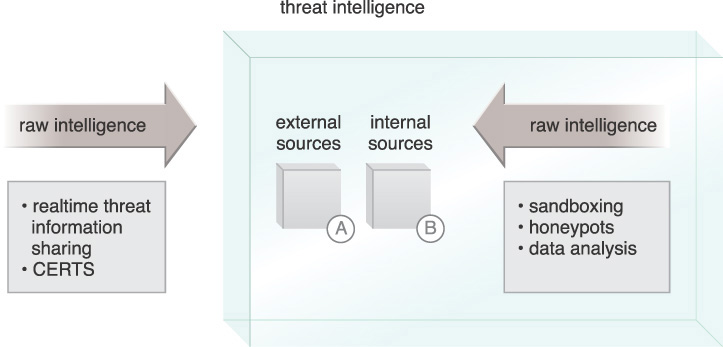
As a result of this large volume of threat data, there is a need to analyze and create queuing for the organization’s protection mechanisms. For example, if a participant of an information sharing organization experiences a zero-day attack and makes the characteristics of the attack available to the information sharing participants, they can take measures to protect from the attack.
Solution
Threat intelligence provides indications and warnings about threats that are likely to occur. Threat intelligence can provide attacker tactics, techniques, and procedures that organizations have experienced and mitigations that organizations have found that are effective against certain types of threats. Threat intelligence includes collecting and analyzing threat actors, exploits, malware, vulnerabilities, and compromise indicators. It is fed by collaborative realtime threat intelligence received from the community, as well as internal analysis. Exploit prevention derives from an understanding of threats and threat behavior.
Figure 9.37 shows collection, analysis, distribution, and use of analysis information. The data is automatically distributed to attack mitigation components in the enterprise, providing automatic update of security configurations. The automatic updates extend to cloud consumers’ browser protection systems.
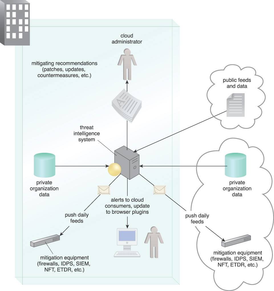
Application
A threat intelligence system is implemented, which alerts the organization to threat agents, their intended targets, attack campaigns, and known tactics, techniques, and procedures (TTPs). Using a threat intelligence system, the organization can institute threat prevention controls for actionable intelligence in the form of indicators and attack descriptions. Those indicators allow organizations to anticipate attacks before they unfold, and also to recognize their significance when detected in the network. An automatic update to protection mechanisms is configured for a realtime protection component of the threat intelligence system.
Actionable intelligence from threat intelligence can inform cloud consumers and providers, and includes:
• Observed malicious behavior and attributes, such as malicious network addresses, domain name resolution requests, URLs, system calls, and file hashes.
• Where attacks are observed, for example on the network, inside emails or documents, on the disk, in memory, etc.
• Criticality/priority of the event or series of events. Metadata provides additional information on the confidence level for the indicator, the severity of the corresponding attack, etc.
• How to protect against a particular attack by considering such factors as whether the attack should be blocked on the network or on the host, or whether or not a patch should be applied for vulnerability.
• Automatic updates to protection device configurations where possible.
Organizations should expect to receive a steady stream of threat intelligence without requiring manual intervention. Information Sharing and Analysis Organizations (ISAOs) share cybersecurity information between the private industry and the government. Threat intelligence sources include public security intelligence, such as CERTs and Computer Security Incident Response Teams (CSIRTs), as well as various security analysts, security product vendors and other organizations within the security community. Threat intelligence is generated within the enterprise through honeypots, sandboxing techniques, and data analysis of security events collected from enforcement points.
Implications include the fact that threat information may be highly sensitive, requiring special agreements and protection. Personnel must be given the responsibility to manage sharing agreements and coordination for usage of the queueing data.
Mechanisms
• Endpoint Threat Detection and Response (ETDR) – The threat intelligence system uses the data collected from the ETDR and queues the ETDR with emerging threat profiles.
• Honeypot – The honeypot captures and observes malicious behavior and provides the information to the threat intelligence system.
• Intrusion Detection and Prevention System (IDPS) – The threat intelligence system uses the data collected from the IDPS and queues the IDPS with emerging threat profiles.
• Malware Hash – Malware hashes are collected by the threat intelligence system and distributed to anti-malware systems for reference.
• Network Forensics Monitor – The network forensics monitor is used to search for threats as queued from the threat intelligence system.
• Sandbox – When the sandbox finds a malicious executable, it provides the attributes to the threat intelligence system.
• Security Information and Event Management (SIEM) System – The SIEM is used to search for breaches as queued by the threat intelligence system.
• Threat Intelligence System – The threat intelligence system is used to analyze threat intelligence and queue defense mechanisms.