CHAPTER 14
Wireless Networking
The CompTIA Network+ certification exam expects you to know how to
• 1.3 Explain the concepts and characteristics of routing and switching
• 1.5 Compare and contrast the characteristics of network topologies, types and technologies
• 1.6 Given a scenario, implement the appropriate wireless technologies and configurations
• 2.2 Given a scenario, determine the appropriate placement of networking devices on a network and install/configure them
• 2.3 Explain the purposes and use cases for advanced networking devices
• 4.2 Explain authentication and access controls
• 4.3 Given a scenario, secure a basic wireless network
• 4.4 Summarize common networking attacks
• 5.2 Given a scenario, use the appropriate tool
• 5.4 Given a scenario, troubleshoot common wireless connectivity and performance issues
• 5.5 Given a scenario, troubleshoot common network service issues
To achieve these goals, you must be able to
• Explain wireless networking standards
• Describe the process for implementing Wi-Fi networks
• Describe troubleshooting techniques for wireless networks
Every type of network covered thus far in the book assumes that your PCs connect to your network with some kind of physical cabling. Now it’s time to cut the cord and look at the many technologies that collectively changed the way we use the Internet: wireless networking.
Historical/Conceptual
You need to be careful when talking about wireless networking. Wireless is everywhere. It’s in our phones and our homes. It’s at work and in our schools. Wireless is so transparent and handy we tend to forget that wireless isn’t a single technology. There are a number of technologies that collectively make up wireless networking.
Let’s start with the basics. Instead of a physical set of wires running among networked PCs, servers, printers, or what-have-you, a wireless network uses radio frequency (RF) waves to enable these devices to communicate with each other. Wireless technologies disconnected us from the wires that started the networking revolution and have given us incredible flexibility and mobility.

NOTE Because the networking signal is freed from wires, you’ll sometimes hear the term unbounded media to describe wireless networking.
For all their disconnected goodness, wireless networks share more similarities than differences with wired networks. With the exception of the first two OSI layers, wireless networks use the same protocols as wired networks. The thing that differs is the type of media—radio waves instead of cables—and the protocols for transmitting and accessing data. Different wireless networking solutions have come and gone in the past, but the wireless networking market these days is dominated by the most common implementation of the IEEE 802.11 wireless standard, Wi-Fi.
This chapter looks first at the standards for modern wireless networks and then turns to implementing those networks. The chapter finishes with a discussion on troubleshooting Wi-Fi.
Test Specific
Wi-Fi Standards
Wi-Fi is by far the most widely adopted wireless networking type today, especially for accessing the Internet. You’d be hard pressed to find a location, work or home, that doesn’t have Wi-Fi. Millions of private businesses and homes have wireless networks, and most public places, such as coffee shops and libraries, offer Internet access through wireless networks.
NOTE Wi-Fi originally stood for wireless fidelity to make it cutely equated with high fidelity (Hi-Fi), but it doesn’t really stand for anything anymore.
Wi-Fi technologies have been around since the late 1990s, supported and standardized under the umbrella IEEE 802.11 standard. So in reality, Wi-Fi is really 802.11. The 802.11 standard has been updated continuously since then, manifested by a large number of amendments to the standard. These amendments have names such as 802.11g and 802.11ac. It’s important for you to understand all of these 802.11 amendments in detail, as well as the original version, 802.11.
802.11
The 802.11 standard defines both how wireless devices communicate and how to secure that communication. The original 802.11 standard, now often referred to as 802.11-1997, is no longer used, but it established the baseline features common to all subsequent Wi-Fi standards.
The 802.11-1997 standard defined certain features, such as a wireless network cards, special configuration software, and the capability to run in multiple styles of networks. In addition, 802.11-1997 defined how transmissions work, so we’ll look at frequencies of radio signals, transmission methods, and collision avoidance.
Hardware
Wireless networking hardware serves the same function as hardware used on wired PCs. Wireless Ethernet NICs take data passed down from the upper OSI layers, encapsulate it into frames, send the frames out on the network media in streams of ones and zeroes, and receive frames sent from other computing devices. The only difference is that instead of charging up a network cable with electrical current or firing off pulses of light, these devices transmit and receive radio waves.
NOTE It’s the same concept, but 802.11 frames are not addressed and encapsulated the same way as 802.3 Ethernet frames.
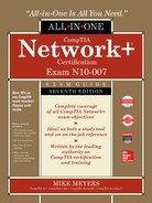
Wireless networking capabilities of one form or another are built into many modern computing devices. Almost all portable devices have built-in wireless capabilities. Desktop computers can easily go wireless by adding an expansion card. Figure 14-1 shows a wireless PCI Express (PCIe) Ethernet card.
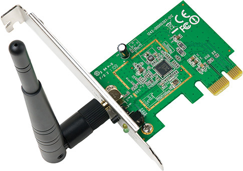
Figure 14-1 Wireless PCIe NIC
You can also add wireless network capabilities using USB wireless network adapters, as shown in Figure 14-2. The USB NICs have the added benefit of being placeable—that is, you can move them around to catch the wireless signal as strongly as possible, akin to moving the rabbit ears on old pre-cable television sets.
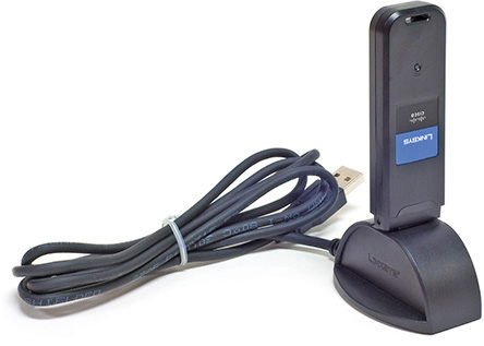
Figure 14-2 External USB wireless NIC
Is the wireless network adapter in all your devices the only hardware you need to create a wireless network? Well, if your needs are simple—for example, if you’re connecting a few laptops on a long train ride so you and your buddies can play a game together—then the answer is yes. If, however, you need to extend the capabilities of a wireless network—say, connecting a wireless network segment to a wired network—you need additional equipment. This typically means a wireless access point.
A wireless access point (WAP) is a device designed to interconnect wireless network nodes with wired networks. A basic WAP operates like a hub and works at OSI Layer 1. Many WAP manufacturers combine multiple devices into one box, however, to create a WAP with a built-in switch and/or router, all rolled into one and working at several OSI layers. The Linksys device shown in Figure 14-3 is an example of this type of combo device.
Figure 14-3 Linksys device that acts as wireless access point, switch, and DSL router
NOTE Many manufacturers drop the word “wireless” from wireless access points and simply call them access points. Furthermore, many sources abbreviate both forms, so you’ll see the former written as WAP and the latter as AP.
Software
Every wireless network adapter needs two pieces of software to function with an operating system: a device driver to talk to the wireless NIC and a configuration utility. Installing drivers for wireless networking devices is usually automatic these days, but you should always consult your vendor’s instructions before popping that card into a slot.
You also need a utility for configuring how the wireless hardware connects to other wireless devices. Every operating system has built-in wireless clients for configuring these settings, but these clients may lack advanced features for more complex wireless networks, requiring wireless clients provided by the wireless network adapter vendor or a third party. Figure 14-4 shows a typical wireless network adapter’s client configuration utility. Using this utility, you can determine important things like the link state (whether your wireless device is connected) and the signal strength (a measurement of how well your wireless device is connecting to other devices). You can also configure items such as your wireless networking mode, security encryption, power-saving options, and so on. I’ll cover each of these topics in detail later in this chapter.
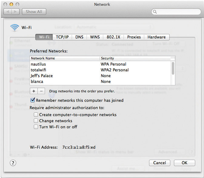
Figure 14-4 Wireless client configuration utility
You typically configure WAPs through browser-based setup utilities. The section “Implementing Wi-Fi” covers this process a bit later in this chapter. For now, let’s look at the different modes that wireless networks use.
Wireless Network Modes
802.11 networks operate in one of two modes. In the uncommon ad hoc mode, two or more devices communicate directly without any other intermediary hardware. The much more common infrastructure mode uses a WAP that, in essence, acts as a hub for all wireless clients. A WAP also bridges wireless network segments to wired network segments.
Ad Hoc Mode Ad hoc mode is sometimes called peer-to-peer mode, with each wireless node in direct contact with each other node in a decentralized free-for-all, as shown in Figure 14-5. Ad hoc mode does not use a WAP and instead uses a mesh topology, as discussed in Chapter 2, “Cabling and Topology.”
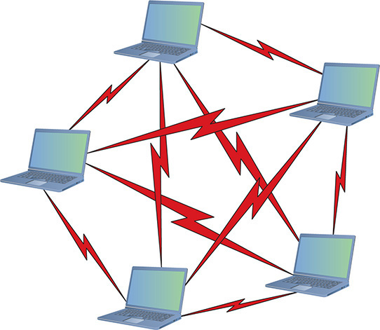
Figure 14-5 Wireless ad hoc mode network
Two or more wireless nodes communicating in ad hoc mode form an Independent Basic Service Set (IBSS). This is a basic unit of organization in wireless networks. If you think of an IBSS as a wireless workgroup, you won’t be far off the mark.
Ad hoc mode networks work well for small groups of computers (fewer than a dozen or so) that need to transfer files or share printers. Ad hoc networks are also good for temporary networks, such as study groups or business meetings.
Hardly anyone uses ad hoc networks for day-to-day work, however, simply because you can’t use an ad hoc network to connect to other networks (unless one of the machines is running Internet Connection Sharing [ICS] or some equivalent).
Infrastructure Mode Wireless networks running in infrastructure mode use one or more WAPs to connect the wireless network nodes centrally, as shown in Figure 14-6. This configuration is similar to the physical star topology of a wired network. This creates a wireless local area network (WLAN). You also use infrastructure mode to connect wireless network segments to wired segments. If you plan to set up a wireless network for a large number of computing devices, or you need to have centralized control over the wireless network, use infrastructure mode.
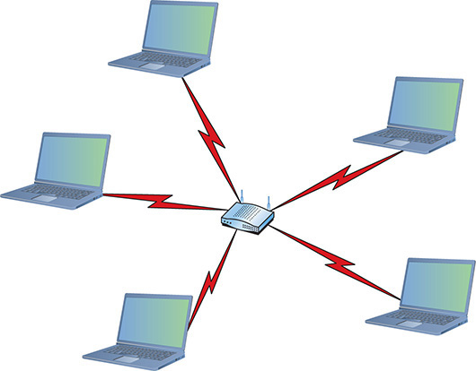
Figure 14-6 Wireless infrastructure mode network
A single WAP servicing a given area is called a Basic Service Set (BSS). This service area can be extended by adding more access points. This is called, appropriately, an Extended Service Set (ESS).
NOTE Many techs have dropped the word “basic” from the Extended Basic Service Set, the early name for an infrastructure-mode wireless network with more than one WAP. Accordingly, you’ll see the initials for the Extended Basic Service Set as ESS. Using either EBSS or ESS is correct.
Wireless networks running in infrastructure mode require a little more planning—such as where you place the WAPs to provide adequate coverage—than ad hoc mode networks, and they provide a stable environment for permanent wireless network installations. Infrastructure mode is better suited to business networks or networks that need to share dedicated resources such as Internet connections and centralized databases. (See “Implementing Wi-Fi” later in this chapter.)
Range
Wireless networking range is hard to define. You’ll see most descriptions listed with qualifiers such as “around 150 feet” and “about 300 feet.” Wireless range is greatly affected by environmental factors. Interference from other wireless devices and solid objects affects range.
The maximum ranges listed in the sections that follow are those presented by wireless manufacturers as the theoretical maximum ranges. In the real world, you’ll achieve these ranges only under the most ideal circumstances. Cutting the manufacturer’s listed range in half is often a better estimate of the true effective range.
BSSID, SSID, and ESSID
Wireless devices connected together into a network, whether ad hoc or infrastructure, require some way to identify that network. Frames bound for computers within the network need to go where they’re supposed to go, even when you have overlapping Wi-Fi networks. The jargon gets a little crazy here, especially because marketing has come into the mix. Stay with me.
The Basic Service Set Identifier (BSSID) defines the most basic infrastructure mode network—a BSS of one WAP and one or more wireless clients. With such a simple network, the Wi-Fi folks didn’t see any reason to create some new numbering or naming scheme, so they made the BSSID the same as the MAC address for the WAP. Simple! Ah, but what do you do about ad hoc networks that don’t have a WAP? The nodes that connect in an IBSS randomly generate a 48-bit string of numbers that looks and functions just like a MAC address, and that BSSID goes in every frame.
You could, if required, discover the MAC address for the WAP in a BSS and manually type that into the network name field when setting up a wireless computer. But that causes two problems. First, people don’t want to remember strings of 48 binary digits, even if translated out as six hexadecimal octets, like A9–45–F2–3E–CA–12. People want names. Second, how do you connect two or more computers together into an IBSS when the BSSID has to be randomly generated?
The Wi-Fi folks created another level of naming called a Service Set Identifier (SSID), a standard name applied to the BSS or IBSS to help the connection happen. The SSID—sometimes called a network name—is a 32-bit identification string that’s inserted into the header of each frame processed by a WAP. Every Wi-Fi device must share the same SSID to communicate in a single network. By default, a WAP advertises its existence by sending out a continuous SSID broadcast. It’s the SSID broadcast that lets you see the wireless networks that are available on your wireless devices.
To really see the power of 802.11 in action, let’s take it one step further into a Wi-Fi network that has multiple WAPs: an ESS. How do you determine the network name at this level? You just use the SSID, only you apply it to the ESS as an Extended Service Set Identifier (ESSID). In an ESS, every WAP connects to a central switch or switches to become part of a single broadcast domain.
With multiple WAPs in an ESS, clients will connect to whichever WAP has the strongest signal. As clients move through the space covered by the broadcast area, they will change WAP connections seamlessly, a process called roaming.
Most Wi-Fi manufacturers just use the term SSID, by the way, and not ESSID. When you configure a wireless device to connect to an ESS, you’re technically using the ESSID rather than just the SSID, but the manufacturer often tries to make it simple for you by using only the term SSID.
Broadcasting Frequency
One of the biggest issues with wireless communication is the potential for interference from other wireless devices. To solve this, different wireless devices must operate in specific broadcasting frequencies. Knowing these wireless frequency ranges will assist you in troubleshooting interference issues from other devices operating in the same wireless band. The original 802.11 standards use either 2.4-GHz or 5.0-GHz radio frequencies.
Broadcasting Methods
The original IEEE 802.11 wireless Ethernet standard defined methods by which devices may communicate using spread-spectrum radio waves. Spread-spectrum broadcasts data in small, discrete chunks over the different frequencies available within a certain frequency range.
The 802.11 standard defines three different spread-spectrum broadcasting methods: direct-sequence spread-spectrum (DSSS), frequency-hopping spread-spectrum (FHSS), and orthogonal frequency-division multiplexing (OFDM). DSSS sends data out on different frequencies at the same time, whereas FHSS sends data on one frequency at a time, constantly shifting (or hopping) frequencies. DSSS uses considerably more bandwidth than FHSS—around 22 MHz as opposed to 1 MHz. DSSS is capable of greater data throughput, but it’s also more prone to interference than FHSS. OFDM is the latest of these three methods, better at dealing with interference, and is used on all but the earliest 802.11 networks.
Channels
Every Wi-Fi network communicates on a channel, a portion of the spectrum available. For the 2.4-GHz band, the 802.11 standard defines 14 channels of 20-MHz each (that’s the channel bandwidth), but different countries limit exactly which channels may be used. In the United States, for example, a WAP using the 2.4-GHz band may only use channels 1 through 11. These channels have some overlap, so two nearby WAPs should not use close channels like 6 and 7. WAPs use channels 1, 6, or 11 by default because these are the only non-overlapping channels. You can fine-tune a network by changing the channels on WAPs to avoid overlap with other nearby WAPs. This capability is especially important in environments with many wireless networks sharing the same physical space. See the section “Configuring the Access Point” later in this chapter for more details on channel utilization.
The 5.0-GHz band offers many more channels than the 2.4-GHz band. In general there are around 40 different channels in the spectrum, and different countries have wildly different rules for which channels may or may not be used. The versions of 802.11 that use the 5.0-GHz band use automatic channel switching, so from a setup standpoint we don’t worry about channels when we talk about 5.0-GHz 802.11 standards.
CSMA/CA
Because only a single device can use any network at a time in a physical bus topology, network nodes must have a way to access the network media without stepping on each other’s frames. Wired Ethernet networks use carrier sense multiple access with collision detection (CSMA/CD), as you’ll recall from previous chapters, but Wi-Fi networks use carrier sense multiple access with collision avoidance (CSMA/CA). Let’s compare both methods.

EXAM TIP Wired Ethernet networks use CSMA/CD. Wi-Fi networks use CSMA/CA.
How do multiple devices share network media, such as a cable? Sharing is fairly simple: Each device listens in on the network media by measuring the level of voltage currently on the wire. If the level is below the threshold, the device knows that it’s clear to send data. If the voltage level rises above a preset threshold, the device knows that the line is busy and it must wait before sending data. Typically, the waiting period is the length of the current frame plus a short, predefined silence period called an interframe gap (IFG). So far, so good—but what happens when two devices both detect that the wire is free and try to send data simultaneously? As you probably guessed, frames transmitted on the network from two different devices at the same time will corrupt each other’s signals. This is called a collision. Collisions are a fact of networking life. So how do network nodes deal with collisions? They both react to collisions after they happen, and take steps to avoid collisions in the first place.
Modern wired networks use switches running in full-duplex mode, so they don’t have to worry about collisions. You’ll recall that from back in Chapter 1. CSMA/CD is disabled with full-duplex. Wireless networks don’t have this luxury.
With CSMA/CD, each sending node detects the collision and responds by generating a random timeout period for itself, during which it doesn’t try to send any more data on the network—this is called a backoff. Once the backoff period expires (remember that I’m talking about only milliseconds here), the node goes through the whole process again. This approach may not be very elegant, but it gets the job done.
CSMA/CD won’t work for wireless networking because wireless devices simply can’t detect collisions, for two reasons. First, radio is a half-duplex transmission method. Wireless devices cannot listen and send at the same time. Second, wireless node A wanting to communicate with wireless node B can’t hear the third, hidden node (Wi-Fi C) that’s also trying to communicate with B. A collision might occur in that circumstance.
Wireless networks need another way to deal with potential collisions. The CSMA/CA access method, as the name implies, proactively takes steps to avoid collisions, as does CSMA/CD. The difference comes in the collision avoidance.
The 802.11 standard defines two methods for collision avoidance: Distributed Coordination Function (DCF) and Point Coordination Function (PCF). Currently, only DCF is implemented. DCF specifies rules for sending data onto the network media. For instance, if a wireless network node detects that the network is busy, DCF defines a backoff period on top of the normal IFG wait period before a node can try to access the network again. DCF also requires that receiving nodes send an acknowledgment (ACK) for every frame that they process. The ACK also includes a value that tells other wireless nodes to wait a certain duration before trying to access the network media. This period is calculated to be the time that the data frame takes to reach its destination based on the frame’s length and data rate. If the sending node doesn’t receive an ACK, it retransmits the same data frame until it gets a confirmation that the packet reached its destination.
EXAM TIP Current CSMA/CA devices use the Distributed Coordination Function (DCF) method for collision avoidance. Optionally, they can use Ready to Send/Clear to Send (RTS/CTS) to avoid collisions.
The 802.11-1997 standard was the very oldest wireless standard (see Table 14-1). Over time, more detailed additions to 802.11 came along that improved speeds and took advantage of other frequency bands.

Table 14-1 802.11 Summary
EXAM TIP As you read about the many speeds listed for 802.11, you need to appreciate that wireless networking has a tremendous amount of overhead and latency. WAPs send out almost continuous streams of packets that do nothing more than advertise their existence or maintain connections. Wireless devices may sometimes stall due to processing or timeouts.
The end result is that only a percentage of the total throughput speed is actually achieved in real data bits getting to the applications that need them. The actual number of useful bits per second is called the goodput of the wireless network.
802.11b
The first widely adopted Wi-Fi standard—802.11b—supported data throughput of up to 11 Mbps and a range of up to 300 feet under ideal conditions. The main downside to using 802.11b was its frequency. The 2.4-GHz frequency is a crowded place, so you were more likely to run into interference from other wireless devices. Table 14-2 gives you the 802.11b summary.

Table 14-2 802.11b Summary
802.11a
The 802.11a standard differed from the other 802.11-based standards in significant ways. Foremost was that it operated in a different frequency range, 5.0 GHz. The 5.0-GHz range is much less crowded than the 2.4-GHz range, reducing the chance of interference from devices such as telephones and microwave ovens. Too much signal interference can increase latency, making the network sluggish and slow to respond. Running in the 5.0-GHz range greatly reduces this problem.
NOTE Despite the a designation for this extension to the 802.11 standard, 802.11a was available on the market after 802.11b.
The 802.11a standard also offered considerably greater throughput than 802.11b, with speeds up to 54 Mbps. Range, however, suffered somewhat and topped out at about 150 feet. Despite the superior speed of 802.11a, it never enjoyed the popularity of 802.11b.
Table 14-3 gives you the 802.11a summary.

Table 14-3 802.11a Summary
802.11g
The 802.11g standard offered data transfer speeds equivalent to 802.11a—up to 54 Mbps—and the wider 300-foot range of 802.11b. More importantly, 802.11g was backward-compatible with 802.11b, so the same 802.11g WAP could service both 802.11b and 802.11g wireless nodes.
If an 802.11g network only had 802.11g devices connected, the network ran in native mode—at up to 54 Mbps—whereas when 802.11b devices connected, the network dropped down to mixed mode—all communication ran up to only 11 Mbps. Table 14-4 gives you the 802.11g summary.

Table 14-4 802.11g Summary
Later 802.11g manufacturers incorporated channel bonding into their devices, enabling the devices to use two channels for transmission. Channel bonding is not part of the 802.11g standard, but rather proprietary technology pushed by various companies to increase the throughput of their wireless networks. Both the NIC and WAP, therefore, had to be from the same company for channel bonding to work.
802.11n
The 802.11n standard brings several improvements to Wi-Fi networking, including faster speeds and new antenna technology implementations.
The 802.11n specification requires all but handheld devices to use multiple antennas to implement a feature called multiple in/multiple out (MIMO), which enables the devices to make multiple simultaneous connections called streams. With up to four antennas, 802.11n devices can achieve amazing speeds. They also can implement channel bonding to increase throughput even more. (The official standard supports throughput of up to 600 Mbps, although practical implementation drops that down substantially.)
Many 802.11n WAPs employ transmit beamforming, a multiple-antenna technology that helps get rid of dead spots—places where the radio signal just does not penetrate at all—or at least make them not so bad. The antennas adjust the signal once the WAP discovers a client to optimize the radio signal.
Like 802.11g, 802.11n WAPs can support earlier, slower 802.11b/g devices. The problem with supporting these older types of 802.11 is that 802.11n WAPs need to encapsulate 802.11n frames into 802.11b or 802.11g frames. This adds some overhead to the process. Worse, if any 802.11b devices join the network, traffic drops to 802.11b speeds. (802.11g devices don’t cause this behavior on 802.11n networks.)
To handle these issues, 802.11 WAPs can transmit in three different modes: legacy, mixed, and greenfield. These modes are also sometimes known as connection types.
Legacy mode means the 802.11n WAP sends out separate packets just for legacy devices. This is a terrible way to utilize 802.11n, but it’s been added as a stopgap measure if the other modes don’t work. In mixed mode, also often called high-throughput or 802.11a-ht/802.11g-ht, the WAP sends special packets that support the older standards yet also can improve the speed of those standards via 802.11n’s wider bandwidth. Greenfield mode is exclusively for 802.11n-only wireless networks. The WAP will only process 802.11n frames. Dropping support for older devices gives greenfield mode the best goodput.
EXAM TIP If an 802.11g device shows a connection type of 802.11g-ht, this means it is connecting to an 802.11n WAP running in mixed mode.
Table 14-5 gives you the 802.11n summary.
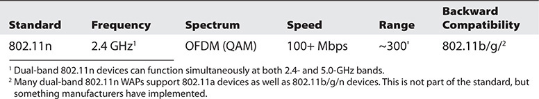
Table 14-5 802.11n Summary
802.11ac
802.11ac is a natural expansion of the 802.11n standard, incorporating even more streams, wider bandwidth, and higher speed. To avoid device density issues in the 2.4-GHz band, 802.11ac only uses the 5.0-GHz band. (See “What Wireless Is Already There?” later in this chapter for more on device density and how to deal with it.) Table 14-6 gives you the 802.11ac summary.

Table 14-6 802.11ac Summary
The latest versions of 802.11ac include a new version of MIMO called Multiuser MIMO (MU-MIMO). MU-MIMO gives a WAP the ability to broadcast to multiple users simultaneously.
NOTE For a broadcasting method, the 802.11n and 802.11ac devices use a special version of OFDM called quadruple-amplitude modulated (QAM).
WPS
By around 2006, 802.11 was everywhere and it was starting to get popular for non-PC devices such as printers, scanners, and speakers. The challenge with these devices was that they lacked any kind of interface to make it easy to configure the wireless settings.
To make configuration easier, the wireless industry created a special standard called Wi-Fi Protected Setup (WPS). WPS works in two modes: push button method or PIN method. (There were other modes, but they never were popular). With the push button method, you press a button on one device (all WPS-compatible devices have a physical or virtual push button) and then press the WPS button on the other device. That’s it. The two devices automatically configure themselves on an encrypted connection.
The PIN method was for connecting a PC to a WPS device (usually a WAP). You press the button on the WAP, locate the SSID on your device, and then enter an eight-digit PIN number as the WPA personal shared key (more on WPA shortly). All WPS WAPs have the PIN printed on the device.
WPS is very easy to use but is susceptible to different forms of WPS attacks. By design, the WPS PIN numbers are short. WPS attacks, therefore, concentrate on hacking the PIN number. By hacking the PIN, a bad actor can easily take control of the WAP, giving him or her access to the entire infrastructure. Use caution if you use WPS.
Wi-Fi Security
One of the biggest problems with wireless networking devices is that right out of the box they provide no security. Vendors go out of their way to make setting up their devices easy, so usually the only thing that you have to do to join a wireless network is turn your wireless devices on and let them find each other. Setting up an open Wi-Fi network is relatively simple. Once you decide to add security, on the other hand, you need to decide how you plan to share access with others.
EXAM TIP Expect a question about wireless authentication and authorization, comparing techniques and technologies between a shared or open network. The latter, of course, doesn’t have any authentication or authorization by default!
We need to use a number of techniques to make a wireless network secure, to harden it from malicious things and people. Wireless security is network hardening. (For details about network hardening techniques that apply to all kinds of networks, see Chapter 19, “Protecting Your Network.”)
NOTE All the methods used in wireless network security—authentication, encryption, MAC address filtering—can be considered network hardening techniques.
You also need to consider that your network’s data frames float through the air on radio waves instead of zipping safely along wrapped up inside network cabling. What’s to stop an unscrupulous network tech with the right equipment from grabbing those frames out of the air and reading that data?
To address these issues, 802.11 networks use three methods: MAC address filtering, authentication, and data encryption. The first two methods secure access to the network itself—access control—and the third secures the data that’s moving around the network. All three of these methods require you to configure the WAPs and wireless devices. Let’s take a look.
MAC Address Filtering
Most WAPs support MAC address filtering, a method that enables you to limit access to your network based on the physical addresses of wireless NICs. MAC address filtering creates a type of “accepted users” list—an access control list (ACL)—to restrict access to your wireless network. This is a common mitigation technique for undesired access to a network. A table stored in the WAP lists the MAC addresses that are permitted to participate in the wireless network, called a whitelist. Any network frames that don’t contain the MAC address of a node listed in the table are rejected.
EXAM TIP WAPs use an access control list (ACL) to enable or deny specific MAC addresses. Note that a WAP’s ACL has nothing to do with ACL in NTFS; it’s just the same term used for two different things.
Many WAPs also enable you to deny specific MAC addresses from logging onto the network, creating a blacklist. This works great in close quarters, such as apartments or office buildings, where your wireless network signal goes beyond your perimeter. You can check the WAP and see the MAC addresses of every node that connects to your network. Check that list against the list of your computers, and you can readily spot any unwanted interloper. Putting an offending MAC address in the “deny” column effectively blocks that system from piggybacking onto your wireless connection.
EXAM TIP MAC filtering with a whitelist means you allow only specific computers to join the network. When you deny specific computers, you create a blacklist. Whitelisting and blacklisting are labor-intensive processes, with whitelisting requiring far more work.
Although address filtering works, a hacker can very easily spoof a MAC address—make the NIC report a legitimate address rather than its own—and access the network. Worse, a hacker doesn’t have to connect to your network to grab your network traffic out of thin air!
If you have data so important that a hacker would want to get at it, you should seriously consider using a wired network or separating the sensitive data from your wireless network in some fashion.
Wireless Authentication
Implementing authentication enables you to secure a network so only users with the proper credentials can access network resources. Authentication in a wired network, as you’ll recall from Chapter 10, “Securing TCP/IP,” generally takes the form of a centralized security database that contains user names, passwords, and permissions, like the Active Directory in a Windows Server environment. Wireless network clients can use the same security database as wired clients, but getting the wireless user authenticated takes a couple of extra steps.
The first real 802.11 security standard was known as 802.11i. 802.11i addressed both authentication and encryption, but for right now let’s just discuss authentication under 802.11i. (Encryption under 802.11i is discussed a bit later in the “Data Encryption Using WPA” section.)
802.11i uses the IEEE 802.1X standard to enable you to set up a network with some seriously secure authentication using a RADIUS server and passwords encrypted with Extensible Authentication Protocol (EAP). Let’s look at the components and the process.
A RADIUS server stores user names and passwords, enabling you to set a user’s rights once in the network. A RADIUS server functions like a typical server, but the remote aspect of it requires you to learn new jargon. The terms “client” and “server” are so Active Directory, after all.
NOTE RADIUS stands for Remote Authentication Dial-In User Service. Say that five times.
Here’s how it works. The client wireless computer, called a supplicant, contacts the WAP, called a Network Access Server (NAS), and requests permission to access the network. The NAS collects the supplicant’s user name and password and then contacts the RADIUS server to see if the supplicant appears in the RADIUS server’s security database. If the supplicant appears and the user name and password are correct, the RADIUS server sends a packet back to the supplicant, through the WAP, with an Access-Accept code and an Authenticator section that proves the packet actually came from the RADIUS server. Then the remote user gets access to the network resources. That’s some serious security! See Figure 14-7.
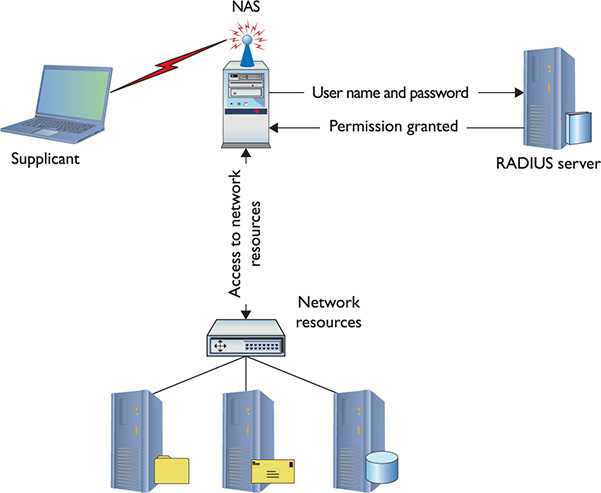
Figure 14-7 Authenticating using RADIUS
But here’s where it gets tricky. What are the points of potential security failure here? All over the place, right? The connection between each of these devices must be secure; several protocols make certain of that security. PPP, for example, provides a secure connection between the supplicant and the NAS. IPsec often provides the security between the NAS and the RADIUS server. We then need some form of authentication standard that encrypts all this authentication process. That’s where 802.11i calls for the Extensible Authentication Protocol (EAP). See Figure 14-8.
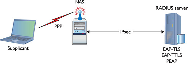
Figure 14-8 Authentication using RADIUS with protocols in place
EAP
One of the great challenges to authentication is getting the two ends of the authentication process to handle the many different types of authentication options. Even though PPP pretty much owned the user name/password authentication business, proprietary forms of authentication using smartcards/tokens, certificates, and so on, began to show up on the market, threatening to drop practical authentication into a huge mess of competing standards.
EAP was developed to create a single standard to allow two devices to authenticate. Despite the name, EAP is not a protocol in the classic sense, but rather it is a PPP wrapper that EAP-compliant applications can use to accept one of many types of authentication. Although EAP is a general-purpose authentication wrapper, its only substantial use is in wireless networks. EAP comes in various types, but currently only seven types are in common use:
• EAP-PSK Easily the most popular form of authentication used in wireless networks today, EAP-PSK (Pre-shared key) is nothing more than a shared secret code that’s stored on both the wireless access point and the wireless client, encrypted using the powerful AES encryption. (See the Encryption type field in Figure 14-9.) Note that CompTIA loses the hyphen, so preshared key.
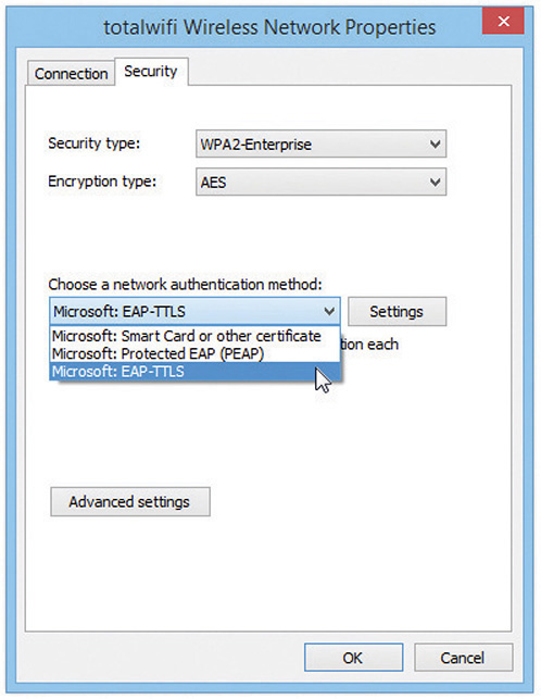
Figure 14-9 Setting EAP authentication scheme
• EAP-TLS EAP with Transport Layer Security (TLS) defines the use of a RADIUS server as well as mutual authentication, requiring certificates on both the server and every client. On the client side, a smart card may be used in lieu of a certificate. EAP-TLS is very robust, but the client-side certificate requirement is an administrative challenge. Even though it’s a challenge, the most secure wireless networks all use EAP-TLS. EAP-TLS is only used on wireless networks, but TLS is used heavily on secure Web sites.
• EAP-TTLS EAP-TTLS (Tunneled TLS) is similar to EAP-TLS but only uses a single server-side certificate. EAP-TTLS is very common for more secure wireless networks.
• EAP-MS-CHAPv2 More commonly known as Protected EAP (PEAP), EAP-MS-CHAPv2 uses a password function based on MS-CHAPv2 with the addition of an encrypted TLS tunnel similar to EAP-TLS. This is the most common implementation of EAP.
• EAP-MD5 This is a very simple version of EAP that uses only MD5 hashes for transfer of authentication credentials. EAP-MD5 is weak and the least used of all the versions of EAP described.
• LEAP Lightweight EAP (LEAP) is a proprietary EAP authentication used almost exclusively by Cisco wireless products. LEAP is an interesting combination of MS-CHAP authentication between a wireless client and a RADIUS server.
• EAP-FAST EAP Flexible Authentication via Secure Tunneling is Cisco’s replacement for LEAP. All current operating systems support EAP-FAST (assuming the right software is installed).
802.1X
EAP was a huge success and almost overnight gave those who needed point-to-point authentication a one-stop-shop methodology to do so. EAP was so successful that there was a cry to develop an EAP solution for Ethernet networks. This solution is called 802.1X. Whereas traditional EAP is nothing more than an authentication method wrapped in PPP, 802.1X gets rid of the PPP (Ethernet is not a point-to-point protocol!) and instead puts the EAP information inside an Ethernet frame.
802.1X is a port-based authentication network access control mechanism for networks. In other words, it’s a complete authentication standard designed to force devices to go through a full AAA process to get anywhere past the interface on a gateway system. Before 802.1X, a system on a wired network could always access another system’s port. Granted, an attacker wouldn’t be able to do much until he gave a user name/password or certificate, but he could still send packets to any computer on the network. This wasn’t good because it enabled attackers to get to the systems to try to do evil things. 802.1X prevented them from even getting in the door until they were authenticated and authorized.
The interesting part is that you already know about most of the parts of 802.1X because the standard worked hard to use existing technologies. From a distance, 802.1X looks a lot like a RADIUS AAA setup.
802.1X combines the RADIUS-style AAA with EAP versions to make a complete authentication solution. The folks who developed 802.1X saw it as a total replacement for every other form of authentication (even Kerberos), but the reality is that most people don’t like changing something that already works. To that end, only wireless networking broadly adopted 802.1X.
Data Encryption
The main way we secure a wireless network is by encrypting the data packets that are floating around. Encryption electronically scrambles data packets and locks them with an encryption key before transmitting them onto the wireless network. The receiving network device has to possess the decryption key to unscramble the packet and process the data. Thus, a hacker who grabs any data frames out of the air can’t read those frames unless he or she has the decryption key. Enabling wireless encryption through WPA2 provides a good level of security to data packets in transit.
NOTE The encryption/decryption works with both symmetric encryption, where both parties have the same key, and asymmetric encryption, where parties use public and private keys.
Over the years there have been a number of encryption methods for wireless. There was the original 802.11 (which was so bad it doesn’t even warrant discussion), WEP, WPA, and WPA2. There are additional features that tie encryption standards with authentication, such as WPA-PSK and WPA-Enterprise. Let’s cover all of these.
NOTE By the time you read this, WPA3 will have debuted (it was announced during this writing). WPA3 solves the problem with open Wi-Fi networks (think neighborhood café), creating individual security channels. Once you connect with your portable device, in other words, nothing can snoop on your communication.
Data Encryption Using WEP The granddaddy of wireless security, Wired Equivalent Privacy (WEP), uses a 64- or 128-bit encryption algorithm to scramble data frames. But even with the strongest encryption enabled, WEP isn’t a particularly robust security solution. In fact, WEP can be cracked in under a minute with just a regular laptop and open source software.
WEP is subject to many types of WEP attacks. Hackers can easily crack WEP, for two reasons: the size of the encryption key and the way the key is updated. First, the WEP keys were never really 64- and 128-bit. WEP uses an encryption cipher called RC4. There’s nothing inherently wrong with RC4, but RC4 is a stream cipher and needs a little code to start the encryption process, just like a water pump needs some water in the pump before it works. This extra code is stored in the key in the form of what’s called an initialization vector (IV). The IV with WEP is 24 bits, which means the encryption part of a WEP key is only 40-bit or 104-bit.
The second problem with WEP is that the encryption key is both static (never changes from session to session) and shared (the same key is used by all network nodes). This means it’s not that hard to crack assuming you can capture enough WEP-encrypted packets to figure out the code. WEP is simply a disaster.
WEP also fails to provide a mechanism for performing user authentication. That is, network nodes that use WEP encryption are identified by their MAC address, and no other credentials are offered or required. With just a laptop and some open source software, MAC addresses are very easy to sniff out and duplicate, thus opening you up to a possible spoofing attack. (See Chapter 19, “Protecting Your Network,” for the scoop on spoofing and other common attacks.)
The key thing (pun intended) to remember about WEP is that it is outdated and should never be used. The only security WEP provides today is to prevent casual people from connecting to your WAP. Its encryption is so easily cracked that you might as well be transmitting plaintext. WEP is like a No Trespassing sign on a post, but without the fence. Modern WAPs don’t offer WEP as an option.
Data Encryption Using WPA The 802.11i standard was designed to address the problems with WEP and to provide proper authentication. The full standard took a while to complete, so the wireless industry implemented an intermediate fix. They invented a sales term called Wi-Fi Protected Access (WPA) that adopted most (not all) of the 802.11i standard, fixing some of the weaknesses of WEP. WPA offers security enhancements such as dynamic encryption key generation (keys are issued on a per-user and per-session basis) and an encryption key integrity-checking feature.
WPA works by using an extra layer of security, called the Temporal Key Integrity Protocol (TKIP), around the WEP encryption scheme. It’s not, therefore, a complete replacement protocol for WEP and still uses RC4 for cipher initialization—hence the name TKIP-RC4. TKIP added a 128-bit encryption key that seemed unbreakable when first introduced. Within four years of introduction, however, researchers showed methods by which hackers could waltz through WPA security almost as quickly as through WEP security. Another solution had to be found.
Data Encryption Using WPA2 The IEEE 802.11i standard amended the 802.11 standard to add much-needed security features. I already discussed the 802.1X authentication measure using EAP to provide secure access to Wi-Fi networks. 802.11i also replaced TKIP-RC4 with the much more robust CCMP-AES, a 128-bit block cipher that’s much tougher to crack.
NOTE CCMP stands for Counter Mode Cipher Block Chaining Message Authentication Code Protocol. Whew! That’s why we commonly just use the initials, CCMP. AES stands for Advanced Encryption Standard.
Implementing the full 802.11i standard took time because most of the installed Wi-Fi hardware couldn’t be updated to handle AES encryption. WPA held the title of “most secure wireless” for a number of years.
Eventually, enough devices were made that could support AES that the full 802.11i standard was implemented under the sales term Wi-Fi Protected Access 2 (WPA2). A “WPA2-compliant device” is really just a marketing term for a device that fully supports the 802.11i standard. WPA2 is the current top security standard used on 802.11 networks. WPA2 is not hack-proof, but it definitely offers a much tougher encryption standard that stops the casual hacker cold.
The most common way to set up WPA or WPA2 encryption is to use a simple version called WPA (or WPA2) Pre-shared key (PSK). Basically, with these PSK versions, you create a secret key that must be added to any device that is going to be on that SSID. There is no authentication with WPA-PSK or WPA2-PSK.
WPA attacks and WPA2 attacks can happen, especially with wireless networks using WPA-Personal or WPA2-Personal passphrases. The attacks take place by using sophisticated methods that make a number of assumptions about the passphrase, and the fact that certain passphrases are used quite often. The most important thing to do to prevent these attacks from succeeding is to use long passphrases (16 or more characters), thus making the network hard to crack. Otherwise, you need authentication. If you want authentication you move into what most wireless folks will call an enterprise setup. For example, when you use a RADIUS server for authentication with WPA2 to create an amazingly secure wireless network, it gets a fancy name: WPA2-Enterprise. Let’s talk about enterprise wireless a bit more.
Enterprise Wireless
A simple BSSID or ESSID is incredibly easy to set up. You can take a few cheap WAPs from your local electronics store, connect them to a switch, use a Web interface to configure each WAP, and start connecting clients. Inexpensive SOHO WAPs and wireless routers have been around so long—almost as long as 802.11 itself—that for many of us this is what we think a “wireless network” means.
But as wireless networks become more important, complex, and busy, the cheap SOHO boxes just aren’t going to work anymore. When you want dependable, robust, secure, administrable wireless networks, you need enterprise-class wireless equipment. In general, an enterprise wireless device differs from a SOHO device in five areas: robust device construction, centralized management, VLAN pooling, Power over Ethernet, and bringing personal wireless devices into the enterprise environment.
Robust Device Construction
If you compare a typical SOHO WAP to an enterprise WAP, you’ll notice immediately that the enterprise WAP is made of better materials (often metal instead of plastic). Enterprise WAPs for the most part will also be more configurable. Most enterprise WAPs enable you to swap out antennas and radios, so you can keep WAPs while upgrading them to the latest technologies. Figure 14-10 shows an enterprise WAP.
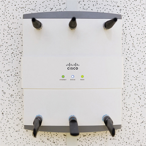
Figure 14-10 Cisco Enterprise WAP
Enterprise Wireless Administration
An enterprise wireless infrastructure is almost certainly going to consist of a large number of WAPs. It’s impossible to administer a large number of WAPs when you have to access each WAP individually. Imagine something as simple as changing the password on a WPA2-encrypted ESSID on a wireless network with 50+ WAPs (Figure 14-11). The job would take forever!
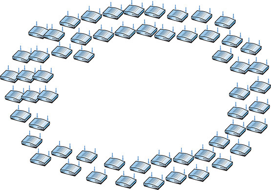
Figure 14-11 Configuring WAPs
The wireless industry long ago appreciated the complexity of enterprise-level wireless networks and created tools to make administration easier. The important point to any wireless network is that all of the WAPs, at least on a single SSID, connect to a single switch or group of switches. What if we offload the job of configuration to a switch that’s designed to handle a number of WAPs simultaneously? We call these switches wireless controllers (Figure 14-12).
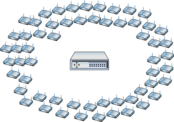
Figure 14-12 Wireless controller
NOTE Wireless controllers have a number of other names, such as wireless switch, wireless LAN switch, and so forth.
Any WAP that you can access directly and configure singularly via its own interface is called a thick client. A WAP that can only be configured by a wireless controller is called a thin client. For years, these centralized configuration methods were proprietary for each wireless manufacturer, making for little or no cross-brand interoperability. This incompatibility in thin and thick clients was a common wireless issue back in the day. Today, most manufacturers use the Lightweight Access Point Protocol (LWAPP) to ensure interoperability. Given LWAPP’s broad acceptance, most WAPs will accept commands from any wireless controller.
VLAN Pooling
One of the big challenges to larger enterprise networks is the large number of clients that might be on a single SSID at any given moment. As the number of devices grows, you get a huge amount of broadcasts on the network. The traditional method to reduce this is to divide the WLAN into multiple broadcast domains and use routers to interconnect the domains. In many cases, though, the needs of the wireless network require a single domain; instead we create a pool of VLANs for a single SSID and randomly assign wireless clients to one of the VLANs. This is called VLAN pooling.
Power over Ethernet
Wireless access points need electrical power, but they’re invariably placed in strange locations (like ceilings or high up on walls) where providing electrical power is not convenient. No worries! Better WAPs support an IEEE standard (802.3af) called Power over Ethernet (PoE), which enables them to receive their power from the same Ethernet cables that transfer their data. The switch that connects the WAPs must support PoE, but as long as both the WAP and the switches to which they connect support PoE, you don’t have to do anything other than just plug in Ethernet cables. PoE works automatically. As you might imagine, it costs extra to get WAPs and switches that support PoE, but the convenience of PoE for wireless networks makes it a popular option.
The original PoE standard came out in 2003 with great response from the industry. Its popularity revealed a big problem: the original 802.3af standard only supported a maximum of 14.4 watts of DC power and many devices needed more. In 2009, 802.3af was revised to output as much as 25.5 watts. This new PoE amendment to 802.3 is called 802.3at, PoE plus, or PoE+.
Implementing Wi-Fi
Installing and configuring a Wi-Fi network requires a number of discrete steps. You should start with a site survey to determine any obstacles (existing wireless, interference, and so on) you need to overcome and to determine the best location for your access points. You’ll need to install one or more access points, and then configure both the access point(s) and wireless clients. Finally, you should put the network to the test, verifying that it works as you intended.
Performing a Site Survey
As mentioned, the first step of installing a wireless network is the site survey. A site survey will reveal any obstacles to creating the wireless network and will help determine the best possible location for your access points. The main components for creating a site survey are a floor plan of the area you wish to provide with wireless and a site survey tool such as NETSCOUT’s AirMagnet Survey Pro (Figure 14-13). Wireless survey tools help you discover any other wireless networks in the area and will integrate a drawing of your floor plan with interference sources clearly marked. This enables you to get the right kind of hardware you need and makes it possible to get the proper network coverage.
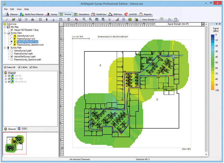
Figure 14-13 AirMagnet Survey Pro
What Wireless Is Already There?
Discovering any wireless network signals other than your own in your space enables you to set both the SSID and channel to avoid networks that overlap. One part of any good site survey is a wireless analyzer. A wireless analyzer or Wi-Fi analyzer is any device that looks for and documents all existing wireless networks in the area. Wireless analyzers are handy tools that are useful for diagnosing wireless network issues and conducting site surveys. You can get dedicated, hand-held wireless analyzer tools or you can run site survey software on a laptop or mobile wireless device. Wireless survey tools like AirMagnet Survey Pro always include an analyzer as well. Figure 14-14 shows a screenshot of Acrylic WiFi, a free and popular wireless analyzer.
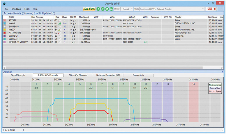
Figure 14-14 Acrylic WiFi

SIM Check out the excellent Chapter 14 Show! Sim about third-party wireless utilities at http://totalsem.com/007. It’s a cool sim about non-Microsoft implementations.
Wireless networks send out radio signals on the 2.4- or 5.0-GHz spectrum using one of a number of discrete channels. In early wireless networks, a big part of the setup was to determine the channels used nearby in order to avoid them. In more modern wireless networks, we rarely adjust channels manually anymore. Instead we rely on powerful algorithms built into WAPs to locate the least congested channels automatically. The bigger challenge today is the preexistence of many Wi-Fi networks with lots of clients, creating high device density environments. You need a wireless solution that handles many users running on the few wireless frequencies available.
There are plenty of tools like AirMagnet Survey Pro to support a wireless survey. All good survey utilities share some common ways to report their findings. One of the most powerful reports that they generate is called a heat map. A heat map is nothing more than a graphical representation of the RF sources on your site, using different colors to represent the intensity of the signal. Figure 14-15 shows a sample heat map.
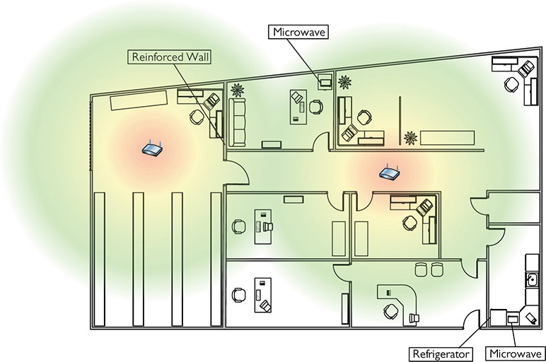
Figure 14-15 Site survey with heat map
Interference Sources
It might seem like overkill in a small network, but any network beyond a simple one should have a sketched-out site survey with any potential interference sources clearly marked (Figure 14-16). Refrigerators, reinforced walls, metal plumbing, microwave ovens; all of these can create horrible dead spots where your network radio wave can’t easily penetrate. With a difficult or high-interference area, you might need to move up to 802.11n or 802.11ac equipment with three or four antennas just to get the kind of coverage you want. Or you might need to plan a multiple WAP network to wipe out the dead zones. A proper site survey gives you the first tool for implementing a network that works.
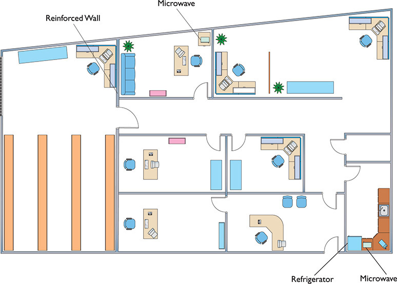
Figure 14-16 Site survey with interference sources noted
Installing the Client
Because every Wi-Fi network needs clients (otherwise, what’s the point?), you need to install Wi-Fi client hardware and software. Pretty much every type of mobile device (smartphones, laptops, tablets, and so forth) comes with a built-in client, usually part of the operating system.
Desktop systems are a different story. Most desktops don’t have built-in wireless, so you’ll need to install a wireless NIC. You have a choice between installing a PCIe card or a USB device. With a PCIe NIC, power down the PC, disconnect from the AC source, and open the case. Following good CompTIA A+ technician procedures, locate a free slot on the motherboard, remove the slot cover, remove the NIC from its antistatic bag, install the NIC, and affix the retaining screw. See Figure 14-17. Often you’ll need to attach the antenna. Button everything up, plug it in, and start the computer. If prompted, put in the disc that came from the manufacturer and install drivers and any other software necessary.
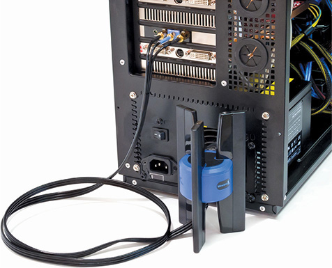
Figure 14-17 Wi-Fi NIC installed
With a USB NIC, you should install the drivers and software before you connect the NIC to the computer. This is standard operating procedure for any USB device, as you most likely recall from your CompTIA A+ certification training (or from personal experience).
Setting Up an Ad Hoc Network
Although ad hoc networks are rare, they are on the CompTIA Network+ exam. Plus, you might need to set one up in the real world, so let’s look at the process.
Configuring NICs for ad hoc mode networking requires you to address four things: SSID, IP addresses, channel, and sharing. (Plus, of course, you have to set the NICs to function in ad hoc mode!) Each wireless node must be configured to use the same network name (SSID). It’s common for one system to set up an ad hoc node and then have other nodes attach to that node. Of course, no two nodes can use the same IP address, although this is unlikely because all operating systems use Automatic Private IP Addressing (APIPA). Finally, ensure that the File and Printer Sharing service is running on all nodes. Figure 14-18 shows a wireless network configuration utility with ad hoc mode selected.
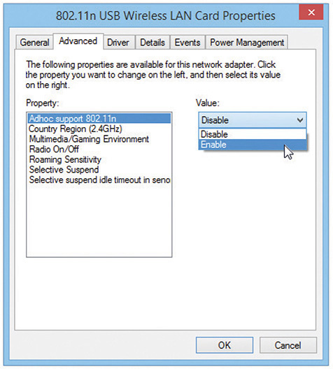
Figure 14-18 Selecting ad hoc mode in a wireless configuration utility
Setting Up an Infrastructure Network
Site survey in hand and Wi-Fi technology selected, you’re ready to set up a wireless network in infrastructure mode. You need to determine the optimal location for your WAP, configure the WAP, and then configure any clients to access that WAP. Seems pretty straightforward, but the devil, they say, is in the details.
Placing the Access Points/Antennas
All wireless access points have antennas that radiate the 802.11 signal to the clients, so the optimal location for a WAP depends on the area you want to cover and whether you care if the signal bleeds out beyond the borders. You also need to use antennas that provide enough signal and push that signal in the proper direction. There are some interesting options here and you should know them both for modern networking and for the CompTIA Network+ exam.
Antenna placement on the WAPs is also very important. WAP antennas come in many shapes and sizes. In the early days it was common to see WAPs with two antennas (Figure 14-19). Some WAPs have only one antenna and some (802.11n and 802.11ac) have more than two, like the one you saw in Figure 14-3. Even a WAP that doesn’t seem to have antennas is simply hiding them inside the case.
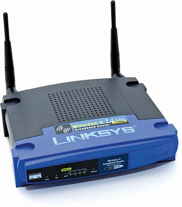
Figure 14-19 WRT54G showing two antennas
There are three basic types of antennas common in 802.11 networks: omnidirectional, unidirectional, and patch. Each offers different solutions for coverage of specific wireless network setups. Let’s look at all three.
Omnidirectional In general, an omnidirectional antenna radiates the signal outward from the WAP in all directions. For a typical network, you want blanket coverage and would place a WAP with an omnidirectional antenna in the center of the area (Figure 14-20). This has the advantage of ease of use—anything within the signal radius can potentially access the network. The standard straight-wire antennas that provide the most omnidirectional function are called dipole antennas.
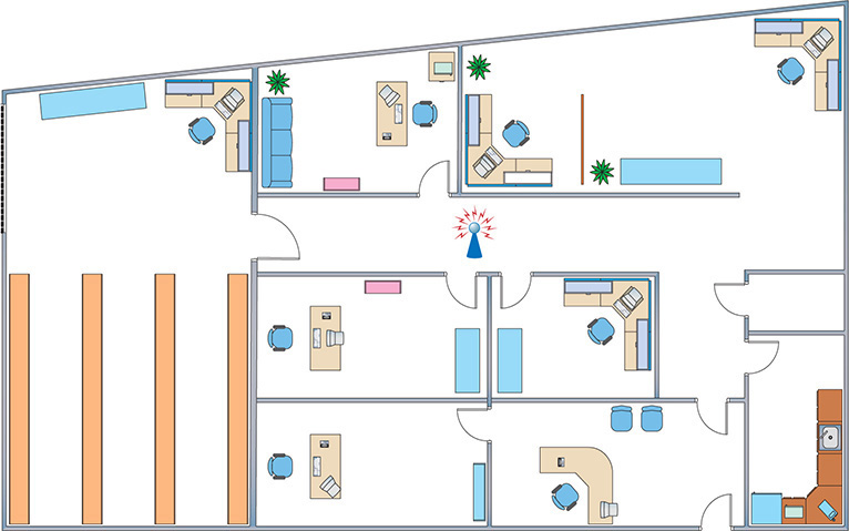
Figure 14-20 Office layout with WAP in the center
The famous little black antennas seen on older WAPs are all dipoles. A dipole antenna has two radiating elements that point in opposite directions. But if you look at a WAP antenna, it looks like it only points in one direction (Figure 14-21). If you open up one of these antennas, however, you’ll see that it has two opposing radiating elements (Figure 14-22).
![]()
Figure 14-21 Typical WAP dipole antenna—where are the two elements?
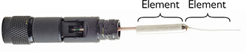
Figure 14-22 Same antenna from Figure 14-21 opened, showing the two elements
A dipole antenna doesn’t radiate in a perfect ball. It actually is more of a doughnut shape, as shown in Figure 14-23. Note that this shape is great for outdoors or a single floor, but it doesn’t send much signal above or below the WAP.
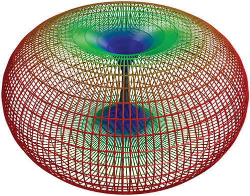
Figure 14-23 Dipole radiation pattern
The omnidirectional and centered approach does not work for every network, for three reasons. First, if the signal exceeds the size of the network space, that signal bleeds out. The signal can bleed out a lot in some cases, particularly if your specific space doesn’t allow you to put the WAP in the center, but rather off-center. This presents a security risk as well, because someone outside your network space could lurk, pick up the signal, and do unpleasant things to your network. Second, if your network space exceeds the signal of your WAP, you’ll need to get some sort of signal booster. Third, any obstacles will produce glaring dead spots in network coverage. Too many dead spots make a less-than-ideal solution. To address these issues, you might need to turn to other solutions.
An antenna strengthens and focuses the RF output from a WAP. The ratio of increase—what’s called gain—is measured in decibels (dB). The gain from a typical WAP is 2 dB, enough to cover a reasonable area, but not a very large room. Increasing the signal requires a bigger device antenna. Many WAPs have removable device antennas. To increase the signal in an omnidirectional and centered setup, simply replace the factory device antennas with one or more bigger device antennas (Figure 14-24). Get a big enough antenna and you can crank it all the way up to 11!
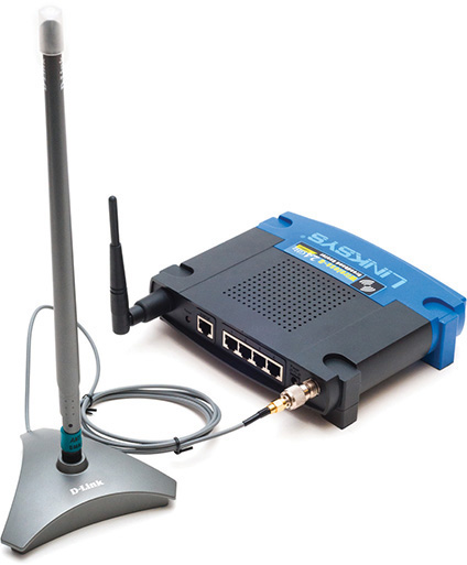
Figure 14-24 Replacement antenna on a WAP
Unidirectional When you don’t necessarily want to broadcast to the world, you can use one or more directional antennas to create a nicely focused network. A unidirectional antenna, as the name implies, focuses a radio wave into a beam of sorts. Unidirectional antennas come in a variety of flavors, such as parabolic, dish, and Yagi, to name a just a few. A parabolic antenna looks like a satellite dish. A Yagi antenna (named for one of its Japanese inventors) is often called a beam antenna and can enable a focused radio wave to travel a long way, even miles (Figure 14-25)! If you need to connect in a narrow beam (down a hallway or from one faraway point to another), unidirectional antennas are the way to go.
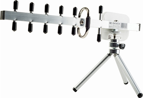
Figure 14-25 Yagi antenna
Patch Antennas Patch antennas are flat, plate-shaped antennas that generate a half-sphere beam. Patch antennas are always placed on walls. The half-sphere is perfect for indoor offices where you want to fill the room with a strong signal but not broadcast to the room behind the patch (Figure 14-26).
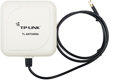
Figure 14-26 Patch antenna
Optimal Antenna Placement Optimal antenna placement varies according to the space to fill and security concerns. You can use the site survey and the same wireless analyzer tools to find dead spots, odd corners, and so on. Use the right kind of antenna on each WAP to fill in the space.
Configuring the Access Point
Wireless access points have a browser-based setup utility. Typically, you fire up the Web browser on one of your network client workstations and enter the access point’s default IP address, such as 192.168.1.1, to bring up the configuration page. You need to supply an administrative password, included with your access point’s documentation, to log in (Figure 14-27).
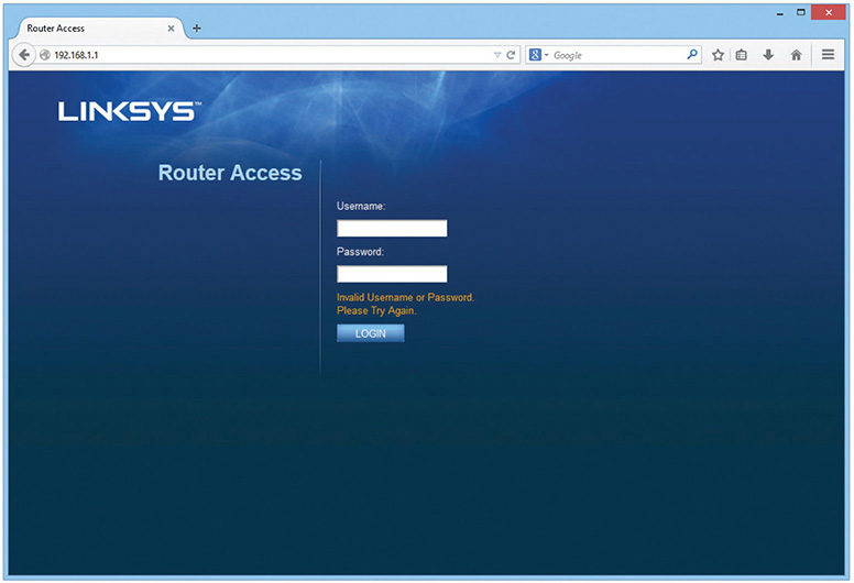
Figure 14-27 Security login for Linksys WAP
Once you’ve logged in, you’ll see configuration screens for changing your basic setup, access point password, security, and so on. Different access points offer different configuration options. Figure 14-28 shows the initial setup screen for a popular Linksys WAP/router.
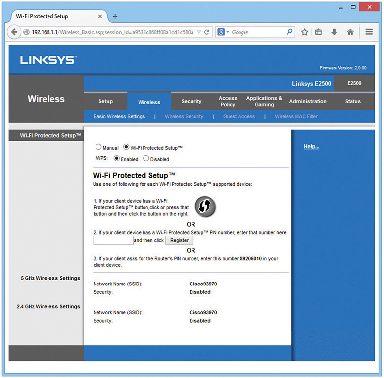
Figure 14-28 Linksys WAP setup screen
Configuring the SSID and Beacon The SSID option is usually located somewhere obvious on the configuration utility. On the Linksys model shown in Figure 14-28, this option is on the Setup tab. Configure your SSID to something unique.
The primary way we locate wireless networks is by using our clients to scan for SSIDs. All wireless networks have a function to turn off the SSID broadcast. You can choose not to broadcast the SSID, but this only stops casual users—sophisticated wireless intruders have tools to detect networks that do not broadcast their SSIDs. Turning off SSID broadcast forces users to configure the connection to a particular SSID manually.
Aside from the SSID, broadcast traffic includes the beacon, essentially a timing frame sent from the WAP at regular intervals. The beacon frame enables Wi-Fi networks to function, so this is fairly important. Beacon traffic also makes up a major percentage of network traffic because most WAPs have beacons set to go off every 100 ms! You can adjust the rate of the beacon traffic down and improve your network traffic speeds, but you lower the speed at which devices can negotiate to get on the network, among other things. Figure 14-29 shows the Beacon Interval setting on a Linksys router.
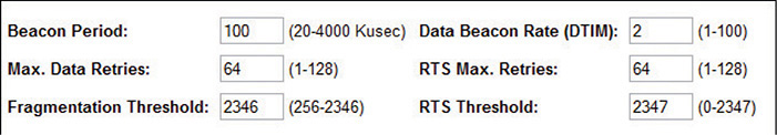
Figure 14-29 Setting the beacon interval
Configuring MAC Address Filtering Increase security even further by using MAC address filtering to build a list of wireless network clients that are permitted or denied access to your wireless network based on their unique MAC addresses. Figure 14-30 shows the MAC address filtering configuration screen on a Linksys WAP. Simply enter the MAC address of a wireless node that you want to allow or deny access to your wireless network.
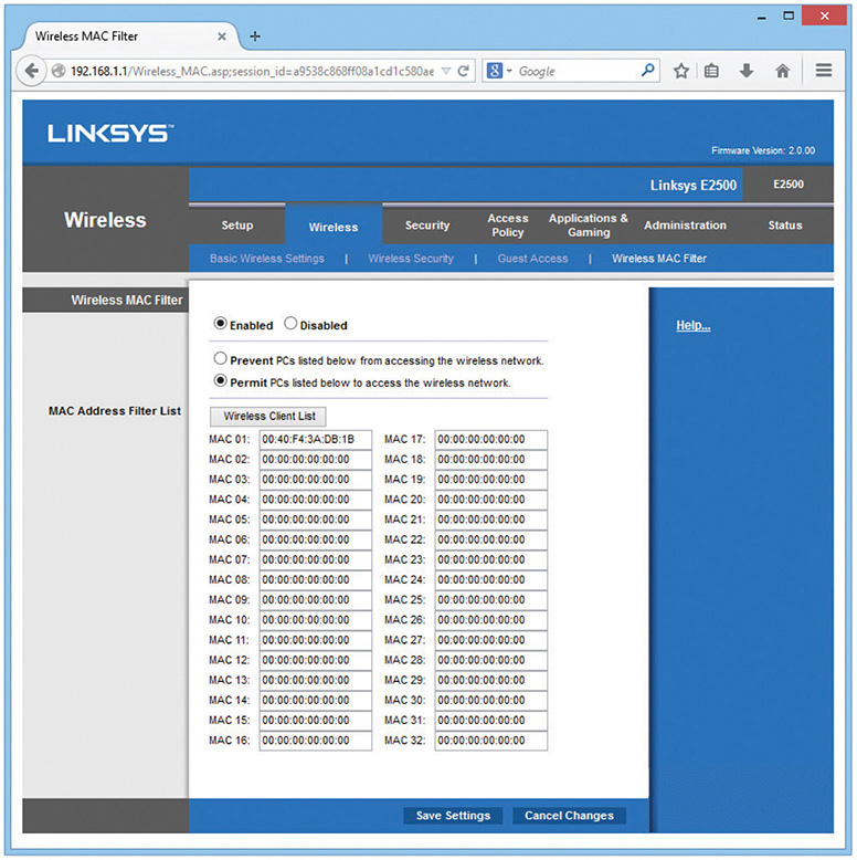
Figure 14-30 MAC address filtering configuration screen for a Linksys WAP
Configuring Encryption Enabling encryption ensures that data frames are secured against unauthorized access. To set up encryption, you turn on encryption at the WAP and generate a unique security key. Then you configure all connected wireless nodes on the network with the same key information. Figure 14-31 shows the WPA2 key configuration screen for a Linksys WAP.
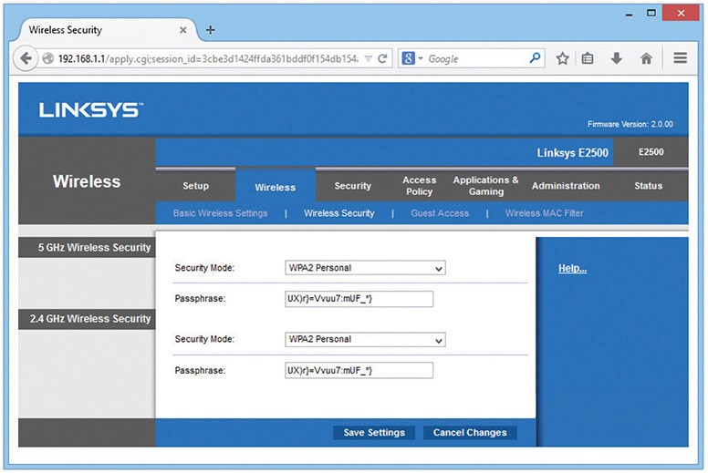
Figure 14-31 Encryption key configuration screen on Linksys WAP
You can generate a set of encryption keys either automatically or manually. You can save yourself a certain amount of effort by using the automatic method. Select an encryption level—the usual choices are either 64-bit or 128-bit—and then enter a unique passphrase and click the Generate button (or whatever the equivalent button is called in your WAP’s software). Then select a default key and save the settings.
The encryption level, key, and passphrase must match on the wireless client node or communication fails. Many access points have the capability to export the encryption key data onto removable media for easy importing onto a client workstation, or you can configure encryption manually using the vendor-supplied configuration utility, as shown in Figure 14-32.
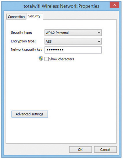
Figure 14-32 Encryption screen on client wireless network adapter configuration utility
If you have the option, choose WPA2 encryption for both the WAP and the NICs in your network. You configure WPA2 the same way you would WPA. Note that the settings such as WPA2 for the Enterprise assume you’ll enable authentication using a RADIUS server (Figure 14-33). Always use the strongest encryption you can. If you have WPA2, use it. If not, use WPA. WEP is always a terrible choice.
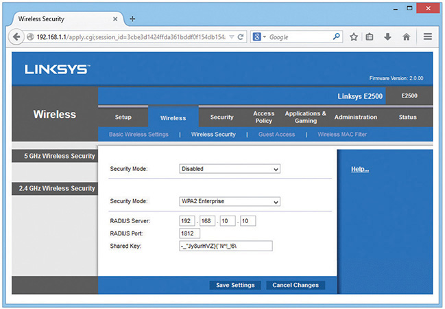
Figure 14-33 Encryption screen with RADIUS option
Configuring Channel and Frequency With most home networks, you can simply leave the channel and frequency of the WAP at the factory defaults, but in an environment with overlapping Wi-Fi signals, you’ll want to adjust one or both features. Using a wireless analyzer, see current channel utilization and then change your channel to something that doesn’t conflict. To adjust the channel, find the option in the WAP configuration screens and simply change it. Figure 14-34 shows the channel option in a Linksys WAP.
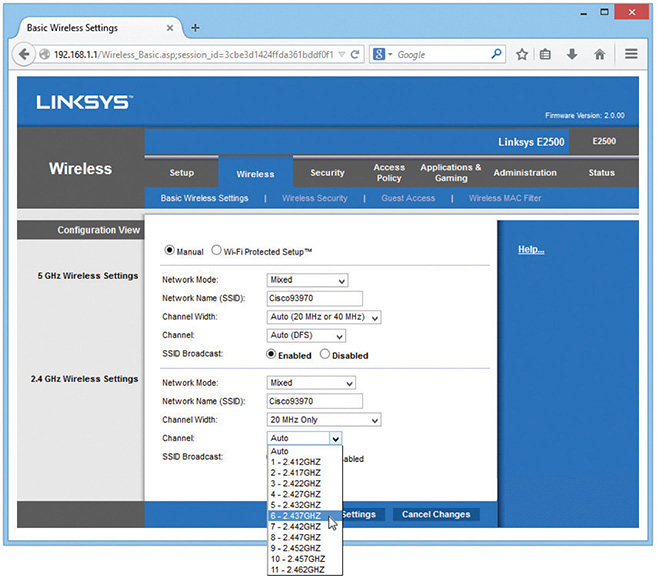
Figure 14-34 Changing the channel
With dual-band 802.11n WAPs, you can choose which band to put 802.11n traffic on, either 2.4 GHz or 5.0 GHz. In an area with overlapping signals, most of the traffic will be on the 2.4-GHz frequency because most devices are either 802.11b or 802.11g. You can avoid any kind of conflict with your 802.11n devices by using the 5.0-GHz frequency band instead. Figure 14-35 shows the configuration screen for a dual-band 802.11n WAP.
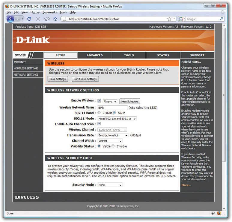
Figure 14-35 Selecting frequency
Configuring the Client
As with ad hoc mode wireless networks, infrastructure mode networks require that the same SSID be configured on all nodes and access points. Normally, the client would pick up a broadcast SSID and all you need to do is type in the security passphrase or encryption key. With nonbroadcasting networks, on the other hand, you need to type in a valid SSID as well as the security information (Figure 14-36).
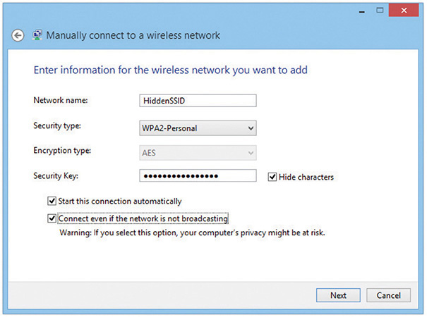
Figure 14-36 Typing in an SSID manually
The important thing to remember is that once you successfully connect to a wireless network, your client will store the settings for that client in a profile. From now on, whenever the client sees a particular SSID, your device will automatically try to connect to that SSID using the encryption and key stored in the profile. Of course, if the wireless network changes in any way—for example, if the encryption password is changed—you won’t be able to access the network unless you delete the profile and reacquire the wireless network.
Extending the Network
Creating a Basic Service Set network with a single WAP and multiple clients works in a relatively small area, but you can extend a Wi-Fi network in a few ways if you have difficult spaces—with lots of obstructions, for example—or a need to communicate beyond the ~300-foot range of the typical wireless network. Most commonly, you’d add one or more WAPs to create an Extended Service Set. You can also install a wireless bridge to connect two or more wired networks.
Many companies make wireless range extenders, devices that pick up your Wi-Fi signal and rebroadcast it. Some look like a WAP; other models plug directly into an electrical outlet. Current wireless range extenders require very little setup and can extend your network between floors and into dead spots.
Adding a WAP
To add a WAP to a Wi-Fi network, you’ll need to run a cable from a switch on the network to where you want to install it. Configuration is pretty straightforward. Both WAPs require the same ESSID, and if the WAPs are near each other, use separate channels.
Wireless Bridges
Dedicated wireless bridges are used to connect two wired networks together, or to join wireless and wired networks together in the same way that wired switches do.
Wireless bridges come in two different flavors: point-to-point and point-to-multipoint. Point-to-point bridges can only communicate with a single other bridge and are used to connect two wired network segments. Point-to-multipoint bridges can talk to more than one other bridge at a time and can connect multiple network segments. Figure 14-37 shows a wireless bridge.
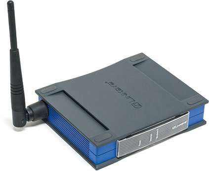
Figure 14-37 Linksys wireless bridge device
Verifying the Installation
Once you’ve completed the initial installation of a Wi-Fi network, test it. Move some traffic from one computer to another using the wireless connection. Never leave a job site without verifying the installation.
Troubleshooting Wi-Fi
Wireless networks are pretty magical when they work right, but the nature of no wires often makes them vexing things to troubleshoot when they don’t.
As with any troubleshooting scenario, your first step in troubleshooting a wireless network is to break down your tasks into logical steps. First, figure out the scope of the wireless networking problem. I like to break wireless problems into three symptom types:
• You can’t get on the wireless network. Your client (or clients) may or may not think it’s connected, but you can’t access shared resources (Web pages, remote folders, and so on).
• Your wireless connections are way too slow. Your clients are accessing shared resources.
• Your wireless connection is doing weird things.
CompTIA Network+ objective 5.4 says “Given a scenario, troubleshoot common wireless connectivity and performance issues” and then lists a large number of issues. You can bet good money that CompTIA will give you one or more scenario questions that mention one or more of these issues. Every one of these issues will fit into the three symptoms I just listed. So let’s use these symptoms as a tool to organize how you will address these scenarios on the exam (and in the real world as well).
No Connection
Wi-Fi networks want to connect. You rarely if ever get an error on a device that says “You may not speak to WAP55 that is supporting SSID X.” Instead, you get more subtle errors such as repeated prompts for passwords, APIPA addresses, and such.
EXAM TIP Be prepared for scenario questions that quiz you about the limits of the wireless standards. This includes throughput speeds (11-, 54-, 100+-Mbps), frequencies, distances, and channel usage. See the standards discussion earlier in the chapter for the limitations of each standard.
Channel Problems
If you’re working with one of the older 802.11 versions using the 2.4-GHz channel, you may have problems with channels. One issue is channel overlap, where 2.4-GHz channels overlap with their nearest channel neighbors. For example, channel 3 overlaps with channels 1, 2, 4, and 5. Some folks make the mistake of configuring an SSID and setting each WAP only one channel apart. This will lead to connection problems, so always try to stick to using channels 1, 6, and 11 only. Frequency mismatch, where you set the SSID information correctly but a device is using a different channel than the WAP, may still take place. However, automatic channel selection is now the norm and mismatched channels are extremely rare. If you suspect this is a problem, set your wireless device to auto channel selection.
EXAM TIP You can use wireless scanning tools to check for wireless channel utilization. These are software tools that give you metrics and reports about nearby devices and which one is connected to which WAP. These tools enable you to discover overworked WAPs, saturated areas, and so on, so you can deploy WAPs to optimize your network.
Security Type Mismatch
The CompTIA objectives use the term security type mismatch to define one of two things: either you’ve connected manually to a wireless network and have set up the incorrect encryption type, or you’ve automatically accessed a particular SSID and entered the wrong passphrase. Entering the wrong encryption type is rare, only happening when you set up a wireless connection manually. However, entering the wrong passphrase is the classic no-errors-but-won’t-work issue. In older operating systems, you often would only get one chance to enter a key and if you failed your only clue was that your client got an APIPA/zeroconf address. More modern operating systems say something clearer, such as a message like wrong passphrase. Pretty much every wireless NIC is set to DHCP and if you don’t have the right password your client won’t get past the WAP to talk to anything on the network, including the DHCP server.
• Symptoms: not on network, continual prompting for password, APIPA/zeroconf address
• Solution: Enter the correct password
Signal/Power Levels
802.11 is a low-power radio and has a limited range. If the WAP doesn’t have enough power, you’ll have signal attenuation and your device won’t be able to access the wireless network. All of the 802.11 standards have distance limitations; exceeding those limitations will reduce performance. Certainly a quick answer is to move closer to the WAP, but there are a number of issues that cause power levels to drop too low to connect beyond the obvious “you’re too far away” from the WAP.
NOTE Interference can also cause signal loss, but I choose to treat this as a separate issue later in this section. For now, we are talking about simple signal loss due to insufficient power.
If your WAP lacks enough signal power you have five choices: get closer to the WAP, avoid physical issues, turn up the power, use a better antenna, or upgrade to a newer 802.11 version (like 802.11ac) with features that enable them to use the power they have more efficiently. I’m going to skip moving closer to the WAP as that’s a bit obvious, but let’s cover the other four.
A physical issue is what it sounds like, something physical in the way keeps the signal from reaching its destination. When installing a network, you must watch out for concrete walls, metal (especially metal studs), and the use of special RF-blocking window film. The solution is more careful planning of WAP placement and realizing that even in the best-planned environment it is not at all uncommon to move WAPs based on the need to clear dead spots. We’ll cover more about physical issues later in this chapter.
Increasing the power is not that hard to do, depending on the wireless device. Most WAP manufacturers set their radio power levels relatively low out of the box. A few manufacturers—a great example is Cisco on their high-end WAPs—enable you to increase or to decrease the power (Figure 14-38). Sadly, very few low-end/SOHO devices have a method to increase radio power using the OEM interface. If you’re willing to gamble, however, you should be able to find a third-party firmware such as OpenWrt which, on certain devices, gives you this capability.
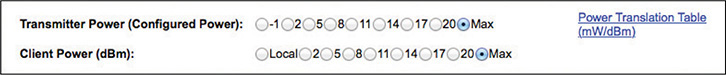
Figure 14-38 Increasing power on a Cisco WAP
Too many 802.11 installations ignore the antennas, dropping in WAPs using their default antennas. In most cases the omnidirectional antennas that come with WAPs are very good—which is why they are so often the default antennas—but in many cases they are simply the incorrect antenna type and need to be replaced. If you’re losing signal, don’t forget to consider if the antenna is wrong for the wireless setup. Watch for scenarios on the CompTIA Network+ exam where replacing an omnidirectional antenna with one or more unidirectional antennas makes an easy fix. Also, look for incorrect antenna placement, where moving a few inches away from an obstacle can make big changes in performance.
The last power/signal issue is the fact that the MIMO features in 802.11n and 802.11ac are absolutely amazing in their ability to overcome dead spots and similar issues that on earlier versions of 802.11 can only be fixed with aggressive tweaking of WAP locations and antenna types. While MIMO and MU-MIMO aren’t only to increase signal distance, it’s almost certain you’ll see a scenario where simply updating WAPs to 802.11n or 802.11ac will automatically fix otherwise tricky problems.
Slow Connection
Slow wireless connections are far more difficult to troubleshoot than no connection at all. Unlike a disconnection, where you have obvious and clear clues, a slowdown is just…slow. In these situations, you are clearly connected to an SSID, you have a good IP address, and the client itself runs well; but data transfer is slow: Web pages load slowly, applications time out, and you sense a general, hard-to-measure, irritating slowness.
NOTE There are plenty of reasons for a device to run slowly that have nothing to do with wireless. Don’t forget issues such as insufficient RAM, malware, and so forth.
In general you can trace the cause of this slowness to one of three issues: either you have too many devices overworking your WAPs; there are physical problems with signals going between your WAP and your clients; or there is too much RFI on the network. Let’s look at these three issues.
Overworked WAPs
An individual WAP has a very specific amount of bandwidth that depends on the version of 802.11 and the way it is configured. Once you hit the maximum bandwidth, you’re going to have network slowdowns as the overworked WAP tries to handle all of the incoming wireless connections.
We overwork WAPs in many different ways, but one of the most common is by attaching too many devices to a single SSID over time, what’s called device saturation. This creates overcapacity issues, such as slow speeds and inability to connect to the network. Avoid device saturation by adding more capacity. Careful placement of extra WAPs in high-demand areas is a huge step in the right direction. Usually the best, but most expensive, method is to upgrade your hardware: leaping from the 802.11g to the 802.11ac standard alone makes a massive difference in eliminating device saturation.
Jitter is the loss of packets due to an overworked WAP. Jitter shows up as choppy conversations over a video call, strange jumps in the middle of an online game—pretty much anything that feels like the network has missed some data. Latency is when data stops moving for a moment due to a WAP unable to do the work. This manifests as a Word document that stops loading, for example, or an online file that stops downloading.
Speaking of 802.11ac, the biggest single issue causing device saturation is the imbalance of many devices using the 2.4-GHz band versus few devices using the 5.0-GHz band. In almost every midsized or larger wireless network, the 2.4-GHz band is filled to capacity, even with careful use of multiple channels. We call this bandwidth saturation and it’s a huge issue with 802.11 networks. There is no answer other than to move to the 5.0-GHz band using primarily 802.11ac.
Physical Issues
Any physical item placed on or near the straight-line path between a WAP and a wireless client can cause problems with a wireless signal. The problem depends on what is in the way and how it affects the radio signals as they encounter the physical item. Let’s take a moment to discuss physical issues.
Absorption Non-metallic building materials such as brick, sheetrock and wood absorb radio signals, greatly reducing or in some case eliminating a Wi-Fi signal completely. This phenomenon is called absorption.
Reflection Metallic materials like pipes, radiators, metal doors and windows frames will reflect (or bounce) radio waves, sending them in unsuspected directions and keeping them from getting to their target device. This phenomenon is called reflection.
Refraction Glass is notorious for bending radio waves as the waves pass through them. What may look like a straight line between a WAP and client suddenly may run into problems if a glass door is placed between them. This phenomenon is called refraction.
The result of all these physical problems is attenuation, the progressive loss of radio signal strength as the radio wave passes through different mediums (even things like air and rain reduce signal strength).
Be careful here! Different materials may cause more than one of these effects. A concrete wall may both absorb and reflect radio whereas a metal framed door with glass inserts may both reflect and refract a radio wave.
Dealing with Physical Issues
Physical effects prevent clear, strong radio signals from reaching their target devices. These attenuation effects are different in every case and therefore tricky to predict during a site survey, requiring serious troubleshooting after the installation of a wireless network. A solid concrete wall is easy to predict as a problem (and a workaround created). A room full of thick-walled, metal-framed room dividers might not be as easy to identify during a survey and won’t come to light as a physical problem until the users start complaining about slow connections.
When a tech suspects a physical problem, the first step is another site survey. Find physical barriers that prevent hosts at specific locations that need good access. Often a quick look-around is all that’s needed to identify and move a physical barrier or to move or add WAPs or antennas as needed. Secondly, the tech can install WAPs with multiple antennas, creating multipath.
Captive Portal
Many public facilities like airports employ a captive portal to control access to their public Wi-Fi networks. An attempt to connect to the network opens a Web browser that insists you follow the terms of service (acceptable use policy) and that sort of thing. Because it’s an extra step in Internet connectivity, that captive portal can result in a seemingly slow connection. Higher security standards in your Web browser can also block this content and thus your access to the network.
Interference
Radio frequency interference (RFI) is an equally big problem when it comes to wireless network slowdowns. The 802.11 standard is pretty impressive in its ability to deal with noisy RF environments, but there’s a point where any environment gets too noisy for 802.11. Interference comes from a number of sources, but basically we can break them down into two categories: RFI from non-Wi-Fi sources and RFI from Wi-Fi networks.
Non-Wi-Fi sources of RFI include lighting and low-power RF devices like Bluetooth, wireless phones, and microwaves. In general these devices can work nicely with 802.11 networks, but too many devices, especially devices too close to 802.11 equipment, can cause problems. The only way to eliminate this type of interference is to shut down or move the devices.
When it comes to 802.11-based interference, we are looking mainly at other WAPs generating signals that interfere with ours. The most common problem is that the limited number of 2.4-GHz channels and their natural overlap makes it easy to form overlapped channels.
A few years ago you could jump from one channel to another, using the classic channels 1, 6, or 11 in the United States, but today the most common method is to simply abandon the 2.4-GHz channel by avoiding 802.11g. The fix to interference (other than avoiding RF reflective surfaces) is to scan for RF sources using some form of RF scanner, such as a spectrum analyzer. We measure RFI with the signal-to-noise ratio (SNR), essentially comparing the signal strength and the overall interference in the space. Figure 14-39 shows the popular AirMagnet Wi-Fi Analyzer Pro reporting SNR. Use a channel that’s not overwhelmed.
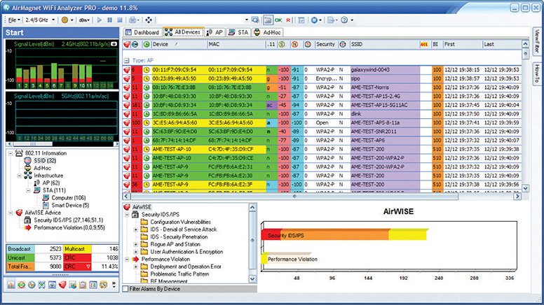
Figure 14-39 SNR on AirMagnet
Weird Connection
There are a number of situations where devices are connected to a wireless network and run at a good speed, but something is wrong—in some cases, dangerously wrong from a security perspective. Let’s look at a few of these situations.
Open Networks
Open (non-encrypted) 802.11 networks are the bane of users and administrators. The two biggest challenges are how to avoid unintentionally logging into an open network with an SSID identical to one you have in another location, and how to provide security in an open network environment.
It’s very common for your wireless device to access open networks with WAPs that use manufacturer default SSID names such as Linksys or D-Link. The danger with these is that bad guys know that most wireless devices, once they have created a profile to connect to one of these default, open SSIDs, will then automatically connect to them again should they ever see one—and bad guys love to use this as a tool to attack these devices.
The second issue with any open wireless is that all of the data is transferred in the clear. It’s easy for bad guys to listen in on your transmissions. The only way to avoid this is either to use a VPN or to use a Web browser add-on, like HTTPS Everywhere, that tries to connect you via HTTPS to every Web page.
Wrong SSID
It’s easy to access the wrong SSID. Some 802.11 clients are notorious for moving their list of discovered SSIDs in such a way that you think you are clicking one SSID when you are actually accidentally clicking the wrong one. The only fix to this is to practice diligence when logging onto a new SSID. For example, who hasn’t seen SSIDs such as the infamous “attwifi”? This SSID is AT&T’s attempt to use all of their clients as hotspots. Sadly, it’s a simple process to create an evil twin SSID (described in the upcoming section “Rogue Access Point”) to mimic the attwifi SSID and get otherwise unsuspecting people to log into it.
Manually entering an SSID can obviously result in a typo. Luckily, in these cases your typo won’t accidentally land you onto another SSID. You’ll just get an error.
Untested Updates/Incompatibilities
802.11 is an ever-evolving standard, and manufacturers learned a long time ago to work hard to ensure their devices could evolve with the standard. This means that anyone supporting any 802.11 network is going to find themselves continually updating client firmware/software and WAP firmware. These updates are almost always good, but you need to stay aware of problems.
First, always research and test any update (especially firmware updates as they aren’t too easy to reverse). Untested updates that go into your production network can potentially wreak havoc. If at all possible, run updates on a test network first.
Incompatibilities are related to untested updates in that they tend to appear at the same time an update appears. Make sure you are extremely clear on backward compatibility of different 802.11 versions. Also be aware that even in the same type of network there might be incompatibilities. A few years ago I bought what I thought was a dual-band (2.4- and 5.0-GHz) 802.11n WAP. I invested serious money in upgrading my 802.11n NICs in a few clients to accept dual band. Sadly, it wasn’t until I was installing the new WAP that I read in the instructions that the WAP only supported one of the two bands at a time, and was totally incompatible with my new, expensive wireless NICs. Ouch! Too bad I didn’t test the WAP before I tried to run it in my production environment.
Rogue Access Point
A rogue access point (rogue AP) is simply an unauthorized access point. Rogue access points have tortured every wireless network since the day Linksys came out with the first cheap wireless router back in the early 2000s. Most rogue APs aren’t evil: just a user wanting to connect to the network who installs a WAP in a handy location into the wired network. Evil rogue APs are far more nefarious, acting as a backdoor to a network or a man-in-the-middle attack, grabbing user names and passwords, among other items.
The most infamous form of rogue AP is called an evil twin. An evil twin is a rogue AP that intentionally mimics an existing SSID in order to get people to connect to it instead of the proper WAP. Evil twins work best in unsecured networks such as those you see in airports and hotels.
War Driving and War Chalking
We need to take a moment to discuss one of those weird CompTIA Network+ topics that covers very old issues that don’t really exist anymore: war driving and war chalking. A long time ago—as late as around 2005—there weren’t very many wireless networks around. Nerdy types would conduct war driving: looking for wireless networks by using omnidirectional antennas connected to laptops using wireless sniffing programs (this was well before every OS came with a client that located SSIDs). When a network was found, the war driver would place a special chalk mark on a nearby curb or sidewalk to tell other war drivers the location of the SSID. Figure 14-40 shows some of the more common war chalks.
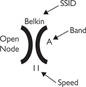
Figure 14-40 Sample war chalking mark with explanation
Chapter Review
Questions
1. Which wireless networking technology used the 5.0-GHz frequency range?
A. 802.11
B. 802.11a
C. 802.11b
D. 802.11g
2. Which technology enables use of a WAP without directly connecting the WAP to an AC power outlet?
A. AES
B. PoE
C. Powered Wi-Fi
D. TKIP
3. Which of the following is known as a Basic Service Set in infrastructure mode?
A. A WAP
B. A WPA
C. A RADIUS server
D. A TKIP
4. What feature enables 802.11n networks to minimize dead spots?
A. Channel bonding
B. FIFO
C. MIMO
D. Transit beamforming
5. Which of these consumer electronics may cause interference with 802.11n wireless networks?
A. Wireless telephones
B. Wireless televisions
C. Cellular telephones
D. Television remote controls
6. To achieve maximum Wi-Fi coverage in a room, where should you place the WAP?
A. Place the WAP on the north side of the room.
B. Place the WAP in the center of the room.
C. Place the WAP near a convenient electrical outlet.
D. It doesn’t matter where you place the WAP.
7. What hardware enables wireless PCs to connect to resources on a wired network segment in infrastructure mode? (Select two.)
A. An access point
B. A router
C. A hub
D. A wireless bridge
8. What do you call a wireless network in infrastructure mode with more than one access point?
A. BSS
B. EBSS
C. WBSS
D. ExNet
9. What type of server supports EAP-encrypted passwords in accordance with the 802.1X standard?
A. WAP server
B. WEP server
C. RADIUS server
D. NAS server
10. Which of the following is the most secure method of wireless encryption?
A. WEP
B. WEP2
C. WPA
D. WPA2
Answers
1. B. 802.11a operated in the 5.0-GHz frequency range.
2. B. Power over Ethernet enables a WAP to use electricity from a PoE switch rather than connect to an AC power outlet directly.
3. A. A single wireless access point (WAP) is a Basic Service Set. WPA is a data encryption scheme. A RADIUS server provides authentication via a user name and password. TKIP is used by the WPA encryption scheme to encrypt the data.
4. D. Transit beamforming enables an 802.11n WAP to minimize dead spots by using multiple antennas.
5. A. Many wireless telephones operate in the same 2.4-GHz frequency range as 802.11n wireless networking equipment and may cause interference.
6. B. To achieve maximum coverage, place the WAP in the center of the room.
7. A and D. A wireless access point or wireless bridge enables you to connect wireless PCs to a wired network segment.
8. B. A wireless network with more than one access point is called an EBSS, or Extended Basic Service Set.
9. C. A RADIUS server provides authentication through a user name and password encrypted with EAP.
10. D. WPA2 is the most secure because it uses CCMP-AES, a 128-bit cipher that is harder to crack than the 128-bit TKIP wrapper used by WPA. Both WPA and WPA2 are stronger than WEP. WEP2 was never fully developed.