Chapter Two
Media and Connectors
Introduction
To provide effective technical support, administrators must have a solid understanding of the logical standards and physical media used on today’s networks. Logical standards define characteristics such as the configuration of the network, the speed at which the network operates, and how devices access the network. Physical media refers to the cabling and connectors used to create the network.
Although you might think that knowledge of such things would be relevant only when designing or building a new network, you would be surprised at how frequently existing networks are expanded, upgraded, or reconfigured. When performing any of these tasks, your knowledge of standards and media will come into play. This is because the standards and media define and dictate such criteria as the maximum distance between devices, the capability of media to withstand outside interference, and even how much space is required in wiring closets and equipment cabinets.
We’ll begin our discussion by looking at some of the more common network media used on today’s networks.
Networking Media
As identified in Chapter 1, “Introduction to Networking,” a network is a group of connected computers. The computers on a traditional local area network (LAN) are connected by physical network media. Many types of media are used to connect network devices, and each type offers unique characteristics that you must understand to determine the media’s suitability for a given network environment.
Before discussing the various network media, this section identifies some of the terms and general considerations relevant to network media.
Note
Media Because not all networks use traditional cable, the term media is used. This term encompasses copper-based and fiber-optic cable as well as wireless media types.
Choosing the correct network media is an important consideration because the media forms the foundation for the entire network. When you’re working with any media, you must be aware of the factors that influence its suitability for a given network implementation. Some of the most common media considerations include interference, transmission speed, media length, and installation and repair. The following sections discuss each.
Media Interference
As a data signal travels through a specific media, it may be subjected to a type of interference known as electromagnetic interference (EMI). Common sources of EMI include computer monitors and fluorescent lighting fixtures—basically, anything that creates an electromagnetic field. If a network cable is too close to such devices, the signal within the cable can become corrupted. As you might expect, some network media are more susceptible than others to the effects of EMI. Copper-based media are prone to EMI and are managed using levels of shielding within the cable, whereas fiber-optic media using light transmissions do not suffer from EMI interference.
In most networks, standard cable provides sufficient resistance so that EMI isn’t a problem. However, you might work in some environments where such interference is a major concern. This is often the case when running cabling through ceilings, air ducts, or elevator shafts where interference is often present. In such instances, it becomes important to understand which media offer the greatest resistance to EMI and when EMIP resistant cabling should be used.
Note
EMI-resistant cable cost Cables designed for greater resistance to EMI cost more than those that aren’t.
EMI is just one of the threats to network transmissions. Data signals may also be subjected to something commonly referred to as cross talk, which occurs when signals from two cables or wires in close proximity to one another interfere with each other. As a result, the signals on both cables may become corrupted. When you’re troubleshooting intermittent network problems, it might be worth your time to confirm that cross talk or EMI is not at the root of your problems.
Data Transmission Rates
One of the more important media considerations is the supported data transmission rate or speed. Different media types are rated to certain maximum speeds, but whether they are used to this maximum depends on the networking standard being used and the network devices connected to the network.
Note
Bandwidth The transmission rate of media is sometimes referred to incorrectly as the bandwidth. In truth, the term bandwidth refers to the width of the range of electrical frequencies, or amount of channels that the media can support. Bandwidth correlates to the amount of data that can traverse the media at one time, but other factors determine what the maximum speed supported by a cable will be.
Transmission rates are normally measured by the number of data bits that can traverse the media in a single second. In the early days of data communications, this measurement was expressed as bits per second (bps), but today’s networks are measured in Mbps (megabits per second) and Gbps (gigabits per second).
Note
Also known as In your studies, you may see megabits per second and gigabits per second referred to as Mbit/s and Gbit/s. These are used interchangeably with Mbps and Gbps.
The different types of network media vary in the transmission rates they can accommodate. If you’re working on a network that accommodates huge amounts of data, transmission rates are a crucial consideration. In contrast, many older networks in small offices may only occasionally share files and maybe a printer. In such an environment, transmission rate is not a big issue.
Media Length
Not all networks have the same design. Some are isolated to a single office building, and others span large distances. For large network implementations, media length (that is, the maximum distance over which a certain type of media can be used) may be a factor in the network administrator’s choice of network media. Each media has a recommended maximum length, and surpassing these recommendations can cause intermittent network problems that are often difficult to troubleshoot.
All types of media have maximum lengths because a signal weakens as it travels farther from its point of origin. If the signal travels far enough, it can weaken so much that it becomes unusable. The weakening of data signals as they traverse the media is referred to as attenuation.
Copper-based media is particularly susceptible to attenuation, although different types of copper cable offer varying degrees of resistance to weakening signals. Some copper media, such as shielded twisted pair (STP), use a special shielding inside the cable, which helps protect the signal from outside interference. As a result, the distance a signal can travel increases.
Another strategy commonly employed to compensate for attenuation is signal regeneration. The cable itself does not perform the regeneration process; rather, network devices such as switches or repeaters handle signal regeneration. These devices strengthen the signal as it passes, and in doing so, they increase the distance the signal can travel. Network devices, such as hubs, routers, and switches, are covered in Chapter 3, “Networking Components and Devices.”
Exam Alert
Attenuation For the Network+ exam, you will be expected to know what attenuation is and how it affects a network.
Fiber-optic cable does not suffer from attenuation. Instead, it suffers from a condition called chromatic dispersion. Chromatic dispersion refers to the weakening of the light strength as it travels over distance. Although the scientific processes behind chromatic dispersion and attenuation are different, the end result is the same. Signals get weaker and at some point become unusable unless they are regenerated.
Some cable types, such as fiber optic, offer support for very long distances; other types, such as twisted pair, offer support for much shorter distances (a fraction of the distance of fiber). Some unbound media (wireless media) don’t have an exact figure for the allowable distance because so many variables can limit the effective range.
Installation and Repair
Some network media are easier to manage and install than others. This might seem like a minor consideration, but in real-world applications, it can be important. For example, fiber-optic cable is far more complex to install and troubleshoot than twisted pair. It’s so complicated, in fact, that special tools and training are often needed to install a fiber-optic based network. It is important to be aware of what you are in for when it’s time to implement or repair the network media.
Note
Plenum cables Plenum is the mysterious space that resides between the false, or drop, ceiling and the true ceiling. This space is typically used for the air conditioning or heating ducts. It might also hold a myriad of cables, including telephone, electrical, and network cables. The cables that occupy this space must be plenum rated. Plenum cables are coated with a nonflammable material, often Teflon or Kynar, and do not give off toxic fumes if they catch fire. As you might imagine, plenum-rated cables cost more than regular cables, but they are mandatory when cables are not run through a conduit. As an added bonus, plenum-rated cables suffer from less attenuation than nonplenum cables.
Simplex, Half-Duplex, and Full-Duplex
Those who do not know about duplexing might assume that network transmissions travel in any direction through the media. In fact, specific dialog control modes determine the direction in which data can flow through the network media. The three dialog modes are simplex, half-duplex, and full-duplex.
The simplex mode allows only one-way communication through the media. A good example of simplex is a car radio: There is only one transmitting device, and all other devices are receiving devices. A simplex dialog mode uses the full bandwidth of the media for transmitting the signal. The advantages of the simplex dialog mode can be seen in many applications, but networks are not among them.
Exam Alert
Simplex transmission A broadcast message—that is, one that is sent to all nodes on the network—is a good example of a simplex transmission. Remember this for the exam.
Half-duplex allows each device to both transmit and receive, but only one of these processes can occur at one time. Many networks are configured for and support only half-duplex communication. A good example of half-duplex transmission is a modem that can either transmit or receive, but not both simultaneously. The transmitting device can use the entire bandwidth of the media.
If at all possible, the preferred method of communication on networks is full-duplex mode. Full-duplex allows devices to receive and transmit simultaneously. On a network, devices that can use full-duplexing can double their transfer rates provided the devices they are connected to will also support the higher speed. For instance, a 100Mbps network card connected to a switch in full-duplex mode can operate at 200Mbps and therefore significantly increase the transmission speed. An example of full-duplex is a telephone conversation, where both parties are able to talk (send) and listen (receive) simultaneously.
Exam Alert
Know the difference Half-duplex allows two-way communication over a single channel. Full-duplex provides two-way communication by using different channels for sending and receiving signals. For the exam, know the difference.
Cable Media
Having now examined some of the general considerations that surround network media, the next step is to look at the different types of media commonly used on modern networks. Discussions of network media may not be the most glamorous part of computer networking, but they are important both for the Network+ exam and the real world.
Network media can be divided into two distinct categories: cable and wireless, sometimes referred to as bound and unbound media. Cable media come in three common types: twisted pair, coaxial, and fiber optic.
Even with the rapid growth of wireless networking, you will still spend much of your administrative time managing cable media. Cable media provide a physical connection between networked devices—for example, a copper cable running from a desktop computer to a hub or switch in the server room. Data transmissions pass through the cable to their destination.
The materials used to construct cable media include
• Metal (normally copper)—Copper-based cable is widely used to connect LANs and wide area networks (WANs).
• Glass or plastic—Optical cable, which uses glass or plastic, is mainly used for large-scale network implementations or over long distances.
The sections that follow review the various types of cable media and the networks on which they are used.
Twisted-Pair Cable
Now and for the foreseeable future, twisted-pair cable is the network media of choice. It is relatively inexpensive, easy to work with, and well suited to the needs of the modern network. There are two distinct types of twisted-pair cable: unshielded twisted pair (UTP) and shielded twisted pair (STP). UTP is by far the most common implementation of twisted-pair cable, and it is used for both telephone systems and computer networks.
Exam Alert
Another name for STP STP cable is sometimes called IBM-type cable. You should know this for the exam.
STP, as its name implies, adds extra shielding within the casing, so it copes with interference and attenuation better than regular UTP. Because of this shielding, cable distances for STP can be greater than for UTP; but, unfortunately, the additional shielding also makes STP more costly than regular UTP.
Note
What’s with the twist? Ever wonder why twisted-pair wiring is twisted? In the ongoing battle with interference and attenuation, it was discovered that twisting the wires within a cable resulted in greater signal integrity than running the wires parallel to one another. UTP cable is particularly susceptible to cross talk, and increasing the number of twists per foot in the wire achieves greater resistance against interference. The technique of twisting wires together is not limited to network cable; some internal and external SCSI cables employ a similar strategy.
Several categories of twisted-pair cabling exist, and the early categories are most commonly associated with voice transmissions. The categories are specified by the Electronics Industries Association/Telecommunications Industries Association (EIA/TIA). EIA/TIA is an organization that focuses on the development of standards for electronic components, electronic information, telecommunications, and Internet security. These standards are important to ensure uniformity of components and devices.
Note
MHz When talking about cabling, it is important to understand the distinction between Hertz and bits per second in relation to bandwidth. When we talk about bandwidth and a bits per second rating, we are referring to a rate of data transfer. For example, Category 2 cable has a 4Mbps rate of data transfer. When we refer to MHz and bandwidth, we are talking about the width range of frequency of the media. MHz refers to megahertz.
• Category 1—Voice-grade UTP telephone cable. Because of its susceptibility to interference and attenuation and its low bandwidth capability, Category 1 UTP is not practical for network applications.
• Category 2—Data-grade cable capable of transmitting data up to 4Mbps. Category 2 cable is too slow for networks. It is unlikely that you will encounter Category 2 used on any network today.
• Category 3—Data-grade cable capable of transmitting data up to 10Mbps with a possible bandwidth of 16MHz. Years ago, Category 3 was the cable of choice for twisted-pair networks. As network speeds pushed the 100Mbps speed limit, Category 3 became ineffective.
• Category 4—Data-grade cable that has potential data throughput of 16Mbps. Category 4 cable was often implemented in the IBM Token Ring networks. Category 4 cable is no longer used.
• Category 5—Data-grade was typically used with Fast Ethernet operating at 100Mbps with a transmission range of 100 meters. Although Category 5 was a popular media type, the cable is an outdated standard with newer implementations using the 5e standard. Category 5, despite being used primarily for 10/100 ethernet networking, can go faster. The IEEE 802.11ae standard specifies 1000Mbps over Category 5 cable. More on IEEE standards can be found in Chapter 6, “Ethernet Networking Standards.”
• Category 5e—Data-grade cable used on networks that run at 10/100 Mbps and even theoretically specifies 1000Mbps depending on the implementation. However, actual speeds would likely be a lot less. Category 5e cabling can be used up to 100 meters, depending on the network and standard used. Category 5e cable provides a minimum of 100MHz of bandwidth.
• Category 6—High-performance UTP cable capable of transmitting data up to 10Gbps. Category 6 has a minimum of 250MHz of bandwidth and specifies cable distances up to 100 meter cable length with 10/100/1000Mbps transfer, along with 10Gbps over shorter distances. Category 6 cable is typically made up of four twisted pairs of copper wire, but its capabilities far exceed those of other cable types. Category 6 twisted pair use a longitudinal separator, which separates each of the four pairs of wires from each other. This extra construction significantly reduces the amount of cross talk in the cable and allows for the faster transfer rates.
• Category 6a—Category 6a (augmented 6) offers improvements over Category 6 by offering a minimum of 500MHz of bandwidth. It specifies transmission distances up to 100 meters and used with 10Gbps networking standards such as 10Gbase-T.
Tip
Determining cable categories If you’re working on an existing network that is a few years old, you might need to determine which category of cable is used on the network. The easiest way to do this is simply to read the cable. The category number should be clearly printed on it.
Exam Alert
Cables don’t have speeds For the Network+ exam, be aware of the transfer rates at which commonly implemented network standards operate, rather than what the maximum speed supported by a cable might be. It is the networking equipment, manufactured to meet certain IEEE standards, that defines transfer rates of the network, not the network cabling. All the network cabling needs to do is support that speed as a minimum.
Sometimes when working with older networks, administrators encounter problems with out-of-date cabling. This sometimes occurs when a network is upgraded but some cable segments are not updated. In this scenario, you would need to select a plenum-rated cable to address the intermittent signal errors likely related to the fact the cable is run through the ceiling. Also, it is Category 3 cable, which would need to be upgraded to accommodate today’s network speeds. The specs should look like the following:
CMR riser plenum-rated cable
Meets or exceeds all CAT5e standards
Compliance to TIA/EEIA-568-B.2 and IEC /ISO 11801 standards
24 AWG solid bare copper cable
50 conductor
PVC polyvinyl chloride jacket
UL Listed E198134
Coaxial Cable
At one time, almost all networks used coaxial cable. Times have changed, and coax has fallen out of favor, giving way to faster and more durable cable options. That is not to say that you won’t be working with coax at some point. Many environments have been using coax and continue to do so because their network needs do not require an upgrade to another media—at least not yet. Many small offices continue to use coax on their networks, so we’ll include it in our discussion.
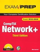
Coaxial cable resembles standard TV cable and is constructed using an outside insulation cover, braided metal shielding, and a copper wire at the center, as shown in Figure 2.1. The shielding and insulation help combat attenuation, cross talk, and EMI. Some coax is available with dual and even quad shielding.
Figure 2.1 Coaxial cable construction.
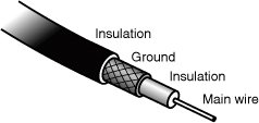
Two types of coax are used in networking: thin coax and thick coax. Neither is particularly popular anymore, but you are most likely to encounter thin coax.
Even though thin coax is by far the most widely used type of coax, you are unlikely to encounter it unless you are supporting an older network. As the name suggests, it is thin—at least compared to other forms of available coax. Thin coax, also called Thinnet, is only .25 inches in diameter, making it fairly easy to install. In networking uses, it has a maximum cable length of 185 meters (that is, just over 600 feet). If longer lengths of thin coax are used, data signals sent along the cable will suffer from attenuation, compromising data integrity. Table 2.1 summarizes the types of thin coax cable.
In network implementations, thin coax typically runs from computer to computer and uses Bayonet Neill Concelman (BNCs) to connect to network devices. Figure 2.2 shows BNC T connectors and terminators, which are often used with thin coax.
Figure 2.2 BNC T connectors and terminators.

Note
BNC connectors BNC connectors are also sometimes referred to as British Naval Connectors. Fortunately, CompTIA uses just the acronym, so you don’t need to worry about this for the Network+ exam.
Note
Cable and standards Thin coax cable is used for the Institute of Electrical and Electronics Engineers (IEEE) 10Base2 network standard.
Fiber-Optic Cable
Fiber-optic cable takes a step away from traditional copper-based media, and unlike standard networking cables, which use electrical signals to send data transmissions, fiber uses light. As a result, fiber-optic transmissions are not susceptible to EMI or cross talk, giving fiber cable an obvious advantage over copper-based media. In addition, fiber-optic cable is highly resistant to the signal weakening, referred to as chromatic dispersion, which was mentioned earlier in the section “Media Length.” All this allows data signals on a fiber-optic cable to travel distances measured in kilometers rather than meters, as with copper-based media. Further advantages of fiber-optic cable include the facts that it’s small in diameter, it’s lightweight, and it offers significantly faster transmission speeds than other cable media. Because of the construction of fiber cable and the fact that it uses light transmission rather than electronic signals, it is very resistant to signal tampering and eavesdropping making it more secure. Quite simply, fiber beats twisted-pair from almost every angle. Then why aren’t all networks using fiber cable? The same reason we don’t all drive Porsches: cost.
Several factors help ensure that we will continue to use twisted-pair and copper-based media in network environments. First, a fiber solution is costly in comparison to UTP-based cable implementations, eliminating it from many small- to mid-sized companies that simply do not have the budget to support a fiber-optic solution. The second drawback of fiber is that it can be more complex to install than UTP. Creating custom lengths of fiber-optic cable requires trained professionals and specialized tools. In contrast, custom lengths of UTP cabling can be created easily with commonly available tools. Third, fiber technology is incompatible with much of the existing electronic network infrastructure, meaning that to use fiber-optic cable, much of the current network hardware needs to be retrofitted or upgraded, and that can be a costly commitment.
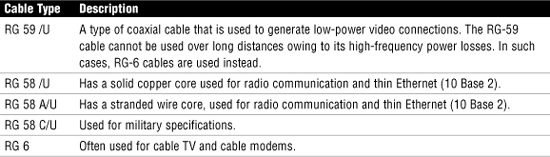
A fiber-optic cable consists of several components, including the optic core at the center, an optic cladding, insulation, and an outer jacket. The optic core is responsible for carrying the light signal and is commonly constructed of plastic or glass. Figure 2.3 shows an example of the components of a fiber-optic cable.
Two types of optical fiber are commonly available: single-mode and multimode. Multimode fiber (MMF) has a larger core than single-mode. This larger core allows hundreds of light rays to flow through the fiber simultaneously. Single-mode fiber (SMF), on the other hand, has a small core that allows only a single light beam to pass. The light transmissions in single-mode fiber pass through the core in a direct line, like a flashlight beam. The numerous light beams in multimode fiber bounce around inside the core, inching toward their destination. Because light beams bounce within the core, the light beams slow down, reduce in strength, and take some time to travel along the cable. For this reason, single-mode fiber’s speed and distance are superior to those of multimode.
Fiber cable can also have a variety of internal compositions (glass or plastic core), and the size of the core inside the cable, measured in microns, can vary. Some of the common types of fiber-optic cable include the following:
• 62.5 micron core/125 micron cladding multimode
• 50 micron core/125 micron cladding multimode
• 8.3 micron core/125 micron cladding single mode
Note
Fiber-optic cable transmission rates The rate at which fiber-optic cable can transmit data is determined by the mode used and whether the fiber core is glass or plastic.
Media Connectors
All forms of network media need to be physically attached to the networked devices in some way. Media connectors provide the interface between the cables and the devices to which they attach (similar to the way an electrical cord connects a television and an electrical outlet). This section explores the common connectors you are likely to encounter in your work and, perhaps more important, on the Network+ exam.
Exam Alert
Know the connectors You will be expected to identify the various media connectors and know which connectors are used with which cable.
RJ Connectors
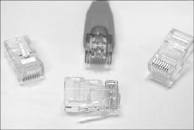
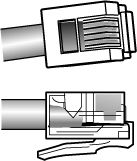
The connector you are most likely to encounter on modern networks is the RJ-45 (registered jack) connector. RJ-45 connectors bear a passing resemblance to the familiar RJ-11 connectors used with common telephone connections. The difference between the two connectors is that the RJ-11 connector supports six wires, whereas the RJ-45 network connector supports eight. Both RJ-11 and RJ-45 connectors are associated with twisted-pair cable. Figure 2.4 shows RJ-45 connectors, whereas Figure 2.5 shows RJ-11 connectors.
F-Type Connectors and RG-59/RG-6 Cables
F-Type connectors are used for attaching coaxial cable to devices. This includes RG-59 and RG-6 cables. In the world of modern networking, F-Type connectors are most commonly associated with connecting Internet modems to cable or satellite Internet providers’ equipment. However, they are also used for connecting to some proprietary peripherals.
Exam Alert
F is not for fiber Because of its name, people often mistakenly assume that an F-Type connector is used with fiber-optic cabling. It is not. The F-Type connector is used only with coaxial or copper-based cables, including RG-59 and RG-6 cables.
F-Type connectors screw into place, ensuring a firm contact between the cable and device. Hand tightening is all that should be required to make the contact, and the use of tools such as pliers to tighten connections is not recommended. Should a connector prove difficult to remove, however, you can use a pair of pliers or grips with a light pressure. F-Type connectors have a “nut” on the connection to assist this process. Figure 2.6 shows an example of an F-Type connector.
Figure 2.6 An F-Type connector.

RS-232 Standard
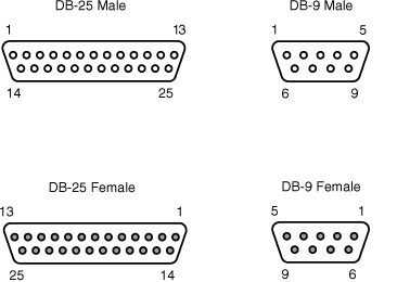
RS-232 (Recommended Standard-232) is a TIA/EIA standard for serial transmission between computers and peripheral devices such as modems, mice, and keyboards. The RS-232 standard was introduced in the 1960s and is still used today. However, today we have the third revision of the RS-232 standard appropriately named RS-232C. In most cases today, peripheral devices are more commonly connected using USB or wireless connections. In normal operation, RS-232 has a limit of about 50 feet with a data transfer rate of about 20kbps. RS-232 commonly uses a 25-pin DB-25 connector or a 9-pin DB-9 (AKA DE-9) connector. Figure 2.7 shows an example of RS-232 standard connectors.
Figure 2.7 RS-232 DB connectors.
Serial connectors need to attach to serial cables. Serial cables often use 4–6 wires to attach to the connectors and, similar to other cable types, can come in both an unshielded and shielded type. Shielding reduces interference and EMI for the cable. The distance a length of serial cable can run varies somewhat. This depends on the characteristics of the serial port and the quality of the serial cable. The RS-232 standard specifies serial cable distances up to 50 feet and a transfer speed up to 20kbps. Other serial standards increase this range and speed.
Fiber Connectors
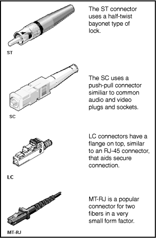
Several types of connectors are associated with fiber-optic cable. Which one is used is determined by the fiber implementation. Figure 2.8 shows some of the different fiber connectors you might encounter when working with fiber networks.
Figure 2.8 Fiber connectors. (Reproduced with permission from Computer Desktop Encyclopedia. 1981–2001. The Computer Language Co. Inc., www.computerlanguage.com.)
Exam Alert
Fiber-optic connectors For the Network+ exam, you will be expected to identify the various fiber-optic connectors. Specifically, the CompTIA Network+ exam objectives refer to the SC, ST, MT-RJ, and LC connectors.
IEEE 1394 (FireWire)
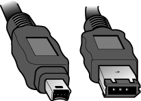
The IEEE 1394 interface, also known as FireWire, is more commonly associated with the attachment of peripheral devices such as digital cameras or printers than network connections. However, it is possible to create small networks with IEEE 1394 cables, which is why discussion of the connectors is included here.
The IEEE 1394 interface comes in a 4- or 6-pin version, both of which are shown in Figure 2.9.
Figure 2.9 4-pin (left) and 6-pin (right) IEEE 1394 (FireWire) connectors.
Universal Serial Bus (USB)
Universal Serial Bus (USB) ports are now a common sight on both desktop and laptop computer systems. Like IEEE 1394, USB is associated more with connecting consumer peripherals such as MP3 players and digital cameras than with networking. However, many manufacturers now make wireless network cards that plug directly into a USB port. Most desktop and laptop computers have between two and four USB ports, but USB hubs are available that provide additional ports if required.
A number of connectors are associated with USB ports, but the two most popular are Type A and Type B. Type A connectors are the more common of the two and are the type used on PCs. Although many peripheral devices also use a Type A connector, an increasing number now use a Type B. Figure 2.10 shows a Type A connector and a Type B connector.
Figure 2.10 Type A and Type B USB connectors.

Review Break
Cable Summary
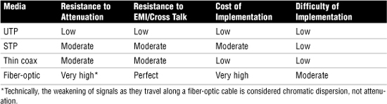
Be prepared: The CompTIA Network+ exam requires you to identify the basic characteristics of each cable type discussed in this section. In particular, you will be expected to know which cables offer the greatest resistance to interference and attenuation, and you must be able to identify which type of cable is best suited for a particular network environment. Table 2.2 summarizes the characteristics of the various cable media.
Table 2.2 Cable Media Characteristics
Wiring Standards and Specialized Cable
When it comes to working with networks, we need to understand how different cabling standards and ways of wiring network cable come into play. Some situations call for a specialized cable, such as networking two computers directly together. In this section we review some wiring standards and types of specialized cable.
568A and 568B Wiring Standards
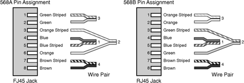
568A and 568B are telecommunications standards from the Telecommunications Industry Association (TIA) and the Electronics Industry Association (EIA). These 568 standards specify the pin arrangements for the RJ-45 connectors on UTP or STP cables. The number 568 references the order in which the wires within the Category 5 cable are terminated and attached to the connector.
The 568A and 568B standards are quite similar; the difference is the order in which the pins are terminated. The signal is the same for both, and both are used for patch cords in an ethernet network.
Network media may not always come with connectors attached, or you may need to make custom length cables. As a network administrator, this is when you need to know something about how these standards actually work. Before you can crimp on the connectors, you need to know which order the individual wires will be attached to the connector. Figure 2.11 shows the pin number assignments for the 568A and 568B standards. Pin numbers are read left to right with the connector tab facing down.
Figure 2.11 Pin assignments for the 568A and 568B standard.
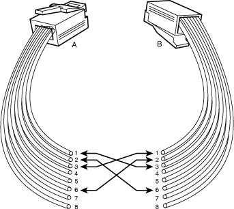
Straight Versus Crossover Cable
Two types of cables are used to connect devices to hubs and switches: crossover cables and straight-through cables. The difference between the two types is that in a crossover cable, two sets of wires are crossed; in a straight-through cable, all the wires run straight through.
Specifically, in a crossover cable, wires 1 and 3 and wires 2 and 6 are crossed: Wire 1 at one end becomes wire 3 at the other end, wire 2 at one end becomes wire 6 at the other end, and vice versa in both cases. You can see the differences between the two cables in Figure 2.12 and Figure 2.13. Figure 2.12 shows the pinouts for a straight-through cable, and Figure 2.13 shows the pinouts for a crossover cable.
Figure 2.12 Pinouts for a straight-through twisted-pair cable.
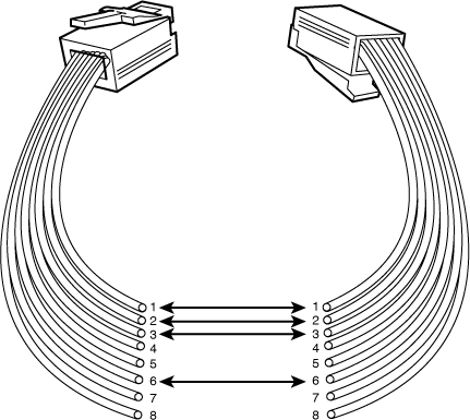
Figure 2.13 Pinouts for a crossover twisted-pair cable.
Note
Crossover function The crossover cable can be used to directly network two PCs together without using a hub or switch. This is done because the cable performs the function of switching. Using a straight-through cable and crossover cable to interconnect hubs and switches is covered in the next chapter.
To make a crossover ethernet cable, you will need to use both the 568A and 568B standards. One end of the cable can be wired according to the 568A standard and the other with the 568B standard.
Rollover and Loopback Cables
The rollover cable is a Cisco proprietary cable used to connect a computer system to a router or switch console port. The rollover cable resembles an ethernet UTP cable; however, it is not possible to use on anything but Cisco equipment. Like UTP cable, the rollover cable has eight wires inside and an RJ-45 connector on each end that connects to the router and the computer port.
As far as pinouts are concerned, pin 1 on one end of the rollover cable connects to pin 8 at the other end of the cable; similarly, pin 2 connects pin 7, and so on. The ends are simply reversed. After one end of the rollover cable is connected to the PC and the other to the Cisco terminal, the Cisco equipment can be accessed from the computer system using a program such as Hyper Terminal, which is included with Microsoft Windows products.
Exam Alert
Rollover For the Network+ exam, remember that the rollover cable is a proprietary cable used to connect a PC to a Cisco router.
A loopback cable, also known as a loopback plug, is a tool used to test and isolate network problems. If made correctly, the loopback plug causes the link light on a device such as a network interface card (NIC) to come on. This is a very quick and cheap way to test simple network cabling problems. The loopback plug redirects outgoing data signals back to the system. The system will then believe it is both sending and receiving data. The loopback plug is basically a troubleshooting tool used to test the device to see if it is sending and receiving properly. The loopback cable uses UTP cable and RJ-45 connectors.
Components of Wiring Distribution
So far in this chapter we have looked at various types of media and the associated connectors. In this final section we look at wiring in the closet, the place in networks where we connect the cables and networking devices. These rooms are often called the wiring closet or the telecommunications room. These telecommunication rooms contain the key network devices such as the hubs, routers, switches, servers, and the like.
In this telecommunications room the network media, such as patch cables, connect network devices to horizontal cables and the rest of the network. In this final section of the chapter, we look at some of the components found in the wiring closet, including cross connects, horizontal and vertical cabling, patch panels, and punchdown blocks. You also learn about two types of wiring closets and the importance of the demarcation point.
Network Cross Connects
The cable that runs throughout a network can be divided into two distinct sections: the horizontal cable that connects client systems to the network and vertical (backbone) cabling that runs between floors to connect different locations on the network. Both of these cable types have to be consolidated and distributed from a location; this location is a wiring closet.
In terms of cable distribution, there are three types: the horizontal cross connect, the intermediate cross connect, and the vertical or main cross connect. The term cross connect refers to the point where the cables running throughout the network meet and are connected. For example, the term horizontal cross connect refers to the distribution point for the horizontal cable.
The main or vertical cross connect is the location where outside cables enter the building for distribution. This may include Internet and phone cabling. The intermediate cross connect is typically used in larger networks and provides an intermediate cross connect between the main and horizontal cross connects. The horizontal cross connect is the location where the vertical and horizontal connections meet.
Horizontal Cabling
Within the telecommunications room, horizontal cabling connects the telecommunication room to the end user. Specifically, the horizontal cabling extends from the telecommunications outlet, or network outlet with RJ-45 connectors, at the client end, and includes all cable from that outlet to the telecommunication room to the horizontal cross connect. As mentioned, the term horizontal cross connect refers to the distribution point for the horizontal cable. The horizontal cross connect includes all connecting hardware, such as patch panels and patch cords. The horizontal cross connect is the termination point for all network horizontal cable. Figure 2.14 shows horizontal cabling.
Figure 2.14 Horizontal cabling.
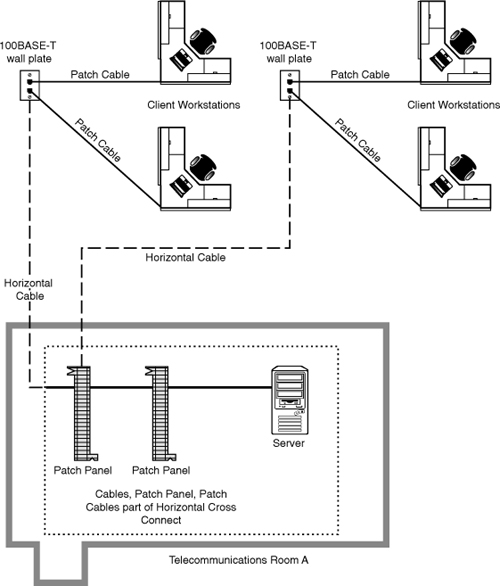
Horizontal cabling runs within walls and ceilings and is therefore referred to as permanent cable or structure cable. The length of cable running from the horizontal connects and the telecommunication outlet on the client side should not exceed 90 meters. Patch cables typically should not exceed 5 meters. This is because of the 100-meter segment restriction of twisted-pair cable.
Exam Alert
Horizontal wiring Horizontal wiring includes all cabling run from the wallplate or network connection to the telecommunications closet. The outlets, cable, and cross connects in the closet are all part of the horizontal wiring, which gets its name because the cable typically runs horizontally above ceilings or along the floor.
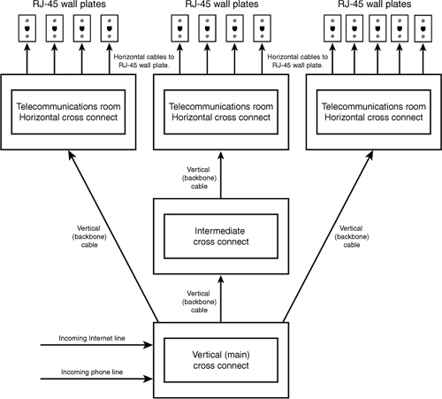
Vertical Cable
A vertical cable, or backbone cable, refers to the media used to connect telecommunication rooms, server rooms, and remote locations and offices. Vertical cable may be used to connect locations outside of the local LAN and requiring high-speed connections. Therefore, vertical cable is often fiber-optic cable or high-speed UTP cable. Figure 2.15 shows the relationship between horizontal cable and vertical cable.
Figure 2.15 Vertical and horizontal cabling.
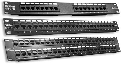
Patch Panels
If you ever looked in a telecommunications room, you have probably seen a distribution block, more commonly called a patch panel. A patch panel is a freestanding or wall-mounted unit with a number of RJ-45 port connections on the front. In a way, it looks like a wall-mounted hub without the light-emitting diodes (LEDs). The patch panel provides a connection point between network equipment such as hubs and switches and the ports to which PCs are connected, which are normally distributed throughout a building. Figure 2.16 shows three patch panels.
Figure 2.16 A selection of patch panels. (Photo courtesy of TRENDware International, www.trendware.com.)
Note
Direct cable connections Not all environments use patch panels. In some environments, cables are run directly between systems and a hub or switch. This is an acceptable method of connectivity, but it is not as easy to make tidy as a structured cabling system that uses a patch panel system and wall or floor sockets.
Type 66 and Type 110 Punchdown Blocks
Pre-dating the patch panel and still in use is the punchdown block. The wires from a telephony or UTP cable are attached to the punchdown block using a tool called a punchdown tool. Each punchdown block has a series of insulation displacement connectors (IDCs), which are metal tabs in which wires are placed. Because the connector strips the insulation on the wire, it is rather grandiose name. To use the punchdown tool, you place one wire at a time in the tip of the tool and push it into the connectors attached to the punchdown block. The wire insulation is stripped, and the wires are firmly embedded into the metal connector. Figure 2.17 shows an example of a typical punchdown tool and IDC connectors in a punchdown block.
Figure 2.17 Punchdown tool and connector block.
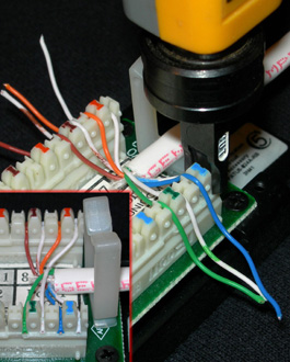
Using a punchdown tool is much faster than using wire strippers to prepare each individual wire and then twisting the wire around a connection pole or tightening a screw to hold the wire in place. In many environments, cable tasks are left to a specialized cable contractor. In others, the administrator is the one with the task of connecting wires to a patch panel.
The two main types of punchdown blocks used are type 66 and type 110. Type 66 is of older design and not as widely used as type 110. The 66 is a block used to connect wiring for telephone systems and other low-speed network systems. Like all punchdown blocks, a punchdown tool is used to force solid wire into metal slots on the 66 block.
The 66 block has 50 rows of IDC contacts to accommodate 25 pair. 66 block was primarily used for voice communication and although approved for Category 5, may not be suitable owing to cross talk problems. Also, although approved for Category 5 cable, it is limited to 16MHz.
For many years, the 66 block was standard in wiring closets and telecommunication rooms. Although the 66 block was used for low-speed data networks, it found its greatest use in voice applications. The 110 block replaced the 66 block for data communications because it supports higher frequencies and less cross talk. With its 50 rows of IDC connectors, the 66 block allowed for 25 pairs of wires to be connected. The 110 block uses different types of connections allowing for 25, 50, 100, 200, and 300 wire pairs.
A 110 block has two separate components: the 110-IDC connectors, which are used to terminate the wires, and the 110 wiring block, on which the connectors are attached. A 110 block consists of multiple 110 terminating connectors; there is a connector for each cable that must be terminated. The 110 block is typically mounted to the wall with each 110 connector visible from the front.
A 110 wiring block usually has several of rows of 110 terminating connectors attached. Individual wires are placed into a connector block using a punchdown tool. Similar to that of the 66 block, when the wires are punched into the IDC with the punchdown tool, the cable sheathing is pierced, and metal to metal contact occurs. Figure 2.17 shows a 110 punchdown tool placing wires in a 110 block.
Exam Alert
110 block The 110 block improves on the 66 block by supporting higher frequencies, less cross talk and therefore supporting higher-speed networks.
MDF and IDF
Main Distribution Frame (MDF) and Intermediate Distribution Frame (IDF) define types of wiring closets. The main wiring closet for a network typically holds the majority of the network gear, including routers, switches, wiring, servers, and so on. This is also typically the wiring closet where outside lines run into the network. This main wiring closet is known as the MDF. One of the key components in the MDF is a primary patch panel. The network connector jacks attached to this patch panel lead out to the building for network connections.
In some networks, multiple wiring closets are used. When this is the case, the MDF connects to these secondary wiring closets, or IDFs, using a backbone cable. This backbone cable may be UTP, fiber, or even coaxial. In today’s high speed networks, UTP Gigabit Ethernet or high-speed fiber are the media of choice. Figure 2.18 shows the relationship between the MDF and the IDF.
Figure 2.18 Relationship between MDFs and IDFs.

Demarcation Point
The demarcation point of a network refers to the connection point between the ISP’s part of the network and the customer’s portion of the network. This point is important for network administrators because it distinguishes the portion of the network the administrator is responsible for from the section the ISP is responsible for. As an example, for those who have high-speed Internet, the ISP will support everything from the cable modem back to their main distribution center. This is why, if a modem fails, it is replaced by the ISP and not by the customer. This is true for all connecting wiring to that point as well.
As mentioned previously, knowing the location of the demarcation point is essential because it marks the point where the customer (or administrator) is responsible should a problem occur, and who should pay for that problem. The ISP is responsible to ensure that the network is functional up to the demarcation point, and the customer/administrator is responsible to ensure everything from that point is operational.
The demarcation point is the point at which the ISP places its services in your network. There is not always a choice where this demarcation is placed. This means that a company may have six floors of offices and the demarcation point is in the basement and not practical for the network. This is when you need a demarcation extension, which extends the demarcation point to a more functional location. This may sound simple but it involves knowledge of cabling distances and other infrastructure-related requirements. The demarcation extension may be the responsibility of the administrator or for a fee, ISPs may provide them.
As you might imagine, we need some form of hardware at the demarcation point. This is the smart jack also known as the Network Interface Device (NID). The smart jack performs several primary functions, including:
• Loopback feature—The loopback feature is built in to the smart jack and, like the ethernet loopback cable, is used for testing purposes. In this case, the loopback feature allows for remote testing so technicians do not always need to be called to visit the local network to isolate problems.
• Signal amplification—The smart jack has the capability to amplify signals. This feature is similar to that of the function of repeaters in an ethernet network.
• Surge protection—Lighting and other environmental conditions can cause electrical surges that can quickly damage equipment. Many smart jacks include protection from environmental situations.
• Remote alarms—Smart jacks typically include an alarm that allows the owner to identify if something goes wrong with the smart jack and therefore the connections at the demarcation point.
Exam Alert
Demarc point DEMARC is the telephone company or ISP term for where their facilities or wires end and where yours begin.
Verify Wiring Installation and Termination
After a segment of network cable has been placed where it needs to go, whether run through the plenum or a connecting a patch cable, the final task is wiring termination. Termination refers to the process of connecting the network cable to the wall jack, plug, or patch panel. Termination is generally a straightforward process with little difficulty. You will be able to quickly test if the wiring and termination worked if the LED on the connected network card is lit. Also, if connecting a client system, you will be able to ping other devices on the network if all is working.
If you have run the wiring and completed termination and a system cannot access the network and the link light is not lit, there are few things to look for when troubleshooting the wiring installation and termination.
Verify termination and wiring installation link light on the device (switch/NIC) not lit:
• If connecting a patch cable to a PC or switch and no link light is lit, verify that the patch cable is good by switching it with a known working one.
• If it is a homemade patch cable, ensure that the RJ-45 connector is properly attached.
• Ensure that the RJ-45 connector is properly seated in the wall jack and NIC or switch port.
• If no link light is lit when connecting to a switch, change to another port on the switch. Sometimes a single port can be faulty.
• Verify that the correct patch cable is being used. It is possible that a rollover cable or crossover cable may be used accidentally.
• Verify that the cables used are the correct standard. For example, the patch cable is a 568A or 568B.
If the link light on a device is lit and intermittent problems occur
• Try replacing the cable with a known working one.
• Verify where the network cable is run. Ensure that a plenum-rated cable is used if it is running through ceilings or duct work.
• Look for heavy bends or partial breaks in the network cable.
• Verify that shielded cabling is being used in areas of potentially high interference.
• Check for the length of the cable run. Remember, the total run of cable should be about 100 meters. If the cable length exceeds this limit, you could experience intermittent signals errors that are hard to track down and troubleshoot.
Summary
Networks are often complex in design, maintenance, and implementation, and the basics—such as network standards, media, and connectors—are often forgotten. But these elements are the foundation blocks of a network.
Several types of cable are used on modern networks, including coaxial, twisted-pair, and fiber-optic cable. Each cable has different strengths and weaknesses, making some types of cable more suitable than others in a given network environment. Part of the role of the network administrator is to be able to identify the characteristics of the various cable types and to know how to troubleshoot them when required.
Each of these cable types requires the appropriate connector. By far the most commonly used connector type today is the RJ-45 connector, which is used with twisted-pair cable. Other connector types include SC and ST and LC connectors for fiber-optic cable and BNCs for thin coax cable.
To be able to add clients to an existing network, you need to identify the connectors and cables already in use on the network. By using observation techniques—examining the cables and connectors already in use—you can find out what you need to know to correctly add computers to the network.
Several key characteristics and considerations determine a media’s suitability for a specific network environment. These considerations include cross talk, attenuation, EMI, bandwidth, installation, and repair. You need to understand each of these to determine the appropriate media for a network.
Networks use dialog modes to determine the direction that transmissions flow over the network media. Three dialog modes are used: simplex, half-duplex, and full-duplex. Simplex allows only one-way communication; half-duplex allows two-way communication, but devices cannot send and receive simultaneously; and full-duplex allows devices to simultaneously receive and transmit.
There are important specialized cables used on networks that have different pin configurations, including rollover and crossover cables. The determination of pin configurations of straight-through cable are governed by the 568A and 568B standards.
Key Terms
• 568A
• 568B
• Coaxial
• Demarc
• EMI
• F-Type
• IDF
• LC
• Loopback
• MDF
• Media
• MMF
• MTRJ
• Plenum
• Rollover
• RJ-11
• RJ-45
• SC
• SMF
• ST
• STP
• Straight
• UTP
Apply Your Knowledge
Exercises
2.1 Identifying Cable Costs
In this project, you use the Internet to identify cable characteristics and associated costs.
In this chapter we looked at the network media, connectors, and standards—all of which are essential to networks. As a network administrator, you need to have a detailed knowledge of network media and their associated connectors. When you are called on to troubleshoot or implement a network, this knowledge will prove invaluable.
A common task for network administrators is to source out the costs of cable and connectors. Consider the following scenario: You have been contracted by BootCo, a maker of snowshoes and toques, to begin the process of implementing a network. BootCo requires a network of 25 systems and needs to know the costs associated with the media for the network. The network cable lengths are as follows:
6 cables × 22 meters each
10 cables × 18 meters each
4 cables × 9 meters each
5 cables × 72 meters each
In this exercise, you will determine the difference in cost of using Category 5e cable or Category 6 cable. You will also determine the cost difference in buying premade cables or making your own.
Estimated time: 20 minutes
1. Get on the Internet and from a search engine, look for a company that sells network cable. The search is likely to return many results, and it may be necessary to restrict your search to local vendors.
2. Browse a vendor’s website and locate UTP Category 5e and Category 6 cable.
3. You will need to price out the cables based on the previously stated lengths. Also remember that you will need 50 connectors, and a special tool called a “RJ-45 crimper” if you are going to make the cables yourself. The crimper is a special tool used to attach the RJ-45 connectors to the twisted-pair cable.
4. Continue to search the site for the costs for the Category 5e and Category 6 cable. To get a better idea of costs, it might be necessary to find information from several vendors.
5. Compare the cost of buying bulk cable and connectors to the cost of buying premade cables and connectors.
Exam Questions
1. Which of the following connectors are associated with the RS-232 standard? (Choose two.)
![]() A. DB-25
A. DB-25
![]() B. F-Type
B. F-Type
![]() C. DE-9
C. DE-9
![]() D. DB-45
D. DB-45
2. Which of the following statements are true of 568A and 568B wiring standards?
![]() A. 568 standards specify the pin arrangements for the RJ-45 connectors on coaxial cable and UTP cable.
A. 568 standards specify the pin arrangements for the RJ-45 connectors on coaxial cable and UTP cable.
![]() B. 568 standards specify the pin arrangements for the F-Type connectors on UTP or STP cables.
B. 568 standards specify the pin arrangements for the F-Type connectors on UTP or STP cables.
![]() C. 568 standards specify the pin arrangements for the RJ-45 connectors on UTP cable.
C. 568 standards specify the pin arrangements for the RJ-45 connectors on UTP cable.
![]() D. 568 standards specify the pin arrangements for fiber connectors.
D. 568 standards specify the pin arrangements for fiber connectors.
3. You are connecting some equipment at a client’s home. You notice that one of the cables provided with the equipment has an F-Type connector on it. Which of the following tasks are you most likely performing?
![]() A. Connecting a printer to a FireWire port.
A. Connecting a printer to a FireWire port.
![]() B. Creating a peer-to-peer network using IEEE1394 cables.
B. Creating a peer-to-peer network using IEEE1394 cables.
![]() C. Connecting a cable Internet modem.
C. Connecting a cable Internet modem.
![]() D. Creating a peer-to-peer network with STP cabling.
D. Creating a peer-to-peer network with STP cabling.
4. Which of the following copper-based media offers speeds up to 10Gbps and has a minimum of 250 MHz of bandwidth?
![]() A. Category 6b
A. Category 6b
![]() B. Single-mode fiber
B. Single-mode fiber
![]() C. Multimode fiber
C. Multimode fiber
![]() D. Category 6
D. Category 6
5. You are working on an older network and are required to add a client. The network is using Category 5 UTP cable. Which connector should you use?
![]() A. SC
A. SC
![]() B. ST
B. ST
![]() C. RJ-45
C. RJ-45
![]() D. RJ-11
D. RJ-11
6. Which of the following cable types are coated with a nonflammable material, often Teflon or Kynar, and do not give off toxic fumes if they catch fire?
![]() A. 1000BaseFX
A. 1000BaseFX
![]() B. Plenum grade
B. Plenum grade
![]() C. Nonplenum grade
C. Nonplenum grade
![]() D. Coaxial
D. Coaxial
7. While reviewing the specifications for a new network installation, you notice that the design calls for RJ-45 and SC connectors. The network is a high-speed design capable of supporting speeds up to 1000Mbps. What two types of network cable will the specifications call for?
![]() A. Thin coax and UTP
A. Thin coax and UTP
![]() B. RJ-11 and fiber optic
B. RJ-11 and fiber optic
![]() C. Cat 6 UTP and fiber optic
C. Cat 6 UTP and fiber optic
![]() D. Cat 5 UTP and fiber optic
D. Cat 5 UTP and fiber optic
8. Which of the following terms is used to describe interference created by individual wires within a network cable such as UTP?
![]() A. Attenuation
A. Attenuation
![]() B. Cross talk
B. Cross talk
![]() C. FDM
C. FDM
![]() D. Disruption
D. Disruption
9. Which of the following cable types are used to connect a computer system to a Cisco router or switch?
![]() A. Loopback
A. Loopback
![]() B. Loopunder
B. Loopunder
![]() C. Rollover
C. Rollover
![]() D. Rollback
D. Rollback
10. What is the maximum distance a signal can travel over multimode fiber?
![]() A. 10,000 meters
A. 10,000 meters
![]() B. 412 meters
B. 412 meters
![]() C. 500 meters
C. 500 meters
![]() D. 100 meters
D. 100 meters
11. Which of the following is used to redirect the outgoing signal back to the system to test a port or network card?
![]() A. Loopback cable
A. Loopback cable
![]() B. Rollover cable
B. Rollover cable
![]() C. UTP diagnostic cable
C. UTP diagnostic cable
![]() D. Interfeed cable
D. Interfeed cable
12. Which of the following media types offers the greatest resistance to interference?
![]() A. STP
A. STP
![]() B. Unshielded fiber
B. Unshielded fiber
![]() C. Fiber optic
C. Fiber optic
![]() D. UTP
D. UTP
13. What is the maximum transfer distance offered by RG-58 cable?
![]() A. 185 meters
A. 185 meters
![]() B. 275 meters
B. 275 meters
![]() C. 1,000 meters
C. 1,000 meters
![]() D. 550 meters
D. 550 meters
14. You are working in a wiring closet of a large corporation. The patch panel used has 50 rows of IDC contacts. Which type of patch panel is your company using?
![]() A. 100 punchblock
A. 100 punchblock
![]() B. 110 punchblock
B. 110 punchblock
![]() C. 66 punchblock
C. 66 punchblock
![]() D. 60 punchblock
D. 60 punchblock
15. Which of the following connectors is not associated with fiber-optic cabling?
![]() A. F-Type
A. F-Type
![]() B. SC
B. SC
![]() C. ST
C. ST
![]() D. LC
D. LC
16. Which of the following terms identifies the loss in signal strength as a signal travels through a media?
![]() A. Cross talk
A. Cross talk
![]() B. EMI
B. EMI
![]() C. Plenum
C. Plenum
![]() D. Attenuation
D. Attenuation
17. You are a running cable in a new network. You are running a series of cable from the wiring closet to the telecommunications port for the client systems. What type of cable are you running?
![]() A. Horizontal cable
A. Horizontal cable
![]() B. MDF cable
B. MDF cable
![]() C. Vertical cable
C. Vertical cable
![]() D. IDF cable
D. IDF cable
18. Which fiber-optic mode allows the fastest transfer rates?
![]() A. SC
A. SC
![]() B. ST
B. ST
![]() C. Single-mode
C. Single-mode
![]() D. Multimode
D. Multimode
19. A company that transfers sensitive data has asked you to install a media that is highly resistant to eavesdropping and signal tampering. Which of the following media would you recommend?
![]() A. STP
A. STP
![]() B. UTP
B. UTP
![]() C. FTP
C. FTP
![]() D. Fiber
D. Fiber
20. You need to network two client systems together but you do not have a switch or hub. Which of the following cable types could you use?
![]() A. Rollback
A. Rollback
![]() B. Loopback
B. Loopback
![]() C. Loop connector
C. Loop connector
![]() D. Crossover
D. Crossover
Answers to Exam Questions
1. A, C. RS-232 (Recommended Standard-232) is a TIA/EIA standard for serial transmission between computers and peripheral devices such as modems, mice, and keyboards. RS-232 commonly uses a 25-pin DB-25 connector or a 9-pin DE-9 connector. For more information, see the section “Media Connectors” in this chapter.
2. C. 568A and 568B are telecommunications standards from the Telecommunications Industry Association (TIA) and the Electronics Industry Association (EIA). These 568 standards specify the pin arrangements for the RJ-45 connectors on UTP or STP cables. For more information, see the section “568A and 568B Wiring Standards” in this chapter.
3. C. F-Type connectors are most commonly associated with the coaxial cable used to connect with cable Internet modems. F-Type connectors are not used on cables with IEEE 1394 or FireWire connectors, nor are they used with STP cabling. For more information, see the section “Media Connectors” in this chapter.
4. D. Category 6 high-performance UTP cable is rated and approved for 10GBASE-T networks. Category 6 has a minimum of 250MHz of bandwidth and specifies cable distances up to 100-meter cable length with 10/100/1000Mbps transfer, along with 10Gbps over shorter distances. For more information, see the section “Cable Media” in this chapter.
5. C. To add a client to an existing network that is using Category 5 UTP, you would work with RJ-45 connectors. SC and ST connectors are used with fiber-optic cable, and RJ-11 is the connector type associated with telephone cable. For more information, see the section “Media Connectors” in this chapter.
6. B. Plenum cables are coated with a nonflammable material, often Teflon or Kynar, and do not give off toxic fumes if they catch fire. Plenum-grade cables are typically run in floors and in walls. For more information, see the section “Networking Media” in this chapter.
7. C. RJ-45 connectors are associated with UTP cabling, whereas SC connectors are associated with fiber-optic cabling. Because the network design is high speed (1000Mbps), you would need to use Category 5e cabling or higher. All fiber-optic cable is capable of speeds in excess of 1000Mbps. For more information, see the section “Media Connectors” in this chapter.
8. B. The interference created between wires in a cable is called cross talk. Attenuation is the term given to the loss of strength in a signal as it travels over the media. Frequency Division Multiplexing (FDM) is a technology that allows more than one signal to be transmitted across a cable at one time. Disruption is not a term used to describe the interference created between wires in a cable. For more information, see the section “Networking Media” in this chapter.
9. C. The rollover cable is a Cisco proprietary cable used to connect a computer system to a router or switch console port. The rollover cable resembles an ethernet UTP cable; however, it is not possible to use on anything but Cisco equipment. Like UTP cable, the rollover cable has eight wires inside and an RJ-45 connector on each end that connect to the router and the computer port. For more information, see the section “Rollover and Loopback Cables” in this chapter.
10. B. The maximum distance for multimode fiber is 412 meters. Single-mode fiber increases the distance to 10,000 meters. Answers C and D are not valid. For more information, see the section “Networking Media” in this chapter.
11. A. A loopback cable is a tool used to test and isolate network problems. The loopback plug redirects outgoing data signals back to the system. The system then believes it is both sending and receiving data and the corresponding LEDs should light. For more information, see the section “Rollover and Loopback Cables” in this chapter.
12. C. Because fiber uses light to transmit data, it is not susceptible to EMI and cross talk. It is the media of choice in high-interference network environments. All the other cable types mentioned are copper based and are therefore susceptible, to varying degrees, to EMI and cross talk. It is not a type of network media. For more information, see the section “Cable Media” in this chapter.
13. A. RG-58, RG-59, and RG-6 are all types of thin coax. However, RG-58 is the standard associated with 10Base2 coaxial networks. In networking uses, it has a maximum cable length of 185 meters (that is, just over 600 feet). If longer lengths of thin coax are used, data signals sent along the cable will suffer from attenuation, compromising data integrity. For more information, see the section “Cable Media” in this chapter.
14. C. There are two main types of punchdown blocks used, type 66 and type 110. Type 66 is of older design and uses 50 rows of IDC contacts to accommodate 25-pair cable. Block 66 was primarily used for voice communication and, although approved for Category 5, may not be suitable owing to cross talk. 110 blocks are used for today’s networks and fully support the higher grade twisted-pair cable. For more information, see the section “Components of Wiring Distribution” in this chapter.
15. A. F-Type connectors are used with coaxial cabling. They are not used with fiber-optic cable. All the other connector types are used with fiber-optic cabling. For more information, see the section “Media Connectors” in this chapter.
16. D. Attenuation refers to signal degradation as it travels through media. Cross talk is the term used to refer to interference from other cables; EMI is a condition created by electronic or mechanical equipment. Plenum is not a type of interference; it is the term used to classify cables suitable for installation in suspended ceilings and other enclosed areas. For more information, see the section “Networking Media” in this chapter.
17. A. Within the telecommunications room, horizontal cabling connects the telecommunication room to the end user. The horizontal cabling extends from the telecommunications outlet, or network outlet with RJ-45 connectors, at the client end, and includes all cable from that outlet to the telecommunication room. A patch cord finishes the connection between the client system and telecommunication wall jack. For more information, see “Components of Wiring Distribution” in this chapter.
18. C. Single-mode fiber allows faster transfer rates than multimode fiber and supports longer data transmissions. SC and ST are types of fiber connectors, not types of cable. For more information, see the section “Cable Media” in this chapter.
19. D. Because of the construction of fiber cable and the fact that it uses light transmission rather than electronic signals, it is very resistant to tampering and eavesdropping. All the other cable types listed are copper based and are therefore less secure than fiber-based media. FTP is a protocol used for transferring files between systems on a network. It is not a type of network media. For more information, see the section “Fiber-Optic Cable” in this chapter.
20. D. The crossover cable can be used to directly network two PCs together without using a hub or switch. This is done because the cable performs the function of the switch. Using a straight-through cable and crossover cable to interconnect hubs and switches is covered in the next chapter. The section “Straight Versus Crossover Cable” briefly covered this topic in this chapter.