Part II. Final Review
Fast Facts: CompTIA Network+ Exam Prep, Third Edition
Network+
The fast facts listed in this chapter are designed as a refresher for some of the key knowledge areas required to pass the CompTIA Network+ certification exam. If you can spend an hour prior to your exam reading through this information, you will have a solid understanding of the key information required to succeed in each major area of the exam. You should be able to review the information presented here in less than an hour.
This summary cannot serve as a substitute for all the material supplied in this book. However, you should review these key points to refresh your memory on critical topics. In addition to the information in this chapter, remember to review the glossary terms because they are intentionally not covered here.
CompTIA uses the following domains, which are discussed in this book, to arrange the objectives for the Network+ exam:
• 1.0—Network Technologies
• 2.0—Network Media and Topologies
• 3.0—Network Devices
• 4.0—Network Management
• 5.0—Network Tools
• 6.0—Network Security
Network Technologies
For the CompTIA Network+ exam, 20% of the content will be focused on Domain 1, Network Technologies. This domain deals with the TCP/IP protocols suite, addressing, ports, routing, wireless, and more. Domain 1 is covered in Chapters 4, 5, and 7.
The TCP/IP Protocol Suite
Although TCP/IP is often referred to as a single protocol, the TCP/IP suite comprises many protocols. Each of the protocols in the TCP/IP suite provides a different function, and together they provide the functionality we know as TCP/IP.
Internet Protocol (IP)
• IP, which is defined in RFC 791, is the protocol used to transport data from one node on a network to another.
• IP is connectionless, which means that it doesn’t guarantee the delivery of data; it simply makes a best effort to do so. To ensure that transmissions sent via IP are completed, a higher-level protocol such as TCP is required.
• IP operates at the network layer of the OSI model. Refer to Chapter 9, “OSI Model,” for more on protocols and the OSI model.
Transmission Control Protocol (TCP)
• TCP, which is defined in RFC 793, is a connection-oriented protocol.
• Being connection-oriented means that TCP establishes a mutually acknowledged session between two hosts before communication takes place. TCP provides reliability to IP communications.
• TCP operates at the transport layer of the OSI model.
User Datagram Protocol (UDP)
• UDP, which is defined in RFC 768, is the brother of TCP. Like TCP, UDP uses IP as its transport protocol, but the big difference is that UDP does not guarantee delivery like TCP does. In a sense, UDP is a “fire and forget” protocol; it assumes that the data sent will reach its destination intact.
• UDP operates at the transport layer of the OSI model.
File Transfer Protocol (FTP)
• FTP is used for the uploading and downloading of files from a remote host running FTP server software.
• As well as uploading and downloading files, FTP allows you to view the contents of folders on an FTP server and rename and delete files and directories if you have the necessary permissions.
• FTP, which is defined in RFC 959, uses TCP as a transport protocol to guarantee delivery of packets.
• FTP is an application layer protocol.
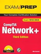
Table 1 Commonly Used FTP Commands
Secure File Transfer Protocol (SFTP)
• FTP transmits data between sender and receiver in an unencrypted format. The Secure File Transfer Protocol, which, based on the Secure Shell (SSH) technology, provides robust authentication between sender and receiver. It also provides encryption capabilities, which means that even if packets are copied from the network, their contents will remain hidden from prying eyes.
• SFTP is implemented through client and server software available for all commonly used computing platforms.
Trivial File Transfer Protocol (TFTP)
• A variation on FTP is TFTP, which is also a file transfer mechanism. However, TFTP does not have either the security capability or the level of functionality that FTP has.
• TFTP, which is defined in RFC 1350, is most often associated with simple downloads, such as those associated with transferring firmware to a device such as a router and booting diskless workstations.
• TFTP is an application layer protocol that uses UDP, which is a connectionless transport layer protocol. For this reason, TFTP is referred to as a connectionless file transfer method.
Simple Mail Transfer Protocol (SMTP)
• SMTP, which is defined in RFC 821, is a protocol that defines how mail messages are sent between hosts.
• SMTP uses TCP connections to guarantee error-free delivery of messages.
• SMTP can be used for both sending and receiving mail. POP and IMAP can be used only for receiving mail.
Hypertext Transfer Protocol (HTTP)
• HTTP, which is defined in RFC 2068, is the protocol that allows text, graphics, multimedia, and other material to be downloaded from an HTTP server.
• HTTP defines what actions can be requested by clients and how servers should answer those requests.
• HTTP is connection-oriented protocol that uses TCP as transport protocol.
Hypertext Transfer Protocol Secure (HTTPS)
• HTTPS uses a system known as Secure Sockets Layer (SSL), which encrypts the information sent between the client and the host.
• HTTPS is used online in such areas and banking and e-commerce to help ensure secure web communication.
Post Office Protocol Version 3/Internet Message Access Protocol Version 4 (POP3/IMAP4)
• POP3 and IMAP4 can be used to download, or pull, email from a server, but they cannot be used to send mail. That function is left to SMTP, which can both send and receive. POP3 and IMAP4 are both client/server models. POP3 downloads email messages from the server immediately when you check mail. IMAP4 leaves the messages on the server. IMAP4 and POP3 are application layer protocols.
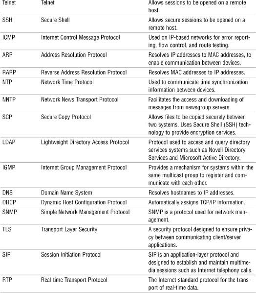
Telnet
• Telnet, which is defined in RFC 854, is a virtual terminal protocol. It allows sessions to be opened on a remote host, and then for commands to be executed on that remote host.
• One of the problems with Telnet is that it is not secure. As a result, remote session functionality is now almost always achieved by using alternatives such as Secure Shell (SSH).
• Telnet is often used to remotely access UNIX and Linux systems.
Secure Shell (SSH)
• SSH provides security by encrypting data as it travels between systems. This makes it difficult for hackers using packet sniffers and other traffic detection systems.
• SSH provides more robust authentication systems than Telnet.
• SSH is a more secure alternative to Telnet.
Internet Control Message Protocol (ICMP)
• ICMP, which is defined in RFC 792, is a protocol that works with the IP layer to provide error checking and reporting functionality.
• ICMP can be used for a number of functions. Its most common function is probably the widely used and incredibly useful ping utility.
Address Resolution Protocol (ARP)/Reverse Address Resolution Protocol (RARP)
• ARP, which is defined in RFC 826, is responsible for resolving IP addresses to Media Access Control (MAC) addresses.
• The Reverse Address Resolution Protocol (RARP) performs the same function as ARP, but in reverse. In other words, it resolves MAC addresses to IP addresses.
• RARP makes it possible for applications or systems to learn their own IP address from a router or DNS server. Such a resolution is useful for tasks such as performing reverse lookups in DNS. RARP is defined in RFC 903.
Network Time Protocol (NTP)
• NTP is the part of the TCP/IP protocol suite that facilitates the communication of time between systems.
Network News Transfer Protocol (NNTP)
• The Network News Transfer Protocol (NNTP) is a protocol associated with the posting and retrieval of messages from newsgroups.
• NNTP, which is defined in RFC977, is an application layer protocol that uses TCP as its transport mechanism.
Secure Copy Protocol (SCP)
• SCP provides a secure means to copy files between systems on a network.
• By using SSH technology, SCP encrypts data as it travels across the network, thereby securing it from eavesdropping.
Internet Group Management Protocol (IGMP)
• The IGMP protocol is used to register devices into a multicast group, as well as to discover what other devices on the network are members of the same multicast group.
• Common applications for multicasting include groups of routers on an internetwork and videoconferencing clients.
Domain Name System (DNS)
• DNS resolves hostnames and domain names, such as www.quepublishing.com, to IP addresses, such as 209.202.161.67.
• Like other TCP/IP-based services, DNS is a platform-independent protocol. Therefore, it can be used on Linux, UNIX, Windows, NetWare, and almost every other platform.
• In the days before the Internet, the network that was to become the Internet used a text file called HOSTS to perform name resolutions.
• Comments in a HOSTS file are preceded by a hash symbol (#).
• Domain names, along with any subdomains, are referred to as fully qualified domain names (FQDN) because they include all the components from the top of the DNS namespace to the host. For this reason, many people refer to DNS as resolving FQDNs to IP addresses.
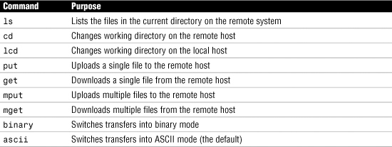
Table 2 Selected Top-Level Domains in the DNS Namespace
• Although the primary function of DNS is to resolve hostnames to IP addresses, it is also possible to have DNS perform an IP address-to-hostname resolution. This process is called reverse lookup.
Simple Network Management Protocol (SNMP)
• SNMP allows network devices to communicate information about their state to a central system. It also allows the central system to pass configuration parameters to the devices.
Dynamic Host Configuration Protocol (DHCP)
• The DHCP service automatically distributes IP information to client systems.
• When another system configured as a DHCP client is initialized, it asks the server for an address. If all things are as they should be, the server assigns an address from the scope to the client for a predetermined amount of time, known as the lease.
• DHCP is a protocol-dependent service, and it is not platform dependent. This means that you can use, for example, a Linux DHCP server for a network with Windows clients or a Novell DHCP server with Linux clients.
Transport Layer Security
• The Transport Layer Security (TLS) protocol is a security protocol designed to ensure privacy between communicating client/server applications.
• When a server and client communicate, TLS ensures that no one can eavesdrop and intercept or otherwise tamper with the data message. TLS is the successor to the SSL.
• TLS is composed of two layers: the first is the TLS Record Protocol and the second is the TLS Handshake Protocol. The TSL Record Protocol uses a reliable transport protocol such as TCP and ensures that the connection made between systems is private using data encryption. The TLS Handshake Protocol is used for authentication between the client and the server.
Session Initiation Protocol/Real-Time Transport Protocol
• SIP is an application-layer protocol designed to establish and maintain multimedia sessions such as Internet telephony calls.
• SIP can create communication sessions for such features as audio/videoconferencing, online gaming, and person-to-person conversations over the Internet.
• SIP uses TCP or UDP as transport protocols. Remember, TCP allows guaranteed delivery of data packets and UDP is a fire-and-forget transfer protocol.
• The Real-Time Transport Protocol (RTP) is the Internet-standard protocol for the transport of real-time data, including audio and video.
• RTP can use either TCP or UDP as a transport mechanism; however, UDP is most often used because applications using RTP are less sensitive to packet loss, but typically very sensitive to delays. UDP then is a faster protocol because packet delivery is not guaranteed.
TCP/IP Protocol Suite Summary
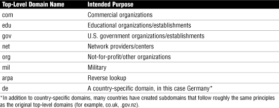
Table 3 TCP/IP Protocol Suite Summary
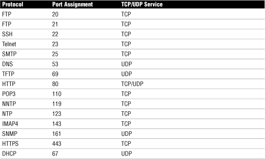
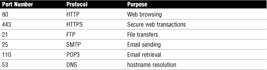
Identifying Common TCP/IP Port Numbers
TCP/IP has 65,535 ports available, but they are broken down into three designations:
• Well-known ports—The port numbers range from 0 to 1023. Be prepared to identify which ports are considered well known for the Network+ exam.
• Registered ports—The port numbers range from 1024 to 49151. Registered ports are used by applications or services that need to have consistent port assignments.
• Dynamic or private ports—The port numbers range from 49152 to 65535. These ports are not assigned to any protocol or service in particular and can be used for any service or application.
Table 4 Some of the Most Common TCP/IP Suite Protocols and Their Port Assignments
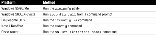
Identifying MAC Addresses
• A MAC address is sometimes referred to as a physical address because it is physically embedded in the interface.
• A MAC address is a 6-byte hexadecimal address that allows a NIC to be uniquely identified on the network.
• The MAC address forms the basis of network communication, regardless of the protocol used to achieve network connection.
• Because the MAC address is so fundamental to network communication, mechanisms are in place to ensure no possibility of duplicate addresses being used.
• A MAC address has two parts; consider: 00:D0:59:09:07:51. The first three bytes (00:D0:59) identify the manufacturer of the card; because only this manufacturer can use this address, it is known as the Organizational Unique Identifier (OUI). The last three bytes (09:07:51) are then referred to as the Universal LAN MAC address: They make this interface unique.
• Because MAC addresses are expressed in hexadecimal, only the numbers 0 through 9 and the letters A through F can be used in them. If you get a Network+ exam question about identifying a MAC address and some of the answers contain letters and numbers other than 0 through 9 and the letters A through F, you can discount those answers immediately.
Table 5 Methods of Viewing the MAC Addresses of NICs
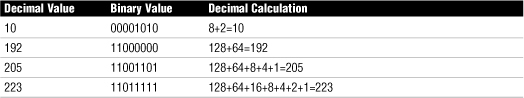
IPv4
• An IPv4 address is composed of four sets of 8 bits, or octets. The result is that IP addresses are 32 bits in length. Each bit in the octet is assigned a decimal value. The leftmost bit has a value of 128, followed by 64, 32, 16, 8, 4, 2, and 1, left to right.
• Each bit in the octet can be either a 1 or a 0. This numbering system is called binary. If the value is 1, it is counted as its decimal value, and if it is 0, it is ignored. If all the bits are 0, the value of the octet is 0. If all the bits in the octet are 1, the value is 255, which is 128+64+32+16+8+4+2+1.
Table 6 Examples of Numbers Derived Through Binary
Subnet Mask Assignment
• Like an IP address, a subnet mask is a 32-bit address expressed in dotted-decimal format. Unlike an IP address, though, a subnet mask performs just one function: It defines which parts of the IP address refer to the network address and which refer to the node address.
Classless Interdomain Routing (CIDR)
• Classless interdomain routing (CIDR) is a method of assigning addresses outside the standard Class A, B, and C structure. By specifying the number of bits in the subnet mask as a specific number, there is more flexibility than with the three standard class definitions.
• Using CIDR, addresses are assigned using a value known as the slash. The actual value of the slash depends on how many bits of the subnet mask are used to express the network portion of the address. For example, a subnet mask that uses all 8 bits from the first octet and 4 from the second would be described as /12, or “slash 12.” A subnet mask that uses all the bits from the first three octets would be called /24.
Default Gateways
• Default gateways are the means by which a device can access hosts on other networks for which it does not have a specifically configured route.
• Most workstation configurations default to just using default gateways rather than having any static routes configured. This allows workstations to communicate with other network segments, or with other networks, such as the Internet.
• In essence, the default gateway is simply the path out of the network for a given device.
IPv4 Address Classes
• IP addresses are grouped into logical divisions called classes. In the IPv4 address space are five address classes (A through E), although only three are used for assigning addresses to clients.
• Class D is reserved for multicast addressing, and Class E is reserved for future development.
Table 7 IPv4 Address Classes and the Number of Available Network/Host Addresses
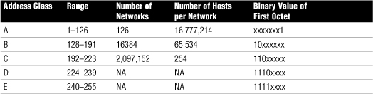
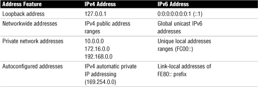
• The 127 network ID is reserved for the local loopback. The local loopback is a function that is built in to the TCP/IP protocol suite and can be used for troubleshooting purposes.
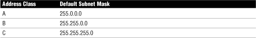
Subnet Masks
Table 8 Default Subnet Masks Associated with IP Address Classes
Understanding Subnetting
• Subnetting is a process by which bits from the node portion of an address are used to create more networks than you would have if you used the default subnet mask.
Table 9 Values of Subnets When Using 3 Bits from an Octet
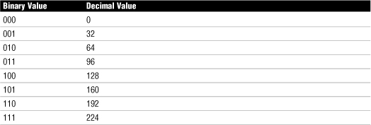
• Because no portion of the address can be all 0s or all 1s, you can’t use the 000 and 111 combinations. Therefore, you lose the network assignments of 0 and 224. You are conveniently left with six possible networks.
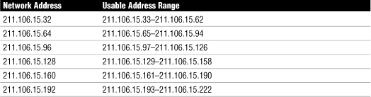
Table 10 Subnetted Network Possible Addresses from the Network 211.106.15.0
Private IP Address Schemes
Table 11 Private Address Ranges

IPv4 Address Types
The IPv4 has three primary types of address types, including unicast, broadcast, and multicast. It is important to be able to distinguish among these three types.
• Unicast—With unicast addresses, a single address is specified. Data sent with unicast addressing is delivered to a specific node identified by the address. It is a point-to-point address link.
• Broadcast—At the opposite end of the spectrum of unicast addressing is broadcast addresses. A broadcast address is an IP address that you can use to target all systems on a subnet or network instead of single hosts. In other words, a broadcast message goes to everyone on the network.
• Multicast—Multicasting is a mechanism by which groups of network devices can send and receive data between the members of the group at one time, instead of sending messages to each device in the group separately. The multicast grouping is established by each device being configured with the same multicast IP address.
Identifying IPv6 Addresses
• An IPv6 address example: 2001:0:4137:9e50:3cde:37d1:3f57:fe93
• An IPv6 address can be simplified by removing the leading zeros within each 16-bit block. All zeros cannot be removed, however, because each address block must have at least a single digit.
• Some of the IPv6 addresses you will work with have sequences of zeros. When this occurs the number is often abbreviated to make it easier to read. To further simplify the representation of IPv6 addresses, a contiguous sequence of 16-bit blocks set to 0 in the colon hexadecimal format can be compressed to “::”, known as double-colon.
• For example, the link-local address of 2001:0000:0000:0000:3cde:37d1:3f57:fe93 can be compressed to 2001::3cde:37d1:3f57:fe93.
• The process of removing zeros can be used only once in an IPv6 address. Using the double colons more than once would make it impossible to determine the number of 0 bits represented by each instance of “::”.
IPv6 Address Types
• Unicast IPv6 addresses—As you might have deduced from the name, a unicast address specifies a single interface. Data packets sent to a unicast destination travel from the sending host to the destination host. It is a direct line of communication.
• Multicast addresses—As with IPv4 addresses, multicasting sends and receives data between groups of nodes and sends IP messages to that group rather than to every node on the LAN (broadcast) or just one other node (unicast).
• Anycast addresses—Anycast addresses represent the middle ground between the unicast addresses and multicast addresses. Anycast delivers messages to any one node in the multicast group.
Additional Unicast Addresses
• Global unicast addresses—Global unicast addresses are the equivalent of IPv4 public addresses. These addresses are routable and travel throughout the network.
• Link-local address—Link-local addresses are those addresses designated for use on a single local network. Link-local addresses are automatically configured on all interfaces. This automatic configuration is equivalent to the 169.254.0.0/16 automatically assigned IPv4 addressing. The prefix used for a link-local address is fe80::/10.
• Unique local addresses—Unique local addresses are equivalent to the IPv4 private address space (10.0.0.0/8, 172.16.0.0/12, and 192.168.0.0/16). Like IPv4, where private address ranges are used in private networks, IPv6 uses site-local addresses that will not interfere with global unicast addresses. The prefix used for the site-local address is (Fc00::/7).
• Stateless refers to IP autoconfiguration, where administrators need not manually input configuration information. In a stateful configuration, network devices obtain address information from a server.
• With IPv4, an address (127.0.0.1) is reserved as the loopback address. IPv6 has the same reservation. IPv6 address 0:0:0:0:0:0:0:1 is reserved as the loopback address.
Table 12 Comparing IPv4 and IPv6
Static Addressing
• Static addressing refers to the manual assignment of IP addresses to a system. In other words, a person has to physically configure the system with the correct IP address.
• Some systems, such as web servers, should always be configured with static IP addresses.
Dynamic Addressing
• Dynamic addressing refers to the assignment of IP addresses automatically.
• On modern networks the mechanism used to do this is the Dynamic Host Configuration Protocol (DHCP).
• DHCP is a protocol, part of the TCP/IP protocol suite, that allows a central system to provide client systems with IP addresses.
• Assigning addresses automatically with DHCP alleviates the burden of address configuration and reconfiguration that occurs with static IP addressing.
APIPA and IPv4
• The function of APIPA is to allow a system to provide itself with an IP address in the event that it is unable to receive an address dynamically from a DHCP server.
• APIPA assigns the system an address from the 169.254.0.0 address range and configures an appropriate subnet mask (255.255.0.0).
• APIPA cannot configure the system with a default gateway address. As a result, communication is limited to the local network.
• If a system that does not support APIPA cannot get an address from a DHCP server, the default action is to configure itself with an IP address of 0.0.0.0. Keep this in mind when troubleshooting IP addressing problems on non-APIPA platforms.
Routing Protocols
• With static routing, network route information must be manually entered by the administrator into a routing table. There are two main disadvantages of this approach: First, manually entering routes is time consuming and susceptible to human error. Second, if the topology of the network changes, the routers must be manually reconfigured.
• Dynamic routing uses routing protocols that are designed to dynamically discover paths to network destinations.
Distance-Vector Protocols
• With distance-vector routing protocols, each router communicates all the routes it knows about to all other routers to which it is directly attached (that is, its neighbors).
• With distance-vector protocols, each router in the network knows only about the routers to which it is attached. It doesn’t know how to complete the entire journey; instead, it only knows how to make the next hop.
• Hops are the means by which distance-vector routing protocols determine the shortest way to reach a given destination. Each router constitutes one hop; so if a router is four hops away from another router, three routers, or hops, are between the router and its destination.
• Several distance-vector protocols in use today include Routing Information Protocol (RIP and RIPv2), Enhanced Interior Gateway Routing Protocol (EIGRP), and the Border Gateway Protocol (BGP).
Link-State Protocols
• A router that uses a link-state protocol differs from a router that uses a distance-vector protocol because it builds a map of the entire network and then holds that map in memory.
• On a network that uses a link-state protocol, routers send out link-state advertisements (LSAs) that contain information about what networks they are connected to. The LSAs are sent to every router on the network, thus enabling the routers to build their network maps.
• Link-state protocols include the Open Shortest Path First (OSPF) and the intermediate system to intermediate system (IS-IS).
NAT, PAT, SNAT
• Using NAT means that only one registered IP address is needed on the external interface of the system acting as the gateway between the internal and external networks.
• NAT allows administrators to conserve public IP addresses and at the same time secure the internal network.
• Port Address Translation (PAT) is a variation on NAT. With PAT, all systems on the LAN are translated to the same IP address, but with a different port number assignment.
• Static NAT is a simple form of NAT. SNAT maps a private IP address directly to a static unchanging public IP address. This allows an internal system, such as a mail server, to have an unregistered (private) IP address and still be reachable over the Internet.
Wireless Radio Channels
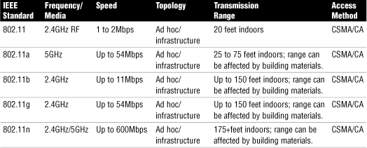
• A channel is the band of RF used for the wireless communication. Each IEEE wireless standard specifies the channels that can be used.
• The 802.11a standard specifies radio frequency ranges between 5.15 and 5.825GHz. In contrast, 802.11b and 802.11g standards operate between the 2.4 to 2.483GHz range.
• It is recommended that the nonoverlapping channels be used for communication. In the U.S., 802.11b/g use 11 channels for data communication as mentioned; three of these—channels 1, 6, and 11—are nonoverlapping channels.
• When troubleshooting a wireless problem in Windows, use the ipconfig command to see the status of IP configuration. Similarly, use the ifconfig command in Linux.
Wireless Interference Types
• Physical objects—Trees, masonry, buildings, and other physical structures are some of the most common sources of interference. The density of the materials used in a building’s construction determines the number of walls the RF signal can pass through and still maintain adequate coverage. Concrete and steel walls are particularly difficult for a signal to pass through.
• Radio frequency interference—Wireless technologies such as 802.11b/g use an RF range of 2.4GHz, and so do many other devices, such as cordless phones, microwaves. Devices that share the channel can cause noise and weaken the signals.
• Electrical interference—Electrical interference comes from devices such as computers, refrigerators, fans, lighting fixtures, or any other motorized devices. The impact that electrical interference has on the signal depends on the proximity of the electrical device to the wireless access point.
• Environmental factors—Weather conditions can have a huge impact on wireless signal integrity. Lightning, for example, can cause electrical interference, and fog can weaken signals as they pass through.
802.11 Wireless Standards
Table 13 802.11 Wireless Standards
Wired Equivalent Privacy (WEP)
• WEP is an IEEE standard introduced in 1997 designed for securing 802.11 wireless networks.
• WEP originally used a 40-bit number key, but later specified 128-bit encryption.
Wi-Fi Protected Access (WPA)
WPA was designed to improve on the security weaknesses of WEP and to be backward compatible with older devices using the WEP standard.
WPA addressed two main security concerns:
• Enhanced data encryption—WPA uses a temporal key integrity protocol (TKIP), which scrambles encryption keys using a hashing algorithm. Then the keys are issued an integrity check to verify that they have not been modified or tampered with during transit.
• Authentication—WPA uses the authentication protocol EAP to increase security.
802.1X
• 802.1X is an IEEE standard specifying port-based network access control.
• 802.1X was not specifically designed for wireless networks; rather, it provides authenticated access for both wired and wireless networks.
• Port-based network access control uses the physical characteristics of a switched local area network (LAN) infrastructure to authenticate devices attached to a LAN port and to prevent access to that port in cases where the authentication process fails.
RADIUS
• RADIUS is a protocol that allows a single server to become responsible for all remote access authentication, authorization, and auditing (or accounting) services.
• The remote user dials in to the remote access server, which acts as a RADIUS client, or network access server (NAS), and connects to a RADIUS server.
• The RADIUS server performs authentication, authorization, and auditing (or accounting) functions and returns the information to the RADIUS client (which is a remote access server running RADIUS client software); the connection is either established or rejected based on the information received.
Temporal Key Integrity Protocol
• The temporal key integrity protocol (TKIP) was designed to address the shortcomings of the WEP security protocol.
• WPA wireless security uses TKIP.
• TKIP is an encryption protocol defined in IEEE 802.11i. TKIP was not only designed to increase security but also to use existing hardware, making it easy to upgrade to TKIP encryption.
Network Media and Topologies
For the CompTIA Network+ exam, 20% of the content will be focused on Domain 2, Network Media and Topologies. This domain deals with the structure of the network including topologies and the media used to create networks. Domain 2 is covered in Chapters 1, 2, 6, and 8.
Network Types and Physical and Logical Topologies
The following are some of the important aspects of network types:
• There are two types of computer networks:
• Peer-to-peer networks—Peer-to-peer networks are useful for only relatively small networks. They are often used in small offices or home environments.
• Client/server networks—Client/server networks, also called server-centric networks, have clients and servers. Servers provide centralized administration, data storage, and security. The client system requests data from the server and displays the data to the end user.
Following are some of the important aspects of network topologies:
• Network topologies can be defined on a physical level or on a logical level.
• The bus network topology is also known as a linear bus because the computers in such a network are linked together using a single cable called a trunk, or backbone. The following are important features of the bus topology:
• The computers can be connected to the backbone by a cable, known as a drop cable, or, more commonly, directly to the backbone via T connectors.
• At each end of the cable, terminators prevent the signal from bouncing back down the cable.
• If a terminator is loose, data communications may be disrupted. Any other break in the cable will cause the entire network to fail.
Table 14 Bus Topology: Features, Advantages, and Disadvantages

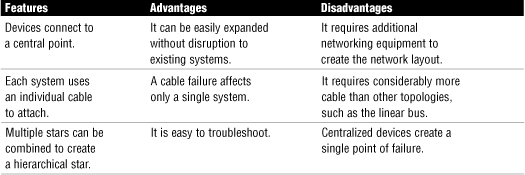
• In a star topology, each device on the network connects to a centralized device via a single cable. The following are important features of the star topology:
• Computers in a star network can be connected and disconnected from the network without affecting any other systems.
• In a star configuration, all devices on the network connect to a central device, and this central device creates a single point of failure on the network.
• The most common implementation of the physical star topology is the Ethernet 100BaseT standard.
Table 15 Star Topology: Features, Advantages, and Disadvantages
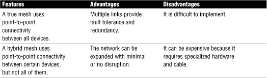
• The wired mesh topology requires each computer on the network to be individually connected to each other device. This configuration provides maximum reliability and redundancy for the network.
Table 16 Mesh Topology: Features, Advantages, and Disadvantages
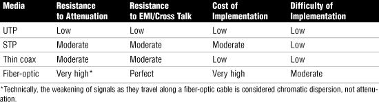
Media Considerations
• EMI is caused by electromagnetic interference.
• Many things cause EMI; common sources include computer monitors and fluorescent lighting fixtures—basically, anything that creates an electromagnetic field. If a network cable is too close to such devices, the signal within the cable can become corrupted.
• Cross talk occurs when signals from two cables in close proximity to one another interfere with each other. As a result, the signals on both cables may become corrupted.
• All media has a maximum length because a signal weakens as it travels farther from its point of origin. If the signal travels far enough, it can weaken so much that it becomes unusable. The weakening of data signals as they traverse the media is referred to as attenuation.
• Copper-based media is susceptible to attenuation, although different types of cable offer varying degrees of resistance to weakening signals.
• Some media, such as shielded twisted pair (STP), use a special shielding inside the cable, which increases the distance the signal travels. Another strategy commonly employed to compensate for attenuation is signal regeneration.
• Fiber-optic cable does not suffer from attenuation. Instead, it suffers from a condition called chromatic dispersion. Chromatic dispersion refers to the weakening of the light strength as it travels over distance.
Simplex, Half-Duplex, and Full-Duplex
• The simplex mode allows only one-way communication through the media.
• Half-duplex allows each device to both transmit and receive, but only one of these processes can occur at one time.
• Full-duplex allows devices to receive and transmit simultaneously.
Twisted-Pair
The Electronic Industries Association/Telecommunications Industry Association (EIA/TIA) has specified a number of categories of twisted-pair cable:
• Category 1—Voice-grade UTP telephone cable. Because of its susceptibility to interference and attenuation and its low bandwidth capability, Category 1 UTP is not practical for network applications.
• Category 2—Data-grade cable capable of transmitting data up to 4Mbps. Category 2 cable is too slow for networks. It is unlikely that you will encounter Category 2 used on any network today.
• Category 3—Data-grade cable capable of transmitting data up to 10Mbps with a possible bandwidth of 16MHz. Years ago Category 3 was the cable of choice for twisted-pair networks. As network speeds pushed the 100Mbps speed limit, Category 3 became ineffective.
• Category 4—Data-grade cable that has potential data throughput of 16Mbps. Category 4 cable was often implemented in the IBM Token Ring networks. Category 4 cable is no longer used.
• Category 5—Data-grade was typically used with Fast Ethernet operating at 100Mbps with a transmission range of 100 meters. Although Category 5 was a popular media type, the cable is outdated with newer network implementations switching to category 5e twisted pair. Category 5 provides a minimum of 100MHz of bandwidth. Category 5, despite being used primarily for 10/100 ethernet networking, can go faster. The IEEE 802.11ae standard specifies 1000Mbps over Category 5 cable. More on IEEE standards can be found in Chapter 6.
• Category 5e—Data-grade cable used on networks that run at 10/100Mbps and even up to 1000Mbps. Category 5e cabling can be used up to 100 meters, depending on the implementation and standard used. Category 5e cable provides a minimum of 100MHz of bandwidth.
• Category 6—High-performance UTP cable capable of transmitting data up to 10Gbps. Category 6 has a minimum of 250MHz of bandwidth and specifies cable distances up to 100 meter cable length with 10/100/1000Mbps transfer, along with 10Gbps over shorter distances.
• Category 6a—Category 6a (augmented 6) offers improvements over Category 6 by offering a minimum of 500MHz of bandwidth. It specifies transmission distances up to 100m with 10Gbps networking speeds.
Coaxial Cable
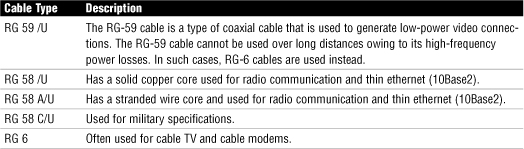
Fiber-Optic Cable
• Two types of optical fiber are commonly available: single-mode and multimode.
• Multimode fiber (MMF) has a larger core than single-mode. This larger core allows hundreds of light rays to flow through the fiber simultaneously.
• Single-mode fiber (SMF), on the other hand, has a small core that allows only a single light beam to pass. The light transmissions in single-mode fiber pass through the core in a direct line, like a flashlight beam.
• Because of its direct single beam of light, SMF allows for longer distances.
Media Connectors
• SC, ST, LC, and MT-RJ connectors are associated with fiber cabling.
• ST connectors offer a twist-type attachment, and SC and LC are push-on connectors. MT-RJ is somewhat similar in appearance to an RJ-45 connector but is longer. MT-RJ connectors have a flange, like an RJ-45 connector, to secure the cable in place.
• RJ-45 connectors are used with the 8-wire UTP cable used in network implementations. RJ-11 connectors are used with the 4-wire UTP cable associated with telephone systems.
• F-Type connectors are used with coaxial cable. In network implementations, they are most commonly associated with connecting cable modems to incoming cable connections.
• IEEE 1394 (FireWire) can use either a 4-pin or a 6-pin connector.
RS-232 Standard
• RS-232 (Recommended Standard-232) is a TIA/EIA standard for serial transmission between computers and peripheral devices such as modems, mice, and keyboards.
• In normal operation, RS-232 has a limit of about 50 feet with a data transfer rate of about 20Kbps. RS-232 commonly uses a 25 pin DB-25 connector or a 9 pin DB-9 or DE-9 connector.
Table 18 Cable Media Characteristics
568A and 568B Wiring Standards
• 568A and 568B are telecommunications standards from the Telecommunications Industry Association (TIA) and the Electronics Industry Association (EIA). These 568 standards specify the pin arrangements for the RJ-45 connectors on UTP or STP cables.
• The 568A and 568B standards are quite similar; the difference is the order in which the pins are terminated.
Straight Versus Crossover Cable
• Two types of cables are used to connect devices to hubs and switches: crossover cables and straight-through cables.
• The difference between the two types is that in a crossover cable, two of the wires are crossed; in a straight-through cable, all the wires run straight through.
• The crossover cable can be used to directly network two PCs without using a hub or switch. This is done because the cable performs the function of the switch.
• To make a crossover ethernet cable, you need to use both the 568A and 568B standards. One end of the cable can be wired according to the 568A standard and the other with the 568B standard.
Rollover and Loopback Cables
• The rollover cable is a Cisco proprietary cable used to connect a computer system to a router or switch console port.
• A loopback cable, also known as plug, is a tool used to test and isolate network problems. If made correctly, the loopback plug will cause the link light on a device such as a network card (NIC) to come on.
Horizontal Cable and Cross Connect
• Within the telecommunications room, horizontal cabling connects the telecommunication room to the end user.
• The horizontal cabling extends from the telecommunications outlet, or network outlet with RJ-45 connectors, at the client end; it includes all cable from that outlet to the telecommunication room to the horizontal cross connect.
• The term horizontal cross connect refers to the distribution point for the horizontal cable. The horizontal cross connect includes all connecting hardware such as patch panels and patch cords. The horizontal cross connect is the termination point for all network horizontal cable.
• The length of cable running from the horizontal connects and the telecommunication outlet on the client side should not exceed 90 meters. Patch cables used typically should not exceed 5 meters.
Vertical Cable and Cross Connect
• Vertical cable, or backbone cable, refers to the media used to connect telecommunication rooms, server rooms, and remote locations and offices.
• Vertical cable may be used to connect locations outside of the local LAN and require high-speed connections. Therefore, vertical cable is often fiber-optic cable or high-speed UTP cable.
Patch Panels
• A patch panel is a freestanding or wall-mounted unit with a number of RJ-45 port connections on the front.
• The patch panel provides a connection point between network equipment such as hubs and switches and the ports to which PCs are connected, which are normally distributed throughout a building.
Type 66 and Type 110 Punchdown Blocks
• There are two main types of punchdown blocks used, type 66 and type 110. Type 66 is of older design and not as widely used as type 110. The 66 is a block used to connect wiring for telephone systems and other low-speed network systems.
• A punchdown tool is used to force solid wire into metal slots on the 66 block.
• The 66 block has 50 rows of IDC contacts to accommodate 25-pair cable.
• The 110 block improves on the 66 block by supporting higher frequencies; it has less cross talk and therefore supports higher speed networks.
MDF and IDF
• Main Distribution Frame (MDF) and Intermediate Distribution Frame (IDF) define types of wiring closets. The main wiring closet for a network typically holds the majority of the network gear, including routers, switches, wiring, servers, and so on.
• In some networks, multiple wiring closets are used. When this is the case, the MDF connects to these secondary wiring closets, or IDFs, using a backbone cable. This backbone cable may be UTP, fiber, or even coaxial.
Demark, Demark Extension
• The demarcation point of a network refers to the connection point between the ISP’s part of the network and the customer’s portion of the network.
• The point is important for network administrators because it distinguishes the portion of the network the administrator is responsible for from the section the ISP is responsible for.
• The demarc extension takes the installation of the ISP equipment to a more functional location.
Ethernet Standards
The following tables outline the characteristics of various 802.3 ethernet standards.
Table 19 summarizes the characteristics of the 802.3u Fast Ethernet specifications.
Table 19 Summary of 802.3u Fast Ethernet Characteristics
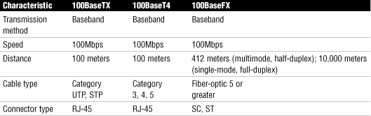
Table 20 Summary of IEEE 802.3z Gigabit Ethernet Characteristics
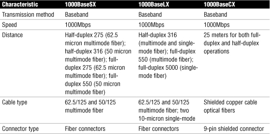
Table 21 Summary of 1000BaseT Characteristics
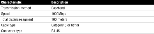
Table 22 Summary of 802.3ae Characteristics
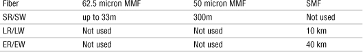
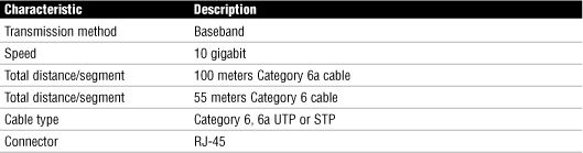
Table 23 Summary of 802.3an Characteristics
WAN Technology Switching Methods
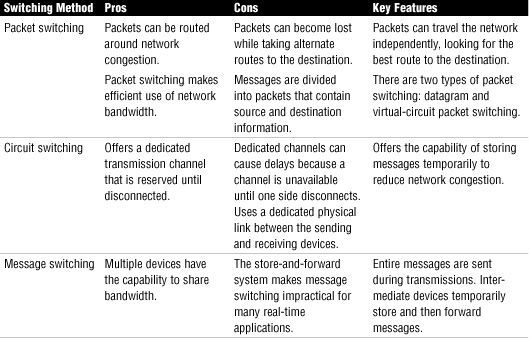
Table 24 Comparison of Switching Methods
T/E/J Carriers
Table 25 Comparing T/E/J Carriers
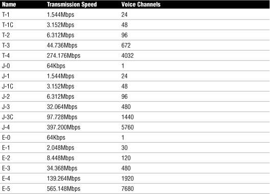
Fractional Lines
• Because of the cost of a T-carrier solution, it is possible to lease portions of a T-carrier service. Known as fractional T, you can subscribe and pay for service based on 64Kbps channels.
xDSL Internet Access
• Asymmetric DSL (ADSL)—The word asymmetric describes different channels on the line: One channel is used for POTS and is responsible for analog traffic, the second channel is used to provide upload access, and the third channel is used for downloads. With ADSL, downloads are faster than uploads.
• Symmetric DSL (SDSL)—SDSL offers the same speeds for uploads and for downloads, making it most suitable for business applications such as web hosting, intranets, and e-commerce. It is not widely implemented in the home/small business environment and cannot share a phone line.
• ISDN DSL (IDSL)—ISDN DSL is a symmetric type of DSL commonly used in environments where SDSL and ADSL are unavailable. IDSL does not support analog phones.
• Rate Adaptive DSL (RADSL)—RADSL is a variation on ADSL that can modify its transmission speeds based on the signal quality. RADSL supports line sharing.
• Very High Bit Rate DSL (VHDSL)—VHDSL is an asymmetric version of DSL and, as such, can share a telephone line.
• High Bit Rate DSL (HDSL)—HDSL is a symmetric technology that offers identical transmission rates in both directions. HDSL does not allow line sharing with analog phones.
• The term broadband refers to high-speed Internet access. Both DSL and cable modem are common broadband Internet technologies. Broadband routers and broadband modems are network devices that support both DSL and cable.
Cable Internet Access
Cable Internet access is an always-on Internet access method available in areas that have digital cable television.
A cable modem is generally equipped with a medium-dependent interface crossed (MDI-X) port, so a straight-through UTP cable can be used to connect the modem to a system.
SONET/OCx Levels
Table 26 OCx Levels and Transmission Rates
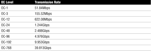
MPLS
• Multiprotocol Label Switching (MPLS) is a technology designed to speed up network traffic flow by moving away from the use of traditional routing tables.
• Instead of the routing tables, MPLS uses short labels to direct packets and forward them through the network.
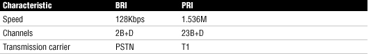
BRI and PRI ISDN Comparison
Table 27 compares BRI and PRI ISDN.
Table 27 BRI and PRI ISDN Comparison
Network Devices
For the CompTIA Network+ exam, 17% of the content will be focused on Domain 3, Network Devices. This domain deals with the key devices we use on networks. This includes routers, gateways, servers, bridges, APs, and the like. Domain 3 is covered in Chapters 3 and 7.
Hubs and Switches
• Computers connect to a hub via a length of twisted-pair cabling.
• Active hubs regenerate a data signal before forwarding it to all the ports on the device and require a power supply.
• Passive hubs, which today are seen only on older networks, do not need power and they don’t regenerate the data signal.
• A hub takes data from one of the connected sending devices and forwards the message to all the other ports on the hub.
• The method of sending data to all systems regardless of the intended recipient is referred to as broadcasting. On busy networks, broadcast communications can have a significant impact on overall network performance.
• A hub forwards data to all ports, regardless of whether the data is intended for the system connected to the port. Rather than forwarding data to all the connected ports, a switch forwards data only to the port on which the destination system is connected.
• By channeling data only to the connections that should receive it, switches reduce the number of collisions that happen on the network.
• A switch makes forwarding decisions based on the Media Access Control (MAC) addresses of the devices connected to it to determine the correct port.
• In cut-through switching, the switch begins to forward the packet as soon as it is received.
• In store-and-forward switching, the switch waits to receive the entire packet before beginning to forward it.
• In fragment-free switching, the switch reads only the part of the packet that enables it to identify fragments of a transmission.
• Switches reduce collisions by a process called microsegmentation. Each port on a switch is a dedicated link between the switch and the connected computer.
The following facts are relevant to both hubs and switches:
• Hubs and switches have two types of ports: medium-dependent interface (MDI) and medium-dependent interface crossed (MDI-X).
• A straight-through cable is used to connect systems to the switch or hub using the MDI-X ports.
• In a crossover cable, pins 1 and 3 and pins 2 and 6 are crossed.
• Both hubs and switches use light-emitting diodes (LEDs) to indicate certain connection conditions. At the very least, a link light on the hub indicates the existence of a live connection.
• Both hubs and switches are available in managed and unmanaged versions. A managed device has an interface through which it can be configured to perform certain special functions.
• Bridges are used to divide up networks and thus reduce the amount of traffic on each network.
• A bridge functions by blocking or forwarding data, based on the destination MAC address written into each frame of data.
• Unlike bridges and switches, which use the hardware-configured MAC address to determine the destination of the data, routers use software-configured network addresses to make decisions.
• With distance-vector routing protocols, each router communicates all the routes it knows about to all other routers to which it is directly attached.
• Routing Information Protocol (RIP) is a distance-vector routing protocol for both Transmission Control Protocol (TCP) and Internetwork Packet Exchange (IPX).
• Modems translate digital signals from a computer into analog signals that can travel across conventional phone lines.
• Modems are controlled through a series of commands known as the Hayes AT command set.
Table 28 AT Commands Used with Dial-Up Modems
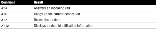
Table 29 is a summary of UART chip speeds.
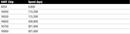
Power over Ethernet (PoE)
• PoE is a technology that allows electrical power to be transmitted over twisted-pair ethernet cable.
• The power is transferred, along with data, to provide power to remote devices. These devices may include remote switches, wireless access points, VoIP equipment, and so on.
Trunking
• The term trunking refers to the use of multiple network cables or ports in parallel to increase the link speed beyond the limits of any one single cable or port.
Port Mirroring
• Port mirroring provides a way to monitor network traffic and monitor how well a switch is working.
• To use port mirroring, administrators configure a copy of all inbound and outbound traffic to go to a certain port. A protocol analyzer is used to examine the data sent to the port and therefore is not interrupting the flow of regular traffic.
Port Authentication
• Port authentication involves authenticating users on a port by port basis. One standard that specifies port authentication is the 802.1X standard, often associated with wireless security.
Types of Bridges
Three types of bridges are used in networks. You don’t need detailed knowledge of how each bridge works, but you should have an overview:
• Transparent bridge—A transparent bridge is invisible to the other devices on the network. Transparent bridges perform only the function of blocking or forwarding data based on the MAC address; the devices on the network are oblivious to these bridges’ existence. Transparent bridges are by far the most popular types of bridges.
• Translational bridge—A translational bridge can convert from one networking system to another. As you might have guessed, it translates the data it receives. Translational bridges are useful for connecting two different networks, such as ethernet and token-ring networks. Depending on the direction of travel, a translational bridge can add or remove information and fields from the frame as needed.
• Source-route bridge—Source-route bridges were designed by IBM for use on token-ring networks. The source-route bridge derives its name from the fact that the entire route of the frame is embedded within the frame. This allows the bridge to make specific decisions about how the frame should be forwarded through the network. The diminishing popularity of token ring makes the chances that you’ll work with a source-route bridge very slim.
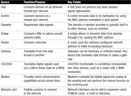
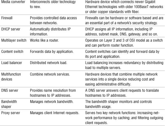
Network Devices Summary
Table 30 Network Devices Summary
Access Point Coverage
• APs have a limited transmission distance. This limitation is an important consideration when deciding where an AP should be placed on the network.
• When troubleshooting a wireless network, pay close attention to the distance client systems are away from the AP.
• When faced with a problem where client systems cannot consistently access the AP, you could try moving the access point to better cover the area, but then you may disrupt access for users in other areas.
• Wireless signals degrade depending on the construction material used. Signals passing through concrete and steel are particularly weakened.
If you are troubleshooting a wireless connection that has a particularly weak signal, you can do a few things to help increase the power of that signal:
• Antenna—Perhaps the first and most obvious thing to do is to make sure that the antenna on the AP is positioned for best reception.
• Device placement—One factor that can degrade wireless signals is RF interference. Because of this, it is important to try to keep wireless devices away from appliances that output RF noise. This includes microwaves, certain cordless devices using the same frequency such as phones, and electrical devices.
• Network location—Although there may be limited choice, as much as possible it is important to try to reduce the number of obstructions that the signal must pass through. Every obstacle strips a little more power from the signal. The type of material a signal must pass through also can have a significant impact on the signal integrity.
• Boost signal—If all else fails, it is possible to purchase devices, such as wireless repeaters, that can amplify the wireless signal. The device takes the signal and amplifies it so that it has greater strength. This also increases the distance that the client system can be placed from the AP.
Wireless client connectivity connections include the following:
• SSID—The Service Set Identifier (SSID) is a configurable client identification that allows clients to communicate to a particular base station.
• Channel—Each client must use the same wireless channel.
• SSID Broadcast—In their default configuration, wireless access points typically broadcast the SSID name into the air at regular intervals.
• Authentication—Clients must be configured to use the same authentication type. This may be WEP or WPA.
• Wireless mode—To access the network, the client must use the same wireless mode as the AP.
• Network type—This is where the network can be set to use the ad hoc or infrastructure network design.
Network Management
For the CompTIA Network+ exam, 20% of the content will be focused on Domain 4, Network Management. This domain deals with the OSI model, documentation, fault tolerance, and troubleshooting best practices. Domain 4 is covered in Chapters 9, 10, 11, and 13.
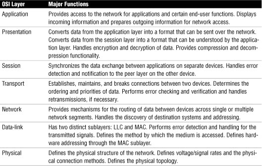
OSI Model Review
Table 31 Summary of the OSI Model
When you take the Network+ exam, you may be asked to identify at what level of the OSI model common network devices operate. This information is provided in Table 32.
Table 32 Mapping Devices to the OSI Model
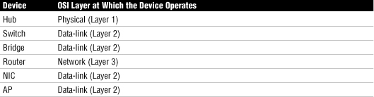
• Application protocols map to the application, presentation, and session layers of the OSI model. Application protocols include FTP, TFTP, SFTP, SSH, Telnet, SCP, NNTP, NTP, and SNMP.
• Transport protocols map to the transport layer of the OSI model and are responsible for the transporting of data across the network. Transport protocols include NetBEUI, SPX, TCP, and UDP.
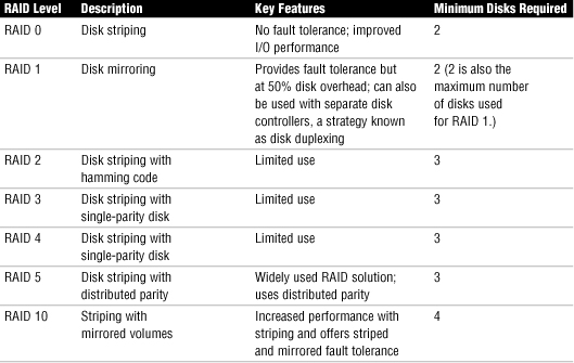
Fault Tolerance and Disaster Recovery
Fault tolerance involves ensuring that when network hardware or software fails, users on the network can still access the data and continue working with little or no disruption of service. One of the most common fault-tolerance solutions is RAID. Table 33 shows various RAID solutions.
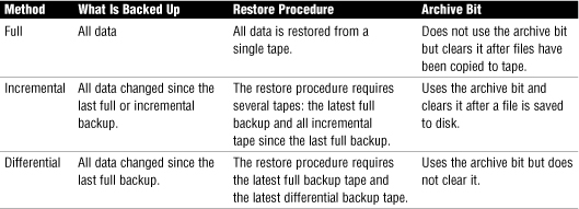
Backups
Table 34 describes various backup strategies.
Table 34 Summary of Backup Strategies
• Use an offsite tape rotation scheme to store current copies of backups in a secure offsite location.
• Periodically introduce new tapes into the tape rotation and destroy the old tapes.
Methods Used for Traffic Shaping
Some common traffic shaping methods include the following:
• Shaping by application—Administrators can control traffic based on the types of network traffic and by assigning that category a bandwidth limit.
• Shaping network traffic per user—It is possible to establish traffic shaping on a per-user basis.
• Priority shaping—One important consideration when looking at traffic shaping is determining which traffic is mission critical and which is less so.
Documentation Procedures
Some elements will always be included in quality documentation:
• Network topology—Networks can be complicated, and if someone new is looking over the network, it is important to document the entire topology.
• Wiring layout—Much of the network wiring is hidden behind walls and ceilings, making it hard to know where wiring is and what wiring is being used on the network. This makes it critical to have up-to–date information on network wiring.
• Server configuration—Documentation must include schematic drawings of where servers are located on the network and the services each provides.
• Key applications—Documentation will also include all key applications used on the network.
• Detailed account of network services—Services such as DNS, DHCP, RAS, and so on are an important part of documentation.
• Network procedures—Documentation should include information on network policy and procedures.
Physical and Logical Network Diagrams
• In addition to the wiring schematics, documentation should also include diagrams of the physical and logical network design. The physical topology refers to how a network is physically constructed; that is, how it actually looks.
• The logical topology refers to how a network looks to the devices that use it; in other words, how it actually functions.
• The physical documentation of the network would include such elements as
• Cabling information—A visual description of all the physical communication links, including all cabling, the cables grade, cable lengths, WAN cabling, and so on.
• Servers—The physical network diagram would include the server names and IP addresses, type of server, and domain membership.
• Network devices—The physical diagram must include the location of the devices on the network. This would include the printers, hubs, switches, routers, gateways, and so on.
• Wide area network—The physical network would also include the location and devices of the WAN network and components.
• User information—The diagram may include some user information, including the number of local and remote users.
• The logical network refers to the direction that data actually flows on the network within the physical topology. The logical diagram is not intended to focus on the hardware of the network but rather how data flows through that hardware.
• In addition to data flow, logical diagrams may include additional elements such as the network domain architecture, server roles, protocols used, and so on.
Baselines
• The purpose of a baseline is to provide a basis for comparison.
• To be of any use, baselining is not a one-time task; rather, baselines should be taken periodically to be able to provide an accurate comparison.
• Baselines need to be taken periodically and under the same conditions to be effective. They provide a means to compare current performance with past performance to help determine if the network is functioning properly or if troubleshooting is required.
Network Policies, Procedures, Configurations, and Regulations
• Network policies dictate network rules and provide guidelines for network conduct. Policies are updated and reviewed often and changed to reflect changes to the network.
• Network procedures differ from policies in that they identify the way in which tasks are to be performed.
• It is important to keep documentation on both the software and hardware configuration on the network.
• Regulations are often enforceable by law.
Network Performance, Load and Stress Testing
• The goal of performance testing is to establish baselines for the comparison of network functioning. It tests the current performance rate of the network.
• Load tests involve putting an exaggerated load on the network infrastructure and applications; they are sometimes done to see if bugs exist in the network that are not currently visible under the current load.
• Whereas load tests do not try to break the system under intense pressure, stress tests sometimes do. They are used to push resources to the limit or over the limit.
• With stress tests, administrators can test recovery procedures and monitor the network under extreme conditions.
System Logs, Security Logs, History Logs and Event Logs
• A systems security log contains events related to security incidents, such as successful and unsuccessful logon attempts and failed resource access.
• Security logs are customizable, meaning that administrators can fine-tune exactly what they want to monitor.
• The application log contains information logged by applications that run on a particular system rather than the operating system itself.
• Vendors of third-party applications can use the application log as a destination for error messages generated by their applications.
• The application log works in much the same way as the security log. It tracks events within applications, both successful events and failed events.
• This is the place to look when you’re troubleshooting a problem with a hardware device on your system or a problem with network connectivity.
• History logs are a compilation of events from other log files. One history log may contain all significant events over the past year from the security log on a server.
• History logs are critical because they provide a detailed account of alarm events that can be used to track trends and locate problem areas in the network.
Troubleshooting Wiring
• Part of troubleshooting wiring problems is to identify where the cable is run to isolate whether the problem is a result of cross talk or EMI. Be aware of problems associated with interference and the distance limitations of the cable being used.
• Cross talk—Whether its coaxial cable, or UTP, copper-based cabling is susceptible to cross talk. Cross talk happens when the signal from one cable gets mixed up with the signal in another cable. This can happen when cables are run too closely together. Cables, such as coaxial and twisted pair, can use shielding to help reduce the impact of cross talk.
• Near end cross talk—Another form of cross talk is referred to as near end cross talk, or NEXT. NEXT occurs when connectors are not properly attached to UTP cable. Specifically, the cross talk can occur if the wires pushed into the RJ-45 connector are crossed or crushed.
• Electromagnetic interference (EMI)—EMI occurs when cables are run too close to everyday office fixtures such as computer monitors, fluorescent lighting fixtures, elevators, microwaves, and anything else that creates an electromagnetic field.
• Attenuation—All media has recommended lengths for the run of the cable. This is because data signals weaken as they travel farther from the point of origin. If the signal travels far enough, it can weaken so much that it becomes unusable. The weakening of data signals as they traverse the media is called attenuation.
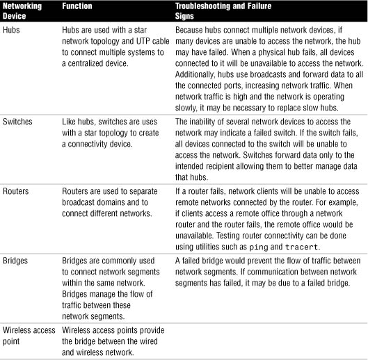
Troubleshooting Infrastructure Hardware
Table 35 Common Network Hardware Components, Their Function, and Troubleshooting Strategies
Steps in the Network Troubleshooting Methodology
1. Information gathering—identify symptoms and problems.
2. Identify the affected areas of the network.
3. Determine if anything has changed.
4. Establish the most probable cause.
5. Determine if escalation is necessary.
6. Create an action plan and solution identifying potential effects.
7. Implement and test the solution.
8. Identify the results and effects of the solution.
9. Document the solution and the entire process.
Network Tools
For the CompTIA Network+ exam, 12% of the content will be focused on Domain 5, Network Tools. This domain deals with the command-line utilities and the tools we use on networks, both hardware and software. Domain 5 is covered in Chapter 12 and 13.
Wire Crimpers, Strippers, and Snips
• A wire crimper is a tool that you use to attach media connectors to the ends of cables. For instance, you use one type of wire crimper to attach RJ-45 connectors on unshielded twisted-pair (UTP) cable, and you use a different type of wire crimper to attach British Naval Connectors (BNCs) to coaxial cabling.
• Wire strippers come in a variety of shapes and sizes. Some are specifically designed to strip the outer sheathing from coaxial cable, whereas others are designed to work with UTP cable.
• Any type of stripper is designed to cleanly remove the sheathing from the wire to make sure a clean contact can be made.
• Wire snips are tools designed to cleanly cut the cable. Sometimes network administrators will buy cable in bulk and use wire snips to cut the cable into desired lengths. The wire strippers are then used to prepare the cable for the attachment of the connectors.
• Punch-down tools are used to attach twisted-pair network cable to connectors within a patch panel. Specifically, they connect twisted-pair wires to the IDC.
Voltage Event Recorder, Temperature Monitors
• Voltage event recorders are used to monitor the quality of power used on the network or by network hardware.
• Voltage event recorders are used to identify potential power-related concerns such as power sags, spikes, surges, or other power variations.
• Temperature monitors keep track of temperature in wiring closets and server rooms.
• If server room temperature rises too high, or dips too low, automatic alerts are set the warning administrators of a situation before equipment can be damaged.
Network Hardware Tools
• The purpose of the tone probe is to generate a signal that is transmitted on the wire you are attempting to locate. At the other end, you press the tone locator against individual wires. When it makes contact with the wire that has the signal on it, the locator emits an audible signal or tone.
• Toner probes are specifically used for locating cables hidden in floors, ceilings, or walls, and for tracking cables from the patch panel to their destination.
• Protocol analyzers can be hardware or software based. Their primary function is to analyze network protocols such as TCP, UPD, HTTP, FTP, and so on.
• Protocol analyzers will help diagnose computer networking problems, alert you of unused protocols, identify unwanted or malicious network traffic, and help isolate network traffic related problems.
• Protocol analyzers allow administrators to examine the bandwidth that a particular protocol is using.
• A time domain reflectometer (TDR) is a device used to send a signal through a particular media to check the continuity of the cable.
• Good quality TDRs have the capability to locate many types of cabling faults, such as a severed sheath, damaged conductors, faulty crimps, shorts, loose connectors, and so on.
• TDRs work on the physical layer of the OSI model, sending a signal through a length of cable looking for cable faults.
• An optical time-domain reflectometer (OTDR) performs the same basic function as a wire media tester, but on optical media.
• The most common problem with an optical cable is a break in the cable that prevents the signal from reaching the other end. Because of the extended distances that can be covered with fiber-optic cables, degradation is rarely an issue in a fiber-optic LAN environment.
• A basic multimeter combines several electrical meters into a single unit offering the capability to measure voltage, current, and resistance. Advanced models can also measure temperature.
Packet Sniffers
• Packet sniffers are commonly used on networks. They are either a hardware device or software that eavesdrops on transmissions that are traveling throughout the network.
Throughput Testing
• In the networking world, throughput refers to the rate of data delivery over a communication channel. Any throughput tester is designed to quickly gather information about network functioning and specifically, the average overall network throughput.
Port Scanners
• Port scanners are a software-based utility and security tool designed to search a network host for open ports on a TCP/IP-based network.
• The netstat –a command can be used on a Windows-based system to see the status of ports.
Network Security
For the CompTIA Network+ exam, 11% of the content will be focused on Domain 6, Network Security. This domain deals with security devices, firewalls, security protocols, and authentication. Domain 6 is covered in Chapters 14 and 15.
Firewalls
• A firewall is considered a logical security measure and one of the cornerstone concepts for network security.
• A firewall is a system or group of systems that controls the flow of traffic between two networks.
• At its most basic, a firewall is a device that has more than one network interface and manages the flow of network traffic between those interfaces.
A firewall can employ a variety of methods to ensure security. In addition to the role just described, modern firewall applications can also perform a range of other functions, often through the addition of add-on modules. These functions may include the following:
• Content filtering—Most firewalls can be configured to provide some level of content filtering. This can be done for both inbound and outbound content.
• Signature identification—A signature refers to a unique identifier for a particular application.
• Virus scanning services—As web pages are downloaded, content within the pages can be checked for viruses.
• Network address translation (NAT)—Many firewalls have the capability to provide NAT functionality to the network.
• URL filtering—By using a variety of methods, the firewall can choose to block certain websites from being accessed by clients within the organization.
• Bandwidth management—Although required only in certain situations, bandwidth management can prevent a certain user or system from hogging the network connection.
• Stateful firewalls monitor data traffic streams from one end to the other.
• A stateful firewall will refuse unsolicited incoming traffic that does not comply with dynamic or preconfigured firewall exception rules.
• A stateful firewall tracks the state of network connections watching data traffic, including monitoring source and destination addresses and TCP and UDP port numbers.
Packet-Filtering Firewalls
• Packet filtering enables the firewall to examine each packet that passes through it and determine what to do with it, based on the configuration.
• A packet-filtering firewall deals with packets at the network layers (Layer 3) of the OSI model and sometimes data-link (Layer 2).
The following are some of the criteria by which packet filtering can be implemented:
• IP address—By using the IP address as a parameter, the firewall can allow or deny traffic, based on the source or destination IP address.
• Port number—TCP/IP suite uses port numbers to identify which service a certain packet is destined for. By configuring the firewall to allow certain types of traffic, you can control the flow.
• Protocol ID—Because each packet transmitted with IP has a protocol identifier in it, a firewall can read this value and then determine what kind of packet it is.
• MAC address—This is perhaps the least used of the filtering methods discussed, but it is possible to configure a firewall to use the hardware-configured MAC address as the determining factor in whether access to the network is granted.
Circuit-Level Firewalls
• Circuit-level firewalls are similar in operation to packet-filtering firewalls, but they operate at the transport and session layers of the OSI model.
• The biggest difference between a packet-filtering firewall and a circuit-level firewall is that a circuit-level firewall validates TCP and UDP sessions before opening a connection, or circuit, through the firewall.
• When the session is established, the firewall maintains a table of valid connections and lets data pass through when session information matches an entry in the table. The table entry is removed, and the circuit is closed when the session is terminated.
Application-Layer Firewalls
• As the name suggests, application-layer firewalls operate at the application layer of the OSI model.
• In operation, application-layer firewalls can inspect data packets traveling to or from an application. This allows the firewall to inspect, modify, block, and even redirect data traffic as it sees fit.
Demilitarized Zones
• A DMZ is part of a network on which you place servers that must be accessible by sources both outside and inside your network.
• The DMZ is not connected directly to either network, and it must always be accessed through the firewall. The military term DMZ is used because it describes an area in which little or no enforcement or policing exists.
• Using DMZs provides an extra level of flexibility, protection, and complexity to your firewall configuration.
Intrusion Detection System (IDS) and Intrusion Prevention System (IPS)
• The IDS compares the traffic it monitors to predefined parameters and rules; traffic in violation of these rules is flagged as potentially dangerous.
• The IDS can detect malware or other dangerous traffic that may pass undetected by the firewall. Most IDS systems can detect potentially dangerous content by its signature.
• A typical IDS will log incidents and store these in a database for review.
• An IPS is a network device whose purpose is to continually scan the network, looking for inappropriate activity, and shut down any potential threats.
• The IPS scans, looking for any known signatures of common attacks and automatically tries to prevent those attacks. An IPS is considered a reactive security measure because it actively monitors and can take steps to correct a potential security threat.
Access Control Lists (ACL)
• An ACL typically refers to specific access permissions assigned to an object or device on the network. For example, wireless routers can be configured to restrict who can and cannot access the router based on MAC addresses.
• Another form of access control may be the permissions set on a network printer. The permissions may allow printer access only to a certain network group, whereas another can’t access the printer.
Port Blocking/Filtering
• Port blocking is associated with firewalls and proxy servers, although in fact it can be implemented on any system that provides a means to manage network data flow, according to data type.
• When a port is blocked, you disable the capability for traffic to pass through that port, thereby filtering that traffic.
• Port blocking is typically implemented to prevent users on a public network from accessing systems on a private network, although it is equally possible to block internal users from external services, and internal users from other internal users, by using the same procedure.
Table 36 Commonly Opened Port Numbers and Their Associated Uses
Tunneling and Encryption
• A VPN extends a LAN by establishing a remote connection, a connection tunnel, using a public network such as the Internet.
• A VPN provides a point-to-point dedicated link between two points over a public IP network.
• VPN encapsulates encrypted data inside another datagram that contains routing information. The connection between two computers establishes a switched connection dedicated to the two computers. The encrypted data is encapsulated inside PPP, and that connection is used to deliver the data.
PPTP and L2TP
• PPTP creates a secure tunnel between two points on a network, over which other connectivity protocols, such as PPP, can be used. This tunneling functionality is the basis for VPNs.
• VPNs are created and managed by using the PPTP protocol, which builds on the functionality of PPP, making it possible to create dedicated point-to-point tunnels through a public network such as the Internet.
• PPTP uses authentication methods, including MS-CHAP, CHAP, PAP, and EAP.
• L2TP authenticates the client in a two-phase process: It first authenticates the computer and then the user.
• By authenticating the computer, it prevents the data from being intercepted, changed, and returned to the user in what is known as a man-in-the-middle attack.
• L2TP assures both parties that the data they are receiving is exactly the data sent by the originator.
IPsec
• IPsec is an IP-layer security protocol designed to provide security against internal and external attacks.
• To create secure data transmissions, IPsec uses two separate protocols: Authentication Headers (AH) and Encapsulating Security Payloads (ESP).
• AH is primarily responsible for the authentication and integrity verification of packets, whereas ESP provides encryption services.
• Because they are independent protocols, when implementing an IPsec policy, you can use them together or individually.
Remote Access Service (RAS)
• RAS is a remote access solution included with Windows Server products. RAS is a feature-rich, easy-to-configure, and easy-to-use method of configuring remote access.
• Any system that supports the appropriate dial-in protocols, such as PPP, can connect to a RAS server. Connection to a RAS server can be made over a standard phone line, using a modem, over a network, or via an ISDN connection.
• RAS supports remote connectivity from all the major client operating systems available today, including all newer Windows OSs:
• Windows Server products
• Windows XP/Vista Home-based clients
• Windows XP/Vista Professional-based clients
• UNIX-based/Linux clients
• Macintosh-based clients
• Although the system is called RAS, the underlying technologies that enable the RAS process are dial-up protocols such as Serial Line Internet Protocol (SLIP) and Point-to-Point Protocol (PPP).
SLIP, PPP, and PPoE
• SLIP was designed to allow data to be transmitted via TCP/IP over serial connections in a UNIX environment.
• SLIP does not support encryption nor authentication. It transmits all the data used to establish a connection (username and password) in clear text.
• PPP provides a number of security enhancements compared to regular SLIP. The most important is the encryption of usernames and passwords during the authentication process.
• PPP can use a variety of LAN protocols to establish a remote link.
• Point-to-Point Protocol over Ethernet (PPPoE) is a protocol used for connecting multiple network users on an ethernet local area network to a remote site through a common device.
• PPPoE is a combination of PPP and the ethernet protocol, which supports multiple users in a local area network.
• With PPPoE, a number of users can share the same physical connection to the Internet, and in the process, PPPoE provides a way to keep track of individual user Internet access times.
Remote Control Protocols
• RDP protocol allows client systems to access and run applications on a server, using the resources of the server, with only the user interface, keystrokes, and mouse movement being transferred between the client and server computers.
• Virtual network computing (VNC) consists of a client, a server, and a communication protocol. It is another system whereby a remote user can access the screen of another computer system. As with the other systems mentioned here, VNC allows remote login, where clients can access their own desktop while being physically away from their computer.
• VNC uses a protocol known as the remote framebuffer (RFB) protocol. RFB is the backbone allowing remote access to another systems graphical interface.
• The Citrix Independent Computing Architecture (ICA) allows clients to access and run applications on a server, using the resources of the server with only the user interface, keystrokes, and mouse movements being transferred between the client system and the server.
Authentication, Authorization, and Accountability (AAA)
• AAA defines a spectrum of security measures, policies, and procedures that are combined to create a secure network.
• Authentication refers to the mechanisms used to verify the identity of the computer or user attempting to access a particular resource.
• Several forms of authentication are used on today’s networks. A password-username combination is typically the most common form of authentication; however, other types of authentication include smart cards, biometrics, and voice recognition.
• The types of authentication methods can be combined, requiring multiple authentication methods to access a system. Combining two authentication methods is known as a two-factor authentication, and combining more is known as multifactor authentication.
• Authorization is the method used to determine if an authenticated user has access to a particular resource. This is commonly determined through group association—that is, a particular group may have a specific level of security clearance.
• Accountability refers to the tracking mechanisms used to keep a record of events on a system.
• One tool often used for this purpose is known as auditing. Auditing refers to the process of monitoring events on a system and keeping a log of what has occurred.
• Auditing increases accountability on a network by making it possible to isolate events to certain users.
TACACS+
• Terminal Access Controller Access Control System+ (TACACS+) is a security protocol designed to provide centralized validation of users who are attempting to gain access to a router or Network Access Server (NAS).
• Like RADIUS, TACACS+ is a set of security protocols designed to provide AAA of remote users.
• TACACS uses TCP port 49 by default.
• TACACS+ relies on TCP for connection oriented delivery, whereas RADIUS uses connectionless UDP for data delivery.
Kerberos Authentication
• Kerberos is an Internet Engineering Task Force (IETF) standard for providing authentication and is an integral part of network security.
• Kerberos is one part of a strategic security solution that provides secure authentication services to users, applications, and network devices by eliminating the insecurities caused by passwords being stored or transmitted across the network.
• Kerberos is used primarily to eliminate the possibility of a network eavesdropper from tapping into data over the network, and particularly usernames and passwords.
• Kerberos ensures data integrity and blocks tampering on the network. It employs message privacy (encryption) to ensure messages are not visible to eavesdroppers on the network.
• Kerberos is a nonproprietary protocol used for cross-platform authentication; it uses port 88.
• The security tokens used in Kerberos are known as tickets.
Public Key Infrastructure (PKI)
• A public key infrastructure (PKI) is a collection of software, standards, and policies that are combined to allow users from the Internet or other unsecured public networks to securely exchange data.
• PKI uses a public and a private cryptographic key pair that is obtained and shared through a trusted authority. There are services and components working together to develop the PKI.
• Some of the key components of a PKI include certificates, certificate authorities, certificate templates, and certification revocation lists.
Public Keys and Private Keys
• Public key—A nonsecret key that forms half of a cryptographic key pair that is used with a public key algorithm. The public key is freely given out to all potential receivers.
• Private key—The secret half of a cryptographic key pair that is used with a public key algorithm. The private part of the public key cryptography system is never transmitted over a network.
• Keys can be used in two ways to secure data communications:
• Public (asymmetric) key encryption uses both a private and a public key to encrypt and decrypt messages. The public key is used to encrypt a message or verify a signature, and the private key is used to decrypt the message or to sign a document.
• Private (symmetric) key encryption uses a single key for both encryption and decryption. If a person possesses the key, he or she can both encrypt and decrypt messages. Unlike public keys, this single secret key cannot be shared with anyone except people who should be permitted to decrypt as well and encrypt messages.
Certificates
• A certificate is a digitally signed statement that associates the credentials of a public key to the identity of the person, device, or service that holds the corresponding private key.
• Certificates can provide a number of security services, including authentication, encryption, and digital signatures.
Remote Authentication Protocols
The authentication protocols include the following:
• Microsoft Challenge Handshake Protocol (Microsoft-CHAP)—MS-CHAP is used to authenticate remote Windows workstations. MS-CHAP works with PPP, PPTP, and L2TP network connections. MS-CHAP uses a challenge/response mechanism to keep the password from being sent during the authentication process. MS-CHAP uses the Message Digest 5 (MD5) hashing algorithm and the Data Encryption Standard (DES) encryption algorithm.
• Microsoft Challenge Handshake Authentication Protocol (MS-CHAP v2)—Support for two-way authentication and a few changes in how the cryptographic key is analyzed. As far as authentication methods are concerned, MS-CHAP version 2 is the most secure.
• Extensible Authentication Protocol (EAP)—EAP is an extension of PPP that supports authentication methods that go beyond the simple submission of a user name and password.
• Challenge Handshake Authentication Protocol (CHAP)—CHAP supports non-Microsoft remote access clients. CHAP allows for authentication without actually having the user send the password over the network, and because it’s an industry standard, it allows Windows Server 2003 to behave as a remote client to almost any third-party PPP server.
• Password Authentication Protocol (PAP)—PAP is a simple authentication protocol in which the username and password are sent to the remote access server in unencrypted text, making it possible for anyone listening to network traffic to steal both.
Physical Security
• Physical security refers to the issues related to the physical security of the equipment that comprises or is connected to the network.
• Physical security measures include controlling access to equipment, supervising visitors, controlling physical access to areas that contain networking equipment, and ensuring that removable media such as backup tapes are transported and stored securely.
• Logical security is concerned with security of data held on devices connected to the network.
• Logical security involves controlling passwords and password policies, controlling access to data on servers through file system security, controlling access to backup tapes, and perhaps most importantly, preventing sources outside the network from gaining access to the network through a connection from another network, such as the Internet.
Using Secure Protocols
There are many protocols we use to move information throughout networks. Some of these protocols are secure whereas others offer little and sometimes no security at all.
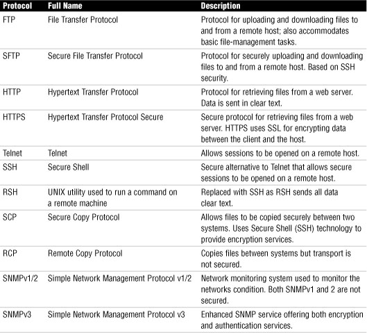
Malicious Software
The term malware is a term used to describe a variety of different software threats. Some of these threats include
• Viruses
• Macro viruses
• Worms
• Trojan horses
• Spyware
Table 38 Comparing Malware Types
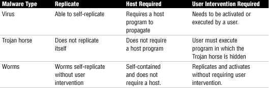
Denial of Service and Distributed Denial of Service Attacks
Denial of Service (DoS) attacks are designed to tie up network bandwidth and resources and eventually bring the entire network to a halt.
• Fraggle—In a Fraggle attack, spoofed UDP packets are sent to a network’s broadcast address. These packets are directed to specific ports such as port 7 or port 19 and after they are connected, they can flood the system.
• Smurf—The Smurf attack is similar to a Fraggle attack except that a ping request is sent to a broadcast network address with the sending address spoofed so many ping replies will come back to the victim and overload the ability of the victim to process the replies.
• Ping of death—With this attack, an oversized ICMP datagram is used to crash IP devices that were manufactured before 1996.
• SYN flood—In a typical TCP session, communication between two computers is initially established by a three-way handshake referred to as SYN, SYN/ACK, ACK. At the start of a session, the client sends a SYN message to the server. The server acknowledges the request by sending a SYN/ACK message back to the client. The connection is established when the client responds with an ACK message.