Part I. Exam Preparation
Chapter 1 Introduction to Networking
Chapter 2 Media and Connectors
Chapter 3 Networking Components and Devices
Chapter 4 Understanding the TCP/IP Protocols Suite
Chapter 5 TCP/IP Addressing and Routing
Chapter 6 Ethernet Networking Standards
Chapter 8 Wide Area Networking
Chapter 10 Network Performance and Optimization
Chapter 11 Troubleshooting Procedures and Best Practices
Chapter 12 Command-Line Networking Tools
Chapter 13 Network Management Tools and Documentation Procedures
Chapter 14 Network Access Security
Chapter 15 Security Technologies and Malicious Software
Chapter One
Introduction to Networking
Introduction
By itself, the computer sitting on your desk is a powerful personal and business tool. Link that system with 1, 2, or even 1,000 other computers, and the possibilities and potential of your system become almost endless. That is the nature of networking.
Companies of all sizes depend on a collection of interconnected computers to conduct business. These computer networks make possible most of the applications and services used in corporate and home environments. Email, print sharing, real-time communication, file sharing, and videoconferencing would all be unavailable (or pointless) without networks.
The CompTIA Network+ exam is designed to prepare people to work with and around computer networks. The CompTIA objectives introduce basic networking concepts and design, laying the foundation for a solid, comprehensive understanding of networking fundamentals. This book closely follows the CompTIA objectives, clearly explaining each objective and highlighting the important concepts that are most likely to appear on the exam.
This chapter examines some of the fundamental principles that affect modern networking. These include a discussion about peer-to-peer and client/server computing and the differences between local area networks (LAN), wide area networks (WAN), and metropolitan area networks (MAN). This chapter also looks at network topologies, the physical and logical arrangements of devices on a network, and how they can affect the basic layout and makeup of a network.
What Is a Network?
By definition, a network is a group of connected computers. The group can be as small and simple as two computers and a printer set up in a house or as large and complex as a multisite network that supports thousands of computers and hundreds of printers and other devices. Regardless of the size and complexity of a network, its fundamental function is to allow you to communicate and share data and resources.
Although the basic purpose of a network has not changed since the first network was created, the way in which we build and use networks has evolved in an amazing way. In a not-too-distant past, networks were a luxury that only the largest companies and governments could afford, but they now have become a vital business tool that hundreds of millions of people rely on every day.
Note
The Internet It might seem as though a small network in your house is very different from a network such as the Internet, but you would be surprised how much the two have in common. For example, the PCs on a home network most likely communicate in the same way as systems on the Internet. Also, the Internet has clients and servers just like a small network might have. The Internet uses certain devices, such as network routers, that are not as common in a home network, but the basic building blocks of both networks are the same. In fact, the term Internet is derived from the term internetwork, which is used to describe a group of connected networks.
The operation of a network should be transparent to the people who use it. Users should, for example, be able to print to a printer connected to the network just as easily as if it were attached to their own PCs. They should also be able to access files this easily. The degree of transparency of a network depends on how good the network’s structure is and, to a certain extent, how well the network is managed. (But no matter how well a network is managed, problems will occasionally crop up.)
If the purpose of a network is to share resources among computer systems, what types of information and services are shared on a network—and why? All networks, regardless of their design or size, perform one or all of a number of network functions. The following are some common reasons for implementing a network:
• Communication—Increased communication is one of the primary purposes of a network. Networks allow a variety of communications, including videoconferencing, real-time chats, and email. Many organizations have grown so dependent on network communications that without it, they cannot function.
• Sharing hardware—Printing is the best example of hardware sharing. Without a network, each computer that requires printing capabilities would need a printer connected directly to it—and that would be impractical and costly. Although printers are almost certainly the most popular devices shared on networks, other devices are often shared as well, including scanners, CD-ROM drives, tape drives, and other removable media.
• Sharing data—Linking users on the same system makes it easy for them to share files with others on the network. However, because people can access the data across the network, access to both the data and the network must be carefully controlled. Fortunately, network operating systems provide mechanisms that allow you to secure data so that access can be controlled.
• Sharing applications—Networking makes it possible for numerous users to share a single application. This makes it unnecessary to install the same application on several computer systems; instead, the application can be run from a central location. Such a strategy is often used on medium to large networks, where it is difficult and time consuming to install and maintain applications on numerous individual systems. Application sharing is also important for centralized systems such as databases; users rely on networks to access and use such systems.
• Data backup and retrieval—A network makes it possible to store data in a central location. When the data is in a central location, it is easier to back up and retrieve. The importance of this benefit cannot be overstated. No matter how much money is invested in a computer network, the data that travels on it has the most value.
Because of these network functions, the majority of businesses and increasing numbers of home users have networks. Given such advantages, the real decision often is not whether to set up a network but what type of network to create. The next section explores some of the options.
LANs, WANs, MANs, and PANs
Networks are categorized according to how many locations they span. A network confined to a single location is known as a local area network (LAN). Networks that span multiple geographic locations are known as wide area networks (WAN). Another category, called a metropolitan area network (MAN), is used to classify networks that fall somewhere between LANs and WANs. The following sections examine the characteristics of these types of networks.
Local Area Network (LAN)
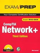
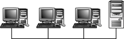
A LAN is confined to a single geographic location, such as a single building, office, or school. LANs are created with networking media that are very fast but that can cover a limited distance. Figure 1.1 shows an example of a LAN.
Figure 1.1 An example of a LAN.
Wide Area Network (WAN)
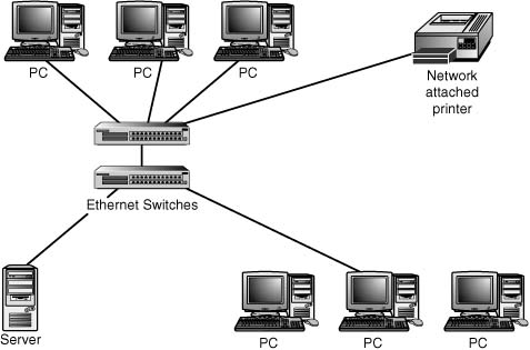
A WAN is a network that spans multiple geographic locations. WANs are generally slower than LANs and are considerably more expensive to run. WANs are all about data throughput, and the more you need, the more you spend. WANs connect LANs to create an internetwork. Figure 1.2 shows an example of a WAN.
Figure 1.2 An example of a WAN.
WANs often use different technologies from LANs. WAN technologies are discussed in Chapter 8, “Wide Area Networking.”
Exam Alert
LAN/WAN technologies An understanding of the technologies used in both LANs and WANs is required for the Network+ test. These technologies are covered in detail throughout the rest of this book.
Note
When does a LAN become a WAN? Technically, a LAN never becomes a WAN. If the definitions of LAN and WAN were taken literally and applied to a working model that had three connected sites, the portions of the network confined within each site would be LANs, and the network elements connecting the sites would be called the WAN. Another distinction between a LAN and a WAN is that, in order to function, a WAN relies on an Internet service provider (ISP) or telecommunications company (Telco) to provide a link. The IS link can be a variety of technologies including digital (T1 lines), ISDN lines, and even analog lines. Avoid the temptation to refer to the entire internetwork as a WAN, because WANs and LANs employ different technologies.
Metropolitan Area Networks (MAN)
A MAN is confined to a certain geographic area, such as a university campus or a city. No formal guidelines dictate the differences between a MAN and a WAN; technically, a MAN is a WAN. Perhaps for this reason, the term MAN is used less frequently than WAN. If any distinction exists, it’s that a MAN is smaller than a WAN. A MAN is almost always bigger than a LAN and usually smaller than or equal to a WAN. MANs utilize an ISP or Telco provider.
Note
CANs You might hear the term campus area network (CAN) in discussions of network layouts. A CAN is a network that spans a defined single location (such as an office complex with multiple buildings or a college campus) but is not large enough to be considered a WAN.
Personal Area Networks (PAN)
A personal area network (PAN) is a small network design typically associated with a single person. A common implementation of a PAN is using wireless technologies. Wireless developments have introduced a new term—wireless personal area networks (WPAN). WPAN refers to the technologies involved in connecting devices in close proximity to exchange data or resources. An example might be connecting a laptop with a PDA to synchronize an address book. Because of their small size and the nature of the data exchange, WPAN devices lend themselves well to ad hoc wireless networking. Ad hoc wireless networks have devices, such as wireless network interface cards, that connect to each other directly and not through a wireless access point. Ad hoc wireless networks are discussed later in this chapter.
Because of the close proximity of WPAN networking, short-range wireless technologies are typically used. This includes Bluetooth and infrared. The key WPAN technology supported in Windows XP Professional, for example, is Infrared Data Association (IrDA).
Now that you understand the purpose and function of networks and how networks are classified based on size, in the following section you look at the specific types of computer networks, including peer-to-peer, client/server, virtual private, and virtual local area networks.
Peer-to-Peer Versus Client/Server Networks
Wired networks use two basic models: peer-to-peer and client/server. The model used by an organization depends on the role of the network and what the users require from it. You will probably encounter both network models; therefore, you need to understand how these models work as well as their strengths and weaknesses.
The Peer-to-Peer Networking Model
Peer-to-peer networking, sometimes referred to as a workgroup, is a low-cost, easily implemented network solution generally used in small network environments that need to share a few files and maybe some hardware, such as printers. As its name suggests, on a peer-to-peer network all systems are equal, or peers. Each system can share hardware or files and access the same resources on other systems.
Note
Peer-to-peer home networks Peer-to-peer networks are often seen in residential settings, where home computers are linked together to share an Internet connection, printers, or files. All popular workstation PC operating systems offer peer-to-peer network functionality.
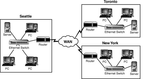
A peer-to-peer network offers no centralized data storage or centralized control over the sharing of files or resources. In a sense, everyone on a peer-to-peer network is a network administrator and can share resources as they see fit. They have the option to grant all users on the network complete access to their computers, including printers and files, or they can choose not to share anything. Figure 1.3 shows an example of a peer-to-peer network.
Figure 1.3 An example of a peer-to-peer network.
The peer-to-peer model works well on networks that have 10 or fewer computers, but as a network grows, it becomes more complicated. Peer-to-peer networking is often referred to as decentralized networking because the network files, data, and administration are not handled from a central location. This arrangement can lead to huge problems, especially in large networks. For example, locating specific files can become difficult because the files might be on multiple computers. Data backup cannot be performed from a central location; each computer must be backed up individually. Decentralized networking can also be difficult in terms of network security because security is controlled by individual computer users instead of being administered from a central location. This decentralized security model requires that each user have a user ID and password defined on each and every system that user will access. With no way of synchronizing passwords between the systems, this can quickly become a problem. Many users have problems remembering just one or two passwords, let alone a dozen.
Given the complexity and drawbacks of using peer-to-peer networking, you might wonder why anyone would use it. Many small companies begin with a peer-to-peer network because it’s the easiest and least expensive type to install. After the networks grow too big, they switch to the client/server model, which is discussed in the next section.
Note
Peer-to-peer network size A peer-to-peer network can link an unlimited number of PCs; no standards define a maximum. The only limits are the practicality of managing multiple systems in a peer-to-peer model and the restrictions of the operating system being used on the workstations.
Advantages of Peer-to-Peer Networks
The following are two of the advantages of using the peer-to-peer networking model:
• Cost—Because peer-to-peer networking does not require a dedicated server, such networks are very cost-effective. This makes them an attractive option in environments where money is tight.
• Ease of installation—The built-in support for peer-to-peer networking in modern operating systems makes installing and configuring a peer-to-peer network a straightforward process.
• Maintenance—A small peer-to-peer network is easy to maintain and does not require specialized staff or training. This makes the peer-to-peer network design cost-effective.
Disadvantages of Peer-to-Peer Networks
The following are some of the disadvantages of using the peer-to-peer networking model:
• Security—In a decentralized model, a networkwide security policy cannot be enforced from a server; rather, security needs to be applied to each computer and resource individually.
• Data backup—Because files and data are located on individual computers, each system must have its data backed up individually.
• Resource access—In a decentralized approach, it can be difficult to locate resources on the network. Printers and files may be distributed among numerous computer systems.
• Limited numbers of computers—Peer-to-peer networking is effective only on small networks (fewer than 10 computers).
As you can see, the disadvantages of peer-to-peer networking outweigh the advantages. Therefore, client/server networks are far more popular in corporate or business environments than peer-to-peer networks are.
The Client/Server Networking Model
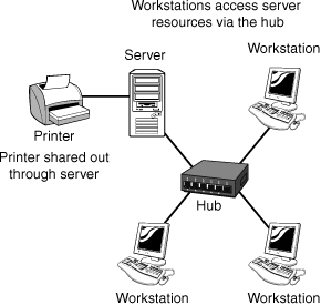
Client/server networking—or server-based networking, as it is commonly called—is the network model you are most likely to see in the corporate world. The server-based network model is scalable, allowing additional computers or other networked devices to be added with little difficulty. Perhaps the greatest benefit of this model is that it allows for centralized management of all network services, security, and streamlined backup procedures. Figure 1.4 shows an example of a client/server network.
Figure 1.4 An example of a client/server network.
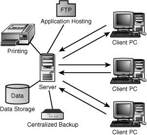
As you may have gathered, two types of computers are required for the server-based model: the client and the server. Figure 1.5 shows the relationship between client and server computers. These two computer systems are often very different from each other, and each plays a unique role on a network.
Figure 1.5 The relationship between client and server computers.
Servers
Servers are the workhorses of the network. They spend their time responding to the numerous requests that come from client computers, such as requests for files, network authentication, and access to shared hardware resources. Network administration—including network security, backups, and network monitoring—is done from the server.
To perform their functions, server computers require additional resources and computing power. Server systems often use specialized hardware and software in fault-tolerant configurations to ensure that they remain operational. When a server fails and goes offline, it cannot respond to requests from client systems, and its functions are unavailable. This situation can be frustrating for users and costly for an organization.
In addition to requiring specific hardware, servers also require a network operating system. A network operating system stands above ordinary desktop operating systems; it has unique features and functions that allow an administrator to manage, monitor, and administer the data and resources of the server as well as the users who connect to it. In addition, network operating systems are designed to be resilient in case of the kind of downtime discussed earlier.
A network may have a single server that offers more than one network service or hundreds of servers, each performing a dedicated task. For example, one server might be used only to authenticate users, and another might be used to store an applications database. Some of the most common roles for dedicated servers include acting as file and print servers, application servers, web servers, database servers, firewall servers, and proxy servers.
Client Computers
Client computers are the other half of the client/server model. Client computers connect to the network and access the resources of the server. Software is needed to allow the client to connect to the network, although the need for networking has become so fundamental that the client software functionality is now built in to desktop operating systems.
Advantages of Client/Server Networking
The following are some of the advantages of the client/server networking model:
• Centralized management and security—The capability to manage the network from a single location is the biggest advantage of the client/server model. From a server, you can perform backups of all data, share resources and control access to those resources, manage user accounts, and monitor network activity.
• Scalability—In a server-based network, administrators can easily add computers and devices. In addition, the network is not restricted to a small number of computers. In a client/server network, the number of clients is limited by factors such as licensing and network capacity rather than by the operating system’s capability to support them.
• Simplified backups—On server-based networks, files and folders typically reside in a single location or a small number of locations and are therefore easier to back up than the files on a peer-to-peer network. Scheduling backups to occur at regular intervals is simple.
Disadvantages of Client/Server Networking
The following are some of the disadvantages of the client/server networking model:
• High cost—A server-based network requires additional hardware and software, so it can be a costly venture. The costs of the client/server model include the costs of the network operating system and at least one server system, replete with specialized server hardware. Also, because the client/server model can support far more systems than the peer-to-peer model, networking devices such as hubs, routers, and switches are often needed.
• Administration requirements—Client/server networks require additional administrative skills over those required on a peer-to-peer network. In particular, the technical capabilities of the administrator need to be greater. Organizations that use the server-based model often need technically skilled people to manage and maintain the network and the servers.
• Single points of failure—In a client/server model, the client systems depend on servers to provide network services. If the server fails, the clients can’t access the services that reside on the server. Great effort and expense are needed to ensure the high availability of network servers.
Given the limitations of the peer-to-peer network design, such networks are used in only a few situations. On the other hand, the client/server networking model is versatile, and its shortcomings are overshadowed by its capabilities and advantages. You will spend most of your time working with server-based networks of all shapes and sizes.
Note
Hybrid networks The distinction between networks that use a peer-to-peer design and those that use a client/server design is not always clear. Today’s operating systems let client computers share resources with other systems in a peer-to-peer configuration and also be connected to a server. Such an arrangement is sometimes referred to as a hybrid network. Although this model takes advantage of the benefits of both network models, it is also susceptible to their combined shortcomings.
Distributed and Centralized Computing
Although they’re less of an issue than in the past, you need to be familiar with two important networking concepts: distributed and centralized computing. These concepts are not directly related to the server-based/peer-to-peer discussion, although by definition a peer-to-peer and server-based network model are examples of a distributed computing model.
The terms distributed and centralized computing describe the location on a network where the processing takes place. In an environment such as a mainframe, the processing is performed on a centralized system that also stores all the data. In such a model, no data processing or data storage occurs on the client terminal. In contrast, in a distributed processing environment, processing is performed in more than one place. If a network has servers and workstations, processing can take place on the server or on the client.
It is relatively unusual for a company to have just a centralized computing environment. A company is far more likely to have a server-based network, which would fall under the banner of distributed computing, and perhaps a mainframe that is accessed from the same PCs as the server-based network, which would fall under the banner of centralized computing. A good example of such an environment might be a company that books hotel reservations for customers, in which the booking system is held on a mainframe, but the email system used to correspond with clients is held on a PC-based server and accessed through client software on the PCs.
Virtual Private Networks (VPN)
In the mid-1990s, Microsoft, IBM, and Cisco began working on a technology called tunneling. By 1996, more companies had become interested and involved in the work, and from their efforts virtual private networks (VPN) became one of the most popular methods of remote access. But before you can understand why VPNs became so popular, you must first know a bit more about them.
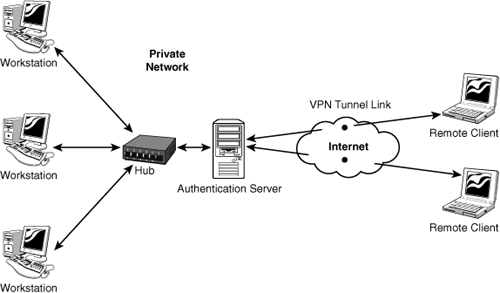
Essentially, a VPN extends a LAN by establishing a remote connection using a public network such as the Internet. A VPN provides a secure point-to-point dedicated link between two points over a public IP network. Figure 1.6 shows how a VPN enables remote access for a remote client to a private network.
Figure 1.6 Remote access using a VPN.
For many companies, the VPN link provides the perfect method to expand their networking capabilities and reduce their costs. By using the public network (Internet), a company does not need to rely on expensive private leased lines to establish and maintain the remote connection. Using the Internet to facilitate the remote connection, the VPN enables network connectivity over a possibly long physical distance. In this respect, a VPN is a form of WAN.
Note
Using the VPN Many companies use a VPN to provide a cost-effective method of establishing a connection between remote clients and a private network. VPN can also be used for connecting one private LAN with another, known as LAN-to-LAN internetworking. For security reasons, it is possible to use a VPN to provide controlled access within an intranet.
Components of the VPN Connection
A VPN allows anyone with an Internet connection to use the infrastructure of the public network to connect to the main network and access resources as if the user were logged on to the network locally. It also allows two networks to be connected to each other securely.
Many elements are involved in establishing a VPN connection, including the following:
• A VPN client—The VPN client is the computer that initiates the connection to the VPN server. Referring back to Figure 1.6, you’ll notice that the VPN clients are the laptop computer systems labeled remote clients.
• A VPN server—The VPN server authenticates connections from VPN clients.
• An access method—As mentioned, a VPN is most often established over a public network such as the Internet; however, some VPN implementations use a private intranet. The network used must be IP based.
• VPN protocols—Protocols are required to establish, manage, and secure the data over the VPN connection. The Point-to-Point Tunneling Protocol (PPTP) and the Layer 2 Tunneling Protocol (L2TP) are commonly associated with VPN connections. These protocols, and their supporting protocols, enable authentication and encryption in VPNs. Authentication allows VPN clients and servers to correctly establish the identity of people on the network. Encryption allows potentially sensitive data to be guarded from the general public.
VPNs have become popular because they allow the public Internet to be safely utilized as a WAN connectivity solution.
Exam Alert
VPN connections VPNs support analog modems, Integrated Services Digital Network (ISDN) wireless connections, and dedicated broadband connections such as cable and Digital Subscriber Line (DSL). You should remember this for the exam.
VPN Pros and Cons
As with any technology, pros and cons exist. Fortunately with VPN technology, these are clear cut, and even the cons typically do not prevent an organization from using VPNs in their networks. There are several benefits to using a VPN in your network, but like any other technology there are some drawbacks. The following list highlights the good and the bad of VPNs:
• Reduced cost—By using the public network, no need exists to rent dedicated lines between remote clients and a private network. Additionally, a VPN also can replace remote access servers and long-distance dial-up network connections commonly used in the past by business travelers needing to access their company intranet. This eliminates long-distance phone charges.
• Network scalability—The cost to an organization of building a dedicated private network may be reasonable at first but increases exponentially as the organization grows. The Internet allows an organization to grow its remote client base without having to increase or modify an internal network infrastructure.
• Reduced support—Using the Internet, it is not necessary for organizations to employ support personal to manage a VPN infrastructure.
• Simplified—With a VPN network, adding and removing clients is a straightforward process. Authentication work is managed from the VPN authentication server, and client systems can be easily configured for automatic VPN access.
Disadvantages of using a VPN include the following:
• Security—Using a VPN, data is sent over a public network and therefore there is a risk of data being captured and compromised. This risk is minimized as much as possible with the use of various security protocols. VPN administrators will need an understanding of data security over public networks to ensure that data is not tampered with or stolen.
• Reliability—The reliability of the VPN communication is dependant upon the public network and is not under an organization’s direct control. Instead, the solution relies on an ISP and their quality of service.
Virtual Local Area Network (VLAN)
The word virtual is used often—perhaps too often—in the computing world. In the case of virtual LANs (VLAN), the word virtual does little to help explain the technology. Perhaps a more descriptive name for the VLAN concept might have been segmented. For now at least, we use virtual.
Tip
802.1Q 802.1Q is the Institute of Electrical and Electronics Engineers (IEEE) specification developed to ensure interoperability of VLAN technologies from the various vendors.
VLANs are used for network segmentation, a strategy that significantly increases the performance capability of the network, removes potential performance bottlenecks, and can even increase network security. A VLAN is a group of connected computers that acts as if they are on their own network segments, even though they might not be. For instance, suppose that you work in a three-story building in which the advertising employees are spread over all three floors. A VLAN can let all the advertising personnel be combined and access network resources as if they were connected on the same segment. This virtual segment can be isolated from other network segments. In effect, it would appear to the advertising group that they were on a network by themselves.
Tip
VLANs VLANs enable you to create multiple broadcast domains on a single switch. In essence, this is the same as creating separate networks for each VLAN.
VLANs offer some clear advantages. Being able to create logical segmentation of a network gives administrators flexibility beyond the restrictions of the physical network design and cable infrastructure. VLANs allow for easier administration because the network can be divided into well-organized sections. Further, you can increase security by isolating certain network segments from others. For example, you can segment the marketing personnel from finance or the administrators from the students. VLANs can ease the burden on overworked routers and reduce broadcast storms. The following list summarizes the benefits of VLANs:
• Increased security—By creating logical (virtual) boundaries, network segments can be isolated.
• Increased performance—By reducing broadcast traffic throughout the network, VLANs free up bandwidth.
• Organization—Network users and resources that are linked and communicate frequently can be grouped together in a VLAN.
• Simplified administration—With a VLAN the network administrator’s job is easier when moving users between LAN segments, recabling, addressing new stations, and reconfiguring hubs and routers.
VLAN Membership
You can use several methods to determine VLAN membership or determine how devices are assigned to a specific VLAN. The methods include protocol-based VLANs, port-based VLANs, and MAC address-based VLANs, as described in the following sections.
Protocol-Based VLANs
With protocol-based VLAN membership, computers are assigned to VLANs by using the protocol that is in use and the Layer 3 address. For example, it allows the IP subnet to have its own VLAN.
When we say Layer 3 address, we are referring to one of the most important networking concepts, the Open Systems Interconnect (OSI) reference model. This conceptual model, created by the International Organization for Standardization (IOS) in 1978 and revised in 1984, describes a network architecture that allows data to be passed between computer systems. There are seven layers in total, which are discussed in detail in Chapter 9, “OSI Model.” In brief, Layer 3, known as the network layer, identifies the mechanisms by which data can be moved between two networks or systems. One mechanism is transport protocols, which in the case of TCP/IP is the IP protocol.
It is important to note that although VLAN membership may be based on Layer 3 information, this has nothing to do with routing or routing functions. The IP numbers are used only to determine the membership in a particular VLAN—not to determine routing.
Port-Based VLANs
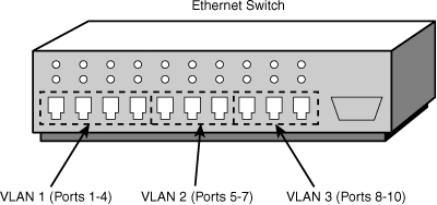
Port-based VLANs require that specific ports on a network switch be assigned to a VLAN. For example, ports 1 through 4 may be assigned to marketing, ports 5 through 7 may be assigned to sales, and so on. Using this method, a switch determines VLAN membership by taking note of the port used by a particular packet. Figure 1.7 shows how the ports on a server could be used for port-based VLAN membership.
Figure 1.7 Port-based VLAN membership.
MAC Address–Based VLANs
The Media Access Control (MAC) address is a unique 12-digit hexadecimal number that is stamped into every network interface card. Every device that will be used on a network has a unique address built in to it. It is hardwired and cannot be physically modified. As you may have guessed, the MAC address-based VLAN assigns membership according to the MAC address of the workstation. To do this, the switch must keep track of the MAC addresses that belong to each VLAN. The advantage of this method is that a workstation computer can be moved anywhere in an office without needing to be reconfigured; because the MAC address does not change, the workstation remains a member of a particular VLAN. Table 1.1 provides an example of the membership of a MAC address–based VLAN.
Table 1.1 MAC Address–Based VLANs

VLAN Segmentation
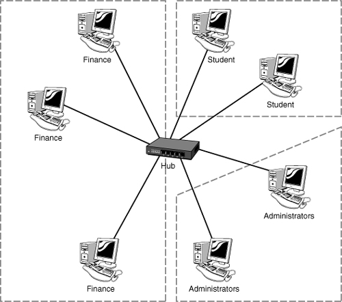
The capability to logically segment a LAN provides a new level of administrative flexibility, organization, and security. Whether the LAN is segmented using the protocol, MAC address, or port, the result is the same, the network is segmented. The segmentation is used for several reasons, including security, organization, and performance. To get a better idea of how this works, let’s look at a network without using a VLAN. Figure 1.8 shows this network design.
Figure 1.8 Network configuration without using a VLAN.

In Figure 1.8, all systems on the network can see each other. That is, the student computers can see both the administrator and finance computers. In terms of security, this is not a good arrangement. Figure 1.9, on the other hand, shows how this same network may look using a VLAN. Notice that the three network users are separated using the VLAN. To these users, the other networks are invisible.
Figure 1.9 Network configuration using VLAN.
LAN Topologies
The term network topology refers to the layout of a network. The type of topology affects what networking method is used, as well as what media types and network devices are required. Topologies are very important, and they serve as the foundation for the information you’ll learn in the following sections. You will likely be asked about topologies on the Network+ exam.
Before we look at the different types of topologies, we must first examine one of the most confusing networking principles: the difference between physical and logical topologies. Then we’ll examine the specific physical LAN topologies in use today: bus, star, ring, mesh, and wireless.
Physical and Logical Topologies
Network topologies can be defined on a physical level or on a logical level. The physical topology refers to how a network is physically constructed—that is, how it actually looks. The logical topology refers to how a network looks to the devices that use it—in other words, how it actually functions. In a number of commonly implemented network models, the physical topology differs from the logical topology. It can be difficult to appreciate what that means, so let’s use an example.
The most commonly implemented network model is a physical star/logical bus topology. In this configuration, computers are connected to a central device, called a hub or switch, which gives the network the appearance of a star (or a reasonable facsimile thereof). However, the devices attached to the star see the network as a linear bus topology and use the topology based on its logical characteristics.
Exam Alert
Network topologies Understanding network topologies and their characteristics is an objective for the Network+ exam. Therefore, you should make sure that you understand the concept of topologies. This includes both wired and wireless topologies.
Note
How did we get here? The physical/logical topology discussion can be confusing, so let’s examine its background. When networks were first created, they followed a simple path. For example, the first ethernet network was a physical and logical bus (single length of cable). As you will see in upcoming sections, however, this physical bus approach has a number of disadvantages; therefore, alternatives were sought. In this case, the solution was to move away from the single cable segment approach and instead use different types of cable on a physical star. The media access method and the networking system remained the same, however, resulting in a physical star/logical bus topology.
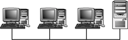
Bus Topology
The bus network topology is also known as a linear bus because the computers in such a network are linked together using a single cable called a trunk, or backbone. Computers are connected to this backbone as shown in Figure 1.10.
Figure 1.10 An example of the bus topology.
Exam Alert
Bus topology Be prepared to identify the bus topology on the Network+ exam.
The computers can be connected to the backbone by a cable, known as a drop cable, or, more commonly, directly to the backbone via T connectors. At each end of the cable, terminators prevent the signal from bouncing back down the cable. In addition, one end of the cable should be grounded. More information on the specific connectors and cables used in different network implementations is provided in Chapter 2, “Media and Connectors.”
Note
Ethernet standards The most common implementation of a linear bus is the Institute of Electrical and Electronics Engineers (IEEE) 802.3a standard, 10Base2, which is an ethernet standard. Ethernet standards are covered in Chapter 6, “Ethernet Networking Standards.”
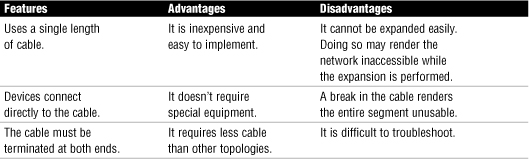
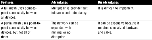
Bus topologies are easy and inexpensive to implement because a single-segment bus topology doesn’t require any special networking equipment. However, they are notoriously difficult to troubleshoot, and a single break in the network cable renders the entire segment useless. For this and a number other reasons, such as limited speed capacity, bus topologies have been largely replaced with the physical star topology. Table 1.2 lists the main features, advantages, and disadvantages of bus topologies.
Table 1.2 Features, Advantages, and Disadvantages of the Linear Bus Topology
Exam Alert
Bus topology advantages and disadvantages For the Network+ exam, make sure that you understand the advantages and disadvantages of the bus topology.
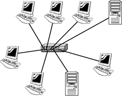
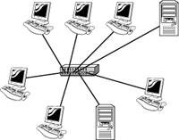
Star Topology
In a star topology, each device on the network connects to a centralized device via a separate cable. This arrangement creates a point-to-point network connection between the two devices and overall gives the appearance of a star. Figure 1.11 shows an example of the star topology.
Figure 1.11 An example of the star topology.
Exam Alert
Star topology Be prepared to identify the star topology on the Network+ exam.
Because each device must have its own cable, a star topology requires far more cable than other topologies, such as a physical linear bus. In addition, special equipment is required to create the star layout, adding to the cost of implementing a star topology. (Chapter 3, “Networking Components and Devices,” explains the function of network devices, such as hubs and switches, that are used in a star topology.)
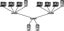
Multiple stars can be rearranged into a treelike structure known as a hierarchical star. The hierarchical star allows for high levels of flexibility and expandability. Depending on the networking equipment used, it also makes it possible to manage traffic and isolate high-traffic areas of the network. Figure 1.12 shows an example of a hierarchical star topology.
Figure 1.12 An example of the hierarchical star topology.
Exam Alert
Hierarchical star topology Be prepared to identify a hierarchical star topology on the Network+ exam.
One of the biggest advantages of the star topology is that computers can be connected to and disconnected from the network without affecting any other systems. Thus it’s easy to add systems to or remove systems from the network. In addition, the failure of a system or the cable it uses to attach likewise generally has no effect on other stations on the network. However, in the star topology, all devices on the network connect to a central device, and this central device creates a single point of failure on the network.
Note
The Ethernet 100Base-T Standard The most common implementation of the physical star topology is the Ethernet 100 Base-T standard.
The star topology is the most widely implemented network design in use today; you will definitely encounter it in the real world. Working with and troubleshooting a star topology can be tricky, however, and you need to know what to look for and where to look.
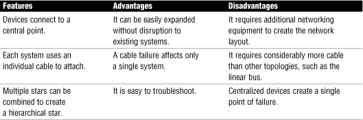
Table 1.3 provides the features, advantages, and disadvantages of the physical star topology.
Table 1.3 Features, Advantages, and Disadvantages of the Physical Star Topology
Tip
Star topology advantages and disadvantages For the Network+ exam, make sure that you understand the advantages and disadvantages of the star topology.
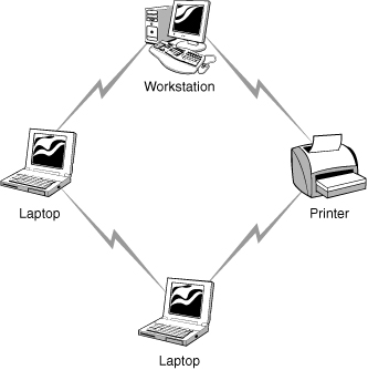
Ring Topology
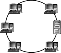
In the ring topology, the network layout forms a complete ring. Computers connect to the network cable directly or, far more commonly, through a specialized network device.
On a ring network, data travels in one direction, passing from one computer to the next until it reaches the intended destination. Figure 1.13 shows an example of the ring topology.
Figure 1.13 An example of the ring topology.
Exam Alert
Ring topology Be prepared to identify the ring topology on the Network+ exam.
Ring topologies are more difficult to install and configure than other topologies because breaking the loop disrupts the entire network. Even if network devices are used to create the ring, the ring must still be broken if a fault occurs or the network needs to be expanded. To negate the problem of a broken ring making the network unavailable, you can configure dual rings so that one ring can be used if the other fails.
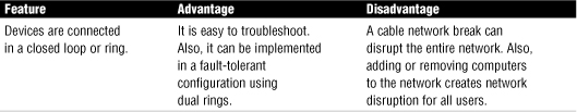
Ring topologies are relatively uncommon; the physical star layout is by far the most popular topology. For this reason, you are unlikely to actually install a ring topology. Table 1.4 shows the features, advantages, and disadvantages of the ring topology.
Table 1.4 Features, Advantages, and Disadvantages of the Ring Topology
Exam Alert
Ring topology advantages and disadvantages For the Network+ exam, make sure that you understand the advantages and disadvantages of the ring topology.
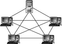
Wired Mesh Topology
The mesh network topology is all about link redundancy. A mesh network uses multiple connections between network devices to ensure that if one link should fail, an alternate path exists for data to travel and reach its destination. The goal of the mesh network is to provide maximum reliability and redundancy for the network but this ability comes at a price. Establishing these redundant links can be costly in terms of wiring, support, and maintenance.
There are essentially two types of mesh topologies: full and partial. A full wired mesh topology interconnects every node with every other node on the network. As you might imagine, the complexity and cost of this topology can be significant. Full mesh is usually reserved for backbone networks.
A partial wired mesh interconnects some or most nodes, but others nodes do not have redundant links. Typically, mission critical servers and systems are fully meshed, whereas some other less-critical systems are left to traditional single nonredundant links. Partial mesh topology is commonly found in peripheral networks connected to a full meshed backbone.
Figure 1.14 shows an example of the mesh topology.
Figure 1.14 An example of the full mesh topology.
Note
Fault tolerance The mesh layout is the most fault tolerant of all the network topologies. Redundant links exist between all nodes, and the failure of a single link does not affect the overall functionality of the network.
Given the relative ease with which the other topologies can be created and the complexity of the mesh layout, you should not be surprised to learn that wired networks using the mesh layout are few and far between. In fact, you are unlikely to see a mesh layout in a LAN setting. The mesh topology is sometimes adopted in WAN configurations that require direct connections between each and every geographic site.
Table 1.5 lists the features, advantages, and disadvantages of the mesh topology.
Table 1.5 Features, Advantages, and Disadvantages of the Mesh Topology
Exam Alert
Mesh topology advantages and disadvantages For the Network+ exam, make sure that you understand the advantages and disadvantages of the mesh topology.
Wireless Network Topologies
The widespread interest in networks without wires and the push toward obtaining “anywhere, anytime” Internet access has encouraged rapid growth in wireless standards and related technologies. The IEEE 802.11 wireless standards in particular have experienced considerable success. Several wireless standards fall under the 802.11 banner, each with its own speeds, radio frequencies, and transmission ranges. These standards create the possibility for wireless local area networking (WLAN) and put the possibility of complete mobile computing within reach.
When working with wireless technologies, you need to be aware of several types of topologies. These include the infrastructure, or managed, wireless topology, the ad-hoc, or unmanaged, wireless topology, point-to-point wireless design, point-to-multipoint, mesh wireless, and hybrid topologies.
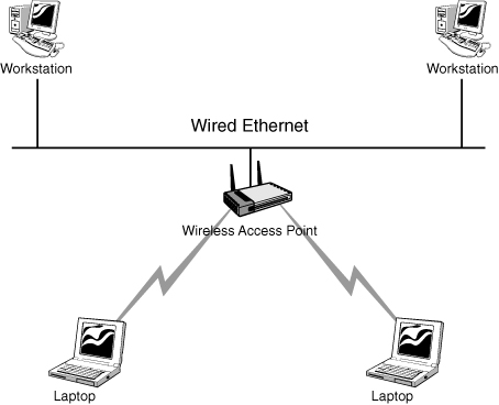
Infrastructure Wireless Topology
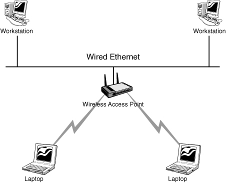
The infrastructure wireless topology is commonly used to extend a wired LAN to include wireless devices. Wireless devices communicate with the wired LAN through a base station known as an access point (AP). The AP forms a bridge between a wireless and wired LAN, and all transmissions between wireless stations or between a system and a wired network client go through the AP. APs are not mobile and have to stay connected to the wired network; therefore, they become part of the wired network infrastructure, thus the name. In infrastructure wireless networks, several access points may provide wireless coverage for a large area, or only a single access point may provide coverage for a small area, such as a single home or small building. Figure 1.15 shows an example of an infrastructure wireless network using a single AP.
Figure 1.15 Wireless infrastructure topology.
Note
Wireless BSS and ESS In the wireless infrastructure mode, the wireless network consists of at least one AP connected to the wired network infrastructure and a set of wireless end stations, as shown in Figure 1.15. This configuration is referred to as a basic service set (BSS).
In an extended service set (ESS) two or more BSSs combine to form a single subnetwork. Traffic is forwarded from one BSS to another to smooth the progress of movement.
Ad Hoc Wireless Networking
In a wireless ad hoc topology, devices communicate directly between themselves without using an access point. This peer-to-peer network design is commonly used to connect a small number of computers or wireless devices. For example, an ad hoc wireless network may be set up temporarily between laptops in a boardroom or to connect to systems in a home instead of a wired solution. The ad hoc wireless design provides a quick method to share files and resources between a small number of systems. Figure 1.16 shows an example of an ad hoc network design.
Figure 1.16 An ad hoc wireless topology.
Exam Alert
Ad hoc wireless topology The ad hoc, or unmanaged, network design does not use an AP. All wireless devices connect directly to each other.
Point-to-Point, Point-to–Multipoint, and Mesh-Wireless Topology
When setting up a wireless network, you can choose from several other topologies. These include the point-to-point, point-to–multipoint, and the wireless-mesh configurations.
Point-to-Point Networks
As the name suggests, in a point-to-point (PtP) wireless configuration, the communication link travels from one node directly to one other node. Wireless point-to-point systems are often used in wireless backbone systems, such as microwave relay communications, or as a replacement for a single wired communication cable. Figure 1.17 shows a point-to-point wireless configuration.
Figure 1.17 A point-to-point wireless topology.
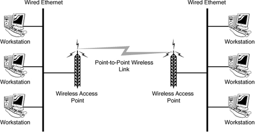
As seen in Figure 1.17, the point-to-point wireless link connects two remote locations. Not having to run cable, such as fiber, makes it an economical way to provide a communication link. However, in a typical point-to-point wireless configuration, no redundancy exists. This means if the wireless link should fail, communication between the locations will not be available.
The point-to-point link is often used for organizations that need a direct link between two remote office buildings. These point-to-point wireless connections are typically easy to install and require no external outdoor casing, cables, and other accessories. Because there is no need for the cabling infrastructure, a point-to-point wireless solution is a cost-effective method for connecting two remote locations.
Point-to-Multipoint
A point-to-multipoint (PtMP) wireless connection is designed to link multiple wired networks. Signals in point-to-multipoint networks travel from a central node, such as a base station of a cellular system, an access point of a WLAN, or a satellite. The function of the multipoint wireless topology is to interconnect multiple locations enabling them to access and share resources. Multipoint networks use a base station as the “hub” and client networks as the connection points communicating with the base station. These point-to-multipoint networks are used in wireless Internet service providers (WISP), large corporate campuses, interconnected branch offices, and more.
The reliability of the PtMP network topology relies on the quality of the central node and each connecting node. The location of the central node is very important to ensure range and strength of the wireless signal.
Mesh Networks
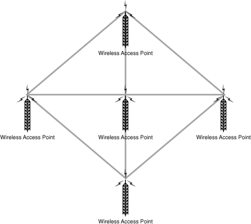
Mesh networks are common in the wireless networking world. In the wireless mesh network, as with the wired mesh, each network node is interconnected to other nodes on the network. With a wired mesh, the wireless signal starts at a wireless base station (access point) attached to a wired network. A wireless mesh network extends the transmission distance by relaying the signal from one computer to another. Unlike the wired mesh where a complex and expensive collection of physical cables are required to create the mesh, the wireless mesh is cheap to implement. Figure 1.18 shows an example of a wireless mesh network.
Figure 1.18 Wireless mesh topology.
Exam Alert
Wireless mesh A wireless mesh network is created through the connection of wireless APs installed at each network user’s locale. Data signals in a wireless mesh rely on all nodes to propagate signals. Wireless mesh networks can be identified by the interconnecting signals between each node.
The wireless mesh network has several key advantages. Because a wireless mesh network is interconnected with one or more nodes on the network, multiple paths exist for data to travel to reach its destination. When a new node is added, it provides new paths for other nodes, which in turn improves network performance and decreases congestion. Advantages of the wireless mesh include the following:
• Self-Healing—Wireless mesh networks are known as self–healing, which refers to the networks’ ability to adapt to network failure and function even if a node is moved from one location to another. Self-healing in a wireless mesh environment is possible because of the interconnected links between devices and because of the actual wireless media.
• Scalable—Wireless mesh networks are highly scalable. Using wireless, it is possible to add new systems to the network without the need for expensive cables.
• Reliability—Of all network topologies, the mesh network provides the greatest reliability. The redundant number of paths for the data to travel ensure that data can reach its destination.
• Cost—One of the disadvantages of the wired mesh is the cost associated with running the cabling and the support costs of such a complex network. Wireless mesh networks are essentially self-configuring and do not have the cabling requirements. Therefore, systems can be added, removed, and relocated with little cost or disruption to the network.
Hybrid Topologies
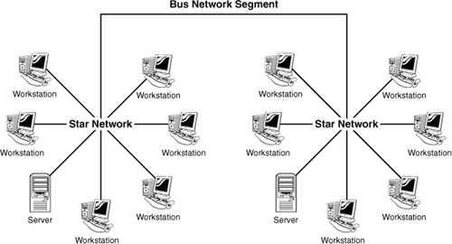
As you might expect, topology designs are not black and white. Many of the topologies we see in large networking environments are a hybrid of physical topologies. An example of a hybrid topology is the star-bus, which is a combination of the star topology and the bus topology. Figure 1.19 shows how this may look in a network implementation.
Figure 1.19 A star-bus topology.
Another example of a hybrid topology is the star-wired ring topology, which is the combination of the physical star topology and the physical ring topology.
Note
Another meaning The term hybrid topology also can refer to the combination of wireless and wired networks. For the Network+ exam, however, the term hybrid most likely refers to the combination of physical networks.
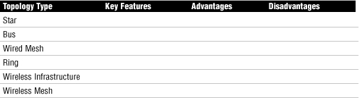
Challenge
You have been asked to recommend a topology for a new network. You have been asked to consider all options and prepare a document that shows how they compare. To complete your task, you decide to create a chart showing the advantages and disadvantages of the various network topologies. For this exercise, complete the following chart:
Summary
This chapter provides an overview of the functions and purposes of computer networks. Key among the functions of the network are increased communication, both in real-time and via email, sharing of hardware between multiple users, reduction in overall cost and support of multiple devices, and the capability to share files.
Two network models are identified in this chapter: peer-to-peer networking and client/server networking. Peer-to-peer networking is restricted to networks with few users and does not use a centralized server. Peer-to-peer networks are most commonly seen in home network environments and in small offices.
The client/server model is more common and familiar than the peer-to-peer model, especially in larger networks. The client/server model uses a dedicated server and offers many advantages over the peer-to-peer network model. Perhaps most notable of these advantages is the capability to centrally manage the network, although the cost and administration requirements are higher than those of peer-to-peer networks.
Two other network models discussed were VPNs and VLANs. VPNs provide a means to securely connect remote users to a network. VPNs use a variety of protocols to make and secure the connection. VLANs provide a way to segregate a network. Three ways that a VLAN does this are port-based VLANs, protocol-based VLANs, and MAC-based VLANs.
Networks have both physical and logical topologies. The physical topology refers to the way the network is physically laid out, including media, computers, and other networking devices such as hubs or switches. The logical topology refers to how data is transmitted around the network. Common network topologies include star, ring, bus, and mesh. Each of these topologies offers distinct advantages and disadvantages and various levels of fault tolerance.
Wireless networks are typically implemented using ad hoc or infrastructure network design. Wireless topologies include point-to-point, point-to–multipoint, and wireless-mesh design.
Key Terms
• Star
• Mesh
• Bus
• Ring
• LAN
• WAN
• PAN
• MAN
• Hybrid
• Topology
• VPN
• VLAN
Apply Your Knowledge
Exercise
1.1 Designing a Wireless Network
You have been asked to extend your company’s wired network using wireless technology. You need to provide network diagrams of the proposed wireless network. Diagrams should include a point-to-multipoint wireless topology and a wireless mesh topology.
Estimated time: 10 minutes
Exam Questions
1. Which of the following is a disadvantage of the physical bus topology?
![]() A. Has complex cabling requirements
A. Has complex cabling requirements
![]() B. Is prone to cable faults
B. Is prone to cable faults
![]() C. Requires a dedicated server
C. Requires a dedicated server
![]() D. Requires a dedicated hub
D. Requires a dedicated hub
2. Which of the following are valid ways to assign computers to a VLAN? (Choose the three best answers.)
![]() A. Protocol assignment
A. Protocol assignment
![]() B. Port-based assignment
B. Port-based assignment
![]() C. NetBIOS computer name
C. NetBIOS computer name
![]() D. MAC address
D. MAC address
3. Which of the following statements best describes a VPN?
![]() A. It is any protocol that allows remote clients to log in to a server over a network such as the Internet.
A. It is any protocol that allows remote clients to log in to a server over a network such as the Internet.
![]() B. It provides a system whereby only screen display and keyboard and mouse input travel across the link.
B. It provides a system whereby only screen display and keyboard and mouse input travel across the link.
![]() C. It is a secure communication channel across a public network such as the Internet.
C. It is a secure communication channel across a public network such as the Internet.
![]() D. It is a protocol used for encryption of user IDs and passwords.
D. It is a protocol used for encryption of user IDs and passwords.
4. Which of the following topologies offers the greatest level of redundancy?
![]() A. Mesh
A. Mesh
![]() B. Star
B. Star
![]() C. Bus
C. Bus
![]() D. Ring
D. Ring
5. You are the administrator for a local company. Recently a second branch of the company has opened across town. You need to connect the two networks in a cost-effective manner. Which of the following solutions could you use?
![]() A. VLAN
A. VLAN
![]() B. Star
B. Star
![]() C. VPN
C. VPN
![]() D. VWAN
D. VWAN
6. Which of the following is required to establish a VPN connection? (Choose all correct answers.)
![]() A. VPN server
A. VPN server
![]() B. VPN client
B. VPN client
![]() C. VPN protocols
C. VPN protocols
![]() D. VPN MAC identification
D. VPN MAC identification
7. You have just been hired as the administrator for a large corporation. The network connects two star network segments with a bus network. Which of the following network types is being used?
![]() A. Bus
A. Bus
![]() B. Star bus
B. Star bus
![]() C. Logical bus ring
C. Logical bus ring
![]() D. Mesh bus
D. Mesh bus
8. Which network topology is represented in the following diagram?
![]() A. Bus
A. Bus
![]() B. Star
B. Star
![]() C. Logical ring
C. Logical ring
![]() D. Mesh
D. Mesh
9. You have recently added several wireless clients to your company’s network. Each client will access the network through a wireless access point. Which of the following topologies are you using?
![]() A. Wireless token ring
A. Wireless token ring
![]() B. Wireless mesh topology
B. Wireless mesh topology
![]() C. Infrastructure
C. Infrastructure
![]() D. Ad hoc
D. Ad hoc
10. Which of the following topologies has a single connection between each node on the network and a centralized device?
![]() A. Ring
A. Ring
![]() B. Mesh
B. Mesh
![]() C. Star
C. Star
![]() D. Bus
D. Bus
11. You have been asked to connect two office locations together. A wireless link has been specified. Which of the following strategies would you use to connect the two offices?
![]() A. Point to point
A. Point to point
![]() B. Wireless mesh
B. Wireless mesh
![]() C. PtMP
C. PtMP
![]() D. Star-bus hybrid
D. Star-bus hybrid
12. Which topology is represented in the following diagram?
![]() A. Star topology
A. Star topology
![]() B. Star bus
B. Star bus
![]() C. Ad hoc
C. Ad hoc
![]() D. Infrastructure
D. Infrastructure
13. What is the name for a network that connects two geographic locations?
![]() A. PAN
A. PAN
![]() B. LAN
B. LAN
![]() C. DAN
C. DAN
![]() D. WAN
D. WAN
14. Which network topology is represented in the following diagram?
![]() A. Bus
A. Bus
![]() B. Star
B. Star
![]() C. Mesh
C. Mesh
![]() D. Ring
D. Ring

15. Which of the following is a feature of the physical star topology?
![]() A. It requires less cable than other physical topologies.
A. It requires less cable than other physical topologies.
![]() B. The network is very easy to expand.
B. The network is very easy to expand.
![]() C. Apart from the cable and connectors, no other equipment is required to create the network.
C. Apart from the cable and connectors, no other equipment is required to create the network.
![]() D. There is no single point of failure.
D. There is no single point of failure.
16. The 802.11 standard describes what kind of network?
![]() A. Wired mesh
A. Wired mesh
![]() B. Contention
B. Contention
![]() C. Wireless
C. Wireless
![]() D. Star bus
D. Star bus
17. A mainframe is an example of what computing model?
![]() A. Segregated
A. Segregated
![]() B. Distributed
B. Distributed
![]() C. Centralized
C. Centralized
![]() D. Decentralized
D. Decentralized
18. Which of the following network topologies offers the greatest level of redundancy but the highest implementation cost?
![]() A. Wireless mesh
A. Wireless mesh
![]() B. Wired mesh
B. Wired mesh
![]() C. Hybrid star
C. Hybrid star
![]() D. Bus network
D. Bus network
19. Which network topology is represented in the following diagram?
![]() A. Star
A. Star
![]() B. Bus
B. Bus
![]() C. Mesh
C. Mesh
![]() D. Ring
D. Ring
20. Which of the following technologies are used for network segmentation?
![]() A. VLAN
A. VLAN
![]() B. VPN
B. VPN
![]() C. Hybrids
C. Hybrids
![]() D. PtMP
D. PtMP
Answers to Exam Questions
1. B. One of the disadvantages of the physical bus topology is that it’s prone to cable faults. In addition, a fault on the cable can render the entire network unusable. The advantages of the physical bus topology are that the cabling is simple, and no additional network hardware is required to create the network. For more information, see the section “Bus Topology” in this chapter.
2. A, B, D. VLANs can be created by using protocol assignments, by defining the ports on a device as belonging to a VLAN, or by using MAC addresses. VLANs cannot be created by using the NetBIOS computer name. For more information, see the section “Virtual Local Area Network (VLAN)” in this chapter.
3. C. A VPN provides a secure communication path between devices over a public network such as the Internet. None of the other answers describes a VPN. For more information, see the section “Virtual Private Networks (VPN) in this chapter.
4. A. In a mesh topology, each device is connected directly to every other device. If there is a break in the connection between two devices, alternate paths between the two systems are available. None of the other topologies provide this level of redundancy. For more information, see the section “LAN Topologies” in this chapter.
5. C. A VPN extends a local area network by establishing a remote connection using a public network such as the Internet. A VPN provides a point-to-point dedicated link between two points over a public IP network. The VPN link can be used to connect remote networks via the Internet. For more information, see the section “Virtual Private Networks (VPN)” in this chapter.
6. A, B, C. Many elements are involved in establishing a VPN connection. This includes the VPN client to initiate the session, the VPN server to answer the client requests, and the VPN protocols to secure and establish the connection. For more information on the components of the VPN connections, see the section “Virtual Private Networks (VPN)” in this chapter.
7. B. The star-bus topology is a combination of the star topology and the bus topology. The bus topology forms the connection between star networks. For more information on the star-bus topology, see the section “Hybrid Topologies” in this chapter.
8. A. The diagram shows the physical bus topology. None of the other answers are valid. For more information, see the section “LAN Topologies” in this chapter.
9. C. The infrastructure wireless topology is commonly used to extend a wired LAN to include wireless devices. Wireless devices communicate with the wired LAN through a base station known as an access point or Wireless Access Point. The AP forms a bridge between a wireless and wired LAN, and all transmissions between wireless stations or between a system and a wired network client go through the AP. For more information, see the section “Wireless Network Topologies” in this chapter.
10. C. A star topology is created when each node on the network is connected to a central device. None of the other answers are valid. For more information, see the section “LAN Topologies” in this chapter.
11. A. In a point-to-point (PtP) wireless configuration, the communication link travels from one node directly to one other node. Wireless point-to-point systems are often used in wireless backbone systems such as microwave relay communications, or as a replacement for a single wired communication cable. The point-to-point link can be used to connect two locations to share data and resources. For more information, see the section “Wireless Network Technologies” in this chapter.
12. D. The infrastructure wireless topology is commonly used to extend a wired LAN to include wireless devices. Wireless devices communicate with the wired LAN through a base station known as an access point or wireless access point. The AP forms a bridge between a wireless and wired LAN, and all transmissions between wireless stations or between a system and a wired network client go through the AP. For more information, see the section “Wireless Network Topologies” in this chapter.
13. D. The term WAN describes a network that spans more than one geographic location. The only other valid term for a type of network is LAN, but a LAN is a network confined to a single location. None of the other answers are recognized terms for describing a network. For more information, see the section “LANs, WANs, MANs, and PANs” in this chapter.
14. D. The diagram shows a physical ring topology. All the other answers are incorrect. For more information, see the section “LAN Topologies” in this chapter.
15. B. Physical star networks use centralized devices to connect nodes on the network. Because devices can be plugged and unplugged from these devices without affecting any other systems on the network, star configurations are easy to expand. The disadvantages of a physical star network are that they require more cable than other topologies, require additional networking equipment, and create a single point of failure. For more information, see the section “LAN Topologies” in this chapter.
16. C. The IEEE 802.11 standard defines wireless networking architectures. For more information, see the section “Wireless Network Topologies” in this chapter.
17. C. A mainframe is an example of a centralized computing model. All the other answers are incorrect. For more information, see the section “Peer-to-Peer Versus Client/Server Networks” in this chapter.
18. B. The wired mesh topology requires each computer on the network to be individually connected to every other device. This configuration provides maximum reliability and redundancy for the network. However, it is very costly to implement because of the multiple wiring requirements. For more information, see the section “LAN Topologies” in this chapter.
19. A. A star topology is shown in the diagram. All the other answers are incorrect. For more information, see the section “LAN Topologies” in this chapter.
20. A. VLANs are used for network segmentation, a strategy that significantly increases the performance capability of the network, removes potential performance bottlenecks, and can even increase network security. For more information, see the section “Virtual Local Area Network (VLAN)” in this chapter.
Suggested Readings and Resources
• Lowe, Doug. Networking All-in-One Desk Reference for Dummies, 3rd ed. Wiley Publishing, 2008.
• Comer, Douglas E. Computer Networks and Internets, 5th ed. Prentice Hall, 2008.
• TechEncyclopedia, http://www.techencyclopedia.com.
• Computer networking tutorials and advice, http://compnetworking.about.com.