
Chapter 2
The Open Systems Interconnection Specifications
THE FOLLOWING COMPTIA NETWORK+ EXAM OBJECTIVES ARE COVERED IN THIS CHAPTER:
- 5.0 Industry standards, practices, and network theory
- 5.1 Analyze a scenario and determine the corresponding OSI layer
- Layer 1 – Physical
- Layer 2 – Data link
- Layer 3 – Network
- Layer 4 – Transport
- Layer 5 – Session
- Layer 6 – Presentation
- Layer 7 – Application
- 5.2 Explain the basics of network theory and concepts
- Encapsulation/de-encapsulation
- Modulation techniques
- Multiplexing
- De-multiplexing
- Analog and digital techniques
- TDM

In this chapter, we're going to analyze the Open Systems Interconnection (OSI) model. I'll thoroughly describe each part to you in detail because it's imperative for you to grasp the OSI model's key concepts. Once solidly equipped with this vital foundation, you'll be set to move on and build your own, personal storehouse of networking knowledge.
The OSI model has seven hierarchical layers that were developed to enable different networks to communicate reliably between disparate systems.
Because this book is centering upon all things Network+, it's crucial for you to understand the OSI model as CompTIA sees it, so I'll present each of its seven layers in that light.
I'll also provide you with an introduction to encapsulation, which is the process of encoding data as it goes down the OSI stack. I'll finish this chapter by covering important modulation techniques.

To find up-to-the-minute updates for this chapter, please see www.lammle.com/forum or the book's website at http://sybextestbanks.wiley.com/
Internetworking Models
In the very first networks, the computers involved could communicate only with other computers made by the same manufacturer. For example, companies ran either a complete DECnet solution or an IBM solution—not both together. In the late 1970s, the Open Systems Interconnection (OSI) reference model was created by the International Organization for Standardization (ISO) to break through this barrier.
The OSI model was meant to help vendors create interoperable network devices and software in the form of protocols, or standards, so that different vendors’ networks could become compatible and work together. Like world peace, it'll probably never happen completely, but it's still a great goal.
The OSI model is the primary architectural model for networks. It describes how data and network information are communicated from an application on one computer through the network media to an application on another computer. The OSI reference model breaks this approach into layers.
Let's move on and explore this layered approach as well as how you can utilize its key concepts to troubleshoot internetworks.
The Layered Approach
Basically, a reference model is a conceptual blueprint of how communications should take place. It addresses all the processes required for effective communication and divides these processes into logical groupings called layers. When a communication system is designed in this manner, it's known as layered architecture.
Think of it like this: Say you and some friends want to start a company. One of the first things you'll do is sit down and think through what tasks must be done, who will do them, the order in which they will be done, and how they relate to each other. Ultimately, you might group these tasks into departments. Let's say you decide to have a customer service department, an inventory department, and a shipping department. Each of your departments has its own unique tasks, keeping its staff members busy and requiring them to focus only on their own duties.
In this scenario, I'm using departments as a metaphor for the layers in a communication system. For things to run smoothly, the staff of each department has to trust and rely heavily on the others to do their jobs and competently handle their unique responsibilities. During your planning sessions, you'll probably take notes, recording the entire process to facilitate later discussions about standards of operation that will serve as your business blueprint or reference model.
Once your business is launched, each department leader will need to develop practical methods to implement their assigned tasks using the specific part of the business model's blueprint that relates to their branch. These practical methods, or protocols, must be compiled into a standard operating procedures manual and followed closely. The procedures in your manual will have been included for different reasons and have varying degrees of importance and implementation. If you form a partnership or acquire another company, it will be crucial for its business protocols to either match or be compatible with yours.
Similarly, software developers can use a reference model to understand computer communication processes and see exactly what must be accomplished on any one layer and how. In other words, if I need to develop a protocol for a certain layer, I only need to focus on that specific layer's functions. I don't need to be concerned with those of any other layer because different protocols will be in place to meet the different layer's needs. The technical term for this idea is binding. The communication processes that are related to each other are bound, or grouped together, at a particular layer.
Advantages of Reference Models
The OSI model is hierarchical, and I'd like to point out that the same beneficial characteristics can actually apply to any layered model. Understand that the central purpose of the OSI, and all networking models, is to allow different vendors’ networks to interoperate smoothly.
This short list depicts some of the most important advantages we gain by using the OSI layered model:
- The OSI model divides network communication processes into smaller and simpler components, thus aiding component development, design, and troubleshooting.
- It allows multiple-vendor development through the standardization of network components.
- It encourages industry standardization by defining the specific functions that occur at each layer of the model.
- It allows various types of network hardware and software to communicate.
- It prevents changes in one layer from affecting other layers, facilitating development, and making application programming much easier.
The OSI Reference Model
One of the greatest functions of the OSI specifications is to assist in data transfer between disparate hosts regardless if they're Unix-Windows-or Mac-based.
But keep in mind that the OSI model isn't a physical model; it's a conceptual and comprehensive yet fluid set of guidelines, which application developers utilize to create and implement applications that run on a network. It also provides a framework for creating and implementing networking standards, devices, and internetworking schemes. The OSI model has seven layers:
- Application (Layer 7)
- Presentation (Layer 6)
- Session (Layer 5)
- Transport (Layer 4)
- Network (Layer 3)
- Data Link (Layer 2)
- Physical (Layer 1)
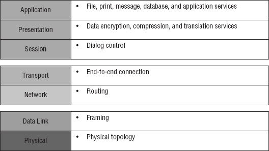
Figure 2.1 summarizes the functions that occur at each layer of the OSI model. With this in mind, you're ready to delve into what takes place at each layer in detail.

Some people like to use the mnemonic Please Do Not Throw Sausage Pizza Away to remember the seven layers (starting at Layer 1 and moving up to Layer 7). I didn't make that up!
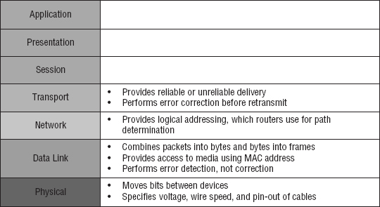
The OSI's seven layers are divided into two groups. The top three layers define the rules of how the applications working within host machines communicate with each other as well as with end users. The bottom four layers define how the actual data is transmitted from end to end. Figure 2.2 shows the top three layers and their functions, and Figure 2.3 shows the four lower layers and their functions.
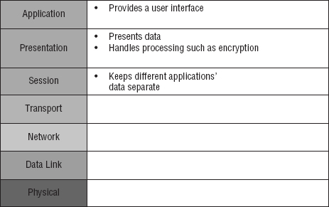
Looking at Figure 2.2, it's clear that actual users interface with the computer at the Application layer. It's also apparent that the upper layers are responsible for applications communicating between hosts. Remember that none of the upper layers “know” anything about networking or network addresses. That's the responsibility of the four bottom layers.
Figure 2.3 illustrates that the four bottom layers define how data is transferred through physical media, switches, and routers. These bottom layers also determine how to rebuild a data stream from a transmitting host to a destination host's application.
Okay—so let's start at the Application layer and work our way down the stack.
The Application Layer
The Application layer of the OSI model marks the spot where users actually communicate or interact with the computer. Technically, users communicate with the network stack through application processes, interfaces, or APIs that connect the application in use to the operating system of the computer. The Application layer chooses and determines the availability of communicating partners along with the resources necessary to make their required connections. It coordinates partnering applications and forms a consensus on procedures for controlling data integrity and error recovery. The Application layer comes into play only when it's apparent that access to the network will be needed soon. Take the case of Internet Explorer (IE). You could uninstall every trace of networking components from a system, such as TCP/IP, the network card, and so on, and you could still use IE to view a local HTML document without a problem. But things would definitely get messy if you tried to do something like view an HTML document that had to be retrieved using HTTP or nab a file with FTP or TFTP because IE responds to requests like those by attempting to access the Application layer. So what's happening is that the Application layer acts as an interface between the application program—which isn't part of the layered structure—and the next layer down by providing ways for the application to send information down through the protocol stack. In other words, IE doesn't reside within the Application layer—it interfaces with Application layer protocols when it needs to deal with remote resources.
The Application layer is also responsible for identifying and establishing the availability of the intended communication partner and determining whether sufficient resources for the requested communication exist.
These tasks are important because computer applications sometimes require more than just desktop resources. Often, they unite communicating components from more than one network application. Prime examples are file transfers and email as well as enabling remote access, network-management activities, and client-server processes like printing and information location. Many network applications provide services for communication over enterprise networks, but for present and future internetworking, the need is fast developing to reach beyond the limitations of current physical networking.
It's important to remember that the Application layer acts as an interface between application programs. For instance, Microsoft Word doesn't reside at the Application layer, it interfaces with the Application layer protocols. Later in Chapter 6, “Introduction to the Internet Protocol,” I'll tell you all about key programs or processes that actually do reside at the Application layer, like FTP and TFTP.
The Presentation Layer
The Presentation layer gets its name from its purpose: it presents data to the Application layer and is responsible for data translation and code formatting.
A successful data-transfer technique is to adapt the data into a standard format before transmission. Computers are configured to receive this generically formatted data and then convert it back into its native format for reading—for example, from EBCDIC to ASCII. By providing translation services, the Presentation layer ensures that the data transferred from one system's Application layer can be read and understood by the Application layer on another's.
The OSI has protocol standards that define how standard data should be formatted. Tasks like data compression, decompression, encryption, and decryption are all associated with this layer. Some Presentation layer standards are even involved in multimedia operations.
The Session Layer
The Session layer is responsible for setting up, managing, and then tearing down sessions between Presentation layer entities. This layer also provides dialog control between devices, or nodes. It coordinates communication between systems and serves to organize their communication by offering three different modes: simplex, half duplex, and full duplex. To sum up, the Session layer basically keeps applications’ data separate from other applications’ data.
The Transport Layer
The Transport layer segments and reassembles data into a data stream. Services located in the Transport layer handle data from upper-layer applications and unite it onto the same data stream. They provide end-to-end data transport services and can establish a logical connection between the sending host and destination host on an internetwork.
The Transport layer is responsible for providing the mechanisms for multiplexing upper-layer applications, establishing virtual connections, and tearing down virtual circuits. It also hides the many and sundry details of any network-dependent information from the higher layers facilitating data transfer.
We'll cover Transmission Control Protocol (TCP) and User Datagram Protocol (UDP) thoroughly in Chapter 6, but if you're already familiar with them, you know that they both work at the Transport layer. You also know that TCP is a reliable service and UDP is not. These two protocols give application developers more options because they have a choice between them when they're working with TCP/IP protocols.
The term reliable networking relates to the Transport layer and means that acknowledgments, sequencing, and flow control will be used.
The Transport layer can be connectionless or connection-oriented, but it's especially important for you to really understand the connection-oriented portion of the Transport layer. So let's take some time to delve into the connection-oriented (reliable) protocol of the Transport layer now.
Connection-Oriented Communication
Before a transmitting host starts to send segments down the model, the sender's TCP process contacts the destination's TCP process to establish a connection. The resulting creation is known as a virtual circuit. This type of communication is called connection-oriented. During this initial handshake, the two TCP processes also agree on the amount of information that will be sent in either direction before the respective recipient's TCP sends back an acknowledgment. With everything agreed on in advance, the path is paved for reliable communication to take place.
Figure 2.4 depicts a typical reliable session taking place between sending and receiving systems. Both of the hosts’ application programs begin by notifying their individual operating systems that a connection is about to be initiated. The two operating systems communicate by sending messages over the network confirming that the transfer is approved and that both sides are ready for it to take place. After all of this required synchronization occurs, a connection is fully established and the data transfer begins. This virtual circuit setup is called overhead.

While the information is being transferred between hosts, the two machines periodically check in with each other, communicating through their protocol software to ensure that all is going well and that data is being received properly.
Let me sum up the steps in the connection-oriented session—the three-way handshake—pictured in Figure 2.4:
- The first “connection agreement” segment is a request for synchronization.
- The next segments acknowledge the request and establishes connection parameters—the rules—between hosts. These segments request that the receiver's sequencing is synchronized here as well so that a bidirectional connection is formed.
- The final segment is also an acknowledgment. It notifies the destination host that the connection agreement has been accepted and that the connection has been established. Data transfer can now begin.
I know I went into a lot of detail about this connection setup, and I did that so you would have a really clear picture of how it works. You can refer to this entire process as “the three-way handshake” I already mentioned, known as SYN, SYN/ACK, ACK or synchronize, synchronize-acknowledgment, acknowledgment.
That sounds pretty simple, but things don't always flow so well. Sometimes congestion can occur during a transfer because a high-speed computer is generating data traffic a lot faster than the network can handle transferring it. A bunch of computers simultaneously sending datagrams through a single gateway or to a destination can also clog things up. In the latter case, a gateway or destination can become congested even though no single source caused the problem. Either way, the problem is like a freeway bottleneck—too much traffic for too small a capacity. It's not usually one car that's the problem; it's that there are just too many cars on that particular route.
Flow Control
Data integrity is ensured at the Transport layer by maintaining flow control and by allowing users to request reliable data transport between systems. Flow control provides a means for the receiver to govern the amount of data sent by the sender. It prevents a sending host on one side of the connection from overflowing the buffers in the receiving host—an event that can result in lost data. Reliable data transport employs a connection-oriented communications session between systems, and the protocols involved ensure that the following will be achieved:
- The segments delivered are acknowledged back to the sender upon their reception.
- Any segments not acknowledged are retransmitted.
- Segments are sequenced back into their proper order upon arrival at their destination.
- A manageable data flow is maintained in order to avoid congestion, overloading, and data loss.
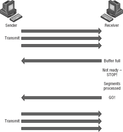
Okay, so what happens when a machine receives a flood of datagrams too quickly for it to process? It stores them in a memory section called a buffer. But this buffering tactic can only solve the problem if the datagrams are part of a small burst. If not, and the datagram deluge continues, a device's memory will eventually be exhausted, its flood capacity will be exceeded, and it will react by discarding any additional datagrams that arrive like a dam spilling over!
This sounds pretty bad, and it would be if it weren't for the transport function network flood-control systems that actually work really well. But how? Well, instead of just dumping resources and allowing data to be lost, the transport can issue a “not ready” indicator to the sender, or source, of the flood, as shown in Figure 2.5. This mechanism works kind of like a stoplight, signaling the sending device to stop transmitting segment traffic to its overwhelmed peer. After the peer machine's receiver processes the segments abounding in its memory reservoir (its buffer), it sends out a “ready” transport indicator. When the machine waiting to transmit the rest of its datagrams receives this “go” indictor, it resumes its transmission.
During fundamental, reliable, connection-oriented data transfer, datagrams are delivered to the receiving host in exactly the same sequence they're transmitted. So if any data segments are lost, duplicated, or damaged along the way, a failure notice is transmitted. This error is corrected by making sure the receiving host acknowledges it has received each and every data segment, and in the correct order.
To summarize, a service is considered connection-oriented if it has the following characteristics:
- A virtual circuit is set up (such as a three-way handshake).
- It uses sequencing.
- It uses acknowledgments.
- It uses flow control.
Windowing
Ideally, data throughput happens quickly and efficiently. And as you can imagine, it would be slow if the transmitting machine had to wait for an acknowledgment after sending each segment. But because time is available after the sender transmits the data segment and before it finishes processing acknowledgments from the receiving machine, the sender uses the break as an opportunity to transmit more data. The quantity of data segments (measured in bytes) that the transmitting machine is allowed to send without receiving an acknowledgment is represented by something called a window.
Windows are used to control the amount of outstanding, unacknowledged data segments.
It's important to understand that the size of the window controls how much information is transferred from one end to the other. Although some protocols quantify information by observing the number of packets, TCP/IP measures it by counting the number of bytes.
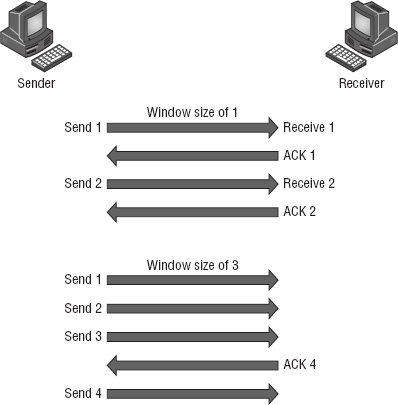
Figure 2.6 illustrates two window sizes—one set to 1 and one set to 3. In this simplified example, both the sending and receiving machines are workstations.
When you've configured a window size of 1, the sending machine waits for an acknowledgment for each data segment it transmits before transmitting another. If you've configured a window size of 3, the sending machine is allowed to transmit three data segments before an acknowledgment is received. In reality, the window size actually delimits the amount of bytes that can be sent at a time.
If a receiving host fails to receive all the segments that it should acknowledge, the host can improve the communication session by decreasing the window size.
Acknowledgments
Reliable data delivery ensures the integrity of a data stream being sent from one machine to the other through a fully functional data link. It guarantees that the data won't be duplicated or lost. This is achieved through something called positive acknowledgment with retransmission—a technique that requires a receiving machine to communicate with the transmitting source by sending an acknowledgment message back to the sender when it receives data. The sender documents each segment it sends and waits for this acknowledgment before sending the next segment. When it sends a segment, the transmitting machine starts a timer and retransmits if it expires before an acknowledgment is returned from the receiving end.
In Figure 2.7, the sending machine transmits segments 1, 2, and 3. The receiving node acknowledges it has received them by requesting segment 4. When it receives the acknowledgment, the sender then transmits segments 4, 5, and 6. If segment 5 doesn't make it to the destination, the receiving node acknowledges that event with a request for the segment to be resent. The sending machine will then resend the lost segment and wait for an acknowledgment, which it must receive in order to move on to the transmission of segment 7.
The Transport layer doesn't need to use a connection-oriented service. That choice is up to the application developer. It's safe to say that if you're connection-oriented, meaning that you've created a virtual circuit, you're using TCP. If you aren't setting up a virtual circuit, then you're using UDP and are considered connectionless.
Transport Control Protocol (TCP) and User Datagram Protocol (UDP) are protocols that work at the Transport layer and will be covered in detail in Chapter 6.

Devices Used in an Internetwork
The following network devices operate at all seven layers of the OSI model:
- Network management stations (NMSs)
- Web and application servers
- Gateways (not default gateways)
- Network hosts
Several devices operate primarily at the Physical layer of the OSI model. These devices manipulate mainly the physical aspects of a network data stream—things like voltages, signal direction, and signal strength. The following four devices are the most popular and will be detailed in Chapter 5, “Networking Devices”:
- Network Interface Cards (NICs)
- Transceivers
- Repeaters
- Hubs
The Network Layer
The Network layer manages logical device addressing, tracks the location of devices on the network, and determines the best way to move data. This means that the Network layer must transport traffic between devices that aren't locally attached. Routers are Layer 3 devices that are specified at the Network layer and provide the routing services within an internetwork.
It happens like this: First, when a packet is received on a router interface, the destination IP address is checked. If the packet isn't destined for that particular router, the router looks up the destination network address in the routing table. Once the router chooses an exit interface, the packet is sent to that interface to be framed and sent out on the local network. If the router can't find an entry for the packet's destination network in the routing table, the router drops the packet.
Two types of packets are used at the Network layer:
Data Packets These are used to transport user data through the internetwork. Protocols used to support data traffic are called routed protocols. Two examples of routed protocols are Internet Protocol (IP) and Internet Protocol version 6 (IPv6), which you'll learn all about coming up in Chapter 7, “IP Addressing.”
Route-Update Packets These are used to update neighboring routers about the networks connected to all routers within the internetwork. Protocols that send route-update packets are called routing protocols, and some common ones are Routing Information Protocol (RIP), RIPv2, Enhanced Interior Gateway Routing Protocol (EIGRP), and Open Shortest Path First (OSPF). Route-update packets are used to help build and maintain routing tables on each router.
Figure 2.8 pictures a routing table. The routing table used by a router includes the following information:

Network Addresses These are protocol-specific network addresses. A router must maintain a routing table for individual routing protocols because each routing protocol keeps track of a network that includes different addressing schemes, like IP and IPv6. Think of it as a street sign in each of the different languages spoken by the residents who live on a particular street. If there were American, Spanish, and French folks on a street named Cat, the sign would read Cat/Gato/Chat.
Interface This is the exit interface a packet will take when destined for a specific network.
Metric This value equals the distance to the remote network. Different routing protocols use different ways of computing this distance. I'll cover routing protocols in Chapter 9, “Introduction to IP Routing.” For now, just know that some routing protocols, namely RIP, use something called a hop count—the number of routers a packet passes through en route to a remote network. Other routing protocols alternatively use bandwidth, delay of the line, and even something known as a tick count, which equals 1/18 of a second, to make routing decisions.
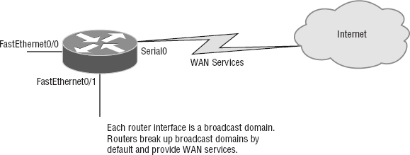
Routers break up broadcast domains, which means that by default, broadcasts aren't forwarded through a router. This is a good thing because it reduces traffic on the network. Routers also break up collision domains, but this can be accomplished using Layer 2 (Data Link layer) switches as well.
Broadcast and collision domains will be covered in detail in Chapter 5. For now, just remember that routers break up broadcast domains and switches break up collision domains.
Because each interface in a router represents a separate network, it must be assigned unique network identification numbers, and each host on the network connected to that router must use the same network number. Figure 2.9 demonstrates how a router works within an internetwork.
Here are some key points about routers that you really should commit to memory:
- Routers, by default, won't forward any broadcast or multicast packets.
- Routers use the logical address in a Network layer header to determine the next-hop router to forward the packet to.
- Routers can use access lists, created by an administrator, to control security on the types of packets that are allowed to enter or exit an interface.
- Routers can provide Layer 2 bridging functions if needed and can simultaneously route through the same interface.
- Layer 3 devices (routers, in this case) provide connections between virtual LANs (VLANs).
- Routers can provide quality of service (QoS) for specific types of network traffic.
A router can also be referred to as a Layer 3 switch. These terms are interchangeable.
The Data Link Layer
The Data Link layer provides the physical transmission of the data and handles error notification, network topology, and flow control. This means the Data Link layer ensures that messages are delivered to the proper device on a LAN using hardware (MAC) addresses and translates messages from the Network layer into bits for the Physical layer to transmit.
The Data Link layer formats the message into pieces, each called a data frame, and adds a customized header containing the destination and source hardware address. This added information forms a sort of capsule that surrounds the original message in much the same way that engines, navigational devices, and other tools were attached to the lunar modules of the Apollo project. These various pieces of equipment were useful only during certain stages of flight and were stripped off the module and discarded when their designated stage was complete. This is a great analogy for data traveling through networks because it works very similarly.
It's important for you to understand that routers, which work at the Network layer, don't care about where a particular host is located. They're only concerned about where networks are located and the best way to reach them—including remote ones. Routers are totally obsessive when it comes to networks, and in this instance, obsession is a good thing! The Data Link layer is responsible for the unique identification of each device that resides on a local network.
For a host to send packets to individual hosts on a local network as well as transmit packets between routers, the Data Link layer uses hardware addressing. Each time a packet is sent between routers, it's framed with control information at the Data Link layer. However, that information is stripped off at the receiving router, and only the original packet is left completely intact. This framing of the packet continues for each hop until the packet is finally delivered to the correct receiving host. It's important to understand that the packet itself is never altered along the route; it's only encapsulated with the type of control information required for it to be properly passed on to the different media types.
Figure 2.10 shows the Data Link layer with the Ethernet and Institute of Electrical and Electronics Engineers (IEEE) specifications. When you check it out, notice that the IEEE 802.2 standard is not only used in conjunction with the other IEEE standards, it also adds functionality to those standards.
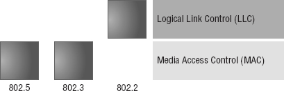
The IEEE Ethernet Data Link layer has two sublayers:
Media Access Control (MAC) Defines how packets are placed on the media. Contention media access is “first come, first served” access, where everyone shares the same bandwidth—hence the name. Physical addressing is defined here, as are logical topologies. What's a logical topology? It's the signal path through a physical topology. Line discipline, error notification (not correction), ordered delivery of frames, and optional flow control can also be used at this sublayer.
Logical Link Control (LLC) Responsible for identifying Network layer protocols and then encapsulating them, an LLC header tells the Data Link layer what to do with a packet once a frame is received. It works like this: A host receives a frame and looks in the LLC header to find out where the packet is destined—say, the IP protocol at the Network layer. The LLC can also provide flow control and sequencing of control bits.
Project 802
One of the major components of the Data Link layer is the result of the IEEE's 802 subcommittees and their work on standards for local area and metropolitan area networks (LANs/MANs). The committee met in February 1980, so they used the 80 from 1980 and the 2 from the second month to create the name Project 802. The designation for an 802 standard always includes a dot (.) followed by either a single or a double digit. These numeric digits specify particular categories within the 802 standard. These standards are listed in the following table.
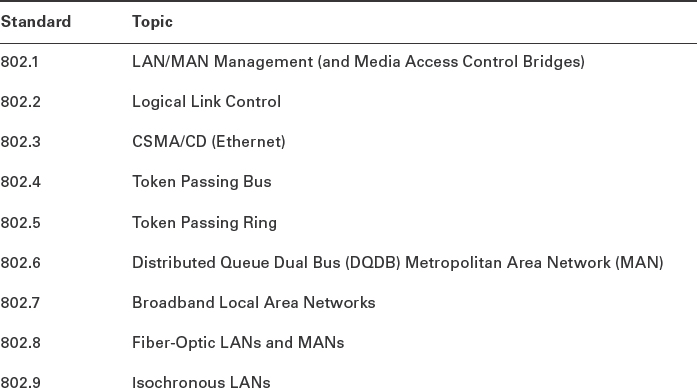
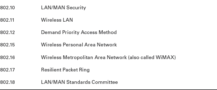
From this list in the sidebar, “Project 802”, you just need to remember that 802.3 calls out anything having to do with Ethernet and 802.11 is anything wireless.
The Physical Layer
Finally, we're hitting bottom. Well, not in a bad way—we've now arrived at the Physical layer, which does two important things: it sends bits and receives bits. Bits come only in values of 1 or 0—a Morse code with numerical values. The Physical layer communicates directly with the various types of actual communication media. Different kinds of media represent these bit values in different ways. Some use audio tones, and others employ state transitions—changes in voltage from high to low and low to high. Specific protocols are needed for each type of media to describe the proper bit patterns to be used, how data is encoded into media signals, and the various qualities of the physical media's attachment interface.
The Physical layer specifies the electrical, mechanical, procedural, and functional requirements for activating, maintaining, and deactivating a physical link between end systems. This layer is also where you identify the interface between the data terminal equipment (DTE) and the data communication equipment (DCE). (Some older phone company employees still call DCE data circuit-terminating equipment.) The DCE is usually located at the customer whereas the DTE is the attached device. The services available to the DTE are most often accessed via the DCE device, which is a modem or channel service unit/data service unit (CSU/DSU).
The Physical layer's connectors and different physical topologies are defined by the standards, allowing disparate systems to communicate.
Finally, the Physical layer specifies the layout of the transmission media, otherwise known as its topology. A physical topology describes the way the cabling is physically laid out, as opposed to the logical topology that we just talked about in “The Data Link Layer” section. The various physical topologies include Bus, Star, Ring, and Mesh, and were described in Chapter 1, “Introduction to Networks.”
Introduction to Encapsulation
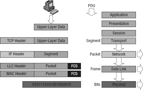
When a host transmits data across a network to another device, the data goes through encapsulation: It's wrapped with protocol information at each layer of the OSI model. Each layer communicates only with its peer layer on the receiving device.
To communicate and exchange information, each layer uses Protocol Data Units (PDUs). These hold the control information attached to the data at each layer of the model. They're usually attached to the header in front of the data field but can also be in the trailer, or end, of it.
At a transmitting device, the data-encapsulation method works like this:
- User information is converted to data for transmission on the network.
- Data is converted to segments, and a reliable connection is set up between the transmitting and receiving hosts.
- Segments are converted to packets or datagrams, and a logical address is placed in the header so each packet can be routed through an internetwork. A packet carries a segment of data.
- Packets or datagrams are converted to frames for transmission on the local network. Hardware (Ethernet) addresses are used to uniquely identify hosts on a local network segment. Frames carry packets.
- Frames are converted to bits, and a digital encoding and clocking scheme is used.
Figure 2.11 shows how user data is encapsulated at a transmitting host.
After you learn more foundational material about networking in the next few chapters, I'll come back to the encapsulation method and discuss it in a lot more detail in Chapter 6.
Modulation Techniques
In networks, modulation is the process of varying one or more properties of a waveform, called the carrier signal, with a signal that typically contains information to be transmitted.
Modulation of a waveform transforms a baseband (Ethernet or wireless) message signal into a passband signal (a passband [a band-pass filtered signal] is the range of frequencies or wavelengths that can pass through a filter without being attenuated). In current networks, modulation takes a digital or analog signal and puts it in another signal that can be physically transmitted.
A modulator is a device that performs modulation of a signal and a demodulator is a device that performs demodulation, the inverse of modulation. We typically just call these modems (from modulator–demodulator), which can perform both operations.
The purpose of digital modulation is to transfer a digital bit stream over an analog bandpass channel. (A good example would be data transmitting over the public switched telephone network, where a bandpass filter limits the frequency range to 300–3400 Hz, or over a limited radio frequency band.) The purpose of an analog modulation is to transfer an analog baseband (or lowpass) signal (for example, an audio signal, wireless network, or TV signal) over an analog bandpass channel at a different frequency.
Analog and digital modulation use something called frequency-division multiplexing (FDM), where several low-pass information signals are transferred simultaneously over the same shared physical network, using separate passband channels (several different frequencies).
The digital baseband modulation methods found in our Ethernet networks, and also known as line coding, are used to transfer a digital bit stream over a baseband channel. Baseband means that the signal being modulated used the complete available bandwidth.
Time-division multiplexing (TDM) is a method of transmitting and receiving many independent signals over a common signal path by means of synchronized network devices at each end of the transmission line so that each signal appears on the line only a fraction of time in an alternating pattern. The receiving end demultiplexes the signal back to its original form.
Summary
You're now armed with a ton of fundamental information. You're set to build on it and are well on your way to certification.
Let's take a minute to go over what you've learned in this chapter. We started by discussing internetworking models and the advantages of having them. I then discussed the OSI model—the seven-layer model used to help application developers design applications that can run on any type of system or network. Each layer has its special jobs and select responsibilities within the model to ensure that solid, effective communications do, in fact, occur. I provided you with complete details of each layer and discussed how you need to view the specifications of the OSI model.
I also discussed the encapsulation method used in networking. Encapsulation is a highly important concept to understand, and I'll continue to discuss it throughout this book.
This chapter finished with a brief introduction to modulation of digital and analog signals.
Exam Essentials
Remember the OSI layers. You absolutely must remember and understand the seven layers of the OSI model as well as what function each layer provides. The Application, Presentation, and Session layers are upper layers and are responsible for communicating from a user interface to an application. The Transport layer provides segmentation, sequencing, and virtual circuits. The Network layer provides logical network addressing and routing through an internetwork. The Data Link layer provides framing and placing of data on the network medium. The Physical layer is responsible for taking 1s and 0s and encoding them into a digital signal for transmission on the network segment.
Know the sublayers of the Data Link layer. In addition to the OSI layers, knowing the only layer that has sublayers and the functions of those sublayers is extremely important. The Data Link layer has two sublayers: LLC and MAC. The LLC sublayer is responsible primarily for the multiplexing of Network layer protocols. The MAC sublayer is responsible for physical addressing and determining the appropriate time to place data on the network.
Know the devices that operate at each layer of the OSI model. Hubs and repeaters see only bits, making them Layer 1 devices. Because all networking devices have physical connectivity to the network, they all operate at Layer 1, but hubs and repeaters operate only at this layer, whereas other devices work in higher layers. Nevertheless, we generally consider that a device operates at the highest layer it supports; that layer's functionality is the main reason we implement the device on the network. For example, switches and bridges are considered Layer 2 devices because they understand and make decisions based on Layer 2 addresses. Routers are Layer 3 devices for a similar reason; they deal with Layer 3 addresses. Networking devices, such as workstations that run applications, are said to operate at the Application layer (or you may hear that they operate at all layers) because they must include Application layer protocols that offer services to networked applications.
Written Lab
You can find the answers in Appendix A.
- Which layer chooses and determines the availability of communicating partners along with the resources necessary to make the connection, coordinates partnering applications, and forms a consensus on procedures for controlling data integrity and error recovery?
- Which layer is responsible for converting frames from the Data Link layer into electrical signals?
- At which layer is routing implemented, enabling connections and path selection between two end systems?
- Which layer defines how data is formatted, presented, encoded, and converted?
- Which layer is responsible for creating, managing, and terminating sessions between applications?
- Which layer manages the transmission of data across a physical link and is primarily concerned with physical addressing and the ordered delivery of frames?
- Which layer is used for reliable communication between end nodes over the network and provides mechanisms for establishing, maintaining, and terminating virtual circuits as well as controlling the flow of information?
- Which layer provides logical addressing that routers use for path determination?
- Which layer specifies voltage, wire speed, and connector pin-outs and moves bits between devices?
- Which layer combines bits into bytes and bytes into frames and uses MAC addressing?
Review Questions
You can find the answers in Appendix B.
- Host 1 sent a SYN packet to Host 2. What will Host 2 send in response?
- ACK
- NAK
- SYN/ACK
- SYN/NAK
- SYN
- TCP and UDP reside at which layer of the OSI model?
- 1
- 2
- 3
- 4
- Which layer of the OSI model provides a user interface in the form of an entry point for programs to access the network infrastructure?
- Application
- Transport
- Network
- Physical
- You are connected to a server on the Internet and you click a link on the server and receive a time-out message. What layer could be the source of this message?
- Application
- Transport
- Network
- Physical
- Which layer of the OSI model is responsible for code and character-set conversion as well as recognizing data formats?
- Application
- Presentation
- Session
- Network
- At which layers of the OSI model do bridges, hubs, and routers primarily operate, respectively?
- Which layer of the OSI model is responsible for converting data into signals appropriate for the transmission medium?
- Application
- Network
- Data Link
- Physical
- A receiving host has failed to receive all the segments that it should acknowledge. What can the host do to improve the reliability of this communication session?
- Send a different source port number.
- Restart the virtual circuit.
- Decrease the sequence number.
- Decrease the window size.
- Which Layer 1 devices can be used to enlarge the area covered by a single LAN segment? (Choose two.)
- Firewall
- NIC
- Hub
- Repeater
- RJ-45 transceiver
- Segmentation of a data stream happens at which layer of the OSI model?
- Physical
- Data Link
- Network
- Transport
- When data is encapsulated, which is the correct order?
- Data, frame, packet, segment, bits
- Segment, data, packet, frame, bits
- Data, segment, packet, frame, bits
- Data, segment, frame, packet, bits
- What are two purposes for segmentation with a bridge? (Choose two.)
- To add more broadcast domains
- To create more collision domains
- To add more bandwidth for users
- To allow more broadcasts for users
- Acknowledgments, sequencing, and flow control are characteristic of which OSI layer?
- Layer 2
- Layer 3
- Layer 4
- Layer 7
- Which of the following is true regarding sequencing and acknowledgments? (Choose all that apply.)
- The segments delivered are acknowledged back to the sender upon their reception.
- If a segment is not received, the virtual circuit must be restarted from the beginning at a slower transmit interval.
- Any segments not acknowledged are retransmitted.
- Segments are sequenced back into their proper order upon arrival at their destination.
- All segments are retransmitted on time slot intervals.
- What is the purpose of flow control?
- To ensure that data is retransmitted if an acknowledgment is not received
- To reassemble segments in the correct order at the destination device
- To provide a means for the receiver to govern the amount of data sent by the sender
- To regulate the size of each segment
- At which layer of the OSI model would you find IP?
- Transport
- Network
- Data Link
- Physical
- Of the following, which is the highest layer in the OSI model?
- Transport
- Session
- Network
- Presentation
- Routers perform routing at which OSI layer?
- Physical
- Data Link
- Network
- Transport
- Application
- Which of the following mnemonic devices can you use to remember the first letter of the name of each layer of the OSI model in the proper order?
- All People Seem To Need Processed Data.
- Always Should People Never Threaten Dog Police.
- Please Do Not Throw Sausage Pizza Away.
- All Day People Should Try New Professions.
- Which IEEE standard specifies the protocol for CSMA/CD?
- 802.2
- 802.3
- 802.5
- 802.11