
Chapter 16
Wide Area Networks
THE FOLLOWING COMPTIA NETWORK+ EXAM OBJECTIVES ARE COVERED IN THIS CHAPTER:
- 1.4 Explain the characteristics and benefits of various WAN technologies
- 1.7 Differentiate between network infrastructure implementations
- WAN
- MAN
- LAN
- 4.8 Given a scenario, troubleshoot and resolve common WAN issues
- Loss of internet connectivity
- Interface errors
- Split horizon
- DNS issues
- Interference
- Router configurations
- Customer premise equipment
- Smart jack/NIU
- Demarc
- Loopback
- CSU/DSU
- Copper line drivers/repeaters
- Company security policy
- Throttling
- Blocking
- Fair access policy/utilization limits
- Satellite issues
- Latency
- 2.2 Given a scenario, analyze metrics and reports from monitoring and tracking
- Link status
- Interface monitoring
- Errors
- Utilization
- Discards
- Packet drops
- Interface resets
- Speed and duplex

We have wide area networks (WANs) and local area networks (LANs), but what's really the key difference between the two? Clearly there's the distance factor, but these days, wireless LANs can cover respectable turf. Is it a bandwidth thing? Not so much—some seriously big pipes can be had for a price in many places, so what is it that actually sets the two apart?
One of the main ways a WAN differs from a LAN is that you usually own your LAN infrastructure, whereas WAN infrastructure is typically leased from a service provider instead. To be honest, modern technologies actually blur this definition a bit, but it still fits neatly into the context of CompTIA's Network+ exam objectives. Anyway, I've already talked about the data link that you usually own (Ethernet), so it's time to explore the kind you usually don't own—the type most often leased from a service provider.
You've probably heard of T-series connections, which are leased line connections that reserve or dedicate lines to provide paths between network segments. In addition to these, we'll survey broadband services, including the array of Digital Subscriber Line (DSL) and cable modem connectivity that most of us use to connect to the Internet from home. We'll even check out a more modern home-based option known as a passive optical network, which essentially means running fiber to a specific site.
Cellular technologies have evolved over the years, and more and more people are opting to use them for connecting to the Internet. For this reason, we'll talk about HSPA+, WiMAX, and LTE, and discuss the evolution of 1G, 2G, 3G, and 4G.
We'll also spend some time looking into the different kinds of WAN connectivity achieved through other kinds of links and over different transmission media. WAN technologies run the gamut from short-range Bluetooth to the serious, long-distance coverage available via satellite transmissions. I'll also focus on key WAN protocols, which are basically sets of rules that establish exactly how long-distance communication and connectivity should occur. We'll even review some not-so-modern technologies like Integrated Services Digital Network (ISDN), Frame Relay, and Asynchronous Transfer Mode (ATM), and talk about the legacy phone-company network and some of its terminology, too. I'll guide you through everything you'll need to know about different speed links—including T1s and E1s, SONET fiber links, and the plain old telephone service (POTS) lines that connect us to the Public Switched Telephone Network (PSTN). With all of these subjects nailed down, you'll be well equipped with the knowledge you'll need to confidently meet the CompTIA Network+ objectives!

For up-to-the-minute updates for this chapter, please see www.lammle.com/networkplus or the book's website at www.sybextestbanks.wiley.com.
What's a WAN?
As local area networks grew and developed, it became increasingly necessary to be able to connect their resources together over long distances. We initially met these challenges via the phone company network—the Public Switched Telephone Network (PSTN)—and the first successful network able to establish voice communications over disparate locations was born.
Few of us remember back to a world without phone service, which made PSTN an obvious solution. It was already a fully operational, circuit-switching network, enabling every phone call to establish a unique circuit from one endpoint (phone) to another through a path of switches. So, instead of reinventing the wheel to design LANs, early network planners used packet switching as their communications-delivery method. As you can imagine, wiring these packet-switched networks to enable communication over vast locales wasn't exactly something we could get done quickly, so even wide area networks (WANs) used the existing phone company network back in the day! But all solutions aren't created equally, and this one just wasn't so great due to its hefty price tag and because it imposed some ugly data transfer limitations on very networks it served.
So that's the history for you, but know that it's not a thing of the past—yet. Today's WANs are communication networks that cover broad geographic areas, and they still frequently use phone companies (service providers) in concert with their circuit-switched networks to connect LANs together. Competition can be a great motivator, and with the Internet entering the scene, giving us an alternative way to connect LANs, we benefit tremendously from the resulting reduction in the cost of our connectivity. These new connection options, along with their related protocols and technologies, can greatly reduce the cost of a WAN's infrastructure, and lowered transport costs are a huge relief for network administrators and designers alike!
An important fact to lock into memory is that WAN protocols and technologies all occupy at least two of the OSI model's lower three layers—the Physical layer, Data Link layer, and sometimes the Network layer as well. Coming up, we'll examine the various types of connections, technologies, topologies, and devices used with WANs as well as how to create WAN connections using different transmission media such as air (wireless), space (satellite), and both copper and glass fiber for wired connections. But before we go there, you'll need to know some basic WAN terms.
Defining WAN Terms
Before you run out and order a WAN service type from a provider, you really need to understand the following terms that service providers typically use:
Customer Premises Equipment (CPE) Customer premises equipment (CPE) is equipment that's owned by the service provider but located on the subscriber's (your) property.
CSU/DSU Channel service unit/data service unit (CSU/DSU) is a Layer 1 device that connects the serial ports on your router to the provider's network and connects directly to the demarcation point (demarc) or location. These devices can be external, as shown in Figure 16.1, or they can be internal cards on the router. The CSU/DSU provides clocking of the line to the CPE—in this case, your router—and provides other important options, like voltage regulation.
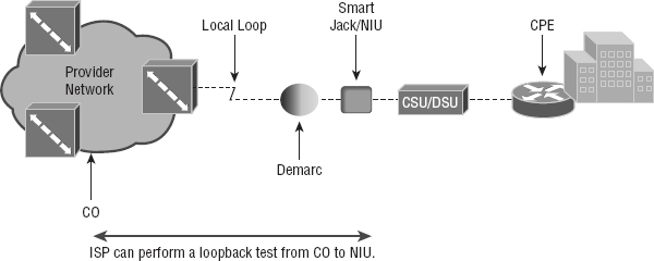
Smart Jack/NIU As you can see, there's a smart jack, or network interface unit (NIU), installed between the demarcation location and the CSU/DSU at the customer premises equipment (CPE) location. But why is it there and what does it do? For starters, a smart jack can provide signal conversion by converting codes and protocols (e.g., framing types) into something the customer equipment requires. Plus, the NIU can buffer and/or regenerate the signal to compensate for signal degradation from line transmission. This is very similar to what a repeater does.
But there's more. Smart jacks also typically provide diagnostic capabilities to the ISP, something a demarcation location just can't. A very common and vital capability gained via a smartjack is the ability to perform a loopback test, where the signal from the provider is transmitted back to the provider's location. Doing this allows the ISP to test the line from the central office, without the need to have test equipment or a technician at the customer site. Of course, this loopback test will bring down the line, but then again, they wouldn't need to perform the test if you didn't call in a problem in the first place!
Demarcation Point Just so you're clear, a demarc is the precise spot where the service provider's or local exchange carrier's responsibility ends and the CPE begins. It's generally a device in a telecommunications closet owned and installed by the telecommunications company (telco). It's your responsibility to cable—a task called extended demark—from this box to the CPE, which is usually a connection to a CSU/DSU or ISDN interface.
Copper Line Drivers/Repeaters A copper line driver or repeater allows for a demarc extension length of up to 5,000 feet from the telephone company's demarc. These can be used to connect equipment across a campus, between floors of a high-rise office building, even between office buildings with underground cable connections.
Local Loop A cable consisting of a pair of copper wires called the local loop connects the demarc to the closest switching office, known as a central office (CO).
Central Office (CO) A phone company building that connects the customer's network to the provider's switching network. It's also good to know that a CO is sometimes referred to as a point of presence (POP).
Toll Network The toll network is a trunk line inside a WAN provider's network. This network is a collection of switches and facilities owned by the ISP.
With all this said, let's take another look at Figure 16.1, which uses all these items to describe a typical WAN connection.
You would find the typical WAN (as shown in Figure 16.1) when you order a T1 or Frame Relay circuit. Definitely familiarize yourself with these terms because they're crucial to understanding WAN technologies.
The Public Switched Telephone Network
As I mentioned at bit earlier, the portion of the PSTN that runs from your house to the rest of the world is known as plain old telephone service (POTS), and it's a popular method for connecting remote users to a local network due to simplicity, low cost, and easy installation. Connecting to PSTN via ISDN, DSL, a cable modem, or even your cellular service is becoming increasingly popular.
Two key concepts to keep in mind about PSTN are public and switched. Public basically means that, for a fee, anyone can lease the use of the network without being required to run any cabling. Switched explains how the phone system works. Even though one or more wires are actually connected to your home and/or office, all of them aren't always online or being used. Any dormant wires are still available to you in their offline state so you can get online and join the network whenever you want. Think of it as like a standing reservation, and your phone number is used as an ID to access it. Because you initiate the connection by dialing a certain phone number, it's easy to imagine how technically impractical, if not impossible, it would be for this method to work if every phone number stayed connected all the time. If connections stayed active 24/7, the resulting backbone cabling requirements and problems would be insurmountable.
Take, for instance, the US and worldwide telephone systems. The actual numbering sequence varies in other countries, but the concept is identical. The phone company runs the local loop from the demarc to the CO. All the pairs from all the local loop cables within a small regional area come together at a central point a lot like a patch panel in a LAN based on unshielded twisted-pair (UTP) cable.
This centralized point has a piece of equipment attached called a switch, which opens a communications session when it's initiated by a user who's dialed the phone number of the receiver and keeps it open until the “conversation” ends and the session is closed. On one side of the switch is the neighborhood wiring, and on the other side are lines that connect to either another switch or a local set of wiring.
To make this concept really clear, picture the following scenario: When you want to make a call, you pick up the phone, which completes a circuit, and in most cases that gives you a dial tone. The tone is the switch's way of saying, “I'm ready.” When you don't get that dial tone, it means that either there's a break in the equipment chain or the switch is too busy processing other requests. In many areas of the world, you hear a fast on-and-off tone (somewhat like a fast busy signal) after giving a command string (phone number) to the local switch. This means that the other switches that the local switch is attempting to communicate with are too busy at that time.
Recently, this tone thing has been replaced with a voice recording saying something like, “We're sorry. All circuits are busy. Please try your call later.” Sometimes you even get offered the shady-sounding “For only 99 cents, you can interrupt this call” added to the message. This happens frequently on holidays or during natural disasters because the local area's phone company uses only the minimum number of wires, called trunk lines, required to handle the norms of usage capacity plus a few auxiliary lines for peak usage. They keep equipment to a minimum because wiring and switches are really expensive; it's essentially a trade-off between providing 100 percent uptime and keeping the costs of leasing the connection from the phone company reasonably affordable.
WAN Connection Types
With all that in mind, it's time to go over the various types of WAN connections you'll find on the market today. Figure 16.2 shows the different WAN connection types that can be used to connect your LANs together.
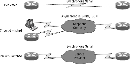
Let's talk about the different WAN connection types you see pictured here:
Dedicated (Leased) Lines These are usually referred to as point-to-point or dedicated connections. A dedicated leased line is a preestablished WAN communications path that goes from the CPE through the DCE switch and then over to the CPE of the remote site. The CPE enables DTE networks to communicate at any time with no cumbersome setup procedures to muddle through before transmitting data. When you've got plenty of cash, this is the way to go because it uses synchronous serial lines up to 45Mbps. High-Level Data Link Control (HDLC) and Point-to-Point Protocol (PPP) encapsulations are frequently used on leased lines.
Circuit Switching When you hear the term circuit switching, think phone call. The big advantage is cost—you only pay for the time you actually use. No data can transfer before an end-to-end connection is established. Circuit switching uses dial-up modems or ISDN and is used for low-bandwidth data transfers. I know what you're thinking: “Modems? Did he say modems? Aren't those only in museums now?” After all, with all the wireless technologies available, who uses modems these days? Believe it or not, some people still use ISDN. It's still viable, and there are many places on Earth where you definitely need a modem to get connected. Also, circuit switching can actually be used in some of the newer WAN technologies as well.
Packet Switching This WAN switching method allows you to share bandwidth with other companies to save money. Packet switching can be thought of as a network that's designed to look like a leased line yet charges you more like circuit switching does. But less isn't always more—there's definitely a downside, and if you need to transfer data constantly, just forget about this option. Instead, get yourself a leased line. Packet switching will only work for you if your data transfers are the bursty type, not continuous. Frame Relay and the super-old X.25 are packet-switching technologies with speeds that can range from 56Kbps up to T3 (45Mbps).
LANs use packet switching technology. The source and destination addresses in the packet header guide the network as it moves the packet closer and closer to the destination in the same way the post office takes an addressed letter and keeps it moving incrementally closer to its destination. This approach avoids the necessity of establishing an actual contiguous electrical circuit from one end to the other—the method phone companies use to facilitate a phone call in their circuit-switched networks.
Most WAN connections work on the phone company's circuit-switched network where the point-to-point nature of most connections eliminates the need for addressing because there's only one possible destination between endpoints. But you still need a proper addressing scheme within your LAN to ensure that data packets reach their correct destinations.
Bandwidth or Speed
Satisfying the need for speed involves moving large volumes of data, voice, and video loaded packets across vast distances to communicate. Companies’ volume requirements have grown right along with their appetites for ever bigger, faster connections. Speed, typically made possible with more bandwidth, is measured in bits per second or multiples of bits per second, such as kilobits (thousands of bits) per second.
And no surprise here—the winner of the “Slowest WAN Connection” prize is the much-maligned dial-on-demand dial-up connection. Modern dial-up modems typically have a maximum theoretical transfer speed of 56Kbps, although in most cases 40Kbps to 50Kbps is the norm. Factors such as phone-line noise as well as the quality of the modem itself play a large part in determining connection speeds. Modems are required to modulate/demodulate the signal, which means translating the analog signal our ears hear into a digital stream for transfer across a digital network. Some connections may be as slow as 20Kbps in extremely “noisy” environments like hotel rooms where phone lines are shared with an abundant number of extensions.
Megabyte (MB) and gigabyte (GB) usually refer to the amount of storage capacity available, whereas bandwidth and speed refer to units that measure how much data (bits) can be sent per second. In the networking world, speed is essentially the measurement of how fast the data flows (Hz) and also refers to how fast data flows within memory systems. Sometimes the terms bandwidth and speed are used interchangeably.
T-Series Connections
The basic, entry-level in bandwidth or speed for leased lines that provide synchronous connections between sites is known as the T1. It serves up 24 Digital Signal 0 (DS0) 64Kbps channels in the United States, Japan, and South Korea. There's a slightly bigger/faster version with 32 DS0 channels that's available in Europe and called the E1 or E carrier line.
T1s use Digital Signal 1 (DS1) bit patterns to transmit packets; DS1 has to do with the service to be sent over a T1—originally, 24 digitized voice channels. The terms T1 and DS1 have become synonymous and include a bunch of different services from voice to data to clear-channel pipes. The line speed is always consistent at 1.544Mbps (millions of bits per second), but the payload can vary greatly. For trivia lovers, T1 came from the carrier letter or part number assigned by AT&T to the technology.
But That Doesn't Add Up!
Twenty-four of these channels are a composite of 1.536Mbps, not 1.544Mbps! Why is there a difference? The reason is that after a byte (8 bits) of data is sent from each channel (24 × 8 = 192 bits), there is an extra bit used for synchronizing called a frame bit. Hence, 193 bits are sent, and this increase of 1 bit per 192 causes the speed to increase to 1.544Mbps.
T-series connections are digital connections that you can lease from the telephone company. They can use copper pairs like regular phone lines, or they can be brought in as part of a backbone, which is also called a trunk line. At this point, T-series connections use time-division multiplexing, or TDM, to divide the bandwidth into channels of equal bit rate.
T-series connection types are denoted by the letter T followed by a number. Each connection type differs in its speed and in the signal used to multiplex the channels. Table 16.1 lists some of the T-series connections and their maximum data rates. The most commonly used T-series lines are T1 and T3.

The T1 Connection
So a T1 is a 1.544Mbps digital connection that's typically carried over two pairs of copper wires. This 1.544 Mbps connection uses DS1 and aggregates 24 discrete, 64Kbps channels that use DS0, which refers to the time slots within a channel. Each channel can carry either voice or data. In the POTS world, T1 lines are used to convert and bundle analog phone conversations over great distances due to the better quality of a digital signal and the use of a great deal less wiring than would be needed if each pair carried only one call. This splitting into independent channels also allows a company to combine voice and data over one T1 connection or to use the T1 as if it were an unchannelized 1.544Mbps pipe. You can also order a fractional T1 (FT1) circuit that's delivered on a T1 but doesn't allow the use of all 24 channels.
The European version of the T1 is the E1, which operates at 2.048Mbps and uses 32 64Kbps channels (32 DS0s). It was designed later, based on T1s, and is a little bigger. You'll also find the J1, which is the Japanese version of the T1 and operates at 1.544Mbps, just like the T1.
![]()
What's a Good Speed for a Business?
Many of you who happen to be in charge of setting up your company's Internet connection may think that a T1 is definitely what you should go with. Unfortunately, T1 connections to the Internet can be really pricey. If you're in the business of selling Internet connections as an ISP is, you can justify spending the big bucks on large bandwidth pipes. Another example of when it would make sense for you to opt for a T1 is if you have loads of users on your network—at least 50 or more.
But even if you've got bunches of users on your network, it could be worth it to check out alternative solutions that offer similar speeds at lower costs, like DSL or a cable modem. You can always use a virtual private network (VPN) if you need the security. And there are inexpensive wireless connection options out there as well that provide good bandwidth. Do your research before you buy!
The T3 Connection
A T3 line works similarly to a T1 connection but carries a whopping 44.736Mbps. This is equivalent to 28 T1 circuits and a whopping 672 DS0 channels! It uses a signal known as Digital Signal 3 (DS3) that's definitely not the same as DS1, which is generally delivered over fiber-optic cable. Many local ISPs have T3 connections to their next-tier ISPs. Other entities that often opt for T3 are large multinational companies because they need the capacity to send voice and data between their major regional offices. And don't forget that the reason the math doesn't quite work out is because of those frame bits!
As it goes with the T1, the T3's European counterpart is the E3, which operates at 34.368Mbps. The Japanese Digital Hierarchy specifies the J3 circuit, which operates at 32.064Mbps.
This Doesn't Add Up Again!
Why does an E1 have more capacity than a T1 but a T3 has more capacity than an E3? E and T lines are incremented differently. A T1 is 28 T1s, while an E3 is only 16 E1s.
Transmission Media
Another aspect of WAN technologies that can have a big effect on the speed, bandwidth, and the volume of data that can be transferred is the type of transmission media. Wireless transmissions use air as transmission media. This not only creates a bit of a challenge concerning security, it also presents us with signal degradation—the further the signal has to travel from the original source, the weaker it gets. A solution to this last snag comes to us via microwave repeaters, which retransmit signals through the air and bolster them. This approach is a lot more efficient because it can preserve signal strength over much greater distances.
The most far-reaching technology uses the air and even empty space to send electromagnetic signals to satellites from which they are then resent to distant geographic locations.
Wired Connections
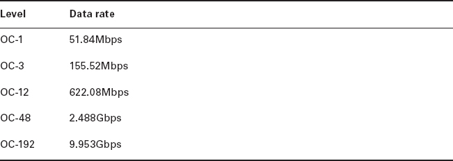
Back on Earth, wired connections use either copper wire or glass fiber to carry bits as voltages or light pulses, respectively. That attenuation issue I just talked about under wireless technology, where the signal gradually weakens over distances, also relates to copper wire transmissions and limits the length of wire you can use. Fiber offers a lot more bandwidth and it's a lot less susceptible to noise, but it also costs a lot more to buy and install! In the United States, the standard for synchronous data transmission on optical fiber is called Synchronous Optical Network (SONET). The international equivalent of SONET is Synchronous Digital Hierarchy (SDH). SONET defines a base data rate, or throughput, of 51.84Mbps, and multiples of this rate are known as optical carrier (OC) levels, like OC-3, OC-12, and so on. Table 16.2 depicts common OC levels and their associated data rates.
Regardless of the media used to carry WAN traffic, the growing volume of voice and video traversing data networks has led to new traffic problems. Regular data traffic can arrive out of order and be reassembled back into its original order on the receiving end, but voice and video data require real-time delivery to be intelligible. Clearly, this makes regular data a lot less vulnerable to congestion or busy traffic conditions that can delay voice and video communications and totally mess them up. The explosion in the popularity and amount of multimedia being sent over data networks is a big reason the never-ending quest for greater bandwidth and speed to avoid traffic jams on WAN links is so vital today.
Wavelength Division Multiplexing
Wavelength Division Multiplexing (WDM) is a technology that multiplexes several optical carriers on a single optical fiber by using different wavelengths. Remember, fiber-optic signals are light, so using different wavelengths of the light spectrum is somewhat like using different frequencies in a radio wave.
Dense Wavelength Division Multiplexing (DWDM) multiplexes within a specific band (1550 nm), allowing for the use of erbium-doped fiber amplifiers (EDFAs) that boost the signal. This allows for upgrading the bit rate of a single strand line by simply replacing equipment at either end of the line. The system consists of the following:
- DWDM terminal multiplexer
- Intermediate line repeater (every 80–100 km)
- Intermediate terminal multiplexer (remote amplification site)
- DWDM terminal de-multiplexer
Coarse Wavelength Division Multiplexing (CWDM) uses larger chunks of the light spectrum, and is defined by wavelengths, whereas DWDM is defined by frequencies and fits 40-plus channels into the same frequency range used by just 2 CWDM channels. So why use CWDM at all then? Because CWDM can match the basic capabilities of DWDM at a lower capacity at a significant discount! This allows ISPs to help customers in a Metropolitan Area Network (MAN) physical location where fiber is still too pricey to implement.
Passive Optical Network
Passive Optical Network (PON), also called fiber to the premises, is a new option for connecting homes and business to the Internet. It is point-to-multipoint technology with a single fiber strand used for multiple premises (typically 16–28). Unpowered optical splitters are used in the process and are the reason for using the term passive.
The system consists of an optical line termination (OLT) at the telco's office and a number of optical network units (ONUs) near end users. These systems typically have downlink speeds of 155Mbps to 655Mbps and uplink bursts to 155Mbps.
Wireless Technologies
Now let's get back to that distance issue. You know that different technologies offer different distance ranges and that optical fiber carries signals much further than copper cabling can. You also know that fiber comes with a much higher price tag to match its higher capacity and that it's much harder to install.
By now, most of us know what Bluetooth is—a type of wireless technology that's only used for short-distance wireless transmissions. Bluetooth is actually a wireless protocol that creates personal area networks (PANs). It utilizes short-range communications technology enabling data transmission between fixed and/or mobile devices. Most of us have mobile phones and those who have smartphones can even get their email, news, directions to where they're headed, and the best Italian restaurant, and once there, they can tell friends where to meet them and post it all on social media in real time. But it's already illegal to talk on your cell while driving in some US states and, as time goes on, likely more, if not all. Even using a wireless headset while driving can get you in trouble in some places. Those headsets, along with wireless keyboards and mice, all use Bluetooth technology.
Bluetooth uses a radio technology called Frequency Hopping Spread Spectrum that chops up the data being sent and transmits chunks of it through the air on up to 75 different frequencies in the 2.4GHz range. The transmitter and receiver change frequencies or channels in a prearranged pattern. Getting all of our wireless toys to play nicely with each other and synch up can be a hassle initially, but meeting that need is exactly what the people who created Bluetooth intended to do—develop a single digital wireless protocol, capable of connecting multiple devices and overcoming problems arising from trying to synchronize them. Bluetooth achieves this goal and even allows us to synch our cars with our phones to chat away legally while driving again!
Microwave radio relay is a technology for transmitting digital and sometimes even analog signals between two locations on a line-of-sight radio path through the atmosphere. During microwave radio relay, radio waves are transmitted between the two locations with directional antennas that form a fixed radio connection between them. A really long connected series of links can form line-of-sight transcontinental communication systems. Now, if this sounds familiar, it should—if you didn't skip Chapter 12, “Wireless Networking,” that is! Anyway, although having a dedicated microwave connection is still common because it allows you to purchase your own frequency range from the FCC to ensure that you don't get any interference, a much less costly installation is the wireless 802.11 specification, which provides us with long-distance solutions and a healthy amount of bandwidth to boot.
A communications satellite (comsat) is an artificial satellite stationed in space for telecommunications purposes. Modern communications satellites use a variety of orbits. Here's a list of them:
- Geostationary orbits
- Molniya orbits (molniya means lightening in Russian), named after a series of communications satellites from Russia
- Low-polar and non-polar Earth orbits from which the satellite can first boost communications signals and then send them back to earth
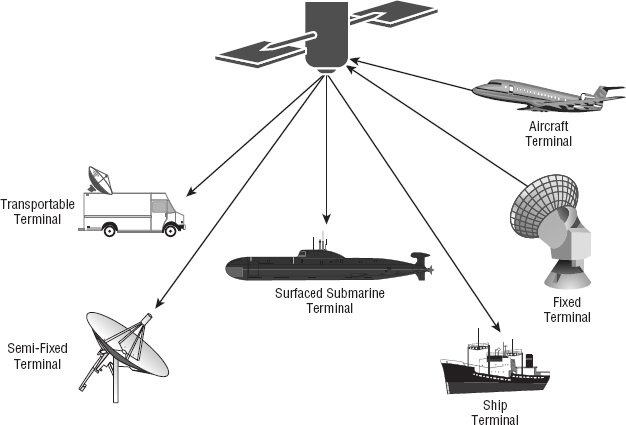
There are other elliptical orbits too, but I'm not going to go into them in this book because you're not reading this to help you get your FCC license. Instead, you want to pass the CompTia Network+ exam, and to do that, you do need to understand point-to-multipoint services and how communications satellites provide microwave radio relay technology, as shown in Figure 16.3.
This technology is also used for mobile applications like GPS communications to ships, vehicles, planes, and handheld terminals as well as for fun stuff like watching football on satellite HDTV and radio broadcasting. These all require capabilities that are impractical or impossible to use with other technologies like cable.
So yeah, this satellite thing is pretty awesome, but of course it comes with a few problems too. First of all, it's expensive, and although it isn't necessarily slow, there's a lot of latency because of the time it takes to get from your terminal to the satellite to the provider and back. This is totally understandable since you're transmitting about 20,000 miles or more and once you get a good TCP stream—something like an FTP download—speeds can really get moving. Still, for bursty traffic, like email messages, you'll probably encounter enough latency to drive you batty enough to head straight back to a modem!
Broadband Services
Before I get into telling you all about the WAN protocols required to meet the CompTIA objectives, I've got to talk about cable modems and DSL as solutions for connecting to WANs. I think briefing you on them will really help you understand the practical differences between DSL and cable-modem networking, and they just happen to be CompTIA objectives as well!
Dedicated broadband services include transmissions over media in a broad range of frequencies. The various forms of Digital Subscriber Line (DSL) services are broadband in the sense that digital information is sent over a high-bandwidth channel above the baseband voice channel on a single pair of wires. Ethernet digital signals sent over a cable modem from your local cable television service provider compete with DSL service.
Although it's true that DSL and cable Internet services do indeed have a lot in common, they still have some basic, essential differences that are really important for you to understand:
Speed Most people would tell you that cable is faster than DSL Internet, but they wouldn't be right because cable doesn't always win the race in the real world.
Security DSL and cable are based upon different network-security models, and until recently, cable has been the reputed loser in this contest. But now it's pretty much a toss-up, with both offering adequate security to meets the needs of most users. And when I say adequate, I don't mean anywhere near great—there are still some very real security issues relating to both alternatives, no matter what your ISP says!
Popularity Cable Internet is definitely “best in show” in the United States, but DSL is beginning to catch up.
Customer Satisfaction Here, the reverse is true—in the United States, DSL is top dog. Still, do you really know anyone who's satisfied with their ISP?
Figure 16.4 shows how a connection can terminate from modems to either a PC directly or to a router. The two devices that lie between the router and the cloud and between the computer and the cloud represent the cable or DSL modem. Typically, your router would run Dynamic Host Configuration Protocol (DHCP) on that interface as well as Point-to-Point Protocol over Ethernet (PPPoE), which we discussed back in Chapter 13, “Authentication and Access Control.”
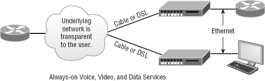
Both DSL and cable high-speed Internet services are available to millions of residential and business consumers worldwide, but in some areas, only one and sometimes neither service is available. Surprisingly, some of the differences between DSL and cable modem have nothing to do with the actual technologies—it comes down to the individual ISP. All other things being equal, issues like cost, reliability, and quality of customer support for both installation and maintenance really do vary significantly from one provider to the next.
DSL Technology and xDSL
DSL is not a complete end-to-end solution. It is really a physical layer transmission technology like dial-up, cable, or wireless. DSL connections are deployed in the last mile of a local telephone network or local loop. The term last mile has been used quite a bit in the last few years with broadband-type connections. It basically means the same thing as local loop, and defines the physical connection from the customer to the first aggregation device of the provider network.
A DSL connection is set up between a pair of modems on either end of a copper wire that is between the CPE and the digital subscriber line access multiplexer (DSLAM). A DSLAM is the device located at the provider's CO that concentrates connections from multiple DSL subscribers.
xDSL is really a family of technologies that have become popular for data transmission over phone lines because xDSL uses regular PSTN phone wires to transmit digital signals and is extremely inexpensive compared with other digital communications methods. The x in xDSL represents the various letters that refer to different DSL flavors. xDSLs use high-frequency signals, whereas regular phone calls use low-frequency signals over the same lines.
Communicating via xDSL requires an interface to a PC. All xDSL configurations require a DSL modem called an endpoint and a Network Interface Card (NIC) in your computer. The NIC can be connected directly to the DSL modem using a straight-through Ethernet UTP patch cord with standard RJ-45 connectors on each end. But if there are other connecting devices between the computer and the cable modem, you'll need either a special switchable port or an Ethernet crossover cable for things to work out well.
So Are These Really Modems?
Actually, neither ISDN nor cable modems are actually modems in the sense that no analog-to-digital signal modulation is occurring. But the industry calls them modems anyway!
A nice feature of xDSL implementations is that they cost tens of dollars instead of the hundreds, sometimes up to the thousands, you would have to pony up for a dedicated, digital point-to-point link like a T1. These cost-effective implementations include the following:
High Bit-Rate Digital Subscriber Line (HDSL) HDSL was the first DSL technology to use a higher-frequency spectrum of copper twisted-pair cables. HDSL was developed in the United States as a better technology for high-speed, synchronous circuits. It was typically used to interconnect local-exchange carrier systems and to carry high-speed corporate data links and voice channels using T1 lines.
Symmetric Digital Subscriber Line (SDSL) Symmetric (meaning same rate in both directions) digital subscriber line (SDSL) provides T1/E1 type speeds symmetrically for both uploading and downloading data, but doesn't allow low-frequency phone calls on the same line as asymmetric digital subscriber line (ADSL) does. How much it will set you back ranges between the cost of ADSL and T1s. This option is typically used by small to medium-sized businesses that don't require the higher performance of a leased line for connecting to a server.
Very High Bit-Rate Digital Subscriber Line (VDSL) VDSL, or very high bit-rate DSL (VHDSL), provides faster data transmission over single, flat, untwisted or twisted pairs of copper wires. This capacity for blazingly fast speeds mean that VDSL is capable of supporting high-bandwidth applications like HDTV and telephone services like the ever popular Voice over IP (VoIP) as well as general Internet access over a single connection. VDSL is deployed over existing wiring used for POTS and lower-speed DSL connections. Second-generation VDSL2 systems utilize bandwidths of up to 30MHz to provide data rates exceeding 100Mbps simultaneously in both the upstream and downstream directions. The maximum available bit rate is achieved at a range of about 300 meters with the signal performance degrading as the loop attenuation increases.
Asymmetric digital subscriber line (ADSL) Asymmetric (meaning different upload and download speed) DSL has become the most popular xDSL because it focuses on providing reasonably fast upstream transmission speeds (768Kbps) and very fast downstream transmission speeds of up to 9Mbps (ADSL2+ can get up to 20Mbps). This makes downloading graphics, audio, video, and data files from any remote computer a snap! The majority of web traffic is downstream. The best part is that ADSL works on a single phone line without losing voice call capability. This is accomplished with something called a splitter that enables the use of multiple frequencies on your POTS line.
Cable Modem
Cable is a great cost-effective connection for a small office or home office (SOHO)—yes, there is an acronym for everything. Even in larger organizations, cable, or even DSL, can be great to have around as a backup link.
Here are a few cable network terms:
Headend This is where all cable signals are received, processed, and formatted. The signals are then transmitted over the distribution network from the headend.
Distribution Network These are relatively small service areas that usually range in size from 100 to 2,000 customers. They're typically composed of a mixed, fiber-coaxial, or hybrid fiber-coaxial (HFC) architecture, with optical fiber substituting for the distribution network's trunk portion. The fiber forms both the connection from the headend and an optical node that changes light to radio frequency (RF) signals that are then distributed through a coaxial cable throughout the specific service area—that is, your home or office.
Data over Cable Service Interface Specifications (DOCSIS) This specification provides the interface requirements for a data-over-cable system, including that of high-speed data transfer to an existing cable TV system. All cable modems and similar devices have to measure up to this standard.
Figure 16.5 shows where you would be likely to find the various types of networks and how the terms I just listed would be used in a network diagram. The area on the right where coaxial cable is in use is the distribution network, and the box labeled Node is the optical node where light is converted to RF signals for use on the coaxial cable.

The problem with this is that ISPs often use a fiber-optic network that extends from the cable operator's master headend—sometimes even to regional headends—out to a neighborhood's hubsite and finally arrives at a fiber-optic node that services anywhere from 25 to 2,000 or more homes. I'm really not picking on cable, but here's another issue: If you have cable, open your PC's command prompt, type ipconfig, and check out your subnet mask. It's probably a /20 or /21 Class B address—yikes! You already know that translates to either 4,094 or 2,046 hosts per cable network connection—definitely not good.
When I say cable, I really mean using coax (coaxial) cable for transmission. Community antenna television (CATV) is now used as a means to offer cost-effective broadcasting to subscribers. Cable is able to provide voice and data, plus analog and digital video, without requiring your whole paycheck!
Your average cable connection gives you a maximum download speed of 20Mbps (theoretically, some providers sell this up to 50Mbps). And remember—you have to share that bandwidth with all the other subscribers. As if that weren't enough, there are other things like overloaded web servers and plain old network congestion that factor into the mix as well. But your email-checking neighbors really aren't making that much of a difference. So who or what is? Well, if you're an online gamer, you will likely notice a bit more lag during peak periods, which could be a matter of virtual life and death. And if somebody in your neighborhood is uploading a large amount of data, like, say, an entire collection of pirated Star Wars movies, it could definitely max out the entire connection and bring everyone's browser to crawl speed or worse.
Cable-modem access may or may not be faster or easier to install than DSL, and your mileage will vary, depending on where you live plus a variety of other factors. But it's usually more available and a tad less pricey, making it a winner by a nose. But no worries, if cable access isn't available in your neighborhood, DSL is okay—anything is better than dial-up!
Metro Ethernet
Metropolitan-area Ethernet is a metropolitan area network (MAN) that's based on Ethernet standards and can connect a customer to a larger network and the Internet.
If available, businesses can use Metro Ethernet to connect their offices together, which presents another very cost-effective connection option. MPLS-based Metro Ethernet networks use MPLS in the ISP by providing an Ethernet or fiber cable to the customer as a connection. From the customer, it leaves the Ethernet cable, jumps onto MPLS, and then Ethernet again on the remote side. This is a smart and thrifty solution that's very popular if you can get it in your area.
Wireless WAN Technologies
At one time, it was taken as gospel that wireless technologies, especially WAN technologies, could never be completely acceptable, especially when compared to terrestrial technologies. Today, that given is being challenged with a number of new technologies that can provide acceptable Internet and even multimedia performance without a landline. In the following sections, we'll look at some of the cellular WAN technologies and see how far we've really come in this regard.
Cellular WAN
Cellular technologies have evolved since their introduction in the late 1970s. Terms like 1G (first generation) 2G, 3G, and 4G are often used to describe significant advances in the technology. First I'll first give you a quick overview of the major developments, and then we'll look more closely at a couple of the newer technologies, specifically what these technologies bring to the table and what they may promise for the future.
First generation cellular (1G) was a voice-only analog network. The second generation (2G) marked the switch to digital, which allowed voice and, for the first time, simple data, such as a text message. Fourth generation (4G) is still the most widely used globally at this writing, but things change quickly. 4G allows high-speed voice and data, even Internet. This is the type of network supporting most of your smartphones.
GSM, or Global System for Mobile Communications, is a standard developed by the European Telecommunications Standards Institute (ETSI). It delineates protocols for 2G digital cellular networks, which are used by mobile phones, and it's the default global standard for mobile communications and enjoys over 90 percent market share. 2G is available in over 219 countries and territories worldwide.
The GSM standard was created to replace first generation (1G) analog cellular networks and originally described a digital, circuit-switched network optimized for full duplex voice telephony. It evolved to include data communications, at first via circuit-switched transport, then through packet data transport via General Packet Radio Services (GPRS) and EDGE, alternately via Enhanced Data rates for GSM Evolution (EGPRS).
Code division multiple access (CDMA) is a channel access method that's used by various radio communication technologies. CDMA offers multiple access, where several transmitters can send information simultaneously over a single communication channel, allowing several users to share a band of frequencies. To make this work without a bunch of interference between users, CDMA relies upon spread-spectrum technology and a special coding scheme in which each transmitter is assigned a unique code.
Fourth generation (4G) is actually still an emerging technology that has two variants, LTE and WiMAX. An organization called the Third Generation Partnership Project 2 (3GPP2) has set specific requirements that must be met for a system to call itself 4G. At this point in time, LTE and WiMAX meet these requirements.
The goal of 4G is to provide data rates way beyond what's typically available today. Even so, uplinks from the mobile device to the tower will always be much slower, and actual performance in the real world still isn't always so hot. I'll provide a few figures to clarify all this, but just know that 4G systems really should still be backward compatible with 3G systems most of the time to fully achieve the performance goals that 4G was created to meet. Oh, and obviously, the device itself has got to be 4G capable to start with!
HSPA+
Evolved High Speed Packet Access (HSPA+) is really considered a 3.5 generation technology. It does include an optional all-IP architecture, which is one of 4G's requirements, and it actually has greatly improved data rates over its HSPA forerunner. Because HSPA+ uses an all-IP architecture, it has the potential to evolve into a true 4G technology someday. It has downlink speeds of 3Mbps to 4Mbps and uplink speeds of 1Mbps to 2Mbps.
WiMAX
World Wide Interoperability for Microwave Access (WiMax) is considered a true 4G technology, and it's based on the IEEE 802.16 standard. It supports both fixed, tower-to-tower applications and mobile applications. It was originally designed as a last-mile technology to deliver Internet to areas where implementing landlines wasn't possible as an alternative to DSL and cable.
But it has its challenges too—WiMAX just isn't compatible with 2G and 3G technologies, and it's pricey and requires lots of power. Worse, it also lags behind LTE in speed with downlink speeds of 5Mbps to 6Mbps and uplink speeds of 2Mbps to 3Mbps.
LTE
This brings us to Long Term Evolution (LTE), which is definitely the most promising of all emerging 4G technologies. It uses an all-IP-based core, it offers the highest data rates, and it's compatible with 3G and WiMAX! And it happens to have the best indoor coverage while maintaining high data rates all the way to the edge of a coverage cell. If that isn't enough for you, it also accommodates more devices in a given area and still performs really well by maintaining data rates of 7Mbps to 12Mbps on the downlink and 3Mbps to 5Mbps on the uplink.
WAN Protocols
We'll be focusing on these six technologies in the following sections:
- ISDN
- Frame Relay
- PPP
- ATM
- MPLS
Integrated Services Digital Network
ISDN is a digital, point-to-point WAN technology capable of maximum transmission speeds of about 2Mbps (Primary Rate Interface [PRI]), although speeds of 128 Kbps (Basic Rate Interface [BRI]) are more the reality within a SOHO environment.
Because it's capable of much higher data rates at a relatively low cost, ISDN is becoming a viable remote-user connection method—especially for those who work out of their homes. ISDN uses the same UTP wiring as POTS, yet it can transmit data at much higher speeds. But that's where the similarity ends. The main thing that makes ISDN different from a regular POTS line is how it utilizes the copper wiring. Instead of carrying an analog voice signal, it carries digital signals, which also happens to be the key behind several more vital differences.
First, a computer connects to the 128Kbps ISDN line via an ISDN terminal adapter (TA) that's often incorrectly referred to as an ISDN modem. An ISDN TA is not a modem because it doesn't convert a digital signal from the computer to an analog signal on the subscriber line—ISDN signals are digital on the subscriber line. A TA is technically an ISDN-compatible device that has one or more non-ISDN ports for devices like computer serial interfaces and RJ-11 analog phones, which work to give these non-ISDN devices access to the ISDN network.
Second, an ISDN line has two types of channels. The data is carried on special Bearer channels, or B channels, each of which can carry 64Kbps of data. A BRI ISDN line has 2 B channels, and a PRI has 23 64Kbps channels. One channel can be used for a voice call while the other can be used for data transmissions, and it's all made possible by time-division multiplexing (TDM) on one pair of copper wires.
The other type of channel in ISDN is also multiplexed onto only one copper pair. It's used for call setup and link management and is known as the signaling channel, D channel, or Delta channel. This channel has only 16Kbps of bandwidth in BRI and 64Kbps in PRI.
To maximize throughput, the two B channels are often combined into one data connection for a total bandwidth of 128Kbps. This is known as Bandwidth on Demand Interoperability Group (BONDING) or inverse multiplexing.
But this still leaves the D channel free for signaling purposes. In rare cases, you may see user data, such as credit-card verification, on the D channel. This was introduced as an additional feature of ISDN, but it hasn't really caught on.
Some of the main advantages of ISDN are as follows:
- A fast connection.
- It offers higher bandwidth than POTS. BONDING yields 128Kbps bandwidth.
- There is no conversion from digital to analog.
ISDN has the following disadvantages:
- It's more expensive than POTS.
- Specialized equipment is required both at the phone company and at the remote computer.
- ISDN equipment isn't compatible to connect to every other type of equipment out there.
- Why use ISDN if you can get DSL or cable?
- It's just a plain outdated technology
Remember that ISDN is a type of dial-up connection that must be initiated.
So, you now know that ISDN is another form of high-speed Internet access that delivers digital services (on 64Kbps channels) over conditioned telephone copper pairs. As I mentioned earlier, the device you must hook up to your computer to access ISDN services is properly known as an ISDN terminal adapter, which doesn't change from digital to analog like a modem does. It's only capable of changing between digital transmission formats.
The box itself is about the size of a modem and happens to look pretty similar to one. And also like DSL modems, it has a phone jack and an Ethernet jack. You connect a phone cord from the phone jack to the wall jack where your ISDN services are being delivered, and then you connect an Ethernet cable from your PC to the ISDN TA's Ethernet jack. Older, less-capable TAs used an Electronic Industries Association/Telecommunications Industry Alliance (EIA/TIA) 232 serial port for PC connectivity. It's exactly these similarities that cause people to confuse ISDN TAs with standard modems.
Frame Relay Technology
Frame Relay is a WAN technology in which variable-length packets are transmitted by switching. Packet switching involves breaking messages into chunks at the sending device. Each packet can be sent over any number of routes on its way to its destination. The packets are then reassembled in the correct order at the receiving device. Because they are packet-switched and the exact path is unknown, we use a cloud when creating diagrams to illustrate how data travels throughout this type of service.
From everything you've learned so far, just telling you that Frame Relay is a packet-switched technology should make you immediately realize a couple of things about it:
- Frame Relay doesn't work like a point-to-point leased line (although it can be made to look and act like one).
- Frame Relay is usually less expensive than leased lines are, but there are some sacrifices to make to get that savings.
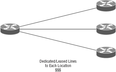
So, why would you even consider using Frame Relay? Take a look at Figure 16.6 to get an idea of what a network looked like before Frame Relay.
Now check out Figure 16.7. You can see that there's now only one connection between the corporate router and the Frame Relay switch. That saves some major cash.
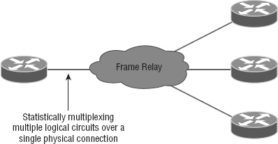
Let's say you need to add seven remote sites to the corporate office and you have only one free serial port on your router. Frame Relay to the rescue! Of course, I should probably mention that you now also have one single point of failure, which is not so good. But Frame Relay is used to save money, not to make a network more resilient.
Coming up, I'm going to cover the Frame Relay technology information you need to know about when studying for the CompTIA Network+ exam.
Committed Information Rate
Frame Relay allows for a packet-switched network to be provided to many different customers at the same time. This is really good because it spreads out the cost of the switches among lots of customers. But remember, Frame Relay is based on the assumption that all customers won't need to transmit data constantly—or even all at the same time.
Frame Relay works by providing a portion of dedicated bandwidth to each user, and it also allows the user to exceed their guaranteed bandwidth if resources on the telco network happen to be available. So basically, Frame Relay providers allow customers to buy a lower amount of bandwidth than they really use. There are two separate bandwidth specifications with Frame Relay:
Access Rate The maximum speed at which the Frame Relay interface can transmit.
Committed Information Rate (CIR) The maximum bandwidth of data guaranteed to be delivered. In reality, it's the average amount that the service provider will allow you to transmit, based upon what you purchased.
If these two values are the same, the Frame Relay connection is pretty much just like a leased line. But they can actually be set to different values. Here's an example: Let's say that you buy an access rate of T1 (1.544Mbps) and a CIR of 256Kbps. By doing this, you're guaranteed that the first 256Kbps of traffic you send will be delivered. Anything beyond that is called a burst—a transmission that exceeds your guaranteed 256Kbps rate and can total any amount up to the T1 access rate, if that amount is permitted in your contract. If your combined committed burst, which is the basis for your CIR, and excess burst sizes, known as the maximum burst rate (MBR), exceed the access rate, you can pretty much say goodbye to your additional traffic because it will most likely be dropped! Whether this happens or not basically comes down to the subscription level offered by a particular service provider.
In a perfect world, this always works beautifully—but remember that little word guarantee—as in guaranteed rate, of 256Kbps to be exact? This means any burst of data you send that exceeds your guaranteed 256Kbps rate will be delivered on something called a “best effort” delivery basis. Or maybe not—if your telco's equipment doesn't have the capacity to deliver it at the time you transmitted, then your frames will be discarded and the DTE will be notified. Timing is everything—you can scream data out at six times your guaranteed rate of 256Kbps (T1) only if your telco has the capacity available on its equipment at that moment!
Virtual Circuits
Frame Relay operates using virtual circuits as opposed to the actual circuits that leased lines use. These virtual circuits are what link together the thousands of devices connected to the provider's “cloud.” Frame Relay provides a virtual circuit between your two DTE devices, making them appear to be connected via a circuit when in reality they're dumping their frames into a large, shared infrastructure. You never see the complexity of what's actually happening inside the cloud because you only have a virtual circuit.
And on top of all that, there are two types of virtual circuits—permanent and switched. Permanent virtual circuits (PVCs) are by far the most common type in use today. What permanent means here is that the telco creates the mappings inside its gear and as long as you pay the bill, they'll remain “permanently” in place.
Switched virtual circuits (SVCs) are more like phone calls. The virtual circuit is established when data needs to be transmitted, and it's taken down when the data transfer is complete.
I have never seen a Frame Relay service using SVCs offered by a telco in North America. It's used mainly in private Frame Relay networks.
Data Link Connection Identifiers
Frame Relay PVCs are identified to DTE end devices by Data Link Connection Identifiers (DLCIs). A Frame Relay service provider typically assigns DLCI values, which are used on Frame Relay interfaces to distinguish between different virtual circuits. Because many virtual circuits can be terminated on one multipoint Frame Relay interface, many DLCIs are often affiliated with it.
Let me explain. Suppose you have a central HQ with three branch offices. If you were to connect each branch office to HQ using a T1, you would need three serial interfaces on your router at HQ, one for each T1. Simple, right? Well, suppose you use Frame Relay PVCs instead. You could have a T1 at each branch connected to a service provider and only a single T1 at HQ. There would be three PVCs on the single T1 at HQ, one going to each branch. And even though you'd have only a single interface and a single CSU/DSU, the three PVCs would function as three separate circuits. Remember what I said about saving money? How much for two additional T1 interfaces and a pair of CSU/DSUs? Answer: A lot! So, why not go ahead and ask for a percentage of the savings in your bonus?
Point-to-Point Protocol
Point-to-Point Protocol (PPP) is a Data Link layer protocol that can be used over either asynchronous serial (dial-up) or synchronous serial (ISDN) media. It relies on Link Control Protocol (LCP) to build and maintain data-link connections. Network Control Protocol (NCP) enables multiple Network layer protocols (routed protocols) to be used on a point-to-point connection.
Because HDLC is the default serial encapsulation on Cisco serial links and it works great, why in the world would you choose to use PPP? Well, the basic purpose of PPP is to transport Layer 3 packets across a Data Link layer point-to-point link, and it's nonproprietary. So unless you have all Cisco routers, you need PPP on your serial interfaces because the HDLC encapsulation is Cisco proprietary, remember? Plus, since PPP can encapsulate several Layer 3 routed protocols and provide authentication, dynamic addressing, and callback, PPP could actually be the best encapsulation solution for you over HDLC anyway.
Figure 16.8 shows the PPP stack compared to the OSI reference model.
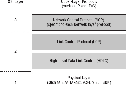
PPP contains four main components:
EIA/TIA-232-C, V.24, V.35, and ISDN A Physical layer international standard for serial communication.
HDLC A method for encapsulating datagrams over serial links.
LCP A method of establishing, configuring, maintaining, and terminating the point-to-point connection. It also provides features such as authentication. I'll give you a complete list of these features coming up soon in the next section.
NCP A method of establishing and configuring different Network layer protocols for transport across the PPP link. NCP is designed to allow the simultaneous use of multiple Network layer protocols. Two examples of protocols here are Internet Protocol Control Protocol (IPCP) and Cisco Discovery Protocol Control Protocol (CDPCP).
Burn it into your mind that the PPP protocol stack is specified at the Physical and Data Link layers only. NCP is used to allow communication of multiple Network layer protocols by identifying and encapsulating the protocols across a PPP data link.
Next, we'll cover the options for LCP and PPP session establishment.
Link Control Protocol (LCP) Configuration Options
Link Control Protocol (LCP) offers different PPP encapsulation options, including the following:
Authentication This option tells the calling side of the link to send information that can identify the user. The two methods for this task are PAP and CHAP.
Compression This is used to increase the throughput of PPP connections by compressing the data or payload prior to transmission. PPP decompresses the data frame on the receiving end.
Error Detection PPP uses Quality and Magic Number options to ensure a reliable, loop-free data link.
Multilink The multilink option makes several separate physical paths appear to be one logical path at Layer 3. This means that the two T1s running multilink PPP would show up as a single 3Mbps path to a Layer 3 routing protocol.
PPP Callback On a dial-up connection, PPP can be configured to call back after successful authentication. PPP callback can be a very good thing because it allows us to keep track of usage based upon access charges for accounting records and a bunch of other reasons. With callback enabled, a calling router (client) will contact a remote router (server) and authenticate. Predictably, both routers have to be configured for the callback feature for this to work. Once authentication is completed, the remote router will terminate the connection and then reinitiate a connection to the calling router.
PPP Session Establishment
When PPP connections are started, the links go through three phases of session establishment, as shown in Figure 16.9:
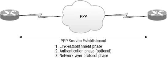
Link-Establishment Phase LCP packets are sent by each PPP device to configure and test the link. These packets contain a field called Configuration Option that allows each device to see the size of the data, the compression, and authentication. If no Configuration Option field is present, then the default configurations will be used.
Authentication Phase If required, either CHAP or PAP can be used to authenticate a link. Authentication takes place before Network layer protocol information is read, and it's also possible that link-quality determination will occur simultaneously.
Network Layer Protocol Phase PPP uses the Network Control Protocol (NCP) to allow multiple Network layer protocols to be encapsulated and sent over a PPP data link.
Each Network layer protocol (e.g., IP, IPv6, which are routed protocols) establishes a service with NCP.
PPP Authentication Methods
There are two methods of authentication that can be used with PPP links:
Password Authentication Protocol (PAP) Password Authentication Protocol (PAP) is the less secure of the two methods. Passwords are sent in clear text and PAP is performed only upon the initial link establishment. When the PPP link is first established, the remote node sends the username and password back to the originating target router until authentication is acknowledged. Not exactly Fort Knox!
Challenge Handshake Authentication Protocol (CHAP) The Challenge Handshake Authentication Protocol (CHAP) is used at the initial startup of a link and at periodic checkups on the link to ensure that the router is still communicating with the same host. After PPP finishes its initial link-establishment phase, the local router sends a challenge request to the remote device. The remote device sends a value calculated using a one-way hash function called MD5. The local router checks this hash value to make sure it matches. If the values don't match, the link is immediately terminated.
CHAP authenticates at the beginning of the session and periodically throughout the session.
Asynchronous Transfer Mode
Asynchronous Transfer Mode (ATM), not to be confused with automated teller machines, first emerged in the early 1990s. ATM was designed to be a high-speed communications protocol that doesn't depend on any specific LAN topology. It uses a high-speed cell-switching technology that can handle data as well as real-time voice and video. The ATM protocol breaks up transmitted data into 53-byte cells. A cell is analogous to a packet or frame, except that an ATM cell is always fixed in length and is relatively small and fast, whereas a frame's length can vary.
ATM is designed to switch these small cells through an ATM network very quickly. It does this by setting up a virtual connection between the source and destination nodes; the cells may go through multiple switching points before ultimately arriving at their final destination. The cells may also arrive out of order, so the receiving system may have to reassemble and correctly order the arriving cells. ATM, like Frame Relay, is a connection-oriented service, in contrast to most Data Link protocols, which are best-efforts delivery services and do not require virtual circuits to be established before transmitting user data.
Data rates are scalable and start as low as 1.5Mbps, with speeds of 25Mbps, 51Mbps, 100Mbps, 155Mbps, and higher. The common speeds of ATM networks today are 51.84Mbps and 155.52Mbps; both of them can be used over either copper or fiber-optic cabling. You can also get ATM with a speed of 622.08Mbps, but that is currently used exclusively over fiber-optic cable. ATM supports very high speeds because it's designed to be routed by hardware rather than software, which makes faster processing speeds possible.
Fiber-based service-provider ATM networks are running today at data rates of 10Gbps, and they're becoming more and more common. These fast speeds make real-time payloads like voice and video travel with data on an ATM network and arrive without too much delay, or latency. The small size of the payload, compared to the size of each cell's header, makes ATM less efficient than other WAN technologies. In other words, ATM networks are fast, but they get bad gas mileage.
MPLS
MultiProtocol Label Switching (MPLS) is a data-carrying mechanism that emulates some properties of a circuit-switched network over a packet-switched network. So MPLS is a actually a switching mechanism that imposes labels (numbers) to packets and then uses them to forward packets. The labels are assigned on the edge of the MPLS network, and forwarding inside the MPLS network is carried out solely based on the labels. The labels usually correspond to a path to Layer 3 destination addresses, which is on par with IP destination-based routing. MPLS was designed to support the forwarding of protocols other than TCP/IP. Because of this, label switching within the network is achieved the same way irrespective of the Layer 3 protocol. In larger networks, the result of MPLS labeling is that only the edge routers perform a routing lookup. All the core routers forward packets based on the labels, which makes forwarding the packets through the service provider network faster. This is a big reason most companies have replaced their Frame Relay networks with MPLS service today. Last, you can use Ethernet with MPLS to connect a WAN, and this is called Ethernet over MPLS, or EoMPLS.
WAN Troubleshooting
Troubleshooting WANs can be tough at times because you don't control and own the physical lines. You definitely do receive the trouble tickets and stressful emails, but you're relying on someone else to do their job, and you have limited visibility in a lot of areas. However, that doesn't mean you're powerless, but it does mean that you've got to narrow the problem down to make sure you're working on the correct issue.
Loss of Internet Connectivity
The most common trouble ticket you'll receive is someone complaining about not being able to connect to the Internet. This issue can be caused by the WAN link dropping the CSU/DSU or internal wiring, but most of the time, it's due to an ISP issue. This doesn't mean you don't need to check your local physical WAN connections though. A better approach is to double check all your power to all devices, including the smart jack, and run a loopback test from the router to the CSU/DSU to verify that specific links come up locally. Figure 16.10 shows the different spots you would typically need to check out.

One more thing—if you have either a copper line driver or repeaters in your WAN link, you've got to be sure to check those connections too!
Interface Errors/Monitoring
There are a couple of key interfaces you need to check when verifying your WAN. If you have cable or DSL, you'll need to check into interface errors on the LAN port connecting to your router first. Let's take a look at an example to clarify how to use this information for interface monitoring to scrutinize errors, utilization, discards, packet drops, interface resets, and duplex issues:
Router#sh int fa0/0
FastEthernet0/0 is up, line protocol is up
[output cut]
  Full-duplex, 100Mb/s, 100BaseTX/FX
  ARP type: ARPA, ARP Timeout 04:00:00
  Last input 00:00:05, output 00:00:01, output hang never
  Last clearing of “show interface” counters never
  Input queue: 0/75/0/0 (size/max/drops/flushes); Total output drops: 0
  Queueing strategy: fifo
  Output queue: 0/40 (size/max)
  5 minute input rate 0 bits/sec, 0 packets/sec
  5 minute output rate 0 bits/sec, 0 packets/sec
     1325 packets input, 157823 bytes
     Received 1157 broadcasts (0 IP multicasts)
     0 runts, 0 giants, 0 throttles
     0 input errors, 0 CRC, 0 frame, 0 overrun, 0 ignored
     0 watchdog
     0 input packets with dribble condition detected
     2294 packets output, 244630 bytes, 0 underruns
     0 output errors, 0 collisions, 3 interface resets
     347 unknown protocol drops
     0 babbles, 0 late collision, 0 deferred
     4 lost carrier, 0 no carrier
     0 output buffer failures, 0 output buffers swapped out
Link Status The first thing we'll check when there is a trouble ticket or our network management tools alert us of a link error is the link status. This is the first line in the output as shown. This would be the same on serial links as is it on Ethernet links.
Router#sh int fa0/0
FastEthernet0/0 is up, line protocol is up
The first up listed is carrier detect. If this shows down, then you have a physical layer problem locally and you need to get to that port stat and check the cable and port. The second statistic, which is protocol is up in this example, is keepalives from the remote end. If you see up/down, then you know your local end is good but you're not getting a digital signal from the remote end.
You've got to be able to analyze interface statistics to find problems there if they exist, so let's pick out the important factors relevant to meeting that challenge effectively now:
Speed and Duplex Settings Make a mental note that the most common cause of interface errors is a mismatched duplex mode between two ends of an Ethernet link. This is why it's so vital to verify that the switch and its hosts—PCs, router interfaces, cable modems, and so on—all have the same speed setting. If they don't, they just won't connect. And if they have mismatched duplex settings, you'll receive a legion of errors, which cause nasty performance issues, intermittent connectivity, and sometimes even a total loss of communication!
A common strategy is to use autonegotiation for speed and duplex, and it's enabled by default. But if this fails for some reason, you'll have to set the configuration manually like this:
Router(config)#int gi0/1
Router(config-if)#speed ?
  10    Force 10 Mbps operation
  100   Force 100 Mbps operation
  1000  Force 1000 Mbps operation
  auto  Enable AUTO speed configuration
Router(config-if)#speed 1000
Router(config-if)#duplex ?
  auto Enable AUTO duplex configuration
  full Force full duplex operation
  half  Force half-duplex operation
Router(config-if)#duplex  full
If you have a duplex mismatch, a telling sign is that the late collision counter will increment.
Input Queue Drops If the input queue drops counter increments, this tells you that more traffic is being delivered to the router than it can process. If this value is consistently high, try to determine exactly when these counters are increasing and how the events relate to CPU usage. Know that you'll see the ignored and throttle counters increment as well.
Output Queue Drops This counter indicates that packets were dropped due to interface congestion, leading to lost data and queuing delays. When this occurs, applications like VoIP will experience performance issues. If you observe this constantly incrementing, consider QoS as the culprit.
Input Errors Input errors often indicate high-level errors such as CRCs. This can point to cabling problems, hardware issues, or duplex mismatches.
Output Errors This issue equals the total number of frames that the port tried to transmit when an issue such as a collision occurred.
These errors can also be caused by interference of the line itself, which means you'll have to call the ISP to sort them out.
On serial interface, start by checking out the physical connection to your router. Are you receiving clocking? This comes from the CSU/DSU. Check out the output to see how to do that:
Router>sh controllers s0/0
Interface Serial0/0
Hardware is PowerQUICC MPC860
DTE V.35 TX and RX clocks detected.
Okay, we've verified we're receiving clocking, so let's move on to look at the what the interface is telling us:
Router#sh int s0/0
Serial0/0 is up, line protocol is down
  Hardware is PowerQUICC Serial
  Description: Connection to CR1
  Internet address is 192.168.11.1/24
  MTU 1500 bytes, BW 1000 Kbit, DLY 20000 usec,
    reliability 255/255, txload 1/255, rxload 1/255
  Encapsulation PPP, LCP Closed, loopback not set
  Keepalive set (10 sec)
  CRC checking enabled
  Last input never, output never, output hang never
  Last clearing of “show interface” counters 00:02:58
  Input queue: 0/75/0/0 (size/max/drops/flushes); Total output drops: 0
  Queueing strategy: fifo
  Output queue: 0/40 (size/max)
  5 minute input rate 0 bits/sec, 0 packets/sec
  5 minute output rate 0 bits/sec, 0 packets/sec
     0 packets input, 0 bytes, 0 no buffer
     Received 0 broadcasts, 0 runts, 0 giants, 0 throttles
    1565789 input errors, 0 CRC, 0 frame, 0 overrun, 0 ignored, 0 abort
     0 packets output, 0 bytes, 0 underruns
     0 output errors, 0 collisions, 2 interface resets
     0 output buffer failures, 0 output buffers swapped out
     0 carrier transitions
     DCD=up  DSR=up  DTR=up  RTS=up  CTS=up

BR1#
See that? We can see a problem with this interface right there in the first line output. The Serial0/0 is up, but the line protocol is down, which tells us that our local router interface connecting to the CSU/DSU is working, but we're still not seeing the remote router. Once in a while this indicates a remote router problem, but it's usually an ISP issue. So again, it means you've got to call into the ISP if you're getting this error. And look at all those input errors! This is screaming that you've got a troubled line—probably some type of interference, which needs to be reported.
Split Horizon
Split horizon issues usually happen when using Frame Relay in an environment where you have multiple PVCs coming into a single serial WAN interface. This configuration makes the routing protocol think that it's receiving routes on the same interface that they were being sent out of, which in this case would result in the routes being dropped. A great way to solve this problem is to create subinterfaces (logical interfaces) on the serial interface to make the routing protocol believe there are multiple interfaces—one for each subnet—so the routing advertisement will be received. The configuration would go from looking like this:
interface Serial0/0
 ip address 10.1.12.1 255.255.255.0
 no ip directed-broadcast
 encapsulation frame-relay
to looking like this:
interface Serial0/0
 no ip address (notice there is no IP address on the physical interface!)
 no ip directed-broadcast
 encapsulation frame-relay
!
interface Serial0/0.102 point-to-point
 ip address 10.1.12.1 255.255.255.0
 no ip directed-broadcast
frame-relay interface-dlci 102
!
interface Serial0/0.103 point-to-point
 ip address 10.1.13.1 255.255.255.0
 no ip directed-broadcast
frame-relay interface-dlci 103
!
DNS Issues
Another issue that could make it appear as if the Internet connectivity has gone down completely involves DNS. If users cannot resolve names, it seems like everything is broken to them. The first step to solving a DNS issue is to understand exactly how your DNS is set up on your specific network. Do you have a local DNS server or are you using the ISP's DNS server? If you can ping a site, such as 74.125.228.50, but can't ping www.google.com from an internal host, you know you're dealing with a DNS resolution issue. Start by verifying the local DNS server, if you use one, and if that checks out, call the ISP.
Router Configurations
Router configurations can also be the culprit when WAN services just aren't working right. All you need is an admin that enters some routing protocol information incorrectly and your access to the Internet goes poof! So your first step is always to verify your default route to the ISP when troubleshooting the routers that connect you to the Internet.
By using the command show ip route on a router, we can see the routing table—a map of the internetwork that the router uses to make its forwarding decisions:
Router#sh ip route
Codes: L - local, C - connected, S - static,
[output cut]
        10.0.0.0/8 is variably subnetted, 6 subnets, 4 masks
C       10.0.0.0/8 is directly connected, FastEthernet0/3
L       10.0.0.1/32 is directly connected, FastEthernet0/3
C       10.10.0.0/16 is directly connected, FastEthernet0/2
L       10.10.0.1/32 is directly connected, FastEthernet0/2
C       10.10.10.0/24 is directly connected, FastEthernet0/1
L       10.10.10.1/32 is directly connected, FastEthernet0/1
S*      0.0.0.0/0 is directly connected, FastEthernet0/0
Verify the default route, which is the one that starts with an S*. If this route points to the wrong next hop or wrong exit interface, you're going to have some serious problems!
Company Security Policy
Another common culprit that can often cause WAN-related problems is the company security policy. For example, if there's a firewall blocking ports, say, on applications that need to get to the Internet, it mimics a WAN issue when the root of the problem is actually bad configuration on your firewall(s)!
Another common source of trouble tickets have to do with slow response time, which again can make it look as though it's the WAN link that's having issues. But again, it's possible that it's the security policy that's throttling bandwidth on certain applications. I can't tell you how typical this is these days! Many company policies block certain sites, demanding that you provide URL filtering to them, especially social media or streaming news feeds. People often refer to these security-oriented limitations as fair access policies or utilization limits, which are forced upon certain activities for several reasons but most often to preserve bandwidth.
Summary
In this chapter, you learned about the important issues involved in providing WAN connectivity between geographically separated network locations as well as about the different kinds of WAN connections, including point-to-point connections, circuit-switched service provider networks, and packet-switched service provider networks.
You also became aware of the impacts different transmission media and different distance parameters have on WAN connections. In addition, you learned about the choices for leased-line connections along with broadband technologies like xDSL and cable modems.
You studied the different WAN protocols and technologies used in connecting today's high-speed WANs, including ISDN, Frame Relay, ATM, and MPLS, and were equipped with helpful strategies to troubleshoot and solve common WAN connection issues.
Exam Essentials
Be able to differentiate the kinds of WAN technologies. You must be able to identify the speeds and capacities of the different remote-access and WAN technologies as well as the media over which they are implemented.
Identify the basic characteristics of various Internet access technologies. These include DSL, broadband cable, POTS, and fiber to the premises (PON). It is important to know the differentiating features of these access technologies. Know their advantages and disadvantages so you can identify the best use of each.
Be knowledgeable about the differences between circuit-switched and packet-switched technologies, and know which protocols use either. Frame Relay is a packet-switched technology, and ISDN is a circuit-switched digital solution. ATM is considered to be a cell-switched technology because it incorporates a 53-byte cell. Both MPLS and ATM are considered connection-oriented technologies because the connection is set up first.
Be clear about the differences involving speed and distance between different media and between different WAN protocols. The use of both wireless and fiber is growing, and their standards are facilitating faster speeds and coverage of greater distances.
Be able to differentiate cellular WAN technologies like HSPA+, WiMAX, and LTE. HSPA+ is considered 3.5G, while LTE and WiMAX are considered true 4G.
Be able to differentiate between the different WAN protocols and technologies, their relative costs and speeds, and the types of implementations for which each would serve as a best solution. ISDN is rarely used nowadays in its BRI configuration except for small home or office solutions. Frame Relay is relatively inexpensive, but service providers have overbooked their Frame Relay clouds, resulting in poor performance. ATM is fast but inefficient, and MPLS is fast and more efficient but complicated to administer.
Written Lab
You can find the answers in Appendix A.
- What is the greatest advantage of PSTN (POTS)?
- Which technology uses the term HFC?
- You have one serial port on your router but need to connect many remote sites. What WAN protocol could you consider as an option?
- What is the maximum speed for T1?
- What does the acronym DSL stand for?
- Which WAN technologies are considered packet-switching networks?
- Which cellular technologies are considered 4G?
- Which WAN technology is considered a cell-switching network?
- What are the different flavors of xDSL?
- What is another name for PON?
Review Questions
You can find the answers to the review questions in Appendix B.
- Which of the following is not a WAN protocol or technology?
- ATM
- ISDN
- MPLS
- RIP
- What OSI model layers do WAN protocols operate in?
- Layer 6, Layer 4, Layer 2
- Transport, Data Link, Network
- Physical, Data Link, Network
- Application, Data Link, Network
- If you have a device in a telecommunications closet owned and installed by the telecommunications company (telco) and it's your responsibility to cable from this box to the CPE, which term should you use to refer to the device?
- Customer premises equipment
- Demarcation point
- Toll network
- Central office
- You have an E1. How many DS0s are used in this point-to-point connection?
- 24
- 25
- 30
- 32
- Where does the local exchange carrier responsibility end and your responsibility begin on a WAN link?
- POP
- Central office
- Demarc
- Smart jack
- You have a small office/home office environment. What WAN technology would most likely be used?
- T1
- T3
- Frame Relay
- Cable modem
- Which type of communication has a line speed of 1.544Mbps (millions of bits per second)?
- T3
- T1C
- T1
- T4
- Which cellular WAN technology has the best data rate?
- HSPA
- HSPA+
- LTE
- WiMAX
- Which is not a common optical carrier level (OC-x)?
- OC-1
- OC-4
- OC-12
- OC-192
- Which wireless protocol utilizes a short-range communications technology facilitating data transmission from fixed and/or mobile devices, creating wireless personal area networks (PANs)?
- Bluetooth
- Microwave radio relay
- Comsat
- Point-to-multipoint
- What does the x in xDSL represent?
- Wire type
- Transmission speed
- DSL type
- Download speed
- Which is not a type of xDSL?
- What does the acronym DOCSIS stand for?
- Data over cable service interface spectrum
- Data over cable systems Internet specification
- Data over cable service Internet specification
- Data over cable service interface specification
- What is the bandwidth for OC-12?
- 1.544Mbps
- 45Mbps
- 622Mbps
- 1000Mbps
- Which WAN protocol utilizes cell-switching technology?
- Frame Relay
- ISDN
- ATM
- RIP
- Which WAN protocol utilizes packet-switched technology?
- Frame Relay
- ISDN
- ATM
- RIP
- What is the CIR in Frame Relay?
- Virtual circuit that is established when data needs to be transmitted
- Maximum speed at which the Frame Relay interface can transmit
- Rate at which the Frame Relay switch guarantees to transfer data
- Rate at which the Frame Relay switch agrees to receive data
- You are having DSL Internet connection issues and time-outs. You check the interface on your router and notice a lot of input errors. What could the problem be?
- CSU/DSU
- Demarc
- Duplex configuration
- Clocking is down
- Which WAN has a transfer rate of 44.7Mbps?
- How does DWDM put multiple transmissions on a single strand?
- Different frequencies
- Different polarizations
- Different wavelengths
- Different time slots