
Chapter 3
Networking Topologies, Connectors, and Wiring Standards
THE FOLLOWING COMPTIA NETWORK+ EXAM OBJECTIVES ARE COVERED IN THIS CHAPTER:
- 1.0 Network architecture
- 1.5 Install and properly terminate various cable types and connectors using appropriate tools
- Copper connectors
- RJ-11
- RJ-45
- RJ-48C
- DB-9/RS-232
- DB-25
- UTP coupler
- BNC coupler
- BNC
- F-connector
- 110 block
- 66 block
- Copper cables
- Fiber connectors
- ST
- SC
- LC
- MTRJ
- FC
- Fiber coupler
- Fiber cables
- Single mode
- Multimode
- APC vs UPC
- Media converters
- Single mode fiber Ethernet
- Multimode fiber Ethernet
- Fiber coaxial
- Single mode multimode fiber
- Copper connectors
- 4.8 Given a scenario, troubleshoot and resolve common WAN issues
- Customer premise equipment
- Smart jack/NIU
- Demarc
- CSU/DSU
- Customer premise equipment
- 5.0 Industry standards, practices, and network theory
- 5.4 Given a scenario, deploy the appropriate wired connectivity standard
- Wiring standards
- EIA/TIA 568A/568B
- Wiring standards

The idea of connecting a bunch of computers together hasn't changed a whole lot since the mid-1980s, but how we go about doing that certainly has. Like everything else, the technologies and devices we create our networks with have evolved dramatically and will continue to do so in order to keep up with the ever-quickening pace of life and the way we do business.
When you connect computers together to form a network, you want error-free, blazingly fast communication, right? Although “error-free” and reality don't exactly walk hand in hand, keeping lapses in communication to a minimum and making that communication happen really fast is definitely possible. But it isn't easy, and understanding the types of media and network topologies used in networking today will go far in equipping you to reach these goals. So will being really knowledgeable about the array of components and devices used to control network traffic.
All of these networking ingredients are going to be the focus of this chapter. In it, I'll cover different types of networking media, discuss common topologies and devices, and compare the features that they all bring into designing a solid network that's as problem free and turbo charged as possible.

To find up-to-the-minute updates for this chapter, please see www.lammle.com/networkplus or the book's website at http://sybextestbanks.wiley.com/.
Physical Media
A lot of us rely on wireless networking methods that work using technologies like radio frequency and infrared, but even wireless depends on a physical media backbone in place somewhere. And the majority of installed LANs today communicate via some kind of cabling, so let's take a look at the three types of popular cables used in modern networking designs:
- Coaxial
- Twisted-pair
- Fiber optic
Coaxial Cable
Coaxial cable, referred to as coax, contains a center conductor made of copper that's surrounded by a plastic jacket with a braided shield over it. A plastic such as polyvinyl chloride (PVC) or fluoroethylenepropylene (FEP, commonly known as Teflon) covers this metal shield. The Teflon-type covering is frequently referred to as a plenum-rated coating, and it's definitely expensive but often mandated by local or municipal fire code when cable is hidden in walls and ceilings. Plenum rating applies to all types of cabling and is an approved replacement for all other compositions of cable sheathing and insulation like PVC-based assemblies.
The difference between plenum and non-plenum cable comes down to how each is constructed and where you can use it. Many large multistory buildings are designed to circulate air through the spaces between the ceiling of one story and the floor of the next; this space between floors is referred to as the plenum. And it just happens to be a perfect spot to run all the cables that connect the legions of computers that live in the building. Unless there's a fire—if that happens, the non-plenum cable becomes a serious hazard because its insulation gives off poisonous smoke that gets circulated throughout the whole building. Plus, non-plenum cables can actually become “wicks” for the fire, helping it quickly spread from room to room and floor to floor—yikes!
Because it's a great goal to prevent towering infernos, the National Fire Protection Association (NFPA) demands that cables run within the plenum have been tested and guaranteed as safe. They must be fire retardant and create little or no smoke and poisonous gas when burned. This means you absolutely can't use a non-plenum-type cable in the plenum, but it doesn't mean you can't use it in other places where it's safe. And because it's a lot cheaper, you definitely want to use it where you can.
Thin Ethernet, also referred to as thinnet or 10Base2, is a thin coaxial cable. It is basically the same as thick coaxial cable except it's only about 5 mm, or 2/10" diameter coaxial cable. Thin Ethernet coaxial cable is Radio Grade 58, or just RG-58. Figure 3.1 shows an example of thinnet. This connector resembles the coaxial connector used for cable TV, which is called an F connector.

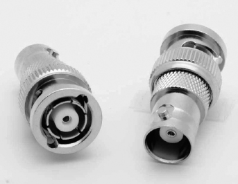
Oh, by the way, if you use thinnet cable, you've got to use BNC connectors to attach stations to the network, as shown in Figure 3.2, and you have to use 50 ohm terminating resistors at each end of the cable in order to achieve the proper performance.
You don't have to know much about most coax cable types in networks anymore, especially the thinnet and thicknet types of coaxial cable. Thicknet was known as RG-8, was about 1/2” in diameter, also requiring 50 ohm terminating resistors on each end of the cable. Nowadays, we use 75 ohm coax for cable TV; using coax in the Ethernet LAN world is pretty much a thing of the past, but we do use them for high-bandwidth runs in our data centers. RG-6, or CATV coax, is used in our broadband world.
You can attach a BNC connector to the cable with a crimper that looks like a weird pair of pliers and has a die to crimp the connector. A simple squeeze crimps the connector to the cable. You can also use a screw-on connector, but I avoid doing that because it's not very reliable.
You can use a BNC coupler to connect two male connectors together or two female connectors together.
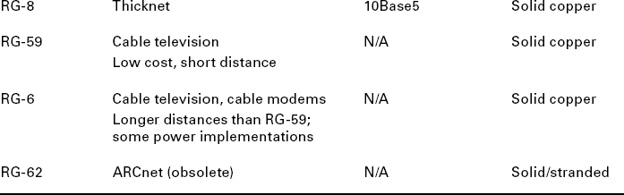
Table 3.1 lists some specifications for the different types of coaxial cable, but understand that we use only RG-59 and RG-6 in today's world.

An advantage of using coax cable is the braided shielding that provides resistance to electronic pollution like electromagnetic interference (EMI), radio frequency interference (RFI), and other types of stray electronic signals that can make their way onto a network cable and cause communication problems.
Twisted-Pair Cable
Twisted-pair cable consists of multiple individually insulated wires that are twisted together in pairs. Sometimes a metallic shield is placed around them, hence the name shielded twisted-pair (STP). Cable without outer shielding is called unshielded twisted-pair (UTP), and it's used in twisted-pair Ethernet (10BaseT, 100BaseTX, 1000BaseTX) networks.
Ethernet Cable Descriptions
Ethernet cable types are described using a code that follows this format: N<Signaling>X. The N refers to the signaling rate in megabits per second. <Signaling> stands for the signaling type—either baseband or broadband—and the X is a unique identifier for a specific Ethernet cabling scheme.
Here's a common example: 100BaseX. The 100 tells us that the transmission speed is 100Mb, or 100 megabits. The X value can mean several different things, for example, a T is short for twisted-pair. This is the standard for running 100-megabit Ethernet over two pairs (four wires) of Category 5, 5e, or 6 UTP.
So why are the wires in this cable type twisted? Because when electromagnetic signals are conducted on copper wires in close proximity—like inside a cable—it causes interference called crosstalk. Twisting two wires together as a pair minimizes interference and even protects against interference from outside sources. This cable type is the most common today for the following reasons:
- It's cheaper than other types of cabling.
- It's easy to work with.
- It allows transmission rates that were impossible 10 years ago.
UTP cable is rated in these categories:
Category 1 Two twisted wire pairs (four wires). It's the oldest type and is only voice grade—it isn't rated for data communication. People refer to it as plain old telephone service (POTS). Before 1983, this was the standard cable used throughout the North American telephone system. POTS cable still exists in parts of the Public Switched Telephone Network (PSTN) and supports signals limited to the 1MHz frequency range.
Category is often shortened to Cat. Today, any cable installed should be a minimum of Cat 5e because some cable is now certified to carry bandwidth signals of 350MHz or beyond. This allows unshielded twisted-pair cables to exceed speeds of 1Gbps—fast enough to carry broadcast-quality video over a network.
Category 2 Four twisted wire pairs (eight wires). It handles up to 4Mbps, with a frequency limitation of 10MHz, and is now obsolete.
Category 3 Four twisted wire pairs (eight wires) with three twists per foot. This type can handle transmissions up to 16MHz. It was popular in the mid-1980s for up to 10Mbps Ethernet, but it's now limited to telecommunication equipment and, again, is obsolete for networks.
Category 4 Four twisted wire pairs (eight wires), rated for 20MHz; also obsolete.
Category 5 Four twisted wire pairs (eight wires), rated for 100MHz. But why use Cat 5 when you can use Cat 5e for the same price? I am not sure you can even buy plain Cat 5 anymore!
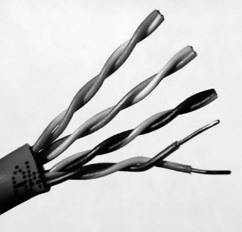
Category 5e (Enhanced) Four twisted wire pairs (eight wires), rated for 100MHz but capable of handling the disturbance on each pair that's caused by transmitting on all four pairs at the same time—a feature that's needed for Gigabit Ethernet. Any category below 5e shouldn't be used in today's network environments.
Figure 3.3 shows a basic Cat 5e cable with the four wire pairs twisted to reduce crosstalk.
Category 6 Four twisted wire pairs (eight wires), rated for 250MHz. Cat 6 became a standard back in June 2002. You would usually use it as riser cable to connect floors together. If you're installing a new network in a new building, there's no reason to use anything but Category 6 UTP cabling as well as running fiber runs between floors.
Category 6a (Augmented) Basic Category 6 cable has a reduced maximum length when used for 10GBaseT; however, Category 6a cable, or Augmented Category 6, is characterized to 500MHz and has improved crosstalk characteristics, which allows 10GBaseT to be run for up to 100 meters. The most important point is a performance difference between Electronic Industries Alliance and Telecommunication Industry Association (EIA/TIA) component specifications for the NEXT (near-end crosstalk) transmission parameter. Running at a frequency of 500MHz, an ISO/IEC Cat 6a connector provides double the power (3db) of a Cat 6A connector that conforms with the EIA/TIA specification. Note that 3dB equals a 100 percent increase of a near-end crosstalk noise reduction. This is our future cable indeed!
Connecting UTP
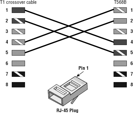
BNC connectors won't fit very well on UTP cable, so you need to use a registered jack (RJ) connector, which you're familiar with because most telephones connect with them. The connector used with UTP cable is called RJ-11 for phones that use four wires; RJ-45 has four pairs (eight wires), as shown in Figure 3.4.

Figure 3.5 shows the pin-outs used in a typical RJ-45 connector. Looking from the bottom of the connector, pin 1 would be on the left.
Most of the time, UTP uses RJ connectors, and you use a crimper to attach them to a cable, just as you would with BNC connectors. The only difference is that the die that holds the connector is a different shape. Higher-quality crimping tools have interchangeable dies for both types of cables. We don't use RJ-11 for local area networks (LANs), but we do use them for our home Digital Subscriber Line (DSL) connections.
RJ-11 uses two wire pairs, and RJ-45 uses four wire pairs.
There's one other type of copper connector called the RJ-48c, which looks exactly like an RJ-45 connector. This plug is very similar to the RJ-45 in that it has four wire pairs, but they are wired differently and used for different circumstances.
RJ-45 is mainly used in LANs with short distances (typically up to 100 meters), where the RJ-48c wiring type would be used with a T1 connection, which is a long-distance wide area network (WAN). In addition, to protect the signal in an RJ-48c, the wires are typically shielded, whereas the RJ-45 uses unshielded wiring.
![]()
Category 5e Cabling Tips
If you want data rates faster than 10Mbps over UTP, ensure that all components are rated to deliver this and be really careful when handling all components. If you yank on Cat 5e cable, it will stretch the number of twists inside the jacket, rendering the Cat 5e label on the outside of the cable invalid. Also, be certain to connect and test all four pairs of wire. Although today's wiring usually uses only two pairs (four wires), the standard for Gigabit Ethernet over UTP requires that all four pairs (eight wires) be in good condition.
Also be aware that a true Cat 5e cabling system uses rated components from end to end, patch cables from workstation to wall panel, cable from wall panel to patch panel, and patch cables from patch panel to hub. So if any components are missing, or if the lengths don't match the Category 5e specification, you just don't have a Category 5e cabling installation. And certify that the entire installation is Category 5e compliant. I've got to warn you that doing this requires some pretty pricey test equipment to make the appropriate measurements!
Fiber-Optic Cable
Because fiber-optic cable transmits digital signals using light impulses rather than electricity, it's immune to EMI and RFI. Anyone who's seen a network's UTP cable run down an elevator shaft would definitely appreciate this fiber feature. Fiber cable allows light impulses to be carried on either a glass or a plastic core. Glass can carry the signal a greater distance, but plastic costs less. Whichever the type of core, it's surrounded by a glass or plastic cladding with a different refraction index that reflects the light back into the core. Around this is a layer of flexible plastic buffer that can be wrapped in an armor coating that's usually Kevlar, which is then sheathed in PVC or plenum.
The cable itself comes in either single-mode fiber (SMF) or multimode fiber (MMF); the difference between them is in the number of light rays (the number of signals) they can carry. Multimode fiber is most often used for shorter-distance applications and single-mode fiber for spanning longer distances.
Although fiber-optic cable may sound like the solution to many problems, it has its pros and cons just like the other cable types.
- It's completely immune to EMI and RFI.
- It can transmit up to 40 kilometers (about 25 miles).
And here are the cons:
- It's difficult to install.
- It's more expensive than twisted-pair.
- Troubleshooting equipment is more expensive than twisted-pair test equipment.
- It's harder to troubleshoot.
Single-Mode Fiber
Single-mode fiber-optic cable (SMF) is a very high-speed, long-distance media that consists of a single strand—sometimes two strands—of glass fiber that carries the signals. Light-emitting diodes (LEDs) and laser are the light sources used with SMF. The light source is transmitted from end to end and pulsed to create communication. This is the type of fiber cable employed to span really long distances because it can transmit data 50 times further than multimode fiber at a faster rate.
Clearly, because the transmission media is glass, the installation of SMF can be a bit tricky. Yes, there are outer layers protecting the glass core, but the cable still shouldn't be crimped or pinched around any tight corners.
Multimode Fiber
Multimode fiber-optic cable (MMF) also uses light to communicate a signal, but with it, the light is dispersed on numerous paths as it travels through the core and is reflected back. A special material called cladding is used to line the core and focus the light back onto it. MMF provides high bandwidth at high speeds over medium distances (up to about 3,000 feet), but beyond that it can be really inconsistent. This is why MMF is most often used within a smaller area of one building; SMF can be used between buildings.
MMF is available in glass or in a plastic version that makes installation a lot easier and increases the installation's flexibility.
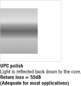
APC vs UPC
The choice between angle-polished connectors (APCs) and ultra-polished connectors (UPCs) can make a pretty big difference on how your network will perform.
The ultra-polished connector looks like what you'd expect to find in a fiber-optic end. The cut is perfectly straight, as shown in Figure 3.6.
The angle-polished connector looks like Figure 3.7. Notice the perfectly cut angle, which seems odd, but there is a reason for this and it's a good one!
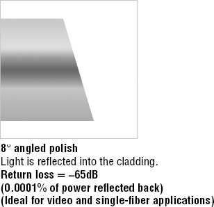
Unlike the UPC, where the light is reflected back down to the core of the fiber cable, which causes a loss of db called a return loss because the angled connector causes the light to reflect back into the cladding—the thick sides of the glass instead of the core. But the APC doesn't cause nearly as much db loss when using this type of connector. Very cool design indeed!
Fiber-Optic Connectors
A whole bunch of different types of connectors are available to use with fiber-optic cables, but the two most popular are the straight tip (ST) and subscriber (or square) connector (SC). The ST fiber-optic connector (developed by AT&T) is one of the most widely used fiber-optic connectors; it uses a BNC attachment mechanism similar to thinnet's that makes connections and disconnections fairly frustration free. In fact, this is the feature that makes this connector so popular. Figure 3.8 shows an example of an ST connector. Notice the BNC attachment mechanism.

The SC connector is another type of fiber-optic connector. As you can see in Figure 3.9, SC connectors are latched—a mechanism holds the connector in securely and prevents it from falling out.

SC connectors work with both single-mode and multimode optical fibers and will last for around 1,000 matings. They're being used more now but still aren't nearly as popular as ST connectors for LAN connections.
Another type of connector I want to mention before moving on to the SFF connector is the FC connector, or field assembly connector, also called the ferrule connector, which isn't very popular. It's still used in telecommunications and measurement equipment with single-mode lasers, but the SC is a way more popular fiber end. The only reason I mention it here is because it is an exam objective; other than that you probably won't ever see it in production. These look identical to ST connectors.
You can also get a fiber coupler in order to connect an ST to an SC connector, for example, but you will lose a lot of your power (db) if you do so.
Small Form Factor Fiber-Optic Connectors
Another cool fiber-optic connector is the small form factor (SFF) connector, which allows more fiber-optic terminations in the same amount of space than its standard-sized counterparts. The two most popular versions are the mechanical transfer registered jack (MT-RJ or MTRJ), designed by AMP, and the Local Connector (LC), designed by Lucent.
![]()
Should I Use Copper or Fiber?
If your data runs are measured in miles, fiber optic is your cable of choice because copper just can't give you more than about 1,500 feet without electronics regenerating the signal. The standards limit UTP to a pathetic 328 feet.
Another good reason to opt for fiber is if you require high security because it doesn't create a readable magnetic field. Although fiber-optic technology was initially super expensive and nasty to work with, it's now commonly used for Gigabit or 10GB Internet backbones.
Ethernet running at 10Mbps over fiber-optic cable to the desktop is designated 10BaseFL; the 100Mbps version of this implementation is 100BaseFX. The L in the 10Mbps version stands for link. Other designations are B for backbone and P for passive.
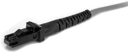
The MT-RJ fiber-optic connector was the first small form factor fiber-optic connector to be widely used, and it's only one-third the size of the SC and ST connectors it most often replaces. It offers these benefits:
- Small size
- TX and RX strands in one connector
- Keyed for single polarity
- Pre-terminated ends that require no polishing or epoxy
- Easy to use
Figure 3.10 shows an example of an MT-RJ fiber-optic connector.
LC is a newer style of SFF fiber-optic connector that's pulling ahead of the MT-RJ. It's especially popular for use with Fibre-Channel adapters (FCs) and is a standard used for fast storage area networks and Gigabit Ethernet adapters. Figure 3.11 depicts an example of the LC connector.
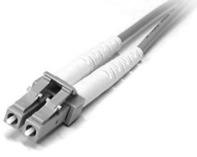
It has similar advantages to MT-RJ and other SFF-type connectors but it's easier to terminate. It uses a ceramic insert just as standard-sized fiber-optic connectors do.
Media Converters
Sometimes, you'll need to convert from one media type to another. Maybe you need to go from one mode of fiber to another mode, or in an even more extreme case, you need to go from fiber to Ethernet. If you're faced with situations like these, you'll need to be familiar with some of the more common media converters:
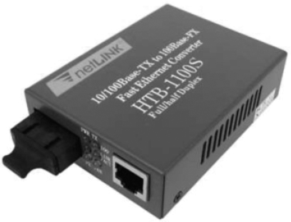
Single-Mode Fiber to Ethernet These devices accept a fiber connector and an Ethernet connector and convert the signal from Ethernet and single-mode fiber (see Figure 3.12).
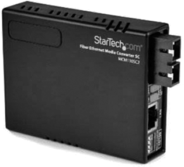
Multimode Fiber to Ethernet These devices accept a fiber connector and an Ethernet connector and convert the signal from Ethernet and multi-mode fiber (see Figure 3.13).
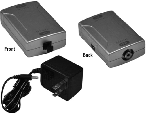
Fiber to Coaxial These devices accept a fiber connector and a coaxial connector and convert digital signals from optical to coax (see Figure 3.14).
Single-Mode to Multimode Fiber These devices accept a single-mode fiber connector and a multimode fiber connector and convert the signals between the two (see Figure 3.15).

Serial Cables
Except for multimode fiber, all the cable varieties I've talked about so far are considered serial cable types. In network communications, serial means that one bit after another is sent out onto the wire or fiber and interpreted by a network card or other type of interface on the other end.
Each 1 or 0 is read separately and then combined with others to form data. This is very different from parallel communication where bits are sent in groups and have to be read together to make sense of the message they represent. A good example of a parallel cable is an old printer cable—which has been replaced by USB, as I'll get to in a minute.
RS-232
Recommended Standard 232 (RS-232) was a cable standard commonly used for serial data signals connecting the DTE and the DCE, such as a computer's serial port to an external modem.
Figure 3.16 shows an example of one of the many types of RS-232 cables. These cables normally connect to a connector on the device called a DB-9.
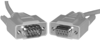
Because laptops don't even come with these types of connectors anymore, they've pretty much been replaced by things like USB, Thunderbolt, and FireWire.
DB-25
Now here's a connector that has been around for a while! The D series of connectors was invented by ITT Cannon in 1952, and the D was followed by A, B, C, D, or E, which described the shell size, then the numbers of pins or sockets. DB-25 tells us we have 25 pins in a “B” size shell. RS-232 devices usually used the DB-25 connector, but today we don't use RS-232 or DB-25, and we rarely use a DB-9, which used to be used for Cisco console cables, but has mostly been replaced by USB.
Universal Serial Bus
Universal Serial Bus (USB) is now the built-in serial bus du jour of most motherboards. You usually get a maximum of 4 external USB interfaces, but add-on adapters can take that up to as many as 16 serial interfaces. USB can actually connect a maximum of 127 external devices, and it's a much more flexible peripheral bus than either serial or parallel.
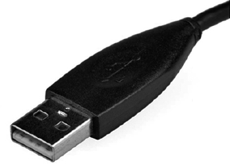
We use USB to connect printers, scanners, and a host of other input devices like keyboards, joysticks, and mice. When connecting USB peripherals, you've got to connect them either directly to one of the USB ports on the PC or to a USB hub that is connected to one of those USB ports. You can get a picture of this in Figure 3.17.

Hubs can be chained together to provide multiple USB connections, but even though you can connect up to 127 devices, it's really not practical to go there. Each device has a USB plug, as shown in Figure 3.18.
Cable Properties
The reason we use so many different types of cables in a network is that each type has its own set of properties that specifically make it the best to use for a particular area or purpose. Different types vary in transmission speeds, distance, duplex, noise immunity, and frequency, and I'll cover each of these next.
Transmission Speeds
Based on the type of cable or fiber you choose and the network that it's installed in, network administrators can control the speed of a network to meet the network's traffic demands. Admins usually permit, or would like to have, transmission speeds of up to 10Gbps or higher on the core areas of their networks that connect various network segments. In the distribution and access areas, where users connect to switches, it's typically 100Mbps per connection, but transmission speeds are creeping up because the traffic demand is getting higher.
Distance
Deciding factors used in choosing what cable type to use often come down to the topology of a network and the distance between its components. Some network technologies can run much further than others without communication errors, but all network communication technologies are prone to attenuation—the degradation of a signal due to the medium itself and the distance signals have to travel. Some cable types suffer from attenuation more than others. For instance, any network using twisted-pair cable should have a maximum segment length of only 328 feet (100 meters).
Duplex
All communications are either half duplex or full duplex. The difference is whether the communicating devices can “talk” and “listen” at the same time.
During half-duplex communication, a device can either send communication or receive communication, but not both at the same time. Think walkie-talkie—when you press the button on the walkie-talkie, you turn the speaker off and you can't hear anything the other side is saying.
In full-duplex communication, both devices can send and receive communication at the same time. This means that the effective throughput is doubled and communication is much more efficient. Full duplex is typical in most of today's switched networks. I'll discuss both full and half duplex in more detail in Chapter 4, “The Current Ethernet Specifications.”
Noise Immunity (Security, EMI)
Any time electrons are pushed through two wires next to each other a magnetic current is created. And we can create a current in the wires. This is good because without magnetic flux we wouldn't be using computers—the power that surges through them is a result of it. The bad news is that it also creates two communications issues.
First, because the wire is creating a current based on the 1s and 0s coursing through it, with the right tools in hand, people can read the message in the wire without cutting it or even removing the insulation. You've heard of this—it's called tapping the wire, and it's clearly a valid security concern. In ancient history, high-security installations like the Pentagon actually encased communication wires in lead shielding to prevent them from being tapped. STP wires make tapping a little harder, but not hard enough.
The best way to solve the magnetic-flux problem caused by electricity is to not use these wires at all. As I said, fiber-optic cables carry the signal as light on a glass or a really pure plastic strand, and light is not susceptible to magnetic flux, making fiber optics a whole lot harder to tap. It's still not impossible—you can do it at the equipment level, but you have to actually cut and then repair the cable to do that, which isn't likely to go unnoticed.
The second magnetic-flux issue comes from the outside in instead of from the inside out. Because wires can take on additional current if they're near any source of magnetism, you've got to be really careful where you run your cables. You can avoid EMI by keeping copper cables away from all powerful magnetic sources like electric motors, speakers, amplifiers, fluorescent light ballasts, and so on. Just keep them away from anything that can generate a magnetic field!
Frequency
Each cable type has a specified maximum frequency that gives you the transmission bandwidth it can handle. Cat 5e cable is tested to 100MHz maximum frequency and can run 1Gbps signals for relatively short distances. That's maxing it out, but it's still good for connecting desktop hosts at high speeds. On the other hand, Cat 6 is a 250MHz cable that can handle 1Gbps data flow all day long with ease. Cat 6 has a lot more twists and thicker cables, so it's best used when connecting floors of a building.
Although a signal is measured as bandwidth, the capacity to carry the signal in a cable is measured as frequency.
Wiring Standards
Ethernet cabling is an important thing to understand, especially if you're planning to work on any type of LAN. There are different types of wiring standards available:
We will look into each one of these, and then I'll end this discussion with some examples for you.
568A vs 568B
If you look inside a network cable, you'll find four pairs of wires twisted together to prevent crosstalk; they're also twisted like this to help prevent EMI and tapping. The same pins have to be used on the same colors throughout a network to receive and transmit, but how do you decide which color wire goes with which pin? The good news is that you don't have to decide—at least not completely.
Two wiring standards have surfaced that have been agreed on by over 60 vendors, including AT&T, 3Com, and Cisco, although there isn't 100 percent agreement. In other words, over the years, some network jacks have been pinned with the 568A standard and some have used the 568B standard, which can cause a bit of confusion if you don't know what you're looking at in your network.
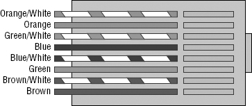
568A By looking at Figure 3.19, you can see that the green pair is used for pins 1 and 2 but the orange pair is split to pins 3 and 6, separated by the blue pair.

568B Now take a look at Figure 3.20. The orange pair is pins 1 and 2 and the green pair is pins 3 and 6, again separated by the blue pair.
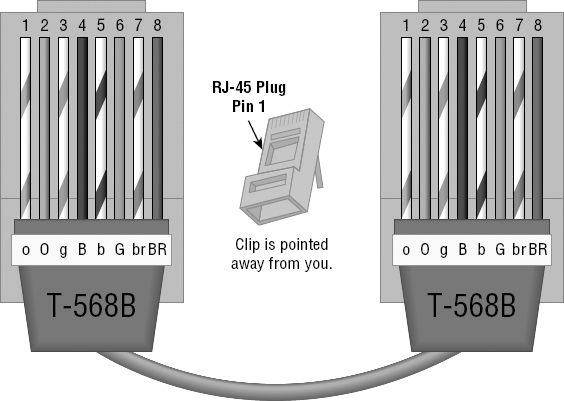
Note that the only difference between T568A and T568B is that pairs 2 and 3 (orange and green) are swapped. Also, you can use a UTP coupler in order to connect two RJ-45 connectors together to lengthen a cable or in order to make a straight-through cable into a crossover, and vice versa.
If you're thinking, “What's the difference, and why does it matter?” the answer is the position of four wires on one side of the cable—that's it! There are eight wires in each UTP cable; pins 4, 5, 7, and 8 aren't used in either standard.
If you're installing new cabling to each cubicle and/or office, you need to make sure to connect all eight pins—and use Cat 5e or Cat 6. Voice over IP (VoIP) uses all eight pins, and it's really common to have voice and data on the same wire at the same time in today's networks.
This only leaves the wire pairs to connect to pins 1, 2, 3, and 6 for data. Remember, if we connect the green-white, green, orange-white, and orange wires to pins 1, 2, 3, and 6, respectively, on both sides of the cable, we're using the 568A standard and creating the kind of straight-through cable that's regularly implemented as a regular patch cable for most networks. On the other hand, if we switch from pin 1 to pin 3 and from pin 2 to pin 6 on one side only, we've created a crossover cable for most networks. Let's take a look.
Straight-Through Cable
The straight-through cable is used to connect a host to a switch or hub or a router to a switch or hub.
No worries—I'll tell you all about devices like switches, hubs, and routers in detail in Chapter 5, “Networking Devices.”
Four wires are used in straight-through cable to connect 10/100 Ethernet devices. It's really pretty simple to do this; Figure 3.21 depicts the four wires used in a straight-through Ethernet cable.

Notice that only pins 1, 2, 3, and 6 are used. Connect 1 to 1, 2 to 2, 3 to 3, and 6 to 6 and you'll be up and networking in no time. Just remember that this would be a 10/100 Ethernet-only cable, so it wouldn't work with 1000Mbps Ethernet, voice, Token Ring, ISDN, and so on.
Crossover Cable
The same four wires are used in this cable, and just as with the straight-through cable, you simply connect the different pins together. Crossover cables can be used to connect these devices:
- Switch to switch
- Hub to hub
- Host to host
- Hub to switch
- Router direct to host
Take a look at Figure 3.22, which demonstrates how each of the four wires are used in a crossover Ethernet cable.
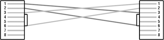
Okay—did you notice that instead of connecting 1 to 1, 2 to 2, and so on, we connected pins 1 to 3 and 2 to 6 on each side of the cable? A crossover cable is typically used to connect two switches together, but it can also be used to test communications between two workstations directly, bypassing the switch.
A crossover cable is used only in Ethernet UTP installations. You can connect two workstation NICs or a workstation and a server NIC directly with it.
If you are trying to match the straight-through and crossover cables with the 568A and 568B standard, here is how it would look:
568A+568A = straight-through
568B+568B = straight-through
568A+568B = crossover

You're going to find out a lot more about how important it is to label basically everything. But for now, make sure to label a crossover cable as what it is so that no one tries to use it as a workstation patch cable. If they do that, the workstation won't be able to communicate with the hub and the rest of the network!
It's really cool that you can carry a crossover cable with you in your tool bag along with your laptop—then, if you want to ensure that a server's NIC is functioning correctly, you can just connect your laptop directly to the server's NIC using your handy crossover cable. You should be able to log in to the server if both NICs are configured correctly.
Use a cable tester to make sure that what you're dealing with is in fact a crossover cable. The tester can also tell you if there's a problem with the cable. Figure 3.23 shows an inexpensive cable tester for UTP.
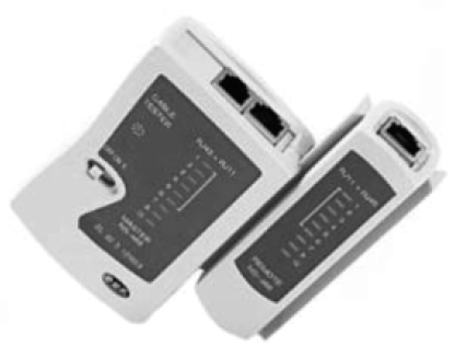
This cost-effective little tool will tell you beyond a shadow of a doubt if you have a straight-through or crossover cable—or even if there's a problem with the cable.
UTP Gigabit Wiring (1000BaseT)
In the previous examples of 10BaseT and 100BaseT UTP wiring, only two wire pairs were used, but that's just not good enough for Gigabit UTP transmission.
1000BaseT UTP wiring (Figure 3.24) requires four wire pairs and uses more advanced electronics so that each and every pair in the cable can transmit simultaneously. Even so, gigabit wiring is almost identical to my earlier 10/100 example, except that we'll use the other two pairs in the cable.
For a straight-through cable it's still 1 to 1, 2 to 2, and so on up to pin 8. And in creating the gigabit crossover cable, you'd still cross 1 to 3 and 2 to 6, but you would add 4 to 7 and 5 to 8—pretty straightforward!
Rolled/Rollover Cable
Although rolled cable isn't used to connect any Ethernet connections together, you can use a rolled Ethernet cable to connect a host EIA-TIA 232 interface to a router console serial communication (COM) port.
If you have a Cisco router or switch, you would use this cable to connect your PC, Mac, or a device like an iPad to the Cisco hardware. Eight wires are used in this cable to connect serial devices, although not all eight are used to send information, just as in Ethernet networking. Figure 2.14 shows the eight wires used in a rolled cable.

These are probably the easiest cables to make because you just cut the end off on one side of a straight-through cable, turn it over, and put it back on—with a new connector, of course!
T1 Crossover Cable
In Chapter 15 you'll be introduced to a device called the CSU/DSU. This device may be your connection to the Internet for the enterprise. The type of cable you use to connect to this device from your router depends on the interface types that are available on the router.
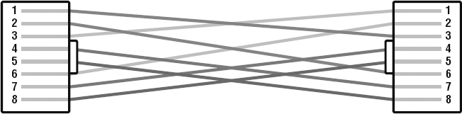
The router may connect with several types of serial cables if a T1 connection is not built into it. If a T1 connection is built into the router, you will use an Ethernet cable. Figure 3.26 shows a T1 crossover cable connected to a T568B connection.
In rare instances you may have the need to run a cable between two CSU/DSUs. In that case you would need a T1 crossover cable. A T1 cable uses T568B pairs 1 and 2, so to connect two T1 CSU/DSU devices back-to-back requires a crossover cable that swaps these pairs. Specifically, pins 1, 2, 4, and 5 are connected to 4, 5, 1, and 2, respectively.
Test Your Cable Understanding
You've taken a look at the various RJ-45 UTP cables. With that in mind, what cable is used between the switches in the following image?

For host A to ping host B, you need a crossover cable to connect the two switches together. But what types of cables are used in the network shown in the following image?
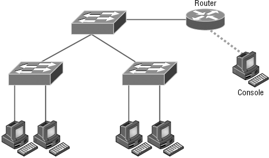
In the second example, there are a variety of cables in use. For the connection between the switches, we'd clearly use a crossover cable like the one you saw in the earlier example. The trouble is, here we have a console connection that uses a rolled cable. Plus, the connection from the router to the switch is a straight-through cable, which is also what's running between the hosts to the switches.
Installing Wiring Distributions
By now, you're probably getting the idea that there are a lot more components in the average computer networks than meets the eye, right? If this isn't exactly a news bulletin to you, then you either already are, or have been, involved in the initial installation of a network. If the latter describes you, you probably will be, or already are, involved in the purchase and installation of the components that will connect the computers throughout your organization's building. And it may also be up to you to verify that all of the network components have been installed properly and tested. So, let's go over each of these components and the process of verifying their proper installation.
MDF/IDF
The main distribution frame (MDF) is a wiring point that's generally used as a reference point for telephone lines. It's also considered the WAN termination point. It's installed in the building as part of the prewiring, and the internal lines are connected to it. After that, all that's left is to connect the external (telephone company) lines to the other side to complete the circuit. Often, another wire frame called an intermediate distribution frame (IDF) is located in an equipment or telecommunications room. It's connected to the MDF and is used to provide greater flexibility for the distribution of all the communications lines to the building. It's typically a sturdy metal rack designed to hold the bulk of cables coming from all over the building!
25 Pair
A 25-pair cable consists of 25 individual pairs of wires all inside one common insulating jacket. It's not generally used for data cabling, just for telephone cabling, and especially for backbone and cross-connect cables because it reduces the cable clutter significantly. This type of cable is often referred to as a feeder cable because it supplies signal to many connected pairs.
66 Block
If you know what a 66 block is, you're either really old or work in an old building since they came out in 1962 and can really only be used for old analog telephone connections. This uses the 25-pair cable I just mentioned and is a standard termination block containing 50 rows, which created an industry standard for easy termination of voice cabling
110 Block
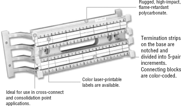
A newer type of wiring distribution point called a 110 block has replaced most telephone wire installations and is also used for computer networking. On one side, wires are punched down; the other side has RJ-11 (for phone) or RJ-45 (for network) connections.
You'll find 110 blocks in sizes from 25 to more than 500 wire pairs, and some are capable of carrying 1Gpbs connections when used with Category 6 cables. The hitch is that using Cat 6 with the 110 block is really difficult because of the size of the Cat 6 wiring. Figure 3.27 shows a 110 block and describes each section used in the 110 block.
Demarc/Demarc Extension
The demarc (short for demarcation) is the last point of responsibility for the service provider. It's often at the MDF in your building connection, especially if your building is large, but it's usually just an RJ-45 jack that your channel service unit/data service unit (CSU/DSU) connects from your router to wide area network (WAN) connections. I'll thoroughly cover CSU/DSUs in Chapter 16, “Wide Area Networks”.
When troubleshooting, network admins often test for connectivity on both sides of the demarc to determine if the problem is internal or external. The length of copper or fiber that begins after the demarc but still doesn't reach all the way up to your office is referred to as a demarc extension.
Smart Jack
A smart jack, also called a network interface device (NID) or network interface unit (NIU), is owned by the PSTN and is a special network interface that's often used between the service provider's network and the internal network. You can't physically test to an actual demarc because it's just an RJ-45 jack, but the service provider may install an NID that has power and can be looped for testing purposes.
The smart-jack device may also provide for code and protocol conversion, making the signal from the service provider usable by the devices on the internal network like the CSU/DSU.
![]()
Above and Beyond the Network+!
If you have a Cisco router that is having a problem—such as a serial WAN connection issue—and you're using a serial port on your router to connect to a port on a CSU/DSU, type this at the enabled Cisco router console or Telnet port:
config t
int s0/0
loopback
At this point, your interface will come up and look like it is working. That is, of course, if your connection from the router to the CSU/DSU is working properly. If not, you have a local problem.
Summary
I know getting through this chapter probably wasn't the most fun you've had recently. But understanding all those types of wires and cabling, along with their unique capacities, their associated standards, and the right connectors to use with them plus where to place them, is integral to having a solid, foundational understanding of the things that make a great network run quickly and reliably.
It's critical for you to grasp the basics of networking. Having the facts about how a good network is designed and implemented and what goes into that process will make you an effective and efficient technician—and maybe, some day, a highly paid system administrator.
Exam Essentials
Understand the various types of cables used in today's networks. Coaxial (other than for cable modems) is rarely used, but twisted-pair and fiber-optic cable are very common in today's networks.
Understand the various types of ends that are used on each type of cable. Coax uses BNC; twisted-pair uses RJ-11 for voice and RJ-45 for data; and fiber uses various ends, depending on its use.
Describe the various types of media converters that are available. These include single-mode fiber to Ethernet, multimode fiber to Ethernet, fiber to coaxial, and single-mode to multimode fiber.
Understand what a 568A to 568A cable is. A 568A to 568A cable is also known as an Ethernet straight-through cable and is used to connect hosts to switches, for example.
Understand what a 568A to 568B cable is. A 568A to 568B cable is also known as an Ethernet crossover cable and is used to connect switches to switches, for example.
Define the function of a T1 crossover cable. In rare instances, you may have the need to run a cable between two CSU/DSUs. In that case, you will need a T1 crossover cable. A T1 cable uses T568B pairs 1 and 2, so to connect two T1 CSU/DSU devices back-to-back requires a crossover cable that swaps these pairs. Specifically, pins 1, 2, 4, and 5 are connected to 4, 5, 1, and 2, respectively.
Written Lab
You can find the answers in Appendix A.
- Which UTP wiring uses four twisted wire pairs (eight wires) and is rated for 250MHz?
- The point at which the operational control or ownership changes from your company to a service provider is referred to as __________.
- Which type of cable will you use to connect two switches to each other?
- Which RG rating of coax is used for cable modems?
- Which UTP uses four twisted wire pairs (eight wires), is rated for 100MHz, and is capable of handling the disturbance on each pair caused by transmitting on all four pairs at the same time?
- You want to connect a host to a switch port. What type of Ethernet cable will you use?
- In what instance would you use T1 crossover cable?
- 568A uses which pins to make a connection?
- A crossover uses which pins to make a connection?
- What are two advantages of fiber-optic cabling?
Review Questions
You can find the answers to the review questions in Appendix B.
- Why would a network administrator use plenum-rated cable during an installation? (Choose two.)
- Low combustion temperature
- High combustion temperature
- Reduces toxic gas released during a fire
- Is not susceptible to any interference
- Which of the following Ethernet unshielded twisted-pair cabling types are commonly used?
- 10BaseT
- 100BaseTX
- 1000BaseTX
- All of the above
- In which of the following categories is UTP cable not rated?
- Category 2
- Category 3
- Category 5e
- Category 8
- What type of connector does UTP cable typically use?
- BNC
- ST
- RJ-45
- SC
- Which of the following provides the longest cable run distance?
- Single-mode fiber
- Multimode fiber
- Category 3 UTP
- Coax
- You need to crimp on a connector using an RJ-45 connector. Which pin-out configuration would you use to connect a host into a switch?
- Fiber-optic cable is immune to electromagnetic interference (EMI) and radio frequency interference (RFI) because it __________.
- Transmits analog signals using electricity
- Transmits analog signals using light impulses
- Transmits digital signals using light impulses
- Transmits digital signals using electricity
- What type of cable transmits lights from end to end?
- Coax
- Fiber-optic
- UTP
- Category 2
- What is the main difference between single-mode fiber (SMF) and multimode fiber (MMF)?
- Electrical signals
- Number of light rays
- Number of digital signals
- Signal-mode can be run a shorter distance
- What type of cable should be used if you need to make a cable run longer than 100 meters?
- Category 5e
- Category 6
- Fiber-optic
- Coaxial
- Which of the following are fiber-optic connectors? (Select three.)
- BNC
- ST
- RJ-11
- SC
- LC
- RJ-45
- You need to connect two devices on a network and they need to send voice traffic. Which of the following cable will you use?
- How many hosts on a half-duplex segment can talk at one time?
- 0
- 1
- 2
- Unlimited
- On which type of cable does EMI have the least effect?
- Coax
- Fiber-optic
- UTP
- STP
- How many devices can be connected to a full-duplex segment?
- 0
- 1
- 2
- 4
- How many wires are used in a 100Mbps UTP transmission?
- 2
- 4
- 6
- 8
- A crossover cable is used to connect all of the following except __________.
- Switch to switch
- Host to host
- Hub to switch
- Host to switch
- How is a T1 crossover cable wired?
- Pins 1, 2, 4, and 5 are connected to 4, 5, 1, and 2.
- Pins 2, 3, 4, and 5 are connected to 4, 5, 1, and 2.
- Pins 1, 2, 4, and 5 are connected to 3, 4, 5, and 6.
- Pins 4, 5, 6, and 7 are connected to 4, 5, 1, and 2.
- The purpose of the demarcation point is to separate the customer from whom?
- You need to make a 568B cable for a Fast Ethernet link. How many pairs will you use?
- 1
- 2
- 3
- 4