
Chapter 4
The Current Ethernet Specifications
THE FOLLOWING COMPTIA NETWORK+ EXAM OBJECTIVES ARE COVERED IN THIS CHAPTER:
- 1.0 Network architecture
- 1.8 Given a scenario, implement and configure the appropriate addressing schema
- MAC addressing
- 5.0 Industry standards, practices, and network theory
- 5.2 Explain the basics of network theory and concepts
- Numbering systems
- Binary
- Hexadecimal
- Octal
- Broadband/baseband
- Bit rates vs baud rate
- Sampling size
- CSMA/CD and CSMA/CA
- Carrier detect/sense
- Wavelength
- Collision
- Numbering systems
- 5.4 Given a scenario, deploy the appropriate wired connectivity standard
- Ethernet standards
- 10BaseT
- 100BaseT
- 1000BaseT
- 1000BaseTX
- 10GBaseT
- 100BaseFX
- 10Base2
- 10GBaseSR
- 10GBaseER
- 10GBaseSW
- IEEE 1901-2013
- Ethernet over HDMI
- Ethernet over power line
- Ethernet standards

Before we dive into the complex worlds of networking devices, the TCP/IP and DoD models, IP addressing, subnetting, and routing in the upcoming chapters, you have to understand the big picture of LANs and learn the answer to these key questions: How is Ethernet used in today's networks? What are Media Access Control (MAC) addresses, and how are these identifiers utilized in networking?
This chapter will answer those questions and more. I'll not only discuss the basics of Ethernet and the way MAC addresses are used on an Ethernet LAN, I'll also cover the protocols used with Ethernet at the Data Link layer. You'll also learn about the various Ethernet specifications.
So now, let's get started with the fundamentals of connecting two hosts together.

To find up-to-the-minute updates for this chapter, please see www.lammle.com/networkplus or the book's website at www.sybextestbanks.wiley.com.
Network Basics
Networks and networking have grown exponentially over the last 20 years—understandably so. They've had to evolve at light speed just to keep up with huge increases in basic mission-critical user needs ranging from sharing data and printers to more advanced demands like videoconferencing. Unless everyone who needs to share network resources is located in the same office area (an increasingly uncommon situation), the challenge is to connect the sometimes large number of relevant networks together so all users can share the networks’ wealth.
Let's take a look at how communication happens on a basic local area network (LAN), which I started to discuss in Chapter 1, “Introduction to Networks.” Starting with Figure 4.1, you get a picture of a basic LAN network that's connected together using an Ethernet connection to a hub. This network is actually one collision domain and one broadcast domain, but don't stress if you have no idea what this means—I'm going to talk about both collision and broadcast domains in depth in Chapter 5, “Networking Devices.”

Okay, about Figure 4.1; how would you say the PC named Bob communicates with the PC named Sally? Well, they're both on the same LAN connected with a multiport repeater (a hub). So does Bob just send out a data message, “Hey Sally, you there?” or does Bob use Sally's IP address and put things more like, “Hey 192.168.0.3, are you there?” I hope you picked the IP address option, but even if you did, the news is still bad—both answers are wrong! Why? Because Bob is actually going to use Sally's MAC address (known as a hardware address), which is burned right into the network card of Sally's PC, to get a hold of her.
This is all good, but how does Bob get Sally's MAC address when Bob knows only Sally's name and doesn't even have her IP address? Bob is going to start by using name resolution (hostname-to-IP-address resolution), something that's usually accomplished using Domain Name Service (DNS). And note that if these two hosts are on the same LAN, Bob can just broadcast to Sally asking her for the information (no DNS needed)—welcome to Microsoft Windows!
Here's the output from a network analyzer depicting a simple name-resolution process from Bob to Sally:
Time       Source       Destination    Protocol   Info
53.892794  192.168.0.2  192.168.0.255  NBNS       Name query NB SALLY<00>
As I already mentioned, because the two hosts are on a local LAN, Windows (Bob) will broadcast to resolve the name Sally (the destination 192.168.0.255 is a broadcast address). Let's take a look at the rest of the information:
EthernetII,Src:192.168.0.2(00:14:22:be:18:3b),Dst:Broadcast(ff:ff:ff:ff:ff:ff)
This output shows that Bob knows his own MAC address and source IP address, but not Sally's IP address or MAC address. So, Bob sends a broadcast address of all Fs for the MAC address (a Data Link layer broadcast) and an IP LAN broadcast of 192.168.0.255. Again, no worries—you're going to learn all about broadcasts in Chapter 6, “Introduction to the Internet Protocol.”
Before the name is resolved, the first thing Bob has to do is broadcast on the LAN to get Sally's MAC address so he can communicate to her PC and resolve her name to an IP address:
Time       Source       Destination Protocol Info
5.153054   192.168.0.2  Broadcast   ARP Who has 192.168.0.3? Tell 192.168.0.2
Next, check out Sally's response:
Time         Source       Destination  Protocol  Info
5.153403     192.168.0.3  192.168.0.2  ARP  192.168.0.3 is at 00:0b:db:99:d3:5e
5.53.89317   192.168.0.3  192.168.0.2  NBNS Name query response NB 192.168.0.3
Okay, sweet—Bob now has both Sally's IP address and her MAC address (00:0b:db:99:de:5e). These are both listed as the source address at this point because this information was sent from Sally back to Bob. So, finally, Bob has all the goods he needs to communicate with Sally. And just so you know, I'm also going to tell you all about Address Resolution Protocol (ARP) and show you exactly how Sally's IP address was resolved to a MAC address a little later, in Chapter 6.
Importantly, I want you to understand that Sally still had to go through the same resolution processes to communicate back to Bob—sounds crazy, huh? Consider this welcome to IPv4 and basic networking with Windows—and we haven't even added a router yet!
Ethernet Basics
Ethernet is a contention media-access method that allows all hosts on a network to share the same bandwidth of a link. Ethernet is popular because it's readily scalable, meaning that it's comparatively easy to integrate new technologies, such as Fast Ethernet and Gigabit Ethernet, into an existing network infrastructure. It's also relatively simple to implement in the first place, and with it, troubleshooting is reasonably straightforward.
Ethernet uses both Data Link and Physical layer specifications, and this part of the chapter will give you both the Data Link layer and Physical layer information you need to effectively implement, troubleshoot, and maintain an Ethernet network.
In the following sections, I'll also cover some basic terms used in networking with Ethernet technologies. Let's start with collision domains.
Collision Domain
The term collision domain is an Ethernet term that refers to a particular network scenario wherein one device sends a packet out on a network segment and thereby forces every other device on that same physical network segment to pay attention to it. This is bad because if two devices on one physical segment transmit at the same time, a collision event—a situation where each device's digital signals interfere with another on the wire—occurs and forces the devices to retransmit later. Collisions have a dramatically negative effect on network performance, so they're definitely something we want to avoid!
The situation I just described is typically found in a hub environment where each host segment connects to a hub that represents only one collision domain and one broadcast domain. This begs the question, What's a broadcast domain?
Broadcast Domain
Here's that answer: A broadcast domain refers to the set of all devices on a network segment that hear all the broadcasts sent on that segment.
Even though a broadcast domain is typically a boundary delimited by physical media like switches and repeaters, it can also reference a logical division of a network segment where all hosts can reach each other via a Data Link layer (hardware address) broadcast.
That's the basic story, but rest assured, I'll be delving deeper into the skinny on collision and broadcast domains a bit later, in Chapter 5.
CSMA/CD
Ethernet networking uses Carrier Sense Multiple Access with Collision Detection (CSMA/CD), a media access control method that helps devices share the bandwidth evenly without having two devices transmit at the same time on the network medium. CSMA/CD was created to overcome the problem of those collisions that occur when packets are transmitted simultaneously from different hosts. And trust me—good collision management is crucial because when a host transmits in a CSMA/CD network, all the other hosts on the network receive and examine that transmission. Only bridges, switches, and routers, but not hubs, can effectively prevent a transmission from propagating throughout the entire network.
So, how does the CSMA/CD protocol work? Let's start by taking a look at Figure 4.2, where a collision has occurred in the network.
When a host wants to transmit over the network, it first checks for the presence of a digital signal on the wire. If all is clear, meaning that no other host is transmitting, the host will then proceed with its transmission. But it doesn't stop there. The transmitting host constantly monitors the wire to make sure no other hosts begin transmitting. If the host detects another signal on the wire, it sends out an extended jam signal that causes all hosts on the segment to stop sending data (think busy signal). The hosts respond to that jam signal by waiting a while before attempting to transmit again. Backoff algorithms, represented by the clocks counting down on either side of the jammed devices, determine when the colliding stations can retransmit. If collisions keep occurring after 15 tries, the hosts attempting to transmit will then time out. Pretty clean!

When a collision occurs on an Ethernet LAN, the following things happen:
- A jam signal informs all devices that a collision occurred.
- The collision invokes a random backoff algorithm.
- Each device on the Ethernet segment stops transmitting for a short time until the timers expire.
- All hosts have equal priority to transmit after the timers have expired.
And following are the effects of having a CSMA/CD network that has sustained heavy collisions:
- Delay
- Low throughput
- Congestion
Backoff on an 802.3 network is the retransmission delay that's enforced when a collision occurs. When a collision occurs, a host will resume transmission after the forced time delay has expired. After this backoff delay period has expired, all stations have equal priority to transmit data.
Broadband/Baseband
We have two ways to send analog and digital signals down a wire: broadband and baseband.
We hear the term broadband a lot these days because that is pretty much what everyone uses at home. It allows us to have both our analog voice and digital data carried on the same network cable or physical medium. Broadband allows us to send multiple frequencies of different signals down the same wire at the same time (called frequency-division multiplexing), and to send both analog and digital signals.
Baseband is what all LANs use. This is where all the bandwidth of the physical media is used by only one signal. For example, Ethernet uses only one digital signal at a time, and requires all the available bandwidth. If multiple signals are sent from different hosts at the same time, we get collisions; same with wireless, except that uses only analog signaling.
Bit Rates vs Baud Rate
Bit rate is a measure of the number of data bits (0s and 1s) transmitted in one second in either a digital or analog signal. A figure of 56,000 bits per second (bps) means 56,000 0s or 1s can be transmitted in one second, which we simply refer to as bps.
In the 1970s and 1980s, we used the term baud rate a lot, but that was replaced by bps because it was more accurate. Baud was a term of measurement named after a French engineer, Jean-Maurice-Emile Baudot, because he used it to measure the speed of telegraph transmissions.
One baud is one electronic state change per second—for example, from 0.2 volts to 3 volts or from binary 0 to 1. However, since a single state change can involve more than a single bit of data, the bps unit of measurement has replaced it as a more accurate definition of how much data you're transmitting or receiving.
Wavelength
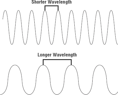
Has anyone every told you that they were on the same wavelength as you? That means they thought you were basically thinking the same way they were. The same is true of the inverse—if they say, “you're not on the same wavelength.” With electromagnetic radiation, radio waves, light waves, or even infrared (heat) waves make characteristic patterns as they travel through space. Some patterns can be the same, and some can be different, as shown in Figure 4.3.
Each wave pattern has a certain shape and length. The distance between peaks (high points) is called wavelength. If two wavelengths are different, we would say they're not on the same wavelength and that is the way we tell different kinds of electromagnetic energy apart. We can use this to our advantage in electronics by sending traffic on different wavelengths at the same time.
In the following sections, I'm going to cover Ethernet in detail at both the Data Link layer (Layer 2) and the Physical layer (Layer 1).
Sampling -Size
At its core, computers work one step at a time by turning a succession of switches on or off at very high speed. In order for a computer to convert analog audio signals to digital signals in a discrete step, the analog waveform is mathematically described as a succession of discrete amplitude values.
When converting to analog, the computer captures a series of samples in specified sizes, which we'll call the sampling size. Each data stream sample contains items like dynamic range, frequency content, and more.
The measured amplitude level in each sample is quantized by being given a value of the nearest measured increment. A computer will reproduce these values and play them back in the same order and at the same rate at which they were captured, producing a copy of the original waveform. This is called the sample rate or sample size. The number of bits transmitted per second is called the bit rate.
Half- and Full-Duplex Ethernet
Just so you know, half-duplex Ethernet is defined in the original 802.3 Ethernet specification. Basically, when you run half duplex, you're using only one wire pair with a digital signal either transmitting or receiving. This really isn't all that different from full duplex because you can both transmit and receive—you just don't get to do that at the same time running half duplex as you can if you're running full duplex.
Here's how it works: If a host hears a digital signal, it uses the CSMA/CD protocol to help prevent collisions and to permit retransmitting if a collision does occur. Half-duplex Ethernet—typically 10BaseT—is only about 30 to 40 percent efficient because a large 10BaseT network will usually provide only 3Mbps to 4Mbps at most. Although it's true that 100Mbps Ethernet can and sometimes does run half duplex, it's just not very common to find that happening anymore.
In contrast, full-duplex Ethernet uses two pairs of wires at the same time instead of one measly wire pair like half duplex employs. Plus, full duplex uses a point-to-point connection between the transmitter of the sending device and the receiver of the receiving device (in most cases the switch). This means that with full-duplex data transfer, you not only get faster data-transfer speeds, but you also get collision prevention too—sweet!
You don't need to worry about collisions because now it's like a freeway with multiple lanes instead of the single-lane road provided by half duplex. Full-duplex Ethernet is supposed to offer 100 percent efficiency in both directions—for example, you can get 20Mbps with a 10Mbps Ethernet running full duplex or 200Mbps for Fast Ethernet. But this rate is something known as an aggregate rate, which translates as “you're supposed to get” 100 percent efficiency. No guarantees, in networking as in life.
Full-duplex Ethernet can be used in many situations; here are some examples:
- With a connection from a switch to a host
- With a connection from a switch to a switch
- With a connection from a host to a host using a crossover cable
You can run full duplex with just about any device except a hub.
You may be wondering: If it's capable of all that speed, why wouldn't it deliver? Well, when a full-duplex Ethernet port is powered on, it first connects to the remote end and then negotiates with the other end of the Fast Ethernet link. This is called an auto-detect mechanism. This mechanism first decides on the exchange capability, which means it checks to see if it can run at 10, 100, or even 1000Mbps. It then checks to see if it can run full duplex, and if it can't, it will run half duplex instead.
Hosts usually auto-detect both the Mbps and the duplex type available (the default setting), but you can manually set both the speed and duplex type on the Network Interface Card (NIC), as shown in the following screen shot.

Today, it's pretty rare to go into a NIC configuration on a host and change these settings, but this example demonstratess that you can do that if you want.
Remember that half-duplex Ethernet shares a collision domain and provides a lower effective throughput than full-duplex Ethernet, which typically has a private collision domain and a higher effective throughput.
Lastly, remember these important points:
- There are no collisions in full-duplex mode.
- A dedicated switch port is required for each full-duplex host.
- The host network card and the switch port must be capable of operating in full-duplex mode.
Now let's take a look at how Ethernet works at the Data Link layer.
Ethernet at the Data Link Layer
Ethernet at the Data Link layer is responsible for Ethernet addressing, commonly referred to as hardware addressing or MAC addressing. Ethernet is also responsible for framing packets received from the Network layer and preparing them for transmission on the local network through the Ethernet contention media-access method known as CSMA/CD.
Ethernet MAC addresses are made up of hexadecimal addresses. So before I discuss MAC addresses, let's start by talking about binary, decimal, and hexadecimal addresses and how to convert one to another.
Binary to Decimal and Hexadecimal Conversion
Understanding the differences between binary, decimal, and hexadecimal numbers and how to convert one format into the other is very important before we move on to discussing the TCP/IP protocol stack and IP addressing in Chapters 6 and 7.
So let's get started with binary numbering. It's pretty simple, really. Each digit used is limited to being either a 1 (one) or a 0 (zero), and each digit is called 1 bit (short for binary digit). Typically, you count either 4 or 8 bits together, with these being referred to as a nibble and a byte, respectively.
What's interesting about binary numbering is the value represented in a decimal format—the typical decimal format being the base-10 number scheme that we've all used since kindergarten. The binary numbers are placed in a value spot, starting at the right and moving left, with each spot having double the value of the previous spot.
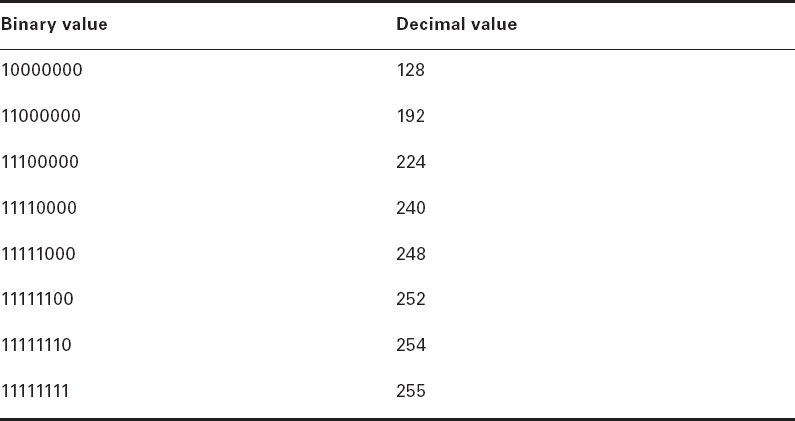
Table 4.1 shows the decimal values of each bit location in a nibble and a byte. Remember, a nibble is four bits and a byte is eight bits. In network addressing, we often refer to a byte as an octet or octal addressing. Mathematically, octal addressing actually refers to base 8, which is completely different from the base 10 we are familiar with. So, technically speaking we are using the term incorrectly, but it's the common usage anyway. When we get to the subnetting chapter, you'll see that I'll use byte and octet interchangeably when discussing IP addressing.

What all this means is that if a one digit (1) is placed in a value spot, then the nibble or byte takes on that decimal value and adds it to any other value spots that have a 1. And if a zero (0) is placed in a bit spot, you don't count that value.
Let me clarify things for you—if we have a 1 placed in each spot of our nibble, we then add up 8 + 4 + 2 + 1 to give us a maximum value of 15. Another example for our nibble values is 1010, which means that the 8 bit and the 2 bit are turned on and equal a decimal value of 10. If we have a nibble binary value of 0110, then our decimal value is 6 because the 4 and 2 bits are turned on.
But the byte values can add up to a value that's significantly higher than 15. This is how—if we count every bit as a one (1), then the byte binary value looks like this (remember, 8 bits equal a byte):
11111111
We then count up every bit spot because each is turned on. It looks like this, which demonstrates the maximum value of a byte:
128 + 64 + 32 + 16 + 8 + 4 + 2 + 1 = 255
A binary number can equal plenty of other decimal values. Let's work through a few examples:
10010110
Which bits are on? The 128, 16, 4, and 2 bits are on, so we'll just add them up: 128 + 16 + 4 + 2 = 150.
01101100
Which bits are on? The 64, 32, 8, and 4 bits are on, so we add them up: 64 + 32 + 8 + 4 = 108.
11101000
Which bits are on? The 128, 64, 32, and 8 bits are on, so we add the values: 128 + 64 + 32 + 8 = 232.
You should memorize Table 4.2 before braving the IP sections in Chapter 6 and Chapter 7 since this lists all available subnet masks.
Hexadecimal addressing is completely different than binary or decimal—it's converted by reading nibbles, not bytes. By using a nibble, we can convert these bits to hex pretty simply. First, understand that the hexadecimal addressing scheme uses only the numbers 0 through 9. And because the numbers 10, 11, 12, and so on can't be used (because they are two-digit numbers), the letters A, B, C, D, E, and F are used to represent 10, 11, 12, 13, 14, and 15, respectively.
Table 4.3 shows both the binary value and the decimal value for each hexadecimal digit.
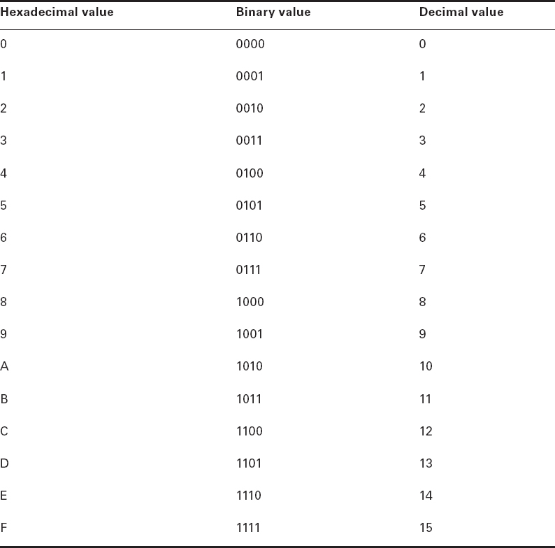
Did you notice that the first 10 hexadecimal digits (0–9) are the same values as the decimal values? If not, look again. This handy fact makes those values super easy to convert.
So suppose you have something like this: 0x6A. (Some manufacturers put 0x in front of characters so you know that they're a hex value, while others just give you an h. It doesn't have any other special meaning.) What are the binary and decimal values? To correctly answer that question, all you have to remember is that each hex character is one nibble and two hex characters together make a byte. To figure out the binary value, first put the hex characters into two nibbles and then put them together into a byte. 6 = 0110 and A (which is 10 in hex) = 1010, so the complete byte is 01101010.
To convert from binary to hex, just take the byte and break it into nibbles.
Here's how you do that: Say you have the binary number 01010101. First, break it into nibbles—0101 and 0101—with the value of each nibble being 5 because the 1 and 4 bits are on. This makes the hex answer 0x55. And in decimal format, the binary number is 01010101, which converts to 64 + 16 + 4 + 1 = 85.
Okay, now try another binary number:
11001100
Our answer is 1100 = 12 and 1100 = 12 (therefore, it's converted to CC in hex). The decimal conversion answer is 128 + 64 + 8 + 4 = 204.
One more example, and then we need to get working on the Physical layer. Suppose we're given the following binary number:
10110101
The hex answer is 0xB5 because 1011 converts to B and 0101 converts to 5 in hex value. The decimal equivalent is 128 + 32 + 16 + 4 + 1 = 181.
See the written lab at the end of this chapter for more practice with binary/hex/decimal conversion.
Ethernet Addressing
Now that you've got binary-to-decimal and hexadecimal address conversion down, we can get into how Ethernet addressing works. It uses the Media Access Control (MAC) address burned into each and every Ethernet NIC. The MAC, or hardware, address is a 48-bit (6-byte) address written in a hexadecimal format.
Figure 4.4 shows the 48-bit MAC addresses and how the bits are divided.
The organizationally unique identifier (OUI) is assigned by the Institute of Electrical and Electronics Engineers (IEEE) to an organization. It's composed of 24 bits, or 3 bytes. The organization, in turn, assigns a globally administered address (24 bits, or 3 bytes) that is unique to each and every adapter it manufactures. Look closely at the figure. The Individual/Group (I/G) address bit is used to signify if the destination MAC address is a unicast or a multicast/broadcast Layer 2 address. If the bit is set to 0, then it is an Individual MAC address and is a unicast address. If the bit is set to 1, it is a Group address and is a multicast/broadcast address.
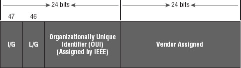
The next bit is the Local/Global bit (L/G). This bit is used to tell if the MAC address is the burned-in-address (BIA) or a MAC address that has been changed locally. You'll see this happen when we get to IPv6 addressing. The low-order 24 bits of an Ethernet address represent a locally administered or manufacturer-assigned code. This portion commonly starts with 24 0s for the first card made and continues in order until there are 24 1s for the last (16,777,216th) card made. You'll find that many manufacturers use these same six hex digits as the last six characters of their serial number on the same card.
Ethernet Frames
The Data Link layer is responsible for combining bits into bytes and bytes into frames. Frames are used at the Data Link layer to encapsulate packets handed down from the Network layer for transmission on a type of physical media access.
The function of Ethernet stations is to pass data frames between each other using a group of bits known as a MAC frame format. This provides error detection from a cyclic redundancy check (CRC). But remember—this is error detection, not error correction. The 802.3 frames and Ethernet frame are shown in Figure 4.5.

Encapsulating a frame within a different type of frame is called tunneling.
The following information regarding frame headings and the various types of Ethernet frames are beyond the scope of the CompTIA Network+ objectives. Throughout the rest of this book, I'll show you screen shots from a network analyzer. It's always good to understand what you are looking at, so I put this information in to help you understand a frame structure.
Following are the details of the different fields in the 802.3 and Ethernet frame types:
Preamble An alternating 1,0 pattern provides a 5MHz clock at the start of each packet, which allows the receiving devices to lock the incoming bit stream.
Start of Frame Delimiter (SOF)/Synch The preamble is seven octets, and the start of a frame (SOF) is one octet (synch). The SOF is 10101011, where the last pair of 1s allows the receiver to come into the alternating 1,0 pattern somewhere in the middle and still synch up and detect the beginning of the data.
Destination Address (DA) This transmits a 48-bit value using the least significant bit (LSB) first. The DA is used by receiving stations to determine whether an incoming packet is addressed to a particular host and can be an individual address or a broadcast or multicast MAC address. Remember that a broadcast is all 1s (or Fs in hex) and is sent to all devices, but a multicast is sent only to a similar subset of hosts on a network.
Source Address (SA) The SA is a 48-bit MAC address used to identify the transmitting device, and it uses the LSB first. Broadcast and multicast address formats are illegal within the SA field.
Length or Type 802.3 uses a Length field, but the Ethernet frame uses a Type field to identify the Network layer protocol. 802.3 by itself cannot identify the upper-layer routed protocol and must be used with a proprietary LAN protocol—Internetwork Packet Exchange (IPX), for example.
Data This is a packet sent down to the Data Link layer from the Network layer. The size can vary from 64 to 1500 bytes.
Frame Check Sequence (FCS) FCS is a field that is at the end of the frame and is used to store the CRC.
Okay—let's take a minute to look at some frames caught on our trusty network analyzer. You can see that the following frame has only three fields: Destination, Source, and Type, displayed as Protocol Type on this analyzer:
Destination:   00:60:f5:00:1f:27
Source:        00:60:f5:00:1f:2c
Protocol Type: 08-00 IP
This is an Ethernet_II frame. Notice that the Type field is IP, or 08-00 (mostly just referred to as 0x800) in hexadecimal.
The next frame has the same fields, so it must be an Ethernet_II frame, too:
Destination:   ff:ff:ff:ff:ff:ff Ethernet Broadcast
Source:        02:07:01:22:de:a4
Protocol Type: 08-00 IP
Did you notice that this frame was a broadcast? You can tell because the destination hardware address is all 1s in binary, or all Fs in hexadecimal.
Let's take a look at one more Ethernet_II frame. You can see that the Ethernet frame is the same Ethernet_II frame we use with the IPv4 routed protocol. The difference is that the Type field has 0x86dd when we are carrying IPv6 data, and when we have IPv4 data, we use 0x0800 in the Protocol field:
Destination: IPv6-Neighbor-Discovery_00:01:00:03 (33:33:00:01:00:03)
Source: Aopen_3e:7f:dd (00:01:80:3e:7f:dd)
Type: IPv6 (0x86dd)
This is the beauty of the Ethernet_II frame. Because of the Protocol field, we can run any Network layer routed protocol and it will carry the data because it can identify that particular Network layer protocol!
Ethernet at the Physical Layer
Ethernet was first implemented by a group called DIX (Digital, Intel, and Xerox). They created and implemented the first Ethernet LAN specification, which the IEEE used to create the IEEE 802.3 Committee. This was a 10Mbps network that ran on coax, then on twisted-pair, and finally on fiber physical media.
The IEEE extended the 802.3 Committee to two new committees known as 802.3u (Fast Ethernet), 802.3ab (Gigabit Ethernet on Category 5+), and then finally to 802.3ae (10Gbps over fiber and coax).
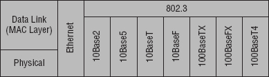
Figure 4.6 shows the IEEE 802.3 and original Ethernet Physical layer specifications.
When designing your LAN, it's really important to understand the different types of Ethernet media available to you. Sure, it would be great to run Gigabit Ethernet to each desktop and 10Gbps between switches, as well as to servers. Although this is just starting to happen, justifying the cost of that network today for most companies would be a pretty hard sell. But if you mix and match the different types of Ethernet media methods currently available instead, you can come up with a cost-effective network solution that works great!
The Electronic Industries Association and the newer Telecommunications Industry Alliance (EIA/TIA) together form the standards body that creates the Physical layer specifications for Ethernet. The EIA/TIA specifies that Ethernet use a registered jack (RJ) connector on unshielded twisted-pair (UTP) cabling (RJ-45). However, the industry is calling this just an 8-pin modular connector.
Each Ethernet cable type that is specified by the EIA/TIA has something known as inherent attenuation, which is defined as the loss of signal strength as it travels the length of a cable and is measured in decibels (dB). The cabling used in corporate and home markets is measured in categories. A higher-quality cable will have a higher-rated category and lower attenuation. For example, Category 5 is better than Category 3 because Category 5 cables have more wire twists per foot and therefore less crosstalk. Crosstalk is the unwanted signal interference from adjacent pairs in the cable.
Here are the original IEEE 802.3 standards:
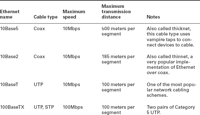
10Base2 This is also known as thinnet and can support up to 30 workstations on a single segment. It uses 10Mbps of baseband technology, coax up to 185 meters in length, and a physical and logical bus with Attachment Unit Interface (AUI) connectors. The 10 means 10Mbps, and Base means baseband technology—a signaling method for communication on the network—and the 2 means almost 200 meters. 10Base2 Ethernet cards use BNC (British Naval Connector, Bayonet Neill-Concelman, or Bayonet Nut Connector) and T-connectors to connect to a network.
10Base5 Also known as thicknet, 10Base5 uses a physical and logical bus with AUI connectors, 10Mbps baseband technology, and coax up to 500 meters in length. You can go up to 2,500 meters with repeaters and 1,024 users for all segments.
10BaseT This is 10Mbps using Category 3 UTP wiring. Unlike on 10Base2 and 10Base5 networks, each device must connect into a hub or switch, and you can have only one host per segment or wire. It uses an RJ-45 connector (8-pin modular connector) with a physical star topology and a logical bus.
Each of the 802.3 standards defines an AUI, which allows a one-bit-at-a-time transfer to the Physical layer from the Data Link media-access method. This allows the MAC address to remain constant but means the Physical layer can support both existing and new technologies. The original AUI interface was a 15-pin connector, which allowed a transceiver (transmitter/receiver) that provided a 15-pin-to-twisted-pair conversion.
There's an issue, though—the AUI interface can't support 100Mbps Ethernet because of the high frequencies involved. So basically, 100BaseT needed a new interface, and the 802.3u specifications created one called the Media Independent Interface (MII) that provides 100Mbps throughput. The MII uses a nibble, which you of course remember is defined as 4 bits. Gigabit Ethernet uses a Gigabit Media Independent Interface (GMII) and transmits 8 bits at a time.
802.3u (Fast Ethernet) is compatible with 802.3 Ethernet because they share the same physical characteristics. Fast Ethernet and Ethernet use the same maximum transmission unit (MTU) and the same MAC mechanisms, and they both preserve the frame format that is used by 10BaseT Ethernet. Basically, Fast Ethernet is just based on an extension to the IEEE 802.3 specification, and because of that, it offers us a speed increase of 10 times 10BaseT.
Here are the expanded IEEE Ethernet 802.3 standards, starting with Fast Ethernet:
100BaseTX (IEEE 802.3u) 100BaseTX, most commonly known as Fast Ethernet, uses EIA/TIA Category 5 or 5e or 6 and UTP two-pair wiring. It allows for one user per segment up to 100 meters long (328 feet), and uses an RJ-45 connector with a physical star topology and a logical bus.
100BaseT and 100BaseTX: What's the difference? 100BaseT is the name of a group of standards for Fast Ethernet that include 100BaseTX. Also included are 100BaseT4 and 100BaseT2. The same can be said about 1000BaseT and 1000BaseX.
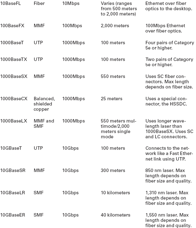
100BaseFX (IEEE 802.3u) Uses 62.5/125-micron multimode fiber cabling up to 412 meters long and point-to-point topology. It uses ST and SC connectors, which are media-interface connectors.
Ethernet's implementation over fiber can sometimes be referred to as 100BaseTF even though this isn't an actual standard. It just means that Ethernet technologies are being run over fiber cable.
1000BaseCX (IEEE 802.3z) Copper twisted-pair called twinax (a balanced coaxial pair) that can run only up to 25 meters and uses a special 9-pin connector known as the High-Speed Serial Data Connector (HSSDC).
1000BaseT (IEEE 802.3ab) Category 5, four-pair UTP wiring, and up to 100 meters long (328 feet).
1000BaseTX Category 5, two-pair UTP wiring up to 100 meters long (328 feet). Not used, and has been replaced by Category 6 cabling.
1000BaseSX (IEEE 802.3z) The implementation of Gigabit Ethernet runs over multimode fiber-optic cable instead of copper twisted-pair cable and uses short wavelength laser. Multimode fiber (MMF), using 62.5- and 50-micron core, utilizes an 850 nanometer (nm) laser and can go up to 220 meters with 62.5-micron; 550 meters with 50-micron.
1000BaseLX (IEEE 802.3z) Single-mode fiber that uses a 9-micron core, 1,300 nm laser, and can go from 3 km up to 10 km.
10GBaseT 10GBaseT is a standard created by the IEEE 802.3an committee to provide 10Gbps connections over conventional UTP cables (Category 5e, 6, or 7 cables). 10GBaseT allows the conventional RJ-45 used for Ethernet LANs. It can support signal transmission at the full 100-meter distance specified for LAN wiring. If you need to implement a 10Gbps link, this is the most economical way to go!
10GBaseSR An implementation of 10 Gigabit Ethernet that uses short-wavelength lasers at 850 nm over multimode fiber. It has a maximum transmission distance of between 2 and 300 meters (990 feet), depending on the size and quality of the fiber.
10GBaseLR An implementation of 10 Gigabit Ethernet that uses long-wavelength lasers at 1,310 nm over single-mode fiber. It also has a maximum transmission distance between 2 meters and 10 km, or 6 miles, depending on the size and quality of the fiber.
10GBaseER An implementation of 10 Gigabit Ethernet running over single-mode fiber that uses extra-long-wavelength lasers at 1,550 nm. It has the longest transmission distances possible of all the 10 Gigabit technologies: anywhere from 2 meters up to 40 km, again depending on the size and quality of the fiber used.
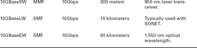
10GBaseSW 10GBaseSW, as defined by IEEE 802.3ae, is a mode of 10GBaseS for MMF with an 850 nm laser transceiver and a bandwidth of 10Gbps. It can support up to 300 meters of cable length. This media type is designed to connect to SONET equipment.
10GBase-LW 10GBaseLW is a mode of 10GBaseL supporting a link length of 10 km on standard single-mode fiber (SMF) (G.652). This media type is also designed to connect to SONET equipment.
10GBaseEW 10GBaseEW is a mode of 10GBaseE supporting a link length of up to 40 km on SMF based on G.652 using optical-wavelength 1,550 nm. This is another media type designed to connect to SONET equipment.
If you want to implement a network medium that is not susceptible to electromagnetic interference (EMI), fiber-optic cable provides a more secure, long-distance cable that is not susceptible to EMI at high speeds like UTP is.
Table 4.4 summarizes the cable types.
An advantage of 100BaseFX over 100BaseTX is longer cable runs, but 100BaseTX is easier to install.
I know there's a lot of information to remember about the various Ethernet and fiber types used in today's networks, but for the CompTIA Network+ exam, you really need to know them. Trust me, I haven't inundated you with unnecessary information!
![]()
Deploy the Appropriate Wired Connectivity Standard
You have been tasked with installing wiring to handle the new networking technologies of 1000Mbps to the desktop and Voice over IP (VoIP), with 10Gbps between the access switches and the core switches. What cabling do you consider installing in order to accomplish this in a cost-effective manner?
First, you need to verify your distances. Since this will not include any wireless stations, you need to double-check the distances to each station and make sure the phone is within 100 meters (or closer) for connectivity to your access switches.
Once you have your distances verified at 100 meters or less, you can use UTP wiring to the stations and phones and possibly even connect the stations into the back of the phones. Most phones have switches included, so this means you only need to run one Category 5e or better 1000BaseT four-pair cable to each cubicle or office.
For your connections from your access switches to your core switches, you can use 10GbaseT if your runs are 100 meters or less, or you can use 10GbaseSR, which allows runs up to 300 meters using multimode fiber.
Ethernet over Other Standards (IEEE 1905.1-2013)
IEEE 1905.1-2013 is an IEEE standard that defines a convergent digital home network for both wireless and wireline technologies. Some the technologies include IEEE 802.11 (Wi-Fi), IEEE 1901 (HomePlug, HD-PLC) powerline networking, IEEE 802.3 Ethernet, and Multimedia over Coax (MoCA). The 2905.1-2013 was published in April 2013. The IEEE 1905.1 Standard Working Group is sponsored by the IEEE Power Line Communication Standards Committee (PLCSC). The idea behind the 1905.1 technology standards is simple setup, configuration, and operation of home networking devices using both wired and wireless technologies. This will take advantage of the performance, coverage, and mobility benefits of multiple interfaces (Ethernet, Wi-Fi, Powerline, and MoCA), which enables better coverage and throughput in every room for both wireless and fixed devices.
- Ethernet over Power Line
- Ethernet over HDMI
Ethernet over Power Line
In February 2011, the IEEE finally published a standard for Broadband over Power Line (BPL) called IEEE 1901, also referred to as Power Line Communication (PLC), or even Power Line Digital Subscriber Line (PDSL). Although this technology has been available for decades in theory, without an IEEE standard it was just not adopted as an alternative to other high-speed media.
However, it is highly likely that this technology will really start to see some traction, especially from the power companies who will be able to gather data from every device in your house and specifically tell you how much power is being used by your refrigerator, washers and dryers, and especially your computer and televisions, among all the other devices plugged into a wall power outlet.
In the future, BPL will allow you to just plug a computer into a wall power socket and have more than 500Mbps for up to 1,500 meters.
Near my home in Boulder, Colorado, Xcel Energy is using BPL in combination with radio links for its SmartGridCity pilot project, which will send data from power meters, hot water heaters, thermostats, and more.
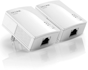
An example of an adaptor is shown in Figure 4.7.
This technology can be used to deliver Internet access to the home as well. For a computer (or any other device), you would simply need to plug a BPL modem into any outlet in an equipped building to have high-speed Internet access. The basic BPL installation is shown in Figure 4.8.
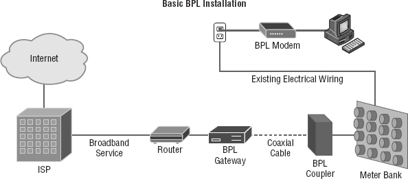
After the gateway is connected through the coupler to the meter bank for the building, any electrical outlet can be used with the BPL modem to receive the ISP connection to the Internet. Challenges that still exist include:
- The fact that power lines are typically noisy.
- The frequency at which the information is transmitted is used by shortwave and the unshielded power lines can act as antennas, thereby interfering with shortwave communications.
Ethernet over HDMI
HDMI Ethernet Channel technology consolidates video, audio, and data streams into a single HDMI cable, combining the signal quality of HDMI connectivity with the power and flexibility of home entertainment networking.
Figure 4.9 shows how a possible home entertainment network will look before and after Ethernet over HDMI is implemented.

It incorporates a dedicated data channel into the HDMI link, enabling high-speed, bi-directional networking at up to 100Mbps.
Armed with the basics covered in the chapter, you're equipped to go to the next level and put Ethernet to work using various network devices. But to ensure that you're really ready, read the summary, go over the exam essentials, and do the written lab and review questions for this chapter!
Summary
In this chapter, you learned the fundamentals of Ethernet networking, how hosts communicate on a network, and how CSMA/CD works in an Ethernet half-duplex network.
I also showed you the differences between half- and full-duplex modes.
I finished the chapter with a description of the common Ethernet cable types used in today's networks. And by the way, you'd be wise to study that section really well!
Exam Essentials
Understand basic Ethernet communication. Know how hosts use hardware addresses to communicate on an Ethernet LAN.
Understand Ethernet addressing. Know the hexadecimal addressing scheme used to create an Ethernet address.
Understand binary, decimal, and hexadecimal addressing. Know the different addressing types, and also use the written lab to practice your conversions.
Written Lab
In this section, you will write in the answers to the following conversion tables. You can find the answers in Appendix A.
- Convert from decimal IP address to binary format.
Complete the following table to express 192.168.10.15 in binary format.
Complete the following table to express 172.16.20.55 in binary format.

Complete the following table to express 10.11.12.99 in binary format.

- Convert the following from binary format to decimal IP address.
Complete the following table to express 11001100.00110011.10101010.01010101 in decimal IP address format.
Complete the following table to express 11000110.11010011.00111001.11010001 in decimal IP address format.
Complete the following table to express 10000100.11010010.10111000.10100110 in decimal IP address format.

- Convert the following from binary format to hexadecimal.
Complete the following table to express 11011000.00011011.00111101.01110110 in hexadecimal.
Complete the following table to express 11001010.11110101.10000011.11101011 in hexadecimal.

Complete the following table to express 10000100.11010010.01000011.10110011 in hexadecimal.


Review Questions
You can find the answers to the review questions in Appendix B.
- On an Ethernet switched network, what address does one host computer use to communicate with another?
- IP address
- MAC address
- Street address
- HUB address
- Which of the following can run full duplex and achieve 200Mbps with Cat 5e cable?
- 100BaseF
- 100BaseTX
- 1000BaseF
- 1000BaseT
- How many devices in a collision domain have to listen when a single host talks?
- 2
- 3
- 1
- All
- If you are using a cable medium called 10Base2, what does this mean?
- That you are running Ethernet over HDMI
- That you are running Ethernet over fiber
- That you are running Ethernet over thicknet
- That you are bundling multiple connections
- That you are really old and using thinnet coax for your LAN medium
- What network access control method helps devices share the bandwidth evenly without having two devices transmit at the same time on the network medium?
- TCP/IP
- CSMA/CD
- HTTPS
- TFTP
- What is the maximum distance of 10GBaseSR?
- 100 meters (328 feet)
- 302 meters (990 feet)
- 305 meters (1000 feet)
- 1,593 km (6 miles)
- How many wire pairs are used with half duplex?
- 2
- 1
- 4
- None of the above
- How many wire pairs are used with 100BaseT full duplex?
- 2
- 1
- 4
- A or C
- What is the maximum distance of 10GBaseLR?
- 1 mile
- 3 miles
- 6 miles
- 25 miles
- What is the effective total throughput increase with a full-duplex connection?
- None
- Twice as much
- Four times as much
- Ten times as much
- What device can you not use full-duplex communication with?
- Host
- Hub
- Switch
- Router
- What is the decimal equivalent of this binary number: 11000000.10101000.00110000.1111 0000?
- 192.168.48.192
- 192.168.48.240
- 192.168.64.224
- 192.168.32.248
- Which IEEE standard is used for Ethernet over Power Lines?
- 802.3p
- 1901
- 802.16
- 1918
- How is the decimal value 10 represented in binary?
- 1000
- 1001
- 1010
- 1011
- What is the decimal value for the binary number 11101000?
- 128
- 194
- 224
- 232
- What is the decimal number 10 in hexadecimal?
- 9
- A
- C
- B
- How many bits is a MAC address?
- 16
- 32
- 48
- 64
- What is the maximum distance of 1000BaseT?
- 100 meters (328 feet)
- 128 meters (420 feet)
- 1000 meters (3280 feet)
- 1,024 meters (3360 feet)
- What is the purpose of the Frame Check Sequence (FCS) in an Ethernet frame?
- Error correction
- Error detection
- Error recovery
- Creating errors
- What does the Base mean in 100BaseTX?
- Broadband
- 100Mbps
- Baseband
- Twisted-pair at 100Mbps