
Virtualization
In this chapter, you will learn how to
• Describe storage virtualization
• Utilize tape virtualization in a practical business setting
• Explain how host virtualization makes it easier to work with storage
• Describe how virtualization is implemented within an array
• Differentiate between virtualization methods used on networks
Chapters 1 through 4 provided a comprehensive overview of storage technologies and principles. Chapter 5 begins the practical exploration of managing storage resources by using storage virtualization. Storage virtualization is the logical abstraction of a physical resource that uses hardware, software, and other technologies to pool or aggregate disparate storage resources such as disks, tapes, logical volumes, or arrays. As part of this process, physical storage is seen as a centralized virtual resource that can be referenced, used, and managed in differing forms allowing for increased scalability and data access. Storage virtualization provides a robust platform for data archiving, backup, and disaster recovery, along with a means for dynamic or on-demand utilization and optimization of storage resources.
What does that mean for storage professionals? Data, and the information derived from it, can be an organization’s greatest asset but also its greatest challenge. Legal requirements for data retention periods, the need for data to be accessible whenever and wherever users happen to be, and the requirement for securing data all make managing the sheer volume of data captured, stored, and made available by a company a task often rivaling the operation of its primary lines of business. Successful data management is predicated on striking a balance between a complex mix of architectures, policies, procedures, and technology.
In a perfect world, all these policies/procedures, architectures, and technologies would be compatible, offering a high degree of interoperability and seamless integration throughout the storage fabric. In reality, a company’s data and the technology it deploys is typically mixed and needs to interact with other entities that, in turn, deploy differing standards for managing, accessing, and storing data. Data resource management becomes even more complex given that these data and resources may be geographically dispersed across a region, nation, or geopolitical borders. Storage virtualization offers the potential for providing access without users having to understand the underlying complexities of the technology. Storage virtualization also makes it easier to perform migration and management of storage resources in this fast-paced, volatile environment.
In addition to virtualization’s ease of management, virtualization enables businesses to better utilize their existing storage technology. Underutilization of storage, data protection, and its availability remain critical issues in the successful management of information systems. Storage virtualization offers an enterprise the real-time capability to dynamically manage and optimize storage resources and data regardless of the complexity, location, or mix of technologies.
Types of Storage Virtualization
Given the many competing vendor-based views of what constitutes storage virtualization, the Storage Networking Industry Association (SNIA) shared storage model provides a generally accepted way of defining and understanding storage virtualization. SNIA defines storage virtualization as follows:
• The act of abstracting, hiding, or isolating the internal functions of a storage subsystem or service from applications, host computers, or general network resources for the purposes of enabling application and network-independent management of storage or data.
• The application of virtualization to storage services or devices for the purposes of aggregating functions or devices, hiding complexity, or adding new capabilities to lower-level storage resources.
The Shared Storage Model (SSM), shown in Figure 5-1, was created in 2001 as a four-layer model similar to the Open System Integration (OSI) Model, where the lowest layer defines the physical aspects of storage virtualization and the highest layer forms the application layer. The SNIA SSM is also similar to the OSI Model in that it has not been implemented by a vendor. Rather, it is useful as a tool for understanding how shared storage works. It also provides a vendor-neutral way to discuss storage system functionality by using the same vocabulary.

Figure 5-1 SNIA Shared Storage Model
At the top of the SNIA SSM is the applications layer, layer 4. This is the reason for the storage system in the first place, and it rests at the top of the model because it is the product of the layers underneath it.
Layer 3 is the file/record layer. This layer consists of the database and file systems that support the application. This layer is responsible for organizing the information required by the application, and it directly interfaces with the application. For example, an application may query a database for information stored in tables, or an application could request a file from a file system. This file system may be local to the device, or it could reside on a network attached storage (NAS) server.
Layer 2 is the block aggregation layer, responsible for connecting to storage. It has three subelements: device, network, and host. Device refers to a direct attached storage (DAS) device that contains the storage accessed by the layer. Network includes storage area network (SAN) storage resources, and host refers to storage located inside the host machine or server.
Layer 1 is the storage devices layer, which handles striping, mirroring, parity, and read and write operations. The data provided from layer 2 needs to be stored onto media, such as disk or tape, as bits and bytes that are grouped and referenced into blocks.
SNIA has also developed a model for storage virtualization. The SNIA Storage Virtualization Taxonomy identifies five types of storage virtualization. They are briefly introduced here and covered more extensively in subsequent sections of this chapter: tape, disk, block, file system, and file/record.
The first type is tape virtualization. Tape virtualization takes the form of virtual tapes (VTs), virtual tape libraries (VTLs), and tape library virtualization (TLV).
Second are disks. Disks use virtualization to map logical addresses to physical addresses. Cylinder, head, and sector (CHS) is a method for accessing data on a physical disk. The head information describes which platter and side the data resides on, while the cylinder information locates the track on that platter. Lastly, the sector addresses the area within that track so that the head can be positioned to read or write data to that location. CHS physical data is allocated by disk firmware to virtual locations on the medium through the use of logical block addressing (LBA). LBA is a way of referencing a location on a disk without a device having knowledge of the physical disk geometry.
Whereas a controller identifies data based on CHS, logical volumes virtually map blocks using LBA. LBA provides a system with the number of blocks contained on the drive, while the system keeps track of the data contained on each block. It requests the data by block number, and the drive then maps the block to a CHS and retrieves the data.
Next comes block virtualization. Block virtualization is an abstraction of physical storage to logical partitions independent of storage structure, allowing several physical disks to be accessed through a single virtual/logical interface. This results in greater flexibility in storage management in how and where data is stored.
Fourth, file or record virtualization is used to dynamically allocate infrequently used files or records to secondary storage while caching more actively used files on primary storage. When implemented, file-based virtualization presents storage to a device such as a remote share using protocols such as Network File System (NFS) or Common Internet File System (CIFS), whereas block storage is presented to a device as local storage using protocols such as Fiber Channel Protocol (FCP) or Internet Small Computer System Interface (iSCSI).
Lastly, file system virtualization allows a file system to share remote or network attached logical partitions where the location is transparent to the applications, reading and writing to and from the storage.
Tape Virtualization
Because of the onslaught of vendor products and competing taxonomies, getting to the heart of what constitutes tape virtualization may seem frustrating. The abundant availability and deployment of high-performance, high-capacity tape media and drives seem to position one storage technology against the other. Tape media remains a mainstay of computing. While prices have steadily declined against the increased capacity and performance of tape, it still remains a serial technology. The staying power of tape can be seen in its portability, therefore making it the perfect media for data archiving, migration, backup, and rapid disaster recovery. Tape virtualization uses a combination of disk drives and tape media to augment three different tape virtualization techniques:
• Virtual tape This is an interface that emulates the way a physical tape would operate, but data is stored on another medium such as a disk.
• Virtual tape library Disks are used as replacements for tape libraries. They emulate a collection of tapes that can be automatically loaded and inventoried.
• Virtual tape server Intelligent devices and software coordinate storage onto virtual resources.
Virtual Tape
Storage virtualization using the virtual tape method provides a dynamic platform for archiving, backup, and disaster recovery. All of these functions can be performed as background operations, concurrently or in parallel, thus minimizing tape failures and media errors since the data is stored on disk instead. Disks do not suffer from the limitations tapes have of needing to access data sequentially. In this way, VT provides a means of offsetting the serial nature of accessing data or files from tape storage. Disks are used as caches or temporary holding areas for concatenated data sets, fostering rapid data transfers and access to target tape media. The data comprising virtual tapes can be consolidated through deduplication so that identical data is stored only once. Physical tapes may have unused space at the end of a tape once a job runs, but VTs only consume the space that is required by the backup job. For example, 100GB of data is written daily to an LTO3 tape with an uncompressed capacity of 400GB, and then the tape is changed for another; 300GB of the available space is wasted daily. However, utilizing VT, 100GB is written to a virtual LTO3 tape, but only 100GB is consumed on the storage. This results in better utilization of storage media.
The following steps outline the general process for creating VTs. The first step is to identify the media that will be used for creating the VTs. This could include disks, Redundant Array of Independent Disks (RAID) sets, or tapes. The speed of the media chosen will determine how quickly backups to VT can complete and how quickly they can be restored, while the capacity of the media will determine how many backups to VT can be taken before some backups must be overwritten. Avoid selecting media from a single source because if that single source, such as a single RAID array, is lost, all VTs will be lost as well.
Next, a storage pool is created using the resources identified in the previous step. The storage pool aggregates the storage available to the disks, tapes, or RAID sets within it so that it can be allocated as VT storage. Storage pools can be expanded with additional media later as needs change. To optimize the use of target tape media, it is necessary to determine the optimum size and density of the given tape media. These blocks or integrated file streams (IFSs) are placed in pools of storage. This method allows the size of the IFS to be determined dynamically or remain fixed.
Once a storage pool is created, VTs must be created from the storage pool. This is followed by the creation of an image catalog. An image catalog is created indicating the location of data within virtual volumes created on the disk. Lastly, assign the VTs to backup software that will write data to them as if they were physical tapes.
Virtual Tape Library
Specialized servers, devices, and software are used to create virtual tape libraries that reside on disk. The chief benefit of this scheme lies in its ability to emulate various tape formats and media while maximizing utilization of resources. Unlike tape, random data can be transferred to and accessed from disk technology much faster and then transferred to secondary tape storage if necessary. Figure 5-2 shows a VTL solution. Alternately, these disk-based virtual libraries can be used as an independent, stand-alone option. As an enterprise-level virtualization option, VTLs are typically implemented on RAID and other disk array platforms.

Figure 5-2 Sample VTL solution
 EXAM TIP A VTL solution could be as simple as a server with backup software that supports VTL. This would then write to local storage but treat it as tape from a recovery standpoint.
Virtual Tape Server
As with other forms of tape virtualization, virtual tape servers integrate disk and tape functionality to provide low-cost, high-performance storage and data management. Multiple files are stored on the virtual volume using volume stacking. A stacked volume can consist of a single or multiple logical volumes on a virtual tape server, as depicted in Figure 5-3. The virtual tape server library serves as the index indicating where files or data are stored on logical volumes. VTS technology allows for greater utilization of storage resources with deduplication. The data on VTS servers can be consolidated through deduplication so that identical data is stored only once. Multiple daily, weekly, or monthly backups of the same data store will result in many duplicate files, which would need to be written individually to tape, but can be written only once to a VTS device using deduplication. Once data has been stored on a VTS, it can then be archived to another site or eventually transferred to tape, if necessary, to provide additional backup redundancy.
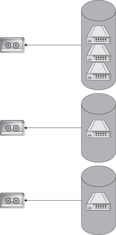
Figure 5-3 Virtual tape server
Network Data Management Protocol
Network Data Management Protocol (NDMP) is a protocol that allows devices to communicate with backup hardware such as tape devices directly without going through backup servers. This is more direct and can result in lower network bandwidth utilization, shorter backup times, and less hardware to maintain and support in the environment. Without NDMP, backups may need to be staged on another device before they are backed up, or restores may need to be performed on another volume before being copied to the production volume. With NDMP, devices such as NAS can issue backup or restore requests directly to the network attached backup device.
Disk Virtualization
Regardless of design or capacity, disk virtualization uses the firmware within a given drive to translate the physical locations or addresses of data on the disk’s CHS to LBA. Disk virtualization addresses the use of heterogeneous disk technologies often intermixed in an enterprise’s storage fabric. Disk virtualization provides an additional benefit of data protection and integrity through its ability to bypass defective blocks on the disk by mapping them to healthy logical block locations. Figure 5-4 shows the mapping of LBA to CHS.

Figure 5-4 LBA to CHS mapping
Block Virtualization
Block virtualization allows for logical volumes (LVs) to be created from storage that may consist of multiple drives and multiple RAID arrays. However, systems accessing block storage do not need to understand where and how access is provided in order to utilize it.
In this context, block virtualization facilitates nondisruptive data archiving, migration, backup, and recovery. The topic of block virtualization is best understood in terms of its relationship to storage area networks and network attached storage. Distributed storage assets are abstracted to provide a single logical portal for storage management and optimization. Block virtualization provides a translation layer in the SAN, between the hosts and the storage arrays. Multiple distributed physical disks can be mapped to a single logical volume or interface with block virtualization.
Addressing
Block virtualization works by addressing a single block of data using a unique identifier called a logical unit number (LUN). The LUNs for an entire drive are then mapped to virtual storage using an LBA. The LUN is capable of mapping single or multiple physical disks within a SAN environment. Storage assets (a logical volume created from one or more physical disks in a RAID set or array) are identified using LUNs and presented as a single logical storage component.
LBA represents an enhancement over traditional CHS addressing and was first introduced with the advent of SCSI disks. As a 28-bit scheme, LBA is capable of addressing disks in excess of 528MB by mapping CHS addresses on a disk or secondary storage. Storage locations are created and accessed via a linear sector address scheme beginning with zero, or LBA 0. Figure 5-5 shows how a LUN maps to physical space.

Figure 5-5 LUN mapping to physical space
EXAM TIP In SANs or RAID arrays, LUNs of physical disks are mapped via LBA to storage for an entire device.File Virtualization
File virtualization in a SAN environment overcomes the limitations of data and location dependencies where files are associated with specific servers. Network shares residing on different servers increase fragmentation and underutilization of storage capacity because each server is logically and physically independent. As a consequence, file access and migration can be disruptive because storage resources may have to be taken offline during reconfiguration. Quality of service (QoS) and service level agreements are compromised because applications and hosts will require path reconfiguration. However, file virtualization allows for a single namespace to be used for shared resources while the resources may be distributed to many servers behind the scenes.
EXAM TIP File virtualization namespaces can be redundantly created so that there is not a single point of failure by hosting them on multiple devices. The namespace mount point can be accessed from any server hosting it.In short, file virtualization provides a nondisruptive alternative for data access, migration, backup, and recovery. File virtualization provides location independence through the use of logical pools, which use logical rather than physical paths between storage resources, allowing for files to be stored where they can best be protected against loss and aggregated to save space.
Through the use of global namespaces, logical file paths are mapped to physical path names. The goal of a global namespace is to enable a single view of the NAS file system. In this way, transparent access to NAS resources is provided. Entire file systems can be seamlessly read from their former location and written to the new one. File virtualization can be implemented using stand-alone devices or integrated into the NAS or storage system itself.
File System Virtualization
Multiple file systems are aggregated into a single logical system. Users have access to data and storage resources from underlying transparent file systems. The following are types of file systems currently in use:
• SAN file system Enables sharing of the same copies of files stored on common storage media among multiple servers of different platforms.
• Local disk file system Enables the storage and retrieval of files on local storage. Files are stored in a hierarchical (tree) structure where file location and paths within the structure and naming conventions are specified by the local policies and the file system. A root directory is assigned to the top of each logical drive, and then files and folders can be placed underneath.
• Distributed file system (DFS) Provides the ability to logically group shares on multiple servers and to transparently link shares into a single, hierarchical namespace. Shared resources on a network are organized in a tree structure, as depicted in Figure 5-6.

Figure 5-6 Distributed file system
Resources can be in multiple sites; in some cases, resources are replicated to multiple locations, and the data is presented to users based on its availability and locality to the user, with the server closest to the user serving the data rather than traffic traversing slow links, as shown with the profiles share in Figure 5-7.

Figure 5-7 Distributed file system with multiple sites and replication
• Clustered file system (CFS) A distributed file system that runs concurrently on multiple NAS nodes. Clustering provides transparent access to all files on all homogeneous clustered nodes, regardless of the physical location of the file. The number and location of the nodes are transparent. System nodes must be similarly configured and from the same vendor.
File/Record
With file or record virtualization, files and directories are presented as a composite object with a single integrated file interface, but consisting of storage from one or more devices that are either locally attached or on the storage network. Location independence is achieved, allowing users, applications, and devices to access and manipulate files irrespective of where they are stored as if they were stored locally.
Host Virtualization
In server or host-based virtualization, LUNs from physical disks are aggregated into a larger primary LUN, which is seen as a single device by applications and users. This is accomplished through the use of logical volume managers (LVMs) integrated as part of stand-alone appliances or servers or as part of a privileged kernel of the host operating system. Since virtualization is done at the device or server level, existing paths and mechanisms for control are maintained. Data is dynamically routed, or multipathed, between shared storage. This form of virtualization is typically used with DAS, but can span multiple storage subsystems that are connected within a SAN.
LVM
LVMs create logical partitions capable of spanning single or multiple physical devices. Physical volumes (PVs) are then created within these partitions and are aggregated in volume groups (VGs). LUNs effectively provide logical volume management functionality such as mirroring, partition resizing, disk allocation, and striping. VGs are divided into logical groups (LGs) with designated mount points. Figure 5-8 illustrates the LVM concepts defined next.

Figure 5-8 LVM concepts
• Extents These are the basic building blocks of data and storage used to prevent disk fragmentation through the use of a marker that is placed to indicate the last write of 64-bit blocks (8 pages) of contiguous space that occurred for a file.
• Physical volume This is composed of extents.
• Logical volume This is the equivalent of a disk partition in non-LVM environments; it is seen as a centralized block device.
• Physical extent Each physical volume is divided into contiguous blocks of data. In a VG, PEs are identical in size to LEs in the VG.
• Logical extent Each logical volume is divided into equal-sized blocks of data.
• Volume group This is a large group of storage from which LVs can be created. PVs are aggregated into a singular unit.
LVM creation is achieved in the following steps:
1. Identify physical media to be deployed.
2. Create VG from PV.
3. Create LVs from the VG.
Virtual Provisioning
Virtual provisioning allows a logical unit to appear larger than its actual physical capacity. Dynamic storage allocation is derived from a pool of shared physical storage. In this context, virtual provisioning allows for the downstream addition of other storage devices while the thin pool is active. Thin provisioning is creating a logical volume that can grow as needed. To provision virtual storage, first allocate one or more RAID groups with sufficient capacity for the data you want to store. Next, create a pool, giving it a name, and then assign LUNs from the RAID groups you identified to the storage pool. Finally, allocate storage to hosts, specifying thin provisioning and using the storage pool.
EXAM TIP When thin LUNs are deleted, the capacity is reallocated to the shared pool either automatically or through a reclamation process.Implementing Host Virtualization
Several strategies exist to map logical extents into physical extents, including linear mapping, striped mapping, and snapshot. Each of these is described next and shown in Figure 5-9.

Figure 5-9 Mapping logical extents to physical extents
• Linear mapping This is the contiguous designation of a range of PEs to an area on an LV. For example, LEs 1–99 are mapped to PV1, and LEs 100–347 are mapped to PV2.
• Striped mapping LEs are interleaved across a number of PVs. In Figure 5-9, the odd LEs are on PV1, and the even LEs are on PV2.
• Snapshot This is an exact copy of an LG at a given point in time. Snapshots will be discussed in more detail in Chapter 7.
Array-Based Virtualization
Array-based, sometimes called storage-based or subsystem, virtualization uses a primary or master array to manage all input/output (I/O) for other arrays in the SAN. The intelligence for virtualization is embedded in some general-purpose servers as network appliances specially architected for the task. Both DAS and SAN storage can be accommodated.
One DAS can virtualize other directly attached DAS, as shown in Figure 5-10; a storage array can virtualize a DAS attached to it, as shown in Figure 5-11; or a storage array can virtualize another storage array, as depicted in Figure 5-12.

Figure 5-10 DAS virtualized by a DAS

Figure 5-11 DAS virtualized by a storage array

Figure 5-12 Storage array virtualized by another storage array
A primary storage controller manages metadata and pooling. Additional storage may be directly attached, adding greater functionality to the storage fabric. Since there are no host dependencies, array-based virtualization is ideal for heterogeneous operating systems, applications, or devices.
Array and block-based virtualization are often combined to take advantage of the robust performance of RAID and LVM versatility. Host-based LVMs can work in conjunction with several RAID LUNs to create virtual volumes that span multiple disk arrays. Load balancing, alternate routing, striping, and mirroring are a few of the functions supported by this block-array virtualization combination.
There are five types of block-array virtualization engines:
• Heterogeneous arrays (controller based) include physical volumes in the array and on external volumes on external arrays.
• Homogeneous arrays (controller based) include physical volumes just in the array with the controller.
• Heterogeneous external virtualization appliances maintain the maps for multiple heterogeneous arrays in the appliance.
• Heterogeneous external virtualization appliances maintain the maps for multiple heterogeneous arrays in the appliance and in the LAN switch.
• Server-based virtualization offers a solution for operating systems and applications that support differing file systems.
The rationale for combining array and block-based virtualization lies in the robust performance of RAID technology and the flexibility of host LVMs. LVMs can work with RAID LUNs to create virtual volumes that span multiple arrays. Load balancing, alternate routing, mirroring, and striping are other functions supported by the array–host– based virtualization combination.
Virtual Provisioning of the Array
To provision an array for virtualization, the array you want to virtualize must be connected to the controllers of the array that is virtualizing it. Each vendor will have its own specification for how to set up the pairing of the two arrays. Once this is complete, one array will provide the front-end I/O for the arrays that are virtualized through it. One or more arrays can be virtualized in this fashion.
Implementing Array-Based Virtualization
When implementing array-based virtualization, it is important to know whether the product you want to virtualize is supported by the vendor. Each array vendor that supports array virtualization keeps a list of the models of arrays that can be virtualized. You will also need to make sure your master array has the front-and back-end capacity to handle the I/O that will be going through it. Virtualizing other arrays is similar to adding more storage shelves to the array in terms of the resources required to interface between the storage.
Network Virtualization
Optimization of network resources is the primary goal of network storage virtualization. The complexity of underlying network resources—servers, nodes, paths, and applications—are abstracted into a consolidated virtual focal point for storage management. The physical infrastructure, services, and provisioning are dynamically orchestrated to provide enterprise-wide network storage management and optimization.
Through the use of virtual aggregation and provisioning, multiple virtual storage networks can be combined to form a larger logical resource or segregated into smaller, special-purpose virtual storage domains. Network virtualization is designed to provide network optimization, including better data migration and integrity, increased throughput and performance, agility, scalability, and data integrity. All network servers and services are treated as a singular pool of resources, which may be used regardless of its location or composition of physical components.
EXAM TIP Network virtualization is especially suited for networks experiencing rapid expansion or frequent spikes in latent demand.Concepts
The following concepts are provided to facilitate a deeper understanding of network storage virtualization:
• Abstraction This is the underlying complexity of a physical network; its processes and resources are rendered transparent by creating a logical representation.
• Aggregation Using in-band or out-of-band techniques, physical network resources are logically grouped into a single virtual resource.
• Dynamic multipathing (DMP) This offers cross-platform I/O optimization of heterogeneous storage and network resources.
• Isolation Isolating logical partitions provides a mechanism for maintaining storage integrity and performance optimization. Security breaches, bottlenecks, or suboptimal nodes can be bypassed or segregated so that the overall continuity and functioning of the network is not compromised.
• Partitioning Logical partitions can be created and dynamically configured to meet system or user requirements. Servers, protocols, and network infrastructure can be combined to meet changing business requirements.
Methods
There are two methods for implementing network storage virtualization: in-band and out-of-band. In-band network storage virtualization is implemented in the data path. Both data and flow control share the same path, as shown in Figure 5-13. Network appliances or devices provide flow control or I/O translation throughout the storage network; in-band provisioning introduces overhead that can contribute to latency and less-than-optimal network performance within a SAN as I/O requests are intercepted and mapped to physical storage locations.

Figure 5-13 In-band storage virtualization
Out-of-band network storage virtualization, illustrated in Figure 5-14, separates data and flow control onto separate channels. Controllers handle flow control processes, such as I/O routing and other control functions, allowing the maximum utilization of available bandwidth and storage. By separating the control functions from the paths where data travels, the latency characteristic of in-band network storage virtualization is avoided.

Figure 5-14 Out-of-band storage virtualization
Aside from issues related to overhead and latency, in-band and out-of-band network virtualization share the same general benefits, including the following:
• Optimization of SAN utilization and performance
• Storage management is off-loaded from the host
• Interoperability and multivendor support
• A consolidated virtual platform for network storage management
VSAN
A virtual storage area network (VSAN) is a logical partition within a SAN where zoning is used to segment connected devices and resources of a physical network into isolated virtual storage area networks. Communications are restricted to the virtual domains created by zoning. Zoning allows each VSAN to maintain its own services and name server, and it reduces the impact fabric changes have on devices and equipment since fabric changes need to be made only to devices within the same VSAN. Consequently, zone names can be reused as long as they reside within a different VSAN on the same SAN. Figure 5-15 shows three VSANs. One of the VSANs is spread across two regions with another VSAN in between. Data, however, flows between the VSAN transparently to the devices with the VSAN.

Figure 5-15 VSANs
EXAM TIP Without a VSAN, zone names would need to be unique across the entire SAN.• Logical switch Logical switches can comprise a whole or part of a physical switch in segments of a VSAN. In concept, it is similar to Ethernet VLANs (discussed later in this section) where each port on a switch can be assigned to a logical switch. Communication between logical switches occurs through an extended ISL (XISL) if the communication passes through one or more physical switches that have multiple logical switches on them. Otherwise, logical switches are connected through standard ISLs.
• Logical fabric This is another name for a VSAN.
LSAN
A logical storage area network (LSAN) spans multiple physical fabrics. Fibre Channel routers (FCRs) are used to allow specific devices from these autonomous virtual fabrics to communicate while maintaining independence from associated physical fabrics. The paths between the LSAN may be within the local fabric or may span a single or multiple FCRs. Backbone (BB) fabrics may be combined with these FCRs to form what is referred to as meta-SANs. Meta-SANs consist of all logically partitioned storage, fabrics, heterogeneous routers, devices, and other LSANs.
Routers are connected to the fabric through ports on FCRs or bridges. In this way, multiswitch fabrics are created. The Fibre Channel port types were discussed in Chapter 3, but these plus additional ports are used on FCRs and bridges. The following is a list of Fibre Channel port names, including those from Chapter 3:
• A bridge port (B-port) connects an FC switch to a bridge.
• A diagnostic port (D-port) is used to troubleshoot problems with connectivity between switches.
• An expansion port (E-port) is used to connect two switches together to form an ISL.
• An external port (EX-port) is only used on FC routers to connect to FC switches. FC switches use an E-port to connect to the router’s EX-port.
• Fabric ports (F-ports) are ports on a switch that are used to connect to end devices. The end devices use N-ports to connect to the switch’s F-port.
• A fabric loop port (FL-port) is used in the Fibre Channel arbitrated loop (FC-AL) topology and it connects to end devices in much the same way as an F-port would in the FC-SW topology.
• Generic ports (G-ports) allow more flexibility in an FC switch because they can operate as an F-port or an E-port depending on what is plugged into them. G-ports are used in the FC-SW topology.
• Node ports (N-ports) are ports used by a node in the FC-SW topology. N-ports connect to F-ports on the FC switch.
• A node loop port (NL-port) is a port used by a node in the FC-AL topology. NL-ports connect to FL-ports on the FC-AL switch.
• A trunking E-port (TE-port) is used to connect to other FC switches. It differs from an E-port in that VSAN information can be sent over the port. For example, if two switches are connected with TE-ports and three VSANs span the two switches, information for each of the VSANs can traverse the TE-port. To each VSAN, the port appears to be an E-port, and each VSAN will not be able to see the traffic for other VSANs.
• Universal ports (U-ports) allow more flexibility in an FC switch because they can operate as an FL-port or an NL-port depending on what is plugged into them. U-ports are used in the FC-AL topology.
• A VE-port is an E-port that is used in FCIP.
• A VEX-port is an EX-port used in FCIP.
VLAN
Virtual local area networks are based on the Institute of Electrical and Electronic Engineers (IEEE) 802.1q standard. A VLAN is a logical grouping of ports on a switch that forms a single broadcast domain. Media Access Control (MAC) addresses are divided into logical groups where only members of the virtual group are able to exchange data or communicate. Frames are tagged with the address of the group to which they belong. When a frame is sent to other ports, the hardware copies the frame only if it is configured with the VLAN number within the frame.
VLANS can be implemented as either a group of physical ports (layer 1), a group of MAC addresses (layer 2), or an IP subnet (layer 3).
• Layer 1 VLAN The layer 1 VLAN is a group of physical ports, referred to as port switching. It requires a router to be used to access the originating server. When users are relocated, they are assigned a new subnet and IP address.
• Layer 2 VLAN The layer 2 VLAN is a group of MAC addresses. It supports user mobility because LANs are defined by a list of MAC addresses. The protocol manages all MAC address changes, making it possible for clients and servers to always be on the same backbone, regardless of location.
• Layer 3 VLAN The layer 3 VLAN is an IP subnet or virtual subnet. The MAC protocol (type and subnet fields) is used to specify VLAN membership in this form of VLAN. Multiprotocol nodes can span multiple VLANs, and packets are tagged with a VLAN in addition to an IP address so that they can be delivered to the appropriate VLAN.
NPIV
N-ports and their associated N-port IDs, covered in Chapter 3, are used by end devices to connect and identify themselves on an FC fabric. N-port ID virtualization (NPIV) allows multiple N-port IDs to reside on one physical N-port. NPIV is commonly used on hypervisors, which are servers that host multiple virtual machines. NPIV allows each virtual machine on a hypervisor to have its own N-port ID that can be associated with logical units on the SAN. Hypervisors commonly have redundant ports, so NPIV would be used to provide each virtual machine with an N-port ID from each redundant physical port so that each would have a redundant connection to storage.
NPIV allows a single HBA, or target port, on a storage array to register multiple worldwide port names (WWPNs) and N-port identification numbers. This allows each virtual server to present a different worldwide name to the SAN, allowing each virtual server to see only its own storage.
NPIV requires both the switch and HBA to be NPIV capable. N-port initialization when using NPIV would start with the N-port sending a fabric discovery (FDISC) request to the login server (address FFFFFE) to obtain an additional address. Next, it sends a port logon request called a PLOGI to the name server (address FFFFFC) to register this additional address with the name server, followed by an SCR to the fabric controller (address FFFFFD) to register for state change notifications. This process is then repeated for all N-port IDs on the physical N-port.
Provisioning the Logical Fabric
Logical fabrics are provisioned by assigning a fabric ID to the VSAN. Physical FC switches, or logical switches within physical FC switches, differentiate traffic and send it to ports based on the fabric ID they belong to. Traffic must be routed to communicate between VSANs. This can be achieved with a switch, router, or director that is virtual fabric capable.
Chapter Summary
Storage virtualization in its many incarnations was the focus of this chapter. Several general and industry-supported definitions of storage virtualization were provided as an entry point to the maze of differing perspectives that has come to characterize storage virtualization. The flow of the chapter’s discussion was organized into three broad threads:
• The rationale and drivers for storage virtualization
• What is being virtualized
• The level or layer being virtualized
The rationale and primary drivers for storage virtualization are the need to deploy transparent, interoperable, enterprise-class storage virtualization. Data integration and data migration concepts were discussed as the primary challenges to this end. As previously noted, the proliferation of proprietary, heterogeneous storage virtualization schema, products, taxonomies, and implementations make it difficult to frame a coherent picture of just what constitutes storage virtualization.
Two broad but generally accepted definitions of storage virtualization from SNIA were presented, along with the SNIA Shared Storage Model and the SNIA Storage Virtualization Taxonomy, offering a simple but comprehensive lens through which storage virtualization can be viewed.
The focus of the chapter then shifted to “what” is being virtualized. Several different forms of storage virtualization were presented. They include tape virtualization, disk virtualization, block virtualization, and file/record virtualization.
Tape virtualization is performed by emulating tape resources so that backup software interfaces with the virtual tape, just as it would with a physical tape. Multiple VTs can be presented as a virtual tape library, which may use a storage array as the destination for the data, but the backup software treats it as if it were writing to tape. A server that provides VT services is known as a virtual tape server.
In disk virtualization, physical data is allocated by disk firmware to virtual locations on the medium through the use of logical block addresses. The storage system does not need to understand the internal disk mechanics of exactly where the data is stored on the physical disk to read and write data from the drive. This frees up the system from having to manage this type of activity and makes it easier to write software or operating systems that utilize storage.
Block virtualization is an abstraction of physical storage to logical partitions, independent of storage structure, allowing several physical disks to be accessed through a single virtual/logical interface. Block storage is presented to a node, such as a server or workstation, as local storage, and the system can interface with it as it would with disks that were located internally, but the data exists on a storage array. Typically, protocols such as Fibre Channel Protocol or Internet Small Computer System Interface are used to provide block storage to nodes.
File system virtualization allows a file system to share remote or network attached logical partitions. These are often represented as shares on a network using protocols such as Common Internet File System or Network File System.
File or record virtualization is used to dynamically allocate infrequently used files or records to secondary storage while caching more actively used files on primary, high-speed storage.
Storage virtualization can be implemented on hosts, arrays, or networks. When virtualization is used with hosts, logical units from physical disks are aggregated into a larger primary LU, which is seen as a single device by applications and users. Array-based, sometimes called storage-based or subsystem, virtualization uses a primary or master array to manage all I/O for other storage arrays in the storage area network or ones that are directly attached to it.
Network virtualization hides the complexity of underlying network resources, such as servers, nodes, paths, and applications, from the software and systems that use them. These virtualized systems are abstracted into a consolidated virtual focal point for storage management, and it can be accomplished in-band or out-of-band. In-band network storage virtualization is implemented using the same network as the data path, which can create contention and slow down operations. Out-of-band network storage virtualization separates data and flow control onto separate channels, avoiding the contention faced with in-band network virtualization.
Technologies such as VSAN, LSAN, VLAN, and NPIV are used to provide network storage virtualization.
A virtual storage area network is a logical partition within a SAN where zoning is used to segment connected devices and resources into isolated VSANs. VSAN communication is restricted to other devices in the VSAN.
A logical storage area network spans multiple physical fabrics. Fibre Channel routers are used to allow specific devices from these autonomous virtual fabrics to communicate while maintaining independence from associated physical fabrics.
A virtual local area network is a logical grouping of ports on a switch that form a single broadcast domain. Media Access Control addresses are divided into logical groups where only members of the virtual group are able to exchange data or communicate.
N-port ID virtualization allows a single host bus adapter or target port on a storage array to register multiple worldwide port names and N-port identification numbers.
Chapter Review Questions
1. Which of the following would be utilized to emulate tape resource backup software?
A. VM
B. VTL
C. IM
D. QoS
2. In which of the following situations would file virtualization be advantageous?
A. Replicating data to another storage array
B. Accessing resources virtualized from a DAS attached to a storage array
C. Reading or writing data from or to a network share
D. Creating a storage pool on a storage array
3. Which of the following types of file systems is used to allow centralized logical access to a set of files that are distributed among many shares in different locations?
A. DFS
B. CFS
C. SAN file system
D. Local file system
4. Which of these is not an element of LVM?
A. Volume group
B. Logical extent
C. Physical volume
D. Volume management point
5. How does out-of-band storage virtualization differ from in-band storage virtualization?
A. Out-of-band storage virtualization uses the same path for flow control and data, whereas in-band provides a separate path for data and flow control.
B. In-band storage virtualization uses the same path for flow control and data, whereas out-of-band provides a separate path for data and flow control.
C. In-band storage virtualization provides better utilization of bandwidth than out-of-band storage virtualization.
D. Out-of-band storage virtualization requires less hardware than in-band storage virtualization.
6. Which of the following is not a reason to use a VSAN?
A. To reuse zone names on different VSANs within the same physical SAN
B. To create a logical security boundary between VSANs
C. To reduce the impact fabric changes have on the SAN
D. To reduce implementation and management effort
7. Which technology is used to allow multiple worldwide port names (WWPNs) to be assigned to the same host bus adapter (HBA)?
A. VSAN
B. NPIV
C. HBA SCR
D. LSAN
8. Which of the following is not a type of block-array virtualization?
A. Heterogeneous array
B. Homogeneous array
C. Local-based virtualization
D. Server-based virtualization
9. You have a server with a single-port HBA that hosts five virtual machines. These machines must be able to have direct access to logical volumes presented on the storage array, and security must be controlled through WWN zoning. Which technology should you implement to meet these requirements?
A. LSAN
B. NPIV
C. VLAN
D. VSAN
Chapter Review Answers
1. B is correct. A virtual tape library (VTL) looks like a real tape library to software, but the storage location may be something other than tape, such as local or remote disks.
A, C, and D are incorrect. A is incorrect because a VM is a computer that operates on hardware that is emulated by another machine. It would not emulate tape resources. C is incorrect because instant messaging is used to chat with others, not emulate tape resources. D is incorrect because Quality of Service is used to prioritize traffic, not emulate tapes.
2. C is correct. Reading or writing data from or to a network share uses file virtualization.
A, B, and D are incorrect. A is incorrect because storage array replication uses block virtualization. B is incorrect because a DAS would present storage to a storage array as blocks. D is incorrect because a storage pool is a collection of logical units that are used to create storage resources.
3. A is correct. A distributed file system (DFS) maps file shares from many different locations under a single namespace that can be organized into a hierarchy to make it easy for users to find data.
B, C, and D are incorrect. B is incorrect because a Clustered File System requires that the systems in the cluster have similar hardware. C is incorrect because there is no such thing as a SAN file system. D is incorrect because a local file system only manages data for the local machine, not for distributed resources.
4. D is correct. A volume management point is not an element of LVM.
A, B, and C are incorrect. A volume group, logical extent, and physical volume are all elements of an LVM. Extents are the basic building blocks of data and storage used to prevent disk fragmentation through the use of a marker that is placed to indicate the last write of 64-bit blocks (8 pages) of contiguous space that occurred for a file. A physical volume (PV) is composed of extents. A logical volume (LV) is the equivalent of a disk partition in non-LVM environments, shown as a centralized block device. A physical extent (PE) is a piece of a physical volume organized into contiguous blocks of data. A logical extent (LE) is an equal-sized block of data that comprises a logical volume. Lastly, a volume group (VG) represents the highest level of LVM abstraction. PVs and LVs are aggregated into a singular unit.
5. B is correct. Out-of-band storage virtualization uses a different path for flow control than the one used for data, whereas in-band uses the same path for flow control and data. Out-of-band virtualization thus provides better utilization of bandwidth.
A, C, and D are incorrect. C is incorrect because it is out-of-band rather than in-band that does this. D is incorrect because more hardware is needed rather than less hardware. A is incorrect because out-of-band storage virtualization uses different paths for flow control and data.
6. D is correct. VSANs will require additional effort to implement and manage.
A, B, and C are incorrect. VSANs offer advantages including the ability to reuse zone names, create logical security boundaries, and reduce the impact of fabric changes on the SAN.
7. B is correct. N-port ID virtualization (NPIV) allows a single host bus adapter (HBA), or target port, on a storage array to register multiple worldwide port names (WWPN) and N-port identification numbers.
A, C, and D are incorrect. A is incorrect because a VSAN segments a SAN into multiple logically separated SANs. C is incorrect because a SCR is used to notify the fabric of changes in state. D is incorrect because a LSAN is a SAN that spans multiple fabrics.
8. C is correct. Local-based virtualization is not a type of block-array virtualization.
A, B, and D are incorrect. Block-array virtualization includes the following: a heterogeneous array (controller based) includes physical volumes in the array and on external volumes on external arrays, a homogeneous array (controller based) includes physical volumes just in the array with the controller, heterogeneous external virtualization appliances maintain the maps for multiple heterogeneous arrays in the appliance, and heterogeneous external virtualization appliances maintain the maps for multiple heterogeneous arrays in the appliance and in the LAN switch. Server-based virtualization offers a solution for operating systems and applications that support differing file systems.
9. B is correct. NPIV allows a single port to have multiple N-port IDs and WWNs.
A, C, and D are incorrect. A is incorrect because an LSAN is a SAN that spans multiple physical fabrics. It will not aid in providing WWNs to each of the virtual machines in this scenario. C is incorrect because VLANs are used to segment network traffic, and D is incorrect because a VSAN is used to segment a storage network.
..................Content has been hidden....................
You can't read the all page of ebook, please click here login for view all page.