

Storage Networking
In this chapter, you will learn how to
• Describe the functions and components of a Fibre Channel storage network
• Recognize the attributes and requirements for an iSCSI storage network
• Explain how storage can be accessed over a large distance
This chapter covers the two most common storage networking technologies, Fibre Channel (FC) and iSCSI, along with several FC hybrid protocols, namely, FCIP, iFCP, and FCoE. You will learn how devices communicate on these networks, including how devices are referenced, how the network is managed, and how to give priority to certain types of traffic. The chapter finishes with a discussion on the use of storage networks over a wide area network (WAN) and how bandwidth, latency, and flow control factor into the performance of storage over a WAN.
Fibre Channel Storage Network
Fibre Channel was originally developed as a general networking technology, but it found its niche in storage networking. It has been so successful as a storage networking technology that it has almost become synonymous with the term storage area network. As a robust protocol, it is made up of many components.
Components
It might surprise you to know how much goes into a storage network such as Fibre Channel. As you learned in Chapter 2, a storage network needs a way to reference other devices on the network, and FC does this through a worldwide name (WWN). Many networks, FC included, offer a way to differentiate types of traffic; FC performs this through its service classes. Finally, FC references ports and services to establish connections and physical links by using addresses.
Worldwide Name
A WWN is an 8-byte (64-bit) or 16-byte (128-bit) unique identifier for a network communication port on an FC network. Devices may display the WWN in a variety of formats. The WWN is typically represented by 16 or 32 hexadecimal characters similar to Ethernet MAC addresses. Hexadecimal characters are numbered from 0 to F, as compared to the decimal system, which is numbered from 0 to 9 or the binary 0 and 1. WWNs are usually grouped into two hexadecimal character segments that are delimited by a colon or dash, so you might see WWNs represented like this:
21-01-00-E0-8B-A5-26-6A
21:01:00:E0:8B:A5:26:6A
A portion of the WWN, called the organizationally unique identifier (OUI), is used to identify the manufacturer.
A worldwide node name (WWNN) is a WWN that is assigned to an FC device such as an FC switch or director during manufacturing. WWNNs are encoded into the hardware and cannot be changed. A worldwide port name (WWPN) is a WWN that is used to uniquely identify ports on an FC network. These ports are generated by software on the device and are based on the WWNN. A multiport adapter may have multiple FC ports, and each one would have a WWPN. The adapter itself would have a WWNN. Similarly, an FC switch would have a single WWNN but a WWPN for each switch port.
Service Classes
FC networks define five service classes that outline different delivery requirements for types of traffic assigned to that class. A fabric is the name of an FC network, and it provides communication between many nodes, the ability to look up devices, and management and security features. Nodes and fabrics are not required to support all classes, so you will need to confirm that your equipment supports the classes of service you want to implement. Table 3-1 lists the service classes, described in more detail next.
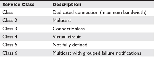
Table 3-1 FC Service Classes
Class 1 service establishes a dedicated connection between host and storage device ports known as node ports or N-ports so that they will have use of the maximum bandwidth until the connection is terminated. N-ports that want to use the class 1 service will request it and, if accepted by the fabric, will have their data transmitted in the order it was received without flow control or error recovery taking place. This allows the ports to achieve maximum bandwidth, but higher-layer protocols will need to conduct error recovery to ensure reliable communication. Using a class 1 service will degrade the performance for other devices if they contend with the class 1 traffic.
Class 2 is a multicast service that delivers frames to multiple N-ports from a single source N-port. Multicast traffic requires fewer frames to be sent on the wire to send identical data to many devices. Without multicasting, a node would need to construct separate frames for each N-port it is communicating with, so if it was communicating with 100 nodes, 100 frames would be sent on the link for the first frame, severely limiting the speed at which the device could transmit to each node. Multicasting takes one frame sent on the link and retransmits it to the other ports. This does not result in saturation on a switched fabric because each port has its own dedicated connection. Furthermore, if multiple ports on another FC switch are to receive the traffic, only one frame is sent over the interswitch link (ISL), and then the receiving FC switch replicates the frame on each destination multicast port that it supports. The fabric does not automatically redeliver failed frames, but it does notify the source of any transmission failures, and it is the responsibility of the multicast source to retransmit failed frames. N-ports can be members of multiple multicast groups, and being a member of a multicast group does not inhibit an N-port from receiving nonmulticast traffic as well.
Class 3 is a connectionless service that transmits frames without delivery confirmation. This results in faster speed, but higher-level protocols are required to ensure reliable delivery.
Class 4 establishes a virtual circuit (VC) between two N-ports. The virtual circuit has a negotiated quality of service (QoS) and a dedicated portion of the N-port’s full bandwidth. This is different from class 1 where the circuit receives the entire N-port bandwidth; 254 simultaneous circuits can be created on a single N-port.
Class 5 is neither fully defined nor implemented. Class 6 is another multicast service, but it differs from class 2 in that one signed frame notifies the sending devices of a failed frame instead of each device sending a failed frame message.
Addressing
Along with a WWPN, FC ports are given a dynamic address when they log into the fabric. This FC address is 24 bits long, and it is divided into three equal 8-bit parts, as shown in Figure 3-1.

Figure 3-1 FC address
The first part is the domain ID. A principal FC switch exists in each fabric. This FC switch is the one that has the lowest switch ID number and priority number configured by the administrator. This allows for a principal FC switch to be configured automatically or set manually if a priority value is assigned. The principal FC switch assigns a unique domain ID to each FC switch to identify it within the fabric. Of the 256 combinations available to an 8-bit domain ID, 239 are usable as domain IDs and 17 are reserved for fabric services that are used to maintain the operation of the fabric. Table 3-2 shows some of the fabric service IDs. The second part of the FC address is the area ID, which is used to represent a set of switch ports such as those that exist on a single blade in an FC director or those in a module on a modular FC switch. The last part of the FC address is the port ID, and this portion of the address uniquely identifies the port.

Table 3-2 Fabric Service IDs
 NOTE A fabric can have a maximum of 15 million devices. This limitation is based on the maximum number of FC addresses that can exist. If you take the 239 domains and multiply them by the 256 possible areas and 256 possible ports in each area, you get 15,663,104. As you can imagine, having this many devices on a fabric would require that each area have the maximum number of ports and that each FC switch have the maximum number of areas.
The multicast server (FFFFF5) directs traffic to a group of N-ports known as a multicast group. Multicast traffic is a more efficient way to send the same data to many devices because fewer frames must be sent on the wire. Each N-port in the multicast group receives the same frames.
The alias server (FFFFF8) registers and unregisters aliases used for creating hunt and multicast groups. Hunt groups represent the group of ports associated with a single node, and multicast groups are the groups of ports designated to receive identical traffic. Each of these hunt or multicast groups receives an alias ID so that it can be uniquely identified on the fabric. Some traffic needs to be sent to all nodes. The broadcast address (FFFFFF) sends a transmission to all N-ports and NL-ports attached to the FC hub or switch.
The clock synchronization server (FFFFF6) keeps clocks consistent among devices by using a 48-bit reference clock. Periodically, the servers will check into the clock synchronization server by sending a clock synchronization request (CSR). The period between synchronization is a value between 1 microsecond and 60 seconds that is set by the clock synchronization server. The default value is every second. The clock synchronization server will respond to CSRs with a clock synchronization update (CSU) command containing its current clock value. Nodes then reset their clock to match the clock value in the CSU. Similarly, the time server (FFFFFB) time stamps messages and synchronizes communication between devices on the fabric.
The security key distribution server (FFFFF7) assigns and manages security keys used for encrypted traffic. This server knows the keys of nodes and, when requested, can send a secret key used for secure communication to the two ports that will be communicating. The secret key is encrypted separately for each port using the port’s distribution key so that only that port can read the secret key. Other ports may require a specific level of service. The QoS server (FFFFF9) manages the quality of service to ensure minimum bandwidth and guaranteed end-to-end delay for virtual channels.
The management server (FFFFFA) distributes network management information. FC uses Simple Network Management Protocol (SNMP) for collecting information on FC devices, and the management server can monitor or modify the management information base (MIB) data. See Chapter 6 for more information on SNMP. Other data is recorded by the fabric controller. The fabric controller (FFFFFD) tracks state changes in attached node ports and distributes the changes to other fabric devices using registered state change notifications (RSCNs).
The name server (FFFFFC) registers names and manages node ports. Devices register their WWN with a name server when they connect to an FC switch in a fabric. Registered devices can query the name server to locate other devices on the fabric by WWN. The name server also maintains a table of WWN-to-FC address mappings.
The logon server (FFFFFE) processes logon requests. It provides details of the N-port to the name server and communicates back to the port to tell it that it has successfully logged into the fabric. The logon server assigns an N-port ID and tracks the association of the node to its N-port IDs.
Link
A link is the physical cabling between two ports. The link is bidirectional in the point-to-point and fabric topologies, consisting of one input and one output cable, discussed later in this chapter, whereas the link in the physical ring arbitrated loop topology is unidirectional with data traveling in one direction from node to node in the ring. Bidirectional links will use cables that have the connections crossed so that each output channel is connected to the input channel on the other end.
Connection
Whereas a link is physical, a connection is logical. A connection is established for communication between two nodes on the FC network. A connection relies upon physical links on the network, but it is at a higher level conceptually because it relies upon the logic of the protocol to establish the connection, including negotiating speeds, finding addresses of communicating parties, and forwarding frames to their destination.
Protocols
Protocols are established ways of communicating, and FC, like its networking counterparts, has several protocols that outline how to send and receive data over an FC network. Each of these protocols transports SCSI commands over a SAN. FC has low overhead and can typically achieve 90 percent of its rated capacity of 2, 4, 8, or 16 Gbps. Four FC protocols can be used to connect FC devices in a SAN. The first, Fibre Channel Protocol (FCP), uses FC specifications for the entire protocol stack, but others, including Fibre Channel over IP (FCIP), Internet Fibre Channel Protocol (iFCP), and Fibre Channel over Ethernet (FCoE), combine elements of FC with Ethernet.
FCP
Fibre Channel Protocol (FCP) is one of the most popular high-performance storage protocols. FCP is defined with five layers, but only four of the layers are actually implemented in the technology. The layers are depicted in Figure 3-2.

Figure 3-2 FC layers 0 through 4
The FC layers can help you understand the process of sending or receiving data. A device works from the top layer to the bottom layer when sending data. The bottom layer, FC-0, places the data on the physical media, and the receiving end then processes the data from the bottom layer up so that the same data sent is received.
FC-4 is the upper-layer protocol mapping. It is responsible for encapsulating upper-layer protocols, including Small Computer System Interface (SCSI), Intelligent Peripheral Interface (IPI), High Performance Parallel Interface (HIPPI), Asynchronous Transfer Mode (ATM), and Single Byte Command Code Set Mapping (SBCCS), on top of FC. FC-4 encompasses the fabric logon (FLOGI) and port logon (PLOGI) procedures, state notifications, and name services.
Physical vs. Logical Connections
Physical connections differ from logical connections. The physical connection consists of the hardware components such as ports, cards, cables, and switches that form the connection between the source and destination. The logical connection is the establishment of communication between the source and destination. A physical connection provides the potential for a logical connection, just as a water pipe would provide a physical connection, but when water flows out of your faucet, it is like a logical connection that utilizes the physical link. (This example is not perfect since water is a physical thing you can touch or feel, but it should make the concept a bit more tangible.)
The terms physical and logical are used often in computer books, including this one. Physical is related to something you can feel and touch. Often, this is a piece of computer hardware such as a cable, network interface card, host bus adapter, or hard disk drive. Logical exists on top of physical components, and it is how a component or concept is interfaced with in software.
FC-3 is known as the services layer, and it is designed to support striping, hunt groups, and spanning of multiple ports. Striping is a method where multiple N-ports are used to concurrently transmit data. The data is split into pieces much like striping on a disk, and each piece is sent through a different N-port. Hunt groups allow multiple ports to use the same alias address.
FC-2 breaks the data into smaller chunks called frames and performs flow control to ensure that devices receive data at a speed they can support. FC-2 is divided into three sublayers called exchange, sequence, and frame. The exchange sublayer defines a communication flow between partners that has been established but not yet terminated. For example, an exchange would be created when a host maps a file system on a remote logical unit. The partners include an Exchange Originator, which is the node that started the communication, and the Exchange Responder, which is the node that answered the originator’s request. The exchanges are identified by the IDs of the originator (OX_ ID) and the responder (RX_ID). The OX_ID is generated dynamically when the first frame in the exchange is sent to the responder, and the RX_ID is generated when the responder answers the first frame. Two nodes can have multiple exchanges as long as the OX_ID and RX_ID are unique.
Exchanges do not need to have data flowing through them since they can be active or passive. Active exchanges have current I/O associated with them, and passive exchanges are simply open without current I/O.
The sequence sublayer divides an exchange into smaller segments that can comprise such things as a single file or a database transaction. Sequences contain the data traveling in only one direction, from the originator to the receiver or from the receiver to the originator. A single file transfer within an exchange might have four or more sequences. The first sequence is the request for the file from the originator to the responder. This would be followed by another sequence acknowledging receipt for the request from the responder to the originator. Another sequence from the responder to the originator would contain the file, and then a last sequence from the originator to the responder would confirm the receipt of the file. All of these sequences would be contained in a single exchange. A sequence ID (SEQ_ID) is placed in each frame in the sequence, and a sequence count (SEQ_CNT) identifies individual frames within the sequence. This brings us to the third sublayer, frames.
The frame sublayer is responsible for packaging data or control information into smaller pieces called frames. Data frames contain a portion of the data, also known as a payload. Control frames contain instructions or responses such as acknowledgements (ACKs) of frame receipt, link response frames indicating that the node is too busy to receive data or that it has rejected data, and changes to the way frames are processed called link command frames. Figure 3-3 shows an exchange for reading a file.

Figure 3-3 FC read file exchange
FC-1 encodes the data so that it can be transmitted efficiently on the link. It uses the 8b/10b encoding method, which represents 8 bits of data as 10 bits of data. The encoding scheme ensures that a signal change from a set of 0s to a set of 1s occurs at least every 5 bits to ensure that the sending and receiving devices are synchronized; 8b/10b also has a uniform distribution of 1s and 0s that allows for lower direct currents to be used in the physical layer (FC-0).
FC-0 is responsible for the physical transmission of electrical or light impulses across a wire depending on whether copper or fiber-optic media is used. Data is sent serially to achieve high transfer rates. Distances and speeds are governed by the hardware utilized at this layer, with fiber-optic cables achieving higher speeds and distances than copper. The different types of fiber and copper cables are discussed in Chapter 4.
FCIP
Fibre Channel over IP (FCIP) is a protocol that sends FC protocol data over an IP network. FCIP is implemented with two or more FCIP-equipped switches that have connections to both the FCP and TCP/IP networks. The TCP/IP connection imitates the port used to connect two FC switches, known as an E-port or expansion port. FCIP calls this port a virtual E-port. To the FCP network, the virtual E-port can be used like any other ISL. Similar to physical E-ports, virtual E-ports are connected to a single destination, but multiple virtual E-ports can be port channeled for increased reliability and speed. Multiple virtual E-ports must be used to link multiple destination networks. FCP frames are sent to the virtual E-port that packages them inside TCP/IP packets in a process known as encapsulation. These packets traverse the LAN or WAN like any other TCP/IP packets. At a destination FCIP switch, the FCP frames are extracted from the TCP/IP packets and then dropped onto the destination FCP network.
 EXAM TIP FCIP is primarily used to connect remote FC SANs together over an IP wide area network.
The beauty of FCIP is that, besides the FCIP-enabled switches, other SAN devices do not need to have knowledge of FCIP to communicate with the rest of the fabric even though the fabric is separated. FCP devices see it as one big fabric, with the entire connection between SANs appearing as a single ISL even though this connection may traverse many routers and links in the process. FCIP also supports encrypting traffic using IP Security (IPSec). Figure 3-4 shows a host and storage device connected to FC networks that are joined together over an IP network using FCIP. Note how the link between the two FCIP-capable switches would appear as one link to the FC network when it actually traverses eight links consisting of seven IP devices and two FCIP-capable switches.

Figure 3-4 FC traffic tunneled over IP with FCIP
iFCP
Internet Fibre Channel Protocol (iFCP) was originally designed to translate FCP traffic from end nodes onto a TCP/IP network and to use the TCP/IP network for the transmission of all storage traffic. However, iFCP equipment and FCP HBAs are more expensive than IP NICs, so iSCSI has been favored over iFCP. Figure 3-5 depicts an iFCP network. iFCP has seen practical implementation as a gateway similar to FCIP. It supports IPSec encryption for increased security, and multiple iFCP links can be grouped together to increase the bandwidth available for interswitch communication in what is known as a port channel.

Figure 3-5 iFCP network
FCoE
The Fibre Channel over Ethernet (FCoE) protocol uses the FC-4 upper-layer protocol mapping and FC-3 services layer, but Ethernet performs the FC-2 and FC-1 functions through the Data Link LLC sublayer and Data Link MAC sublayers. FCoE runs on Category 5 cabling instead of optical cabling like FCP does. FCoE is not routable, so it is suitable only on networks where the storage and hosts are on the same VLAN or network segment. FCoE is different from FCIP in that it does not use TCP/IP. Figure 3-6 compares the layers of FCP, FCIP, iFCP, FCoE, and iSCSI.
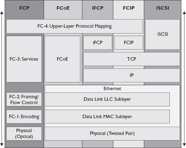
Figure 3-6 Comparing storage networking protocol layers
An FCoE Forwarder (FCF) is a device that has the necessary services and ports to operate as an FCoE switch. FCFs have an FCoE controller and MAC address for one FCoE port or multiple ports if FCoE bridging is used. FCFs also support FCoE VLANs. The FCoE controller creates virtual ports for FCoE VLANS using the FCoE Initialization Protocol (FIP).
Topologies
Three FC topologies define how FC devices are connected to one another. FC point-to-point is used to directly connect two devices, while FC arbitrated loop and FC switched fabric are used to connect many devices together.
Point-to-Point
The FC point-to-point (FC-P2P) topology is a connection between two devices, and it is primarily used with DAS systems as an alternative to SCSI. FC-P2P can connect two devices over a distance of 10,000 meters (10 km), whereas SCSI is limited to 25 meters. Figure 3-7 depicts a host and a storage array in an FC-P2P topology.

Figure 3-7 FC-P2P topology
Arbitrated Loop
The FC arbitrated loop (FC-AL) topology connects multiple devices together using a ring. This means each device is connected to another device forming a chain that eventually connects back to form an unbroken circle. Each device in the loop is connected to two neighbors, and communication flows in only one direction, so one link is always the sender and one is the receiver. Only one sender and one receiver may communicate on the FC-AL at a time, so this is considered a shared medium. Resource contention increases as more devices are added to the FC-AL network, and you should expect performance to drop as well. FC-AL addresses do not contain the domain ID and area ID. Instead, they contain only an 8-bit number. This would give FC-AL 256 possible addresses, but FC-AL only uses numbers that contain an even number of 1s and 0s, leaving 127 with one reserved for a switch. In the end, FC-AL is limited to 126 devices. However, the number of addresses is not really the main limiting factor since an implementation approaching 126 nodes would be far from ideal given the performance loss each new node creates. Figure 3-8 depicts several hosts and storage arrays in an FC-AL topology configured as a physical ring.
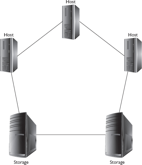
Figure 3-8 Physical ring FC-AL topology
A physical ring topology is difficult to manage because each link between two nodes on the FC-AL network is a potential point of failure. Network connectivity for all nodes can be interrupted by a single cable failure. For this reason, FC-AL is commonly implemented using hubs. Each node on the network is cabled to a port on one or more hubs. The hubs create a loop between the ports in the switch and links between switches while bypassing ports that are not in use or in a failed state. Another description for this is physical star, logical ring. The physical cabling looks like a star with a central device and many other devices connected to it, but data flows logically like a ring with each device passing the data to the next one in the chain until it reaches its destination. Figure 3-9 depicts several hosts and storage arrays in an FC-AL topology configured as a physical star.

Figure 3-9 Physical star FC-AL topology
FC-AL is rarely used to connect hosts and storage devices, but you may encounter it within a storage array where few back-end ports are available to connect several disk enclosures or in situations where a guaranteed maximum response time is necessary for all components.
Switched Fabric
The FC fabric, also known as FC switched fabric (FC-SW), is by far the most common FC topology and the one you will want to be most familiar with. The term fabric is used to describe a network topology where components pass data to each other through interconnecting switches. The word fabric is used as a metaphor to illustrate the idea that network components and their relationships form lines that weave back and forth resembling a piece of cloth.
In a switched fabric, storage devices and hosts are connected to one another using switches. Switches are similar to hubs in that they are a physical star. Devices are connected to ports on the switches that enable communication between devices. However, FC-SW differs from FC-AL using hubs in that communication between ports is isolated from other ports. The medium is not shared among the devices, so each communication between the sender and the receiver can use the maximum available bandwidth when connecting over the same switch. FC-SW fabrics scale out by adding more switches connected together using ISLs, and thus connections that cross over ISLs will share the ISL with other communication crossing that ISL. Figure 3-10 depicts several hosts and storage arrays in an FC-SW topology.
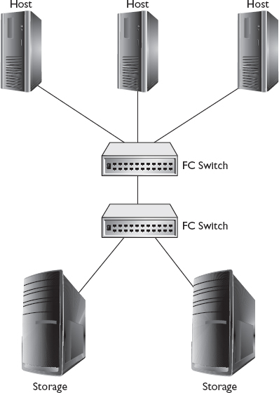
Figure 3-10 FC-SW topology
The FC-SW topology supports millions of devices as compared to FC-AL’s 126 devices. The scope of a fabric can be defined by the number of tiers it contains, which is determined by the number of ISLs between the two furthest points on the fabric. Tiers are important because they impact the amount of time it takes to complete fabric reconfiguration. Reconfiguration happens when devices are added to or removed from the fabric. FC uses registered state change notifications to inform FC devices of additions and removals. N-ports and NL-ports can register to receive state change notifications, but they are not required to do so.
Redundant Fabric
A redundant fabric is one that has separate interconnecting devices such as switches and directors but the same end nodes. The redundant fabric is used to prevent a loss in communication because of fabric reconfiguration or a loss of an entire fabric.
NOTE Topologies that are fully redundant, meaning that every node is connected to every other node, are known as a mesh.ISL
The interswitch link is used to connect two FC switches in an FC fabric. The ports comprising the ISL need to be E-ports, a specific port designed for communication between FC switches. Communication crossing the ISL will contend for available bandwidth, so ISLs can be a primary limiting factor in FC SAN performance. You can achieve the best performance by reducing the number of ISLs that need to be crossed.
Port Channel
Multiple ISLs between FC switches can be grouped together into a port channel to increase the bandwidth available for interswitch communication. Traffic traversing the port channel is distributed among the ISLs to take advantage of the bandwidth of each ISL concurrently. Port channeling can greatly increase the performance of traffic traversing multiple FC switches at the cost of using more ports on each switch. Figure 3-11 shows four ISLs that have been combined into one port channel. The number of ISLs in a port channel should be determined by the sum of the bandwidth required by hosts that need to connect to a storage device on another FC switch. In some cases, it may be advantageous to set a bandwidth threshold on the port channel so that it does not consume more than a ceiling limit. This is typically used to reserve bandwidth so that application performance stays the same when one or more ISLs in the port channel go offline. It may be more advantageous to upgrade the FC switch to a larger capacity device if it is determined that many ISL links will be necessary to support SAN traffic patterns. Another option would be to move some hosts to the same switch as storage devices or to a switch with a larger port channel to conserve FC ports. The remaining hosts would connect to switches with smaller port channels or even a single ISL.
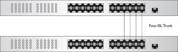
Figure 3-11 Port channel created with four ISLs
EXAM TIP Port channels must be created between a single pair of devices, and each ISL in the port channel must run at the same speed.Trunking
Trunking is used with virtual SANs (VSANs). VSANs are a subset of ports in an FC fabric that are segmented from the rest of the fabric. This is typically performed for security reasons or to reduce overall traffic on the SAN through VSAN partitioning. Trunking allows data from multiple VSANs to traverse the same ISL. Trunks may be used with port channels to provide redundancy in case a single ISL fails and to better aggregate bandwidth. If a single VSAN needs a lot of bandwidth, it can utilize multiple ISLs, but at other times it may not need that much bandwidth, so the bandwidth will be available to other VSANs. This is an improvement over mapping a single VSAN to an ISL because it offers better utilization of ISL.
Port Types
FC ports have different uses that are described by one or more letters. They are compared in Table 3-3, and each is described in more detail in the following sections.
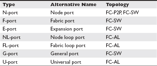
Table 3-3 FC Port Types
N-port
N-ports, or “node” ports, are used on end devices such as a server, workstation, or tape disk or storage array in an FC network. If the network is a tree, the end devices would be the leaves on the tree, and in fact, sometimes end devices are referred to as leaves. These devices include hosts such as servers or workstations and storage devices such as storage arrays, tape drives, or network attached storage. N-ports are given an ID called the N-port ID by the fabric logon server when the port first becomes active on the fabric. N-ports are initialized in three steps. First, the N-port sends a fabric logon request called an FLOGI to the login server (address FFFFFE) to obtain a valid address. It then registers the address with the name server by sending a port logon request called a PLOGI to the name server (address FFFFFC). Finally, the N-port sends a state change registration (SCR) to the fabric controller (address FFFFFD) to register the state change notification.
F-port
F-ports, or “fabric” ports, reside on an FC switch, and they connect to N-ports. F-ports can receive frames from N-ports so that the frames can be switched to their destination, and they deliver frames addressed to the N-port ID they are connected to.
E-port
E-ports, or “expansion” ports, are used to create a connection between two switches known as an ISL. E-ports connect to other E-ports. When data is received on an F-port for a node on a different switch, the frame is sent over one or more ISLs to the switch that has the destination N-port ID. Figure 3-12 shows the location of N-ports, F-ports, and E-ports in an FC-SW topology.
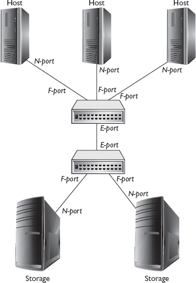
Figure 3-12 N-ports, F-ports, and E-ports in FC-SW topology
NL-port
NL-ports, or “node loop” ports, are used to connect nodes that are members of an FC-AL ring. Figure 3-13 shows the location of NL-ports in an FC-AL topology.
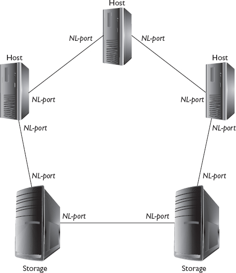
Figure 3-13 NL-ports in FC-AL topology
FL-port
FL-ports, or “fabric loop” ports, are used to connect to NL ports when hubs are used in the FC-AL physical star, logical ring implementation. Figure 3-14 shows the location of NL-ports and FL-ports when using a hub in a physical star implementation of the FC-AL topology.

Figure 3-14 NL-ports and FL-ports in FC-AL physical star topology
G-port
G-ports, or “generic” ports, can function as either an F-port or an E-port in FC-SW topologies. Many modern switches are equipped with G-ports that can detect whether they are connected to a node or a switch and configure themselves automatically as an F-port to connect to nodes or an E-port to connect to another switch.
U-port
U-ports, or “universal” ports, are like generic ports in that they can function as either an NL-port or an FL-port. U-ports are used in the FC-AL topology.
Tools
Several tools such as port error counters, fcping, name servers, and rescans can help in managing, maintaining, and troubleshooting an FC network.
Port Error Counters
Port error counters are useful for identifying problems with FC switches, host bus adapters (HBAs), or cables and for diagnosing congestion or connectivity problems. Error counters can be viewed on devices with FC ports, but each vendor can choose to implement the counters they deem suitable for their device. More counters may be available for some equipment such as switches than for other equipment like HBAs. Counters for HBAs in storage arrays may have more counters available than those installed in a host, and those counters are typically accessed via a storage array management utility or via a command-line connection to the array such as Secure Shell (SSH). Port error counters on switches can be viewed from the switch management utility or command line. Additionally, counters may be sent to a central collection device using protocols such as Simple Network Management Protocol (SNMP). Some counters that may be available for your device are as follows:
• Bad frames Some frames are received without an end of frame (EOF) or with one that is unreadable. This can be caused by a loss of synchronization on the link. Switches will add an EOF normal invalid or abort to the end of the frame, causing the destination address to drop the frame.
• Decode errors FC uses the 8b/10b encoding scheme, which is organized into words made up of 8 bytes represented at 10 bits each. As discussed earlier, 8b/10b initiates a signal change from a set of 0s to a set of 1s at least every 5 bits, and the number of 0s and 1s is uniform. Words that do not have a signal change at least every 5 bits, or words that do not have uniform 0s and 1s, are invalid and result in a decode error. A high number of decode errors could point to a faulty cable or port.
• Fabric busy Fabric busy events are generated when the FC fabric sends out notifications that higher-priority class traffic is using the link.
• Invalid CRC The cyclic redundancy check (CRC) is a mathematical value that is computed based on the contents of the frame. It is compared when frames are received to determine whether the contents changed in transit. If the CRC differs, it is termed invalid, and this counter increases.
• Invalid destination address This error occurs when an incorrect source ID or destination ID is included in a frame. Invalid source addresses are used in spoofing attacks, and invalid destination IDs are used in denial-of-service attacks.
• Short frames Short frames are those that are less than the minimum frame size of 24 bytes.
fcping
The fcping command is used to issue an FC Extended Link Service (ELS) request to a port or pair of ports. Ports that receive an ELS request will respond, letting the user know that it is active and able to communicate. If a device fails to respond to fcping, it may be unavailable. This could be the result of a port or cable failure, software failure, or an administrator taking the port offline. Some devices may be configured to not respond to ELS messages, so it is important to not assume that the device is unavailable just from the result of fcping. Check the port status lights as well. You can do this by physically looking at the FC switch or HBA or by viewing the port status in a switch’s command-line or web administrative console.
Running the fcping command from an FC switch to WWN 21:01:00:E0:8B:A5:26:6A would produce the following output:

The first line shows the prompt storageplusswitch:admin>, which indicates that you are logged onto a switch called storageplusswitch under the username admin. The fcping command follows the prompt. The first line after the command confirms you are fcpinging WWN 21:01:00:E0:8B:A5:26:6A, which has an FC-ID of fd1091. Each ELS reply is then given along with the time it took to receive a reply. The last line of the output shows the statistics beginning with the shortest (min), average (avg), and longest (max) ELS reply in the set. The output of this command shows that all five out of five pings were sent, and ELS replies were received for each of the five, with the shortest response taking 902 microseconds, the average 1,070, and the longest 1,222.
This example is given for a basic command, but fcping can include other variables as well. The syntax for the command may be implemented differently by different switch vendors or software packages, so this book will cover options but not the exact syntax. Some fcping options include specifying the number of ELS messages to send, the interval in milliseconds between ELS messages, or the ELS message size. WWN may also be substituted for the FC-ID.
Name Server
Name servers are important to the operation of an FC fabric because they map the WWN and FC port addresses. Name servers can be queried to find the WWN and port for a node on the FC network, which can be useful when troubleshooting FC network issues. Nodes are referenced by WWN often in software, but it may be necessary to view port error counters for that WWN to isolate connectivity or performance issues by querying the name server. Connectivity problems can arise if the name server does not have information on a WWN, so the name server can be used to verify that an entry exists for the troubled node.
Rescan
Hosts connected to a SAN may have storage allocated to them by storage arrays on the SAN. The provisioning process is discussed in Chapter 6. In some cases, the storage may not immediately be seen by the host, and other times storage that has been available might not be visible in the operating system. A rescan will search for storage so that it can be used on the host.
There are four steps for performing a rescan in Linux. You will need to know which HBA is connected to the SAN that contains the storage, and then you can determine the host number for that HBA by issuing the following command:
The result of this command will be the word host followed by a number that you will use in the next steps. The second step is to send a Loop Initialization Protocol (LIP) rescan on the FC bus using the following command:
The host will scan the bus looking for storage and update the system’s SCSI layer with any new or removed devices. This may cause delays or timeouts in I/O operations, so use care when issuing the command. The command takes time to complete, and you may be presented with a command prompt before the scan has fully completed. Give the command 15 to 20 seconds before issuing other commands just to be safe. Use the host number obtained in the previous step in place of the word host in the command.
Next, perform a rescan on the HBA with this command and add any new devices found; it will not remove any devices:
Finally, check to see whether the storage is available with this command:
NOTE Linux commands may vary based on distribution and version.Microsoft Windows manages storage within the Server Manager console. Open Server Manager by clicking Start, right-clicking Computer, and selecting Manage. Expand the storage container. Right-click Disk Management, as depicted in Figure 3-15, and select Rescan Disks. New storage will appear in the bottom pane.

Figure 3-15 Disk Management within Server Manager
iSCSI Storage Network
Internet Small Computer System Interface (iSCSI) is a protocol that sends SCSI disk commands over an IP network. iSCSI as a storage networking technology offers cost-conscious companies an excellent solution at a much lower cost than FC. iSCSI is most commonly deployed over Gigabit Ethernet, utilizing Category 5 (Cat5) cabling, Gigabit Ethernet switches, and network interface cards (NICs) such as those used in computer networks.
Block Mode
Block mode is a method for accessing storage that is used by disk drivers such as SCSI. Block mode requires few operations to access disks as compared with protocols such as FTP or CIFS/SMB.
Initiator
An iSCSI initiator is a device that creates a session by sending commands to a target. Hosts that connect to an iSCSI network require an initiator to connect to iSCSI logical unit numbers (LUNs). Software initiators are implemented as part of an operating system such as Microsoft Windows or Linux. Hardware initiators, on the other hand, are built into iSCSI host bus adapters, and they do not rely upon the OS to structure and process iSCSI commands. This can reduce some of the load on the host system. Hardware initiators are not an option when using NICs, so this is something that will need to be considered when deciding whether to utilize NICs or iSCSI HBAs.
Target
iSCSI targets await commands from iSCSI initiators. LUNs are located on targets, and initiators interface with the LUNs by sending commands to the target. iSCSI storage arrays are equipped with software or hardware that manages targets, but there is software available for servers and workstations that allows local drives and folders to be allocated to other devices on the network as an iSCSI target.
Initiators must map targets in order to start using their storage. Targets can be located manually by IP address and port. By default, iSCSI uses TCP ports 860 and 3260. Manual target mapping may be fine for small, simple environments, but it becomes necessary to use a method of target discovery in larger and more complex environments where there may be many targets and initiators.
Service Location Protocol
The Service Location Protocol (SLP) and Internet Storage Name Server (iSNS) both provide a method for initiators to discover storage targets. These systems utilize a server that provides name-to-address resolution. SLP is a simple-to-implement client-server protocol that consists of user agents, service agents, and discovery agents. Discovery agents retain a list of targets and their resources, and they make this list available to user agents that reside on initiators. Service agents reside on targets, and they register their resources with the discovery agent or advertise their resources if a discovery agent is not present. Security is maintained through a list of initiators that are authorized to connect to a target. This list is known as a scope entry. SLP resources are referenced by a service universal resource locator (URL) made up of the target IP address, port, and friendly name. For example, the resource named MainDatabaseLogs on IP address 192.168.5.56 using port 3260 would have the following service URL: 192.168.5.56:3260/MainDatabaseLogs. SLP is suitable for small iSCSI networks, but it does not scale well with larger implementations because of the large amount of administrative data such as logon requests that must traverse the iSCSI network.
Internet Storage Name Server
iSNS allows for initiators to discover iSCSI targets. iSNS can retain target information for both iSCSI- and FC-attached devices over iFCP gateways in iSNS databases. iSNS databases can reside on iSCSI switches or on software-based iSNS databases such as those bundled in Linux, Solaris, and Microsoft Windows servers. iSNS databases can be distributed among many iSCSI switches to allow for larger scalability. iSNS servers on targets register their resources and state changes with SNS databases, which initiators running iSNS clients can query to find available targets.
EXAM TIP iSNS is the predominant method for iSCSI target discovery.iSNS URLs begin with iscsi:// followed by the target name, port, resource name, and then an optional WWPN that is used when connecting to FC resources. The following URL would be used to connect to an iSCSI resource called Logs on the MainDatabase.Test.com device using port 3260: iscsi://MainDatabase.Test.com:3260/Logs. If the resource was on iFCP, the URL would be structured as follows: iscsi://MainDatabase.Test.com/Logs?WWPN=F3EB56A914.
iSNS improves on SLP by adding state change notification alerts that inform initiators of target availability. iSNS databases automatically remove entries after a period of inactivity so that stale records do not remain in the database. Targets must periodically update the iSNS database to ensure that their resources are not removed because of inactivity. Security and scalability are provided through discovery domains (DDs). DDs contain targets and imitators that are allowed to connect to one another. Initiators can belong to many DDs so that they can connect to multiple resources. Initiators and targets do not belong to any zones by default, so new initiators are prevented from connecting to resources, and newly provisioned targets are prevented from being accessed until they are placed into a zone. DDs also restrict target discovery information that flows through the iSCSI network to a smaller set of initiators and targets, which allows the iSNS protocol to scale better in larger environments.
Ethernet Switching
Traffic traverses an iSCSI network via Ethernet switches. Companies can use existing Ethernet switches for iSCSI traffic if they want and avoid the cost of purchasing additional Ethernet switches. This also decreases the management cost of the SAN because another technology (and its management interfaces) does not need to be introduced into the network.
It is common to use a virtual local area network (VLAN) to separate iSCSI traffic on Ethernet switches from computer network traffic. VLANs are created by assigning a VLAN ID to each Ethernet switch that will contain ports in the VLAN. Each port is then associated with the VLAN ID. These ports will not be able to communicate with ports that have a different VLAN ID unless a router is used to route between the VLANs. iSCSI traffic can be isolated from the rest of the network with VLANs, which protects iSCSI traffic from being observed by other hosts on the network and isolates the iSCSI network cards from broadcast traffic originating from the computer network. Ports used to connect Ethernet switches together need to be configured as port channel ports in order to send VLAN traffic to another Ethernet switch. These port channel ports tag the traffic with a VLAN ID so that the receiving Ethernet switch will know which VLAN to place the traffic on when it arrives.
Jumbo Frame
Storage administrators can modify port settings on an Ethernet switch to improve the speed of iSCSI operations. Jumbo frames can boost the performance of the iSCSI network. Jumbo frames are Ethernet frames that are larger than 1,500 bytes. Jumbo frames can be as large as 9,000 bytes. Ethernet frames consist of header information and data. Headers include such things as source and destination MAC addresses, protocol information, and flags for supported settings. An Ethernet frame header consists of 38 bytes and is depicted in Figure 3-16.

Figure 3-16 Ethernet frame
It would take 14 standard Ethernet frames to transfer a 20,000-byte file incurring 532 bytes of overhead, but it would take only three jumbo frames to transfer the same file incurring only 114 bytes of overhead. In this example, overhead was reduced by almost 80 percent, but the overhead consisted of only 3 percent of the total data transferred, so the total frame size savings are still rather small overall. However, each frame results in processing that must occur on the sending, receiving, and intermediary units, so a reduction in the number of frames will also reduce the amount of processing required to segment, forward, and reassemble frames. Figure 3-17 shows a jumbo frame. Jumbo frames must be supported on Ethernet switches and NICs or HBAs that are connected to the Ethernet switches in order for a connection to be maintained.
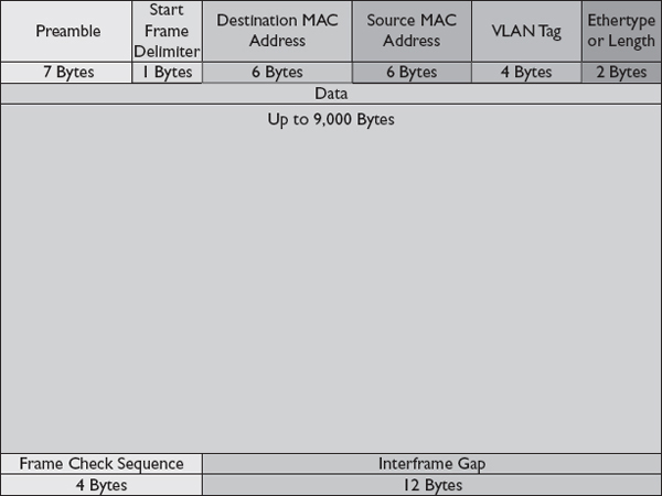
Figure 3-17 Ethernet jumbo frame
Baby-Jumbo Frame
Baby-jumbo frames, also called baby giants, are frames between 1,500 and 9,500 bytes. They are used for services such as the Layer 2 Tunneling Protocol (L2TP), virtual private network (VPN), Multiprotocol Label Switching (MPLS), and Tagged Quality of Service (QoS) frames.
Ethernet Features
Since iSCSI is based on Ethernet, it is good to understand how Ethernet works as a networking technology and how the local area network (LAN), metropolitan area network (MAN), and wide area network (WAN) function. iSCSI can operate over a LAN, MAN, or WAN depending on the organization’s requirements. Ethernet devices are classified based on the speed they support. For example, Ethernet runs at 10 Mbps, while 100-Mbps Ethernet networks are known as Fast Ethernet. Gigabit Ethernet runs at 1,000 Mbps and is most commonly seen today. All flavors of Ethernet have higher overhead than Fibre Channel. Ethernet can typically achieve 50 to 85 percent of its rated capacity of 10 Mbps, 100 Mbps, 1 Gbps, or 10 Gbps, while FC can consistently achieve 90 percent of its rated capacity of 2, 4, 8, or 16 Gbps.
LAN
LANs connect computers in a single site. LANs are used for file sharing, printer sharing, running applications from servers, and many more activities that may be taken for granted at a typical organization. Before LANs, data had to be transported using a disk, such as a floppy disk, to another machine in order to be shared, and printers were often connected to each machine that needed to print on a regular basis, or users transported documents to a device that could print. The same was true for scanners.
MAN
A MAN is a larger network than a WAN. MANs extend to two or more sites within a metropolitan area such as a city or county. For example, large hospitals or universities have MANs that connect their various buildings together so that applications, file servers, and network resources such as domain controllers or DHCP servers do not need to be housed and supported in each building. Each building has its own LAN, and all the buildings together form a MAN. The LAN at each location will typically contain Ethernet switches that connect the various devices together and then a high-bandwidth link to other buildings. The MAN may be hierarchical where buildings connect to a central building that houses shared resources, or they may be configured as a mesh where many buildings connect to one another so that if one link fails, multiple other redundant paths connect the buildings. Some buildings may be in different areas of the city, but they are still part of the same MAN.
WAN
A WAN is a network that connects geographically distant locations. The Internet is the most common WAN because it connects people from around the world. Organizations will set up WAN links to connect remote offices so that the resources in one office, such as file servers, applications, or storage, can be shared with other locations.
Class of Service
Class of service (CoS) is a way of prioritizing types of traffic. It is specified as part of IEEE P802.1p. As an Ethernet technology, CoS can be implemented on lower-cost Ethernet switches with CoS support rather than relying on layer 3 switches or slower and more expensive routers to prioritize traffic. CoS operates as the Data Link layer (layer 2) and is contained within Ethernet frames. The 802.1q Ethernet header contains a 3-bit field that can specify one of eight CoS levels ranging from 0 to 7, with 0 being the lowest priority and 7 being the highest. The IEEE has issued guidelines for the use of the CoS levels, but vendors are free to implement the classes as they see fit. Table 3-4 lists the IEEE’s CoS level guidelines.

Table 3-4 CoS Levels According to the IEEE Guidelines (IEEE 802.1Q-2005)
Priority Tagging
Priority tagging is a way of differentiating among types of traffic that should be treated differently, with some being given priority over others. Priority tagging uses an 802.1p tag that takes up 3 bits in the Ethernet header frame.
Data Center Bridging
A data center is a facility with the primary purpose of housing computer information systems, including servers, storage arrays, NAS, DAS, switches, routers, and firewalls. Data centers are usually equipped with features such as high-powered cooling devices, redundant power, backup generators, multiple Internet connections, fire suppression systems, and advanced power and temperature monitoring systems. Data center bridging (DCB), also known as data center Ethernet (DCE) or convergence enhanced Ethernet (CCE), is a set of technologies and specifications by the Institute of Electrical and Electronics Engineers (IEEE) and Internet Engineering Task Force (IETF) intended to improve Ethernet performance and reliability for the data center. DCB is commonly used with FCoE because FC has a lower tolerance for frame loss, but DCB can benefit other storage technologies that operate over Ethernet as well. For example, clustering is improved with DCB by prioritizing cluster control messages above data transfer frames used in clusters. Cluster control messages ensure that the cluster remains operational, so it is more important for them to avoid being dropped because of Ethernet congestion. Each of the technologies that make up DCB is described briefly here:
• IEEE 802.1AB Called Link Layer Discovery Protocol (LLDP), this is a method for obtaining information on the topology used and neighboring devices on an Ethernet LAN or MAN.
• IEEE 802.1aq Called Shortest Path Bridging (SPB), this allows VLANs to share bridging table information that contains the MAC addresses of devices connected to ports. It also specifies 16 other multipath options such as the ability for multiple redundant links connected to core Ethernet switches to be used at the same time. Without 802.1aq, the Spanning Tree Protocol would turn off one of the redundant links to prevent broadcast messages from repeating on the network indefinitely and creating more traffic exponentially in what is known as a broadcast storm, but 802.1aq allows both links to work in parallel to load balance the traffic while still preventing broadcast storms.
• IEEE 802.1Qau Termed Congestion Notification (CN), this allows links to reduce the transmission rate instead of dropping frames.
• IEEE 802.1Qaz Called Enhanced Transmission Selection (ETS), this allows unused bandwidth assigned to classes to be reassigned to other classes until it is needed.
• IEEE 802.1Qbb Also called Priority-based Flow Control (PFC), this is a method of link-level flow control that allows lower classes of service to be paused while higher classes of service are allowed through. Link-level flow control link scheduling allows a certain amount of a link’s bandwidth to be assigned to a class of service, allowing for more predictable performance from Ethernet links.
• IEEE 802.3bd This adds a new type of Ethernet control frame to allow for PFC.
• IETF Transparent Interconnection of Lots of Links (TRILL) This defines a type of Ethernet switch called a Routing Bridge (RBridge) that can compute better paths to forward frames to Ethernet switches. RBridges can do this because they have more information on the devices that are connected to other RBridges. RBridges inform neighboring RBridges of their connections, and those connections are then shared again with neighbors similar to how routers distribute routing information.
10GigE (10GbE)
10 Gigabit Ethernet (10GigE) is the latest version of Ethernet and can run at 10 Gbps (10,000 Mbps). The IEEE standardized it in 802.3ae, and it uses Category 6 or Category 7 cables instead of the Category 5 cables used in Gigabit Ethernet. iSCSI running over 10GigE can achieve speeds relative to FC 8 Gbps links; however, at the time of this book, 10GigE devices are still quite a bit more expensive than Gigabit Ethernet.
Tools
Several tools such as ping, trace route, ipconfig, and nslookup can help in managing, maintaining, and troubleshooting an FC network.
ping
The ping tool is used to verify connectivity to a device on an IP network. Devices are referenced by name or IP address, and the command will send several Internet Control Message Protocol (ICMP) echo request messages (pings) to the node and wait for an ICMP echo reply (pong) in response.
tracert/traceroute
The trace route command displays the path a packet takes through an IP network to reach its destination. Windows devices use the command tracert, and Linux devices use the command traceroute to perform a trace route. The trace route sends messages to a destination with a time to live (TTL) starting at 1 and increasing until it reaches the destination. Each device along the path to the destination will decrease the TTL in the packet. When the TTL reaches 0, the packet is discarded, and an ICMP time exceeded message is sent back to the sender notifying them of the discarded packet. The trace route tool uses these ICMP time exceeded messages to identify each node or hop along the way to the destination.
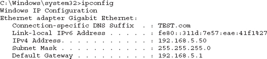
ipconfig/ifconfig
The ipconfig command in Windows and the ifconfig command in Linux displays the TCP/IP configuration for the NICs in the device. Output from an ipconfig command showing the IPv4 and IPv6 addresses, domain name, subnet mask, and default gateway is displayed here:
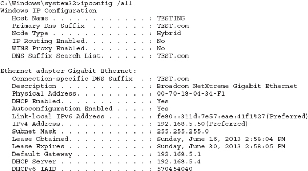
The ipconfig /all command displays much more information than the ipconfig command alone. This information can be useful in troubleshooting or in documenting the network. Some sample output of the ipconfig /all command is given here:

nslookup
The nslookup command can display information on the Domain Name System (DNS) servers that are in use on the network and query the DNS servers for IP address or DNS name mappings. Typing nslookup followed by the name of a computer on the network will display the IP address of that computer. The response will be authoritative if the DNS record for that computer is maintained on the DNS server, as can be seen in the following command that queries the name server for a host called testing.test.com. Nonauthoritative responses are issued when the server is not managing that machine.

ARP
The Address Resolution Protocol (ARP) translates an IP address to a MAC address on Ethernet networks. IP addresses are needed in the OSI layer 3 packet, but this is encapsulated into a layer 2 frame that uses the MAC address for its source and destination. The encapsulated packet may traverse multiple switches before it reaches a router that reads the packet information. Each switch along the way will repackage the packet into a new frame that lists the switch address as the source and the next layer 2 device along the way as the destination. To determine what the MAC address is, these devices will use the ARP protocol.
The ARP command can be used to list the MAC addresses a machine knows about, modify the MAC-address-to-IP-address mappings on the local machine, or create a new MAC-address-to-IP-address map. For example, the ARP –a command shows the MAC addresses a machine knows about. This command, and its output, are shown next:

Storage over a WAN
With traditional local storage and DAS, storage was limited to disks that were installed on a host or near to a host. However, SANs allow for data to be physically separate from the hosts that use it. Some SANs utilize WANs to connect hosts and other storage arrays to storage arrays that are in remote sites. This is also known as extending the SAN over a WAN. This is usually performed for one of two reasons. First, organizations may seek to centralize storage in one location so storage arrays may reside in a regional data center, while the hosts that connect to the storage reside at branch offices connected via a WAN link. The second reason for extending a SAN over a WAN is to provide protection against the loss of a single site or of a critical site link. The data on storage arrays can be replicated to other sites over a WAN link so that if one site becomes unavailable, the data can be obtained from the alternative or backup site. True online solutions may use mirroring and synchronization to keep a copy of data online in the case of a failure, while other solutions may use another site for periodic backups. In the case of an emergency, the backups could be used to restore the data, but it may need to be restored to new hardware or to a different setup, and more configuration changes would need to be made to bring the systems up again following the failure than would be necessary when using an online copy of the data.
Hosts and storage on a SAN that is extended over a WAN communicate using their standard protocol such as FC or iSCSI and have no knowledge that their FC frames or iSCSI packets are being delivered over a WAN. FC data traverses a WAN with protocols such as FCIP and iFCP, while iSCSI uses existing TCP/IP technologies.
Applications that access storage over a WAN will expect, or demand, if you want, a minimum level of performance. Thus, SAN administrators need to know the application requirements to provide the expected level of service. Bandwidth and latency are crucial factors for determining whether existing WAN links can handle application requirements.
Bandwidth
Bandwidth is how much data can be transferred during a measured interval such as a second, as in megabits per second (Mbps). For example, streaming 1080p high-definition video at 24 frames per second might require 25 to 40 Mbps, and a business application streams a maximum of 10 concurrent videos at a time from storage over the WAN. This would require up to 400 Mbps of WAN bandwidth. Table 3-5 shows some of the WAN options and their speeds.

Table 3-5 WAN Bandwidth Options
Latency
Latency is the time it takes to go from source to destination. In other words, it is the travel time. Electrical impulses and light have a maximum speed. It may seem like light is so fast that latency would not matter, but it can have an impact at greater distances. Light travels at 186,000 miles per second in a vacuum and approximately 100,000 miles per second in fiber-optic cables. Therefore, it would take five milliseconds for light to travel 500 miles, the distance from New York to Cleveland, over fiber-optic cabling. Five milliseconds may not feel like much time for a human, but it can feel like a long time for a computer. Modern processors operate around 3 GHz, which equates to 3 billion cycles per second or 3 million cycles per millisecond, so a processor would go through 15 million cycles while the data traveled 500 miles. Of course, sending data from one place to another is not as simple as dropping it on a wire. Devices forward or route the data to its destination along the way, and each of these devices will add latency to the equation.
EXAM TIP Know the difference between bandwidth and latency. A real-world example of latency can be seen when news anchors correspond with reporters overseas. There is a noticeable delay between when the anchor asks a question of the reporter and the reporter’s response. The reporter has to wait for the anchor’s question to travel from the station to a satellite and then back to his location, and then his response has to travel back to the station before it can be broadcast to the TV viewer.Flow Control
The pace of a connection between two ports is managed through flow control to ensure that frames are not dropped by sending too much data. Two mechanisms used for flow control include buffer-to-buffer and end-to-end credits.
Buffer-to-Buffer Credits
Buffer-to-buffer credits (BB_Credits) are the number of unacknowledged frames that exist between ports. The sending device will send frames until it runs out of BB_Credits, and it will decrement the BB_Credit counter for each frame sent. Receivers return a receiver-ready (R_RDY) frame to indicate that a frame was received, and this increases the BB_Credit count so that more frames can be sent. BB_Credits are negotiated in the fabric logon (FLOGI) process. Larger BB_Credit values may be necessary on long WAN links to ensure that the WAN link is properly utilized. Since the frames travel a longer distance, it takes longer for R_RDY frames to be received by the sender. If the BB_Credits are not increased from their default setting, the sender may run out of BB_Credits while frames are still in transit to the receiver, leading to a gap where no frames are sent until R_RDY frames are received. The latency of the WAN link can be used to determine how high to set the BB_Credits to ensure that the WAN link is properly utilized. Figure 3-18 shows communication over a WAN link. Before data is sent in step 1, BB credits are at 16. BB credits drop to 12 in step 2 after four frames have been sent. Later in step 3, 16 frames have been sent and BB credits are exhausted, so the sender stops sending frames. The receiver starts sending R_RDY frames back in step 4, but the sender cannot send additional frames until it begins receiving the R-RDY frames in step 5.

Figure 3-18 Insufficient BB_Credits on a WAN link
End-to-End Credits
End-to-end credits (EE_Credits) are similar to BB_Credits, but they are used between two connections instead of two links. If a host and a storage device were communicating over a switch, BB_Credits would be used between the host and the switch and between the switch and the storage device, while EE_Credits would be used between the host and the storage device. The host and storage device are the devices at the end of the communication stream, so the term end-to-end credits is an apt description.
Chapter Summary
This chapter introduced you to the Fibre Channel and iSCSI technologies used for storage networking as well as several hybrid storage protocols such as iFCP, FCIP, and FCoE. FC and iSCSI are the most popular storage protocols.
• Fibre Channel over IP is a protocol that sends FC protocol data over an IP network. FCIP is primarily used to connect remote FC SANs over an IP wide area network.
• iFCP also sends FC data over an IP network. It is not used much in favor of FCIP and iSCSI.
• FCoE sends FC data over Ethernet. FCoE is not routable.
Fibre Channel offers a robust enterprise-class solution with low overhead, consistent performance, and high scalability, while iSCSI can utilize less expensive components and integrate with existing computer networks.
• FC devices are known by their worldwide name, a 64-bit number displayed in hexadecimal.
• FC services are used to manage the FC network, and they provide features such as time synchronization, name resolution, fabric logon, and quality of service.
• Service classes are used to prioritize different types of traffic, with class 1 providing the best performance and a dedicated connection between devices.
The Fibre Channel Protocol is broken down into five layers:
• Layer 0 is the physical layer where electrical impulses or light is transmitted over a cable.
• Layer 1 is responsible for turning physical signals into binary 1s and 0s in a process known as decoding or 1s and 0s into physical signals in a process known as encoding.
• Layer 2 assembles and disassembles frames and is responsible for managing exchanges and sequences.
• Layer 3 is known as the services layer, and it is designed to support striping, hunt groups, and spanning of multiple ports.
• Layer 4 maps upper-layer protocols such as SCSI to FC.
FC can be implemented in one of three topologies:
• The FC Point-to-Point topology is used for direct attached storage and direct attached tape devices.
• FC arbitrated loop is a ring topology where data is passed from one node to another until it reaches its destination.
• FC switched fabric (FC-SW) is configured as a star with each device connecting into a switch. Multiple switches can be connected to support many devices.
A link is the physical cabling between two ports, while a connection is a logical method for communicating between two devices. Many links may be traversed when data travels over a connection.
Switches are connected through interswitch links. Devices that need to communicate with other devices on a different FC switch must traverse the ISL.
FC has seven different port types. The N-port (node) is used on end devices. The F-port (fabric) is used by FC switch ports that connect to N-ports. ISLs use E-ports (expansion), and G-ports (generic) can be used as either an F-port or an E-port. G-ports can automatically sense the type of connection on the other end and configure themselves to match. The NL and FL ports are used in the FC-AL topology. The NL-port is the FC-AL node port, and the FL-port is the FC-AL fabric port. Universal ports can function as either an NL or FL port.
iSCSI is a low-cost alternative to FC and a popular storage networking technology. iSCSI uses Ethernet switches, network interface cards, and twisted-pair cabling. iSCSI sends SCSI commands over IP. The SCSI commands allow block mode access to storage across a network so that remote storage appears and functions much like local storage to a host.
• The term for a device that creates a session is an initiator, and initiators point to targets. Targets receive commands from initiators and are associated with remote storage on the iSCSI SAN.
• Protocols like SLP and iSNS can be used to locate storage by name rather than by IP address and port, and they make it easier to configure iSCSI.
• iSCSI devices are connected over an Ethernet network that uses Ethernet switches.
• iSCSI traffic can be prioritized by using class of service. There are eight classes ranging from 0 to 7, with 0 being the lowest priority and 7 being the highest.
LANs, MANs, and WANs describe networks based on their regional scope. LANs comprise a single site such as an office space or building. MANs are networks over a metropolitan area such as a college campus network or a factory with many buildings. WANs connect networks that are distant from one another. Bandwidth, latency, and flow control are important to the performance of storage resources over a WAN.
• Bandwidth is how much data can be transferred during a measured interval such as a second.
• Latency is the time it takes to go from source to destination, and it is controlled through buffer-to-buffer credits and end-to-end credits.
Chapter Review Questions
1. You are the storage administrator for a company network. The company uses iSCSI for storage communication and users connect to servers and the Internet over Ethernet. Programmers download large files from the Internet each day and you have noticed decreased performance of the storage network when large files are downloading. Which of the following might you implement to prevent web traffic from consuming iSCSI bandwidth?
A. WAN
B. VSAN
C. Class of service
D. VLAN
2. Which FC service assigns N-port IDs?
A. Name server
B. Logon server
C. Management server
D. Security key distribution server
3. Which of the following addresses is a WWN?
A. A25FED
B. 192.168.5.59
C. 21-00-A4-55-92-A5-FB-71
D. Host.domain1.local:3260
4. Communication over a WAN link seems to be operating in spurts. A small number of frames are sent, and then there is a long period of inactivity. Which action would resolve the issue?
A. Adding a second ISL to the port channel on the WAN
B. Changing the service class to class 1
C. Increasing the speed of the WAN link
D. Increasing the buffer-to-buffer credits
5. An application is failing to start because it cannot find the drive where its application files reside. Other critical applications that depend on other FC drives are running fine on the server. The disk is located on the SAN and attached via FC. You access the machine and confirm that the drive is not visible. Which action would you take first?
A. Issue a rescan to detect the drive
B. Restart the computer
C. Review port error counters to identify problems with the fabric
D. Reinstall the HBA drivers
6. Which service is used by initiators to locate targets?
A. SNMP
B. RSCN
C. iSNS
D. FCIP
7. Which technologies are used with an iSCSI storage network?
A. Category 5 cables, network interface cards, N-ports
B. Ethernet switches, Category 6 cables, network interface cards
C. Ethernet switches, ISL, host bus adapters
D. Ethernet switches, ISL, network interface cards
8. Which ports are usable in the FC-AL topology?
A. N-port, F-port, and E-port
B. U-port, FL-port, and NL-port
C. FL-port and F-port
D. FL-port, NL-port, and G-port
9. You work for an engineering company that recently merged with another firm. Engineers from the other firm will be relocating to your office. The other firm has a Fibre Channel storage array that attaches to two servers via FCP. They house their engineering documents on these servers and you have been tasked with integrating the device onto your company network. Your network is currently all Ethernet based with an iSCSI storage network and it resides in New York and connects to local servers only. Your manager wishes to implement the new system with the least number of changes to the network infrastructure. Which technology should you select?
A. FCP
B. FCIP
C. FCoE
D. iSCSI
10. A scheduled job shuts down a server each week once updates have been applied. Occasionally, however, backup jobs are still running on the server and these jobs fail when the server restarts. The backup administrator configured the job to autoresume, but it tries several times and then fails. She asks you how she might determine when the server is available again so that her job can resume processing. Which tool would you recommend?
A. ping
B. tracert
C. ipconfig
D. nslookup
Chapter Review Answers
1. D is correct. A VLAN would segment the iSCSI traffic so that it is on its own virtual LAN. Internet traffic would traverse the computer network, and iSCSI traffic would traverse its VLAN.
A, B, and C are incorrect. A is incorrect because a WAN is used to connect networks over a large distance, not to separate traffic. B is incorrect because VSANs do segment the network, but they are used with FC. C is incorrect because class of service could be used to prioritize traffic, but it would not prevent the web traffic from consuming bandwidth.
2. B is correct. The logon server processes logon requests and assigns the N-port ID.
A, C, and D are incorrect. A is incorrect because the name server registers names and ports but does not assign the IDs. C is incorrect because the management server distributes network management information. D is incorrect because the security key distribution server manages security keys.
3. C is correct. WWNs are represented by hexadecimal characters, numbered from 0 to F, similar to Ethernet MAC addresses. The format of this choice utilizes hexadecimal and it is the appropriate length.
A, B, and D are incorrect. A is a port ID, B is an IP address, and D is a hostname and port.
4. D is correct. Once a set of frames is sent, the device runs out of buffer-to-buffer credits and has to wait until it receives an R_RDY frame to begin sending again.
A, B, and C are incorrect. Adding a second ISL to the port channel would increase the available bandwidth, but it would not impact latency, which is the root cause of this problem. Similarly, choice C increases the speed of the WAN link, but does not address latency. Choice B changes the service to class 1 and would give it higher priority, but it would still have to wait due to the latency. The way to deal with latency is to increase the buffer-to-buffer credits so that more data can be present on the line before requiring an R_RDY frame.
5. A is correct. A rescan might detect the drive if it is still offered by the storage array.
B, C, and D are incorrect. B is incorrect because it may solve the problem, but it would result in downtime to the server and make the applications running on it unavailable. C is incorrect because there is no indication that the port has a problem yet. D is incorrect because other FC drives are accessible.
6. C is correct. Internet Storage Name Server (iSNS) is a method used to locate targets.
A, B, and D are incorrect. A is incorrect because SNMP is used to send network management messages. B is incorrect because RSCN is used to send state change notifications, and D is incorrect because FCIP is a protocol used to send FC protocol data over an IP network.
7. B is correct. iSCSI uses Ethernet switches; Category 5, 6, or 7 cables; network interface cards; or host bus adapters.
A, C, and D are incorrect. A is incorrect because N-ports belong to FC. C is incorrect because iSCSI does not use ISL. D is incorrect because iSCSI does not use ISL.
8. B is correct. FC-AL uses the NL-port, FL-port, and the U-port.
A, C, and D are incorrect. N-ports, F-ports, E-ports, and G-ports are not used with FC-AL. Rather, they are used with FC-SW.
9. A is correct. The servers and storage array are already configured to run over FCP. The storage device will only be connecting to the two servers, so the entire system can be moved over as is and the two servers can then be attached to the company Ethernet network.
B, C, and D are incorrect. B and C are incorrect because this would require changing hardware on the storage device and servers to support another protocol. D is incorrect because the storage device is Fibre based, not Ethernet based.
10. A is correct. Ping can be used to determine if a device is accessible over the network. The command sends an ICMP message to the network device which then responds.
B, C, and D are incorrect. B is incorrect because tracert shows the path from source to destination. C is incorrect because ipconfig is used to display interface IP settings. D is incorrect because nslookup displays DNS information.
..................Content has been hidden....................
You can't read the all page of ebook, please click here login for view all page.