

Scene salvage covers a broad range of issues that all have one thing in common—something is wrong with the picture and you have to fix it. Sometimes these are production accidents such as a scratch on the film, a hair in the gate, flashing frames, or a light leak. Insurance money often pays for these. Sometimes they are pre-planned postproduction processes such as wire and rig removal where it was planned to fix them after principal photography anyway. And sometimes it is just a normal part of life like dust-busting. Many of the tasks described here are considered entry-level work and may be the first type of job you get when starting your career in digital compositing.
The production accident class of problems is often the most challenging to fix because they are, by definition, unplanned acts against nature and can be hideously complex to deal with. Some are simply unfixable. A regular visual effects shot can be complex, but at least somebody sat down and thought through the best way to build the shot and prepared elements appropriately. We hope.
This chapter works through several case studies of common scene salvaging problems. The examples are designed to do two things: first, to show the enormous range of problems that can be repaired by the modern digital compositor today, and second to demonstrate many of the techniques used to perform those repairs. These repair techniques include clone brushes, motion tracking, clean plates, and many others. While a repair technique is demonstrated for each problem, in the real world a given shot may require any (or all) of the techniques described herein.
10.1 DUST-BUSTING
Film cameras are mechanical things, so even though they are cleaned regularly during the shooting day dirt somehow still manages to get on the camera negative. When the negative goes to the lab for developing, the dirt puts a black spot on it, which turns into a white spot when the print is made, or if the film is transferred to video, or if the negative is scanned for a visual effects shot. That’s when you get it. Digitally painting out these “dirt hits” is called dust-busting.
Virtually every visual effects shot will need dust-busting unless it was initially captured on video. In larger facilities there might be a dust-busting department but in smaller facilities this is often done personally by the digital compositor. There are automated tools used to remove dirt, but they also tend to remove some things that you didn’t want removed. There are semi-automated tools that make their best guess then ask for human permission before obliterating a dirt spec. If there are a lot of shots to dust-bust then these systems make economic sense. Otherwise, you will be using a paint program similar to Adobe Photoshop and dust-busting with a clone brush. The clone brush copies a small piece of the picture from a matching location and pastes it over the dirt spec.
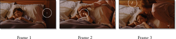
Figure 10-1 Negative dirt appears as white flecks
Figure 10-1 shows a sequence of three frames of enduring maternal charm—except for the obnoxious white dirt flecks popping on and off every so often. Each dirt hit is circled for easy identification. One even lands right on the cherub’s cheek in frame 2. The clone brush is the dominant tool for dust-busting and works by having two circular regions—one where the pixels will be copied from (the source) and one where they will be laid down (the destination). Because the clone brush is copying small sections of the picture from place to place the grain characteristics, color and texture of the region are preserved. The art in dust-busting is to thoughtfully select your source.

Figure 10-2 Slope of the brightness

Figure 10-3 Don’t clone parallel to the slope

Figure 10-4 Clone at right angles to the slope
The brightness of a region is almost never uniform. It invariably “slopes” from dark to light in one direction like Figure 10-2, indicated by the arrow. If the source (marked with cross-hairs in Figure 10-3) is selected parallel to the line of the slope then a darker region will be cloned into a lighter one making a noticeable blunder. The direction of the brightness slope must be carefully observed, then the clone taken at right angles to it like the example in Figure 10-4. This ensures that the source region is the same brightness as the destination region. However, it is sometimes difficult to find these properly sloping regions when dust-busting.
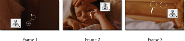
Figure 10-5 Dust-busting frames with a clone brush
Returning to our dirty frames, a closeup of the dirt hit in each frame is shown in Figure 10-5 to show how the clone brush is set up for each fix. In each case the slope of the clone brush source and destinations are perpendicular to any slope in the brightness of the repair region. Frame 1 is in a very dark region so this is somewhat forgiving. Frame 2 is a serious challenge because the cheek has a lot of slope to its brightness but there is not much room to clone from. Frame 3 has the seam in the board to retain so the clone brush is set parallel to it in order to restore the seam over the dirt.
(Download the folder at www.compositingVFX.com/CH10/Figure 10-5 to get these film images and try your hand at dust-busting them.)
10.2 WIRE REMOVAL
The explosion in popularity of wild action films has caused a commensurate explosion in the use of “wire gags” where the hero is trussed up with a harness under his clothes connected to wires and pulleys. On the other end of the wires are the beefy folks that pull on them at just the right moment to boost the hero so he can leap over tall buildings or karate kick 11 bad guys before touching down. Of course, before the shot can be used the wires have to be removed. That’s where we come in.
Our wire removal case study depicts a camera push in to a boy perched precariously on a 5th story balcony. Since OSHA takes a dim view of dropping kids from balconies the production company decided to add the safety wires. Now we get to remove them, starting with the target frame in Figure 10-6. The challenge here is that the camera is moving and the wires cross over a complex background, namely the building. We need to replace the wire with a thin strip of building without the wire. Because of the camera move we have just what we need in Figure 10-7 which will serve as the source frame for a clean piece of building. Note that the wire is covering a different part of the building in Figure 10-6 compared with Figure 10-7, so we will borrow a thin strip of clean building from the source frame to cover the wire in the target frame.

Figure 10-6 Target frame
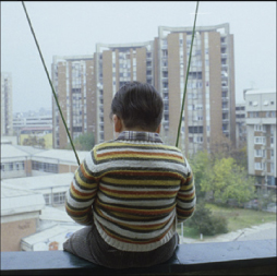
Figure 10-7 Source frame
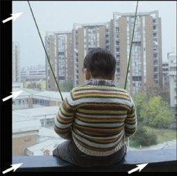
Figure 10-8 Source frame repositioned
The first step is to reposition the source frame to line it up with the target frame. Figure 10-8 shows the source frame repositioned so that the buildings are lined up exactly. The alignment of the source and target frames is checked with a 50% mix in Figure 10-9. You can see that the buildings are right on top of each other but that there are two sets of wires. This is exactly what we want. This means that under the wire in the target frame there is now a clean area of the building from the source frame.
The last step is to “paint through” from the aligned source frame to the target frame using a “clone” brush. A clone brush can also clone between two different images as we are doing here. Figure 10-10 shows the right-hand wire nearly painted out with cloned pixels from the building of the aligned source frame. Since the camera is continuously moving it will be necessary to continuously select new source frames and align them on a frame-by-frame basis over the length of the shot, but the results will be most excellent.
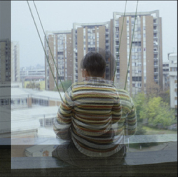
Figure 10-9 Source and target frames aligned
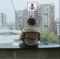
Figure 10-10 Paint through
This wire removal shot had the added complication of a complex background that had to be restored where the wire used to be. If this had been a bluescreen shot it would have been a simple matter just to clone nearby bluescreen pixels over the wires within the same frame, which would avoid the additional step of aligning a source frame to paint through.
(Download the folder at www.compositingVFX.com/CH10/Figure 10-6 to get these film images and try your hand at the wire removal.)
When a motion control shot is done on a model it has to be supported by some kind of armature or rig. Sometimes the armature is static and the camera moves, but the rig can also be a motion control device that moves the model around. Motion control, whether for cameras or rigs, means that the device in question is moved by electric motors under computer control. There are no humans moving the camera or model. The main advantage to this is repeatability. The shot can be filmed in several identical passes, each capturing a different lighting version of the model, then these passes are combined in compositing, very much like the multipass renders for CGI we saw in Chapter 3, Compositing CGI.
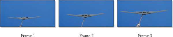
Figure 10-11 Bluescreen motion control shot with an armature rig
The rig removal case study begins with the original B2 stealth bomber motion control bluescreen footage shown in Figure 10-11. The camera is locked off but the model is coming towards camera and rising in frame. The fact that the rig does not change shape but only gets larger and drifts to the right offers an opportunity for a simple solution for this shot.
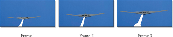
Figure 10-12 Mask motion tracked over the rig
The solution starts by creating a single mask that covers the rig, then motion tracking it over the rig for the length of the shot as shown in Figure 10-12. Because the rig is not changing shape we do not have to roto it. The mask is drawn over the frame that has the most exposed rig, which is frame 3. The shot is then motion tracked in reverse. The last step in the rig removal takes advantage of the fact that the background is a uniform bluescreen surface instead of something complex and detailed such as terrain, so we can simply composite an adjacent piece of the bluescreen over the masked area.
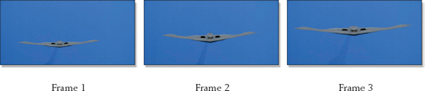
Figure 10-13 Bluescreen shifted over to cover the rig
The final fix is seen in Figure 10-13. For each frame the bluescreen was simply shifted to the right enough to cover the motion tracked mask. A small problem was introduced because the left side of the bluescreen is a bit darker than the center and right. As this darker region was shifted over and composited over the rig it covered it with a slightly darker version of the bluescreen, which you can actually see in the finished composite. The fix is to apply a small color correction to the bluescreen patch to match it up better with the rest of the backing. The uncolor corrected version was used here to show the problem.
The slick thing about this particular example is that the entire rig removal was done procedurally—that is, using rules that the computer follows rather than frame-by-frame manual techniques. The only manual operation was the creation of the single original mask. Everything after that was procedural. Procedural solutions, when they can be used, are faster and give more consistent results than manual techniques.
10.4 HAIR REMOVAL
Even though there is an assistant camera operator (the AC) whose job it is to load film and clean the lens and film gate, it often happens that a hair gets stuck in the gate anyway. This vexing event will afford us the opportunity to examine some more scene salvage techniques and to collect some more insurance money. The hairy frames can be seen in Figure 10-14. The camera is wandering left and right while it tilts up on the shelves and the hair is twitching a bit, as it often does. The hair twitches because the film is advanced from frame to frame, which tends to tickle the hair each time.
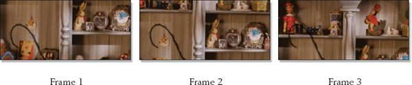
Figure 10-14 Hair removal sequence

Figure 10-15 Hair mask
The hair is constant in size and position (except for the twitching) so we can make a single mask to cover the hair for the whole shot, shown in Figure 10-15. The mask is made large enough to allow for the twitching, and the edges are very soft to blend the edges of the repair.
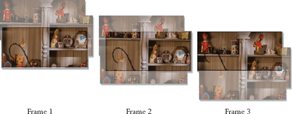
Figure 10-16 Clean plate motion tracked to each frame
The next step is to create a clean plate, which is a single large image that covers all of the area that the hair contaminates as the camera moves around. The clean plate is cobbled together by cutting and pasting together pieces from several different frames to create a “master” hairless version. It is then motion tracked to follow the camera move, which locks the clean plate to the moving shelf like the sequence in Figure 10-16. This puts a piece of clean background behind the hair on every frame. The last step is simply to composite the clean plate over the hairy frame using the hair mask from Figure 10-15. The repaired frames are shown in Figure 10-17.
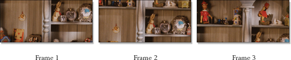
Figure 10-17 Repaired frames
While this technique of motion tracking a clean plate works well, it does introduce a small problem, and that is the grain. The clean plate has “frozen grain” because it is made up of pieces of film frames so the grain in the repaired area will be noticeably static compared with the surrounding area, which can be quite objectionable. The fix is to degrain the clean plate, then regrain just the repaired area each frame using the same hair mask. The degrain operation will soften the clean plate a bit, but a slightly soft area where the hair used to be will be far less objectionable than the frozen grain.
10.5 SCRATCH REMOVAL
Occasionally it happens that the camera negative gets scratched. This can happen in the camera or in the lab. Some small bur presses on the film, and then the equipment drags the film over the bur imparting a continuous scratch down the length of the film. I once saw a 2000 foot scratch where an entire 2000 foot roll of film was damaged. Think of it as job security. Even modern film scanning can introduce a “digital scratch” if the scanning sensor develops a bad spot.
The way to spot the difference between the two types of scratches is to play the footage at speed. The mechanical scratch will weave side to side a bit, but the digital scratch will be rock steady. Knowing this helps with the fix because if the scratch is rock steady we can make a small tight-fitting mask, but if it is weaving the mask has to be wider to cover the moving target. The smaller the masked region to repair is, the more solutions are available and the easier the fix.

Figure 10-18 Scratch removal sequence
Our scratch removal case study begins at frame 1 in Figure 10-18. The scratch is the dark vertical line just left of the man and it passes through three different “zones” in the picture—the wall, his shirt and pants, and the plate on the table. The camera is locked off (not moving), but people move and squirm when they talk. Since the scratch spans these three different “zones” we will need three different fixes and therefore three different masks. Figure 10-19 shows the first mask, the thick white line covering the wall scratch. The mask for the clothes fix is shown in Figure 10-20 and the plate mask is in Figure 10-21. We now have each zone separately isolated over the length of the shot.

Figure 10-19 Wall mask

Figure 10-20 Clothes mask

Figure 10-21 Plate mask
The wall fix is an easy one. Since the wall has no detail other than grain we can use a computer trick that “grows” the edges of the masked region towards the center to fill in the scratch with wall pixels. This edge-growing fix is shown partially completed in the closeup of Figure 10-22. The problem that this process leaves is that the pixels in the fixed region look noticeably smeared horizontally. We will simply use the same mask to regrain this area and be done with it.
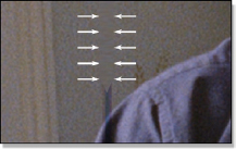
Figure 10-22 Edge-grow technique
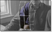
Figure 10-23 Warp and track clothes

Figure 10-24 Clean plate repair
The clothes are fixed by first making one clean “patch” of clothes by painting out the scratch. This clean patch is then tracked and warped over the scratched area like the illustration in Figure 10-23 (the background plate has been made grayscale to show the clean patch). The mask is used to composite just the thin strip needed to cover the scratch. The plate is an easy fix because the camera is locked off. One clean plate is painted (Figure 10-24) and simply composited with the plate mask in Figure 10-21.
10.6 LIGHT LEAKS
If the camera door is not closed tightly, light can leak into the camera body and “flash” the unexposed negative producing a light leak. Which we get to fix. One of the troublesome characteristics of a light leak is that it is not static—it dances around, advancing and retreating from frame to frame. This means that the worst-case frame usually defines the scope of the fix.
In a few cases it may be possible to use some of the techniques seen above to cut and paste and track elements from one frame to another to rebuild the damaged part of the picture, but that is rarely practical for light leaks. The reason is that light leaks tend to damage large areas, not just a dust mote or a hair in the corner. If the picture content is simple, such as a languid pan across the Serengeti Plain, such heroic rescues can work. But if it is more typical picture content the fix is surgery—simply cut out the bad part of the picture.
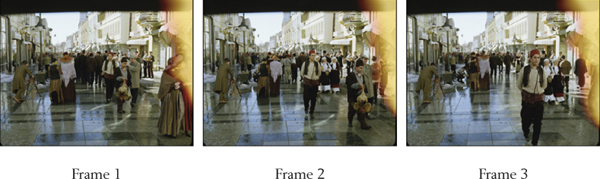
Figure 10-25 Light leak sequence
In the light leak case study of Figure 10-25 you can see how the light leak varies between the three frames. The basic technique is to flip through all the frames of the shot to find the worst-case frame, and then set the size of the crop to that frame in order to cut out all of the damage. In some cases the light leak might be worse at one end of the shot than the other. If so, it might be possible to slowly change the size of the cropped region over the length of the shot to preserve the maximum amount of picture. Obviously the crop window cannot be dancing around trying to follow the light leak frame by frame. To minimize the amount of cropping the cropped region should have the same aspect ratio as the film’s projection format—1.85 in this case—illustrated in Figure 10-26. If the frame were cropped to the full 1.33 frame more of the picture would be lost.
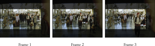
Figure 10-26 Cropped light leak sequence
Once the optimal crop region is found the entire shot is cropped and then scaled up to the original frame width as shown in Figure 10-27. Of course, this will soften the image. You might try sharpening it, but that will kick up the grain. You could try degraining it after sharpening it, but that will soften the picture again. When the client objects you can help him out by suggesting that he avoid light leaks in the future.
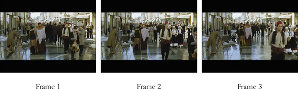
Figure 10-27 Resized frames
10.7 DEFLICKER
There are a surprising number of things that can cause frame flicker, which is a rapid fluctuation in brightness from frame to frame. Strobing lights on the set, camera shutter problems, or mechanical interferences such as helicopter blades are some of the culprits. Each problem introduces a characteristic type of flicker, some easier to fix than others. The strobing light causes just a portion of the scene to flicker, and this may include the faces of the talent. Very difficult. The shutter can cause the entire frame to flicker uniformly. Not too difficult. The mechanical interference will usually affect one region of the image uniformly. Tricky. Fixing these types of problems is called deflicker.
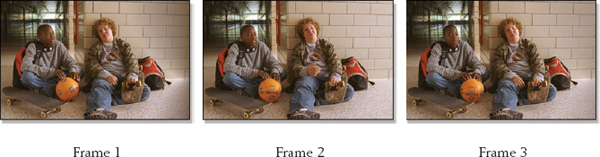
Figure 10-28 Sequence of flickering frames
The deflicker case study in Figure 10-28 represents the kind of problem introduced by strobing stage lights. Note how the right side of the picture fluctuates in brightness from frame to frame. The obvious question that springs to mind about now is how is it possible that nobody on the set noticed the flickering light? The reason is that humans view the scene with their eyes while the camera views it with a shutter that rapidly opens and closes. There is a certain type of light commonly used on the set called an HMI light that is designed to flicker rapidly. The eye doesn’t see the flickering but if it is out of sync with the shutter the camera does. More job security.
A strobing HMI light is causing the right side of the picture to flicker lighter and darker. This part is trivial to deflicker. Just make a clean plate from a frame with the correct brightness and do a soft-edged composite over the right side of the frame. More problematic are the flickering highlights on the talent because people are always moving and changing shape. The fix for this is a hideous process of warping and tracking bits and pieces of adjacent frames over the flickering regions. Thank goodness the insurance is paying for this.
This might be one of those situations where it makes sense not to perform a 100% fix of the problem. In this example, fixing the right side of the frame would be easy, only take a few hours, and might fix, say, 90% of the flickering. The remaining 10% is only slightly objectionable but could take days to fix. The client might find the 90% fix acceptable given the cost of doing the full 100% fix. Saving the client money is a good way to get him to hire you again for his next job.
There is one case where the fix is easy, and that is if the entire frame flickers uniformly as might happen with a twitchy shutter. Here the fix is to essentially perform a frame-by-frame color correction to keep the brightness uniform. There are even dedicated deflicker tools available that are designed to make this particular task easier.