
The trend in visual effects today is an ever-closer integration of digital compositing with the CGI production pipeline. Compositing software is continuously evolving in the direction of more and more support for CGI issues, so the modern digital compositor needs not only to understand how to composite CGI, but a good understanding of CGI itself. In this chapter we will start by taking a look at the composite of a CGI element with its background to introduce the concepts of the foreground layer, the matte (or alpha), the background, and how they go together to create a basic CGI composite. In subsequent sections we build on this to introduce the complexities of a more typical production shot. We will also be taking a close look at the interface between CGI and digital compositing—the boundary where they meet and how the workflow in the CGI pipeline affects the digital compositor.
In the not too distant past a CGI object was rendered whole and given to the compositor to composite into the scene. Today, the standard practice is to render each CGI element in a series of separate passes, or layers, each layer containing different color and lighting information which the compositor then combines, merges, and massages to create the final look. In addition to this multipass compositing there is also multiplane and depth compositing. One must not just understand the distinction but also know how to work with them.
CGI is also a rapidly evolving technology so it is essential for the modern digital compositor to stay abreast of developments, or risk not being hired for lack of background. For this, we will take a look at both sims (simulations) and particle systems. Sims are a critical and continuously expanding development that actually creates the animation for many CGI objects. Particle systems are responsible for generating what used to be some of the more difficult classes of CGI objects – amorphous elements such as clouds, water, smoke, and fire. Particle systems are now extremely prevalent and even starting to show up in advanced 2D systems.
Another major trend in the world of compositing visual effects is the addition of 3D compositing to the 2D compositing job. The major software packages now support 3D compositing, which represents a major shift in the workflow and expectations of the compositor. The compositor must now have a basic understanding of 3D and add new skills such as camera tracking.
3.1 THE CGI COMPOSITE
A composite requires three elements: a foreground image, a background image, and a matte. Only some of the pixels in the foreground and background images are to be used in the final composite so the computer needs to know which pixels to use where. It is the matte that tells the computer which pixels to use from the foreground image and which pixels to use from the background image.
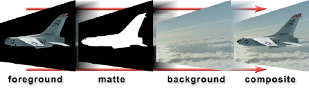
Figure 3-1 The matte controls the foreground and background mix
Figure 3-1 illustrates how the foreground and background images are layered using the matte to tell the computer which pixels to use from the two layers. Where the computer finds a white pixel in the matte it will use a pixel from the foreground layer. Where it finds a black pixel it will use a pixel from the background layer. And, very importantly, where it finds a gray matte pixel somewhere between black and white it will mix the foreground and background pixels in the same proportion. For example, a 75% white matte pixel will result in 75% of the foreground being mixed with 25% of the background in the composite. More on this exciting concept later.
The folks that make CGI prefer to call their mattes the alpha channel or just the alpha. The alpha channel of a CGI image is simply the matte that the computer has calculated for a CGI object, but they needed to have their own special term. In the next chapter we will take a look at bluescreen compositing and see how we get to make our own mattes for the bluescreen layer. Great fun.
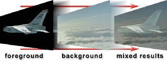
Figure 3-2 Without a matte the results are mixed
So what would happen if you tried to do a composite without a matte? Figure 3-2 shows the sorry results. The computer has no guidance as to when to use the foreground or background pixels so the results become a bland mix of the two. It seems you just can’t do a nice composite without a matte.
3.1.1 Scaling the Background
So now we know that the matte is the grand arbiter of the composite, but how is it actually used? It clears the background pixels to black in order to make a “hole” for the foreground object to fit into like the example in Figure 3-3. This is done by multiplying the matte and the background plate together, which scales some of the background pixels to black. Note how the scaled background of Figure 3-3 looks like a perfect match to the foreground in Figure 3-2. When the foreground and scaled background layers are brought together for the actual composite they will fit perfectly because they share the same matte.
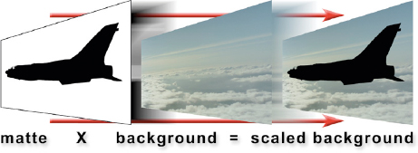
Figure 3-3 The scaled background
Now let’s consider how the matte actually scales the background plate. Note how the matte in Figure 3-3 has been inverted (black and white swapped) compared with how it looked in Figure 3-1. The jet is now zero black and the surrounding area is now white. Recall from Chapter 2 what happens when a mask and an image are multiplied together—the white parts of the mask preserve the pixels in the image while the black parts scale them to zero. When the inverted matte in Figure 3-3 is multiplied by the background plate, the RGB code values where the jet will go become zero black. This is necessary to set things up for the final step in the composite.
3.1.2 Semi-transparent Pixels
So far, we have been talking about the matte only in terms of black and white pixels. However, not every pixel in the composite is either 100% foreground or 100% background. There are a lot of pixels that are a mix of both layers and these tend to be the most important pixels for a convincing composite. They can generally be found in three places. First, they are found in any semi-transparent objects in the foreground, such as smoke or a jet canopy, for obvious reasons. Second, any motion-blurred part of the picture, where something has moved so fast that it has smeared edges, will produce semi-transparent pixels. And third, they are found where the edge pixels of the foreground object meet the background. These pixels are always a mix of the two layers, not 100% of either.
To address these types of situations the matte must have gray pixels to represent the degree of transparency. The “density” of a matte pixel refers to how transparent it is. If it has high density it is not very transparent and as it approaches white it becomes opaque. Low-density matte pixels are highly transparent and as they approach black they become totally transparent.
Utilizing our newfound knowledge of multiplying images from Chapter 2, let us trace how a mixed pixel is calculated from a semi-transparent matte pixel. Following along in Figure 3-4, (1) is a light gray matte pixel with a density value of 0.75. It is multiplied by the foreground pixel (2), a typical skin tone, to produce the scaled FG pixel (3). It now has 75% of the brightness of the original. The 0.75 matte pixel (1) is then inverted to make the 0.25 density matte pixel (4) at the lower left. This inverted matte pixel is multiplied by the background pixel (5), a typical sky value, to produce the scaled BG pixel (6), which is now only 25% of its original brightness. The scaled FG (3) and the scaled BG (6) are then summed (added) to create the final mixed pixel (7) which contains 75% of the skin and 25% of the sky.
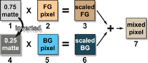
Figure 3-4 Semi-transparent pixel calculations
3.1.3 Summing the Layers
It turns out that, unlike the background layer, a CGI image has already been scaled by its matte (I mean alpha) when it comes to you, so it is ready to composite. Whereas, as we saw in Figure 3-3, the background layer must first be scaled by the inverted alpha to prepare it for the actual composite. Once this is done all that is needed is to simply sum (add) the two layers together. The pixels of the CGI layer and scaled background are lined up together, and then the computer simply sums them together on a pixel-by-pixel basis to produce the pixels of the final image—the composite. A black pixel has a value of zero and any number plus zero is the original number, so a black pixel summed with a colored pixel will always result in the colored pixel.
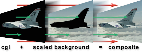
Figure 3-5 Sum the scaled layers to make the composite
You can see this in action in Figure 3-5 if you follow the top green arrow starting at the CGI layer on the jet’s tail and follow it through to the scaled background pixel, which is black. After they are summed in the composite image that pixel is the color of the jet tail. Following the lower green arrow, it starts on the CGI layer at a black pixel and goes to a cloud pixel in the scaled background. When these two pixels are summed together in the composite the result will be the cloud pixel. After scaling the background layer by the alpha channel it can be merged with the CGI layer using this simple addition operation to make the finished composite.
3.2 MULTIPASS COMPOSITING
It turns out that the real world is annoyingly complex. When we first started making CGI objects for movies they did not look very realistic. The movie The Last Starfighter leaps to mind. Delightful movie, but no attempt was made to make it photorealistic as that was far out of reach in those days, way back in 1983. As the founding fathers of CGI studied the problem they discovered what I meant by the real world is annoyingly complex. You need to account for a multiplicity of complex lighting, materials, surface attributes, and atmospherics to get a photorealistic CGI object. As the computer models got more complex, the rendering times skyrocketed. Rendering times of 24 hours per frame are legendary. Something had to be done.
The solution to this problem (besides faster computers and more efficient software) was to render each of these multitudes of surface and lighting attributes as separate images, or passes. These multiple passes are then combined by the compositor, and in so doing the compositor, being the consummate artist, also makes the final adjustments and color corrections that give the shot its final look. This is a much faster workflow because the compositor can turn out a new version in a few hours when the look has to be adjusted—and it always has to be adjusted. If all the passes were initially rendered together, changing the look would require rerendering all of the CGI, which can take days, or even weeks. One nice thing about this arrangement is that it is now the digital compositor that applies the finished look to the shot, raising the importance of our artistic contribution to the job.
Here we will look at an example of a simple multipass CGI render to see how the layers go together to create the final look. Keep in mind that this is but one example showing a CGI object rendered in five passes—diffusion, specular, occlusion, shadow, and reflection. Other situations will require not only a different number of passes but also different types of passes. Big budget feature films with 20 passes per object are not unusual.
3.2.1 Diffuse and Specular Passes
We start with the diffuse pass shown in Figure 3-8. The diffuse layer of a CGI object represents the “flat” light that is reflected from the surface, as if it were made of felt. No shiny bits. Note that it has shading, which means those parts that face towards the light are brighter than the parts that face away from the light. We have one strong light to the upper right of camera and a softer light to the left of camera. Often the matte itself is also rendered as a separate pass like the example in Figure 3-6.
The next pass is the specular pass in Figure 3-7. This represents just the shiny bits of the rendered surface. Note that it is a different color than the diffuse layer. Specular highlights can either take on the color of the light source, the color of the surface material, or change color based on the viewing angle, all depending on what kind of material you are modeling—plastic, metal, wood, etc. And different metals have different specular behaviors. Like I said, annoyingly complex.
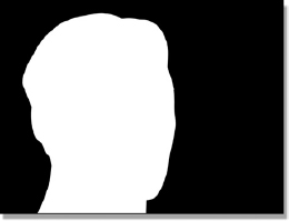
Figure 3-6 Matte
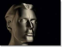
Figure 3-7 Specular pass
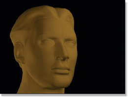
Figure 3-8 Diffuse pass
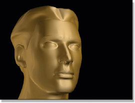
Figure 3-9 Specular highlights added
The specular highlights have been added to the diffuse layer in Figure 3-9. In this particular case the specular layer was first darkened, and then actually added to the diffuse pass with an addition operation, but one could choose any number of image blending operations to combine the passes. Each blending method would have resulted in a different look. Choosing the blending method for each layer is one of the creative decisions that the compositor must make.
3.2.2 Occlusion and Shadow Passes
Next we will consider the occlusion pass, or more formally, the ambient occlusion pass, shown in Figure 3-10. Ambient light is the light bouncing between objects in a scene, as opposed to the light coming directly from light sources. Ambient occlusion considers how this ambient light is blocked, or occluded, between and within the CGI objects, which casts subtle shadows and darkens regions in the scene. Note where the dark areas are in Figure 3-10—where the eyelids meet the eyes, above the ear, in the nostrils. This occlusion pass would look the same even if you moved the lights around in the scene. The occlusion pass has been added to the head from Figure 3-9 using a multiply operation to create the new version in Figure 3-11.
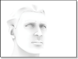
Figure 3-10 Occlusion pass
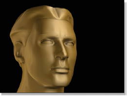
Figure 3-11 Occlusion added
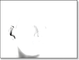
Figure 3-12 Shadow pass
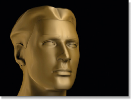
Figure 3-13 Shadow added
Next we will add actual shadows to the head using the shadow pass from Figure 3-12. This too is multiplied by the previous version in Figure 3-11 to produce the next version of the head in Figure 3-13. Note the deep shadow in Figure 3-13 in the ear and to a lesser degree on the neck. Now compare those same two regions in Figure 3-11 and Figure 3-13 to see the effect of the shadow pass.
3.2.3 Reflection Pass
The last pass of our “simplified” example of multipass CGI compositing is the reflection pass. For this pass the CGI surface attribute was set for 100% reflectivity as if it were a mirrored surface, then the intended background image was reflected off the surface. The results are shown in Figure 3-14 and the background plate is shown in Figure 3-15. Again, there are many choices for how to combine the reflections, but in this example a screen operation was used to create the final version in Figure 3-16. This version of the head was used for the final composite in Figure 3-17 using the separate matte from Figure 3-6.
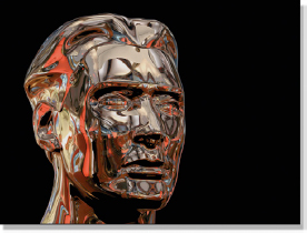
Figure 3-14 Reflection pass
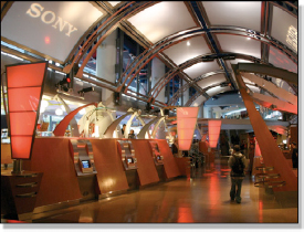
Figure 3-15 Background
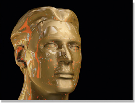
Figure 3-16 Reflection added
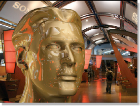
Figure 3-17 Final comp*
The startling truth about this multilayer compositing example is that it is a simplified case. To create a truly photorealistic gold statue would require many more passes than we have here, including a grunge pass. A grunge pass is a subtle layer of dirt and debris that roughs and dirties up the otherwise perfectly smooth and mathematically pristine surface of a typical CGI object. Made famous by George Lucas during the first Star Wars, he wanted all of his space hardware to look used to give it more texture and realism. Up to that time model makers would never dream of dirtying up their meticulously crafted models, so visual effects shots had a “too clean” look. Now that CGI is the dominant visual effects technology the grunge layer is used to add that touch of life.
3.2.4 Creative Control
With the CGI object rendered in multiple separate passes it now becomes possible to dramatically alter the final look of the composite just by adjusting the layers. These variations can come from two completely different directions—how the layers are combined and how they are color corrected.
In the examples above we saw various layers combined using add, multiply, and screen operations. These image blending operations and many others are discussed in Chapter 7, Image Blending. Changing the image blending operation between layers completely changes the results and this is one method of creative control the compositor has in the final look of a CGI composite. The other creative control is the color correction. Not just color correction of the finished composite but of each render pass that makes up the finished composite—plus the finished composite.
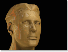
Figure 3-18 Soft
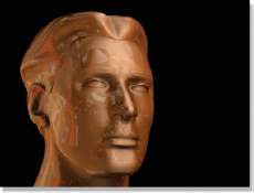
Figure 3-19 Copper
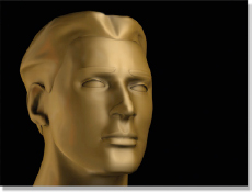
Figure 3-20 Brush
Some examples of these variations are seen here starting with Figure 3-18. Compare this head with the one in Figure 3-16. It looks softly lit and is much less shiny. Both the specular highlights and the reflections were turned down to get this look. Figure 3-19 takes on a copper look by applying a color correction to the original diffusion pass. The reflections were also turned down a bit and given a gentle blur to reduce the shininess of the surface. A brush finish, meaning not very shiny and reflective, was achieved in Figure 3-20 by turning the reflection pass way down and giving it a big blur. When you factor the possible variations created by altering the image blending operation for each layer, along with varying the color correction for each layer, you begin to see the enormous range of creative control available to the compositor when working with multipass CGI.
(Download the folder at www.compositingVFX.com/CH03/MultiPass Compositing to get these images and try your hand at compositing them.)
All of these possibilities introduce a major problem. Suppose our gold statue man is to appear in 35 shots, which will be composited by six different compositors. If each compositor dreams up his own recipe of layer combination and color correction it will be impossible to maintain continuity from shot to shot. Each shot will look different. It will not even work to provide one “hero” color corrected image for everyone to look at because there are a thousand ways to achieve that one look. What needs to be done is to have a senior compositor set up the layer combining strategy as well as the color correction operations in a compositing script. This script, along with the hero image, forms the “recipe” for the composite and is made available to all of the compositors on the team to use as a reference. Variations will be needed to refine the final look to allow for different lighting conditions in the various shots, but at least they will all be starting from the same reference point.
3.3 DEPTH COMPOSITING
Depth compositing is one of the many examples of the trend in the visual effects industry to have the 2D compositing more closely integrated into the 3D production pipeline. The idea behind depth compositing is to add a 5th channel to the RGBA image we met in Chapter 2 which carries depth information about the objects in the frame. Since the Z axis is the depth into the scene, this information has been named the Z channel, so now we have an RGBAZ image. Most digital compositing programs can read the Z channel and use the depth information to automatically set the layering order to place the various objects in front of and behind each other. The depth of an object in the scene is indicated by how bright or dark its Z channel data is. Objects close to the camera are typically whiter, and objects further away are darker. Your system may vary.

Figure 3-21 Depth composite
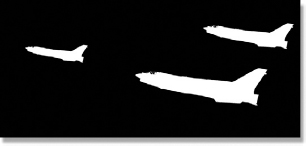
Figure 3-22 Jet alpha channel
Our case study of the depth composite starts with the finished composite in Figure 3-21 that shows a formation of CGI jets doing some risky nap of the earth flying. Note how the nearest jet appears both behind the rock on the right and in front of the rock on the left. This is the depth composite in action. Figure 3-22 shows the typical alpha channel for the jets that represents the transparency of the CGI objects. They are not clipped or cut off in any way to fit to the rocks.

Figure 3-23 CGI jets

Figure 3-24 Background
The original CGI jets are shown in Figure 3-23 and the background for the composite is in Figure 3-24. For the depth composite to work, the compositing program will need the Z channel depth information for all three jets plus the rocks from the background. The Z channel for the jets is easy because virtually all CGI programs now support Z channel data. Since the computer is rendering the jets, it knows darn well how far in Z they are from the camera. The rendering program is simply told to include the jets’ Z channel in the render, which is shown in Figure 3-25. Compare the Z channel data with the CGI jets in Figure 3-23 and you can actually see a correlation between the apparent distances of the jets and the brightness of their Z channel—the further from the camera, the darker the Z data.
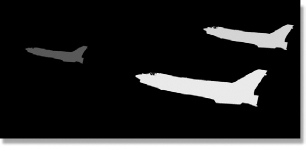
Figure 3-25 Jets’ Z channel
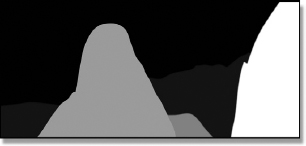
Figure 3-26 Background Z channel
The background is live action, not CGI, so the computer does not have any depth information about it. This will take a human touch. Figure 3-26 shows the Z channel for the background with closer objects whiter and further objects darker. This Z map was painted by hand with Adobe Photoshop, and then given to the compositing program. It now knows the depth of all the objects in the scene and will layer them correctly. One additional trick with the Z channel is to use its depth data to add a depth haze to the composite. Nice. Now that you appreciate how this all works, you can go back and admire the finished depth composite in Figure 3-21 one more time.
This is all marvelous and wonderful, but why would you want to do it? Because if you don’t do it then each jet will have to be composited individually and the layering order with the rocks will have to be set by hand. This is not too serious a prospect for three jets, but what if you had 30 CGI objects? Or 300? Now imagine a whole squadron of jets circling one of the rocks, first in front of it then behind it, changing the layering order every few seconds. Yikes! You would quickly begin to wish for an automatic method of keeping the layering order correct. You would wish for depth compositing with Z channel data. If the background is also CGI the computer can render a Z channel for it too, making our lives even ee-Z-er. Sorry about that.
(Download the folder at www.compositingVFX.com/CH03/Depth Compositing to get these images and try your hand at compositing them.)
3.4 MULTIPLANE COMPOSITING
Multiplane compositing bridges between the 2D and 3D departments. It composites 2D images, but does it in a 3D environment within the compositing program. Referring to Figure 3-27, the 2D images are spread out in 3D space from front to rear and a computer camera is positioned at the far left to frame them all. This is a true 3D environment where the image planes can be moved front to rear and they will shrink and grow with perspective. The camera can also be moved and the image planes will behave as though the images were on invisible sheets of glass that don’t shatter as the camera moves through the scene.
The difference between depth compositing and multiplane compositing is that depth compositing is strictly a 2D event with the Z channel simply controlling the compositing layer order. Multiplane compositing has no Z channel and is a true 3D environment with a moving 3D camera, even though the images are just 2D elements. The image layers can be CGI, live action footage, digital matte paintings, pictures of your mom, or any other image source you have. This technique is commonly used to combine CGI with live action scenes because it can utilize 3D match move data, which we will learn all about in Chapter 8.
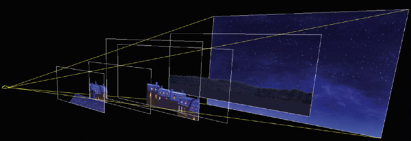
Figure 3-27 Multiplane composite setup
When the camera moves through the scene the image planes grow and fly past the camera just like they should. The night village multiplane sequence in Figure 3-28 shows three frames of a camera flyover using the setup in Figure 3-27. You can see each layer of the multiplane composite change size and position while the far background plate of the sky remains locked at infinity just like a real sky.
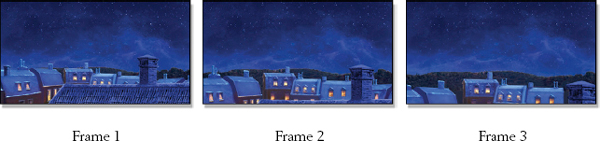
Figure 3-28 Multiplane composite sequence with moving camera
The limitation of all this is that the images are in fact just 2D elements so the effect cannot be pushed too far or the viewer will see your 2D-ness. Where this method really shines is with match move data where the live action scene has been motion tracked to extract the 3D motion of the camera filming the scene. This information can then be used to add elements to the shot and lock them to the background layer even while the camera is moving. There is more information about the match move process in Chapter 8 in case you just can’t wait.
(Download the folder at www.compositingVFX.com/CH03/Multi Plane Compositing to get these images and try your hand at compositing them.)
3.5 SIMS
“Sims” is short for “simulations,” a very important and rapidly expanding aspect of CGI for creating animation. A sim is a computer simulation of some natural phenomena, such as weight and gravity. A simple example would be to build a 3D ball, assign it a mass, and then declare the strength of gravity. Release the ball on frame one of an animation and the computer can model it gaining speed and falling faster each frame over the length of the shot. Add to the 3D rendering program a motion blur calculation and you would end up with an image like the gravity example in Figure 3-29. The sim can be made even more accurate by including the shape of the ball and wind resistance factors.
There are three compelling reasons for using sims. The first is that it can be extremely difficult and complicated for an animator to correctly animate physical objects any more complicated than a bouncing ball. Even with the simple bouncing ball, what if you needed a thousand of them? The second reason is that a sim is invariably much more realistic than what a simple human could conjure up. Third, you can “dial in” the sim behavior to achieve the creative intent of the director, even if that means cheating the physics a bit—as long as it doesn’t cross the line and start looking wrong. Remember, in visual effects, if it looks right, it is right.
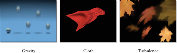
Figure 3-29 Typical sim examples
Consider the example of the flapping cloth in Figure 3-29. Can you imagine pushing and pulling on dozens of control points scattered all over the cloth to simulate Superman’s cape flapping in a supersonic slipstream? Not only would this be immensely time-consuming, but it would also look awful. No human actually knows how cloth behaves under the laminar flow of a supersonic wind. But the computer does. The animator simply adjusts the parameters of the simulation and the material’s attributes until the desired action is achieved instead of adjusting animation control points.
In addition to building a synthetic world of weight, gravity, wind, fabric stiffness, and almost any other property you can imagine, turbulence can also be added. These are mathematical whirls and vortices of wind or water which then shove 3D objects around with a realistic random motion like the turbulence example of the blowing leaves in Figure 3-29. The 3D animator has control over how strong it is and can “dial it in” to get any desired amount of turbulence.
Sims go far beyond the few simple examples here. They can simulate the collapse of an entire building or the bending of a steel bar under a massive load. In the last few years it even became possible to simulate the behavior of liquids, most especially water, although this is still extremely difficult and computer intensive. Sims can also simulate the collision of solid bodies, such as dumping a truckload of bricks on the ground, or even elastic bodies, such as bouncing rubber balls. The bouncing, flowing hair on a CGI character is often animated with a hair sim.
Complex sims such as these not only require very sophisticated software but also very powerful computers because of the shear number of calculations required to compute all of the possible interactions of all the objects in the scene. No wonder they are a recent development. Sims are guaranteed to become progressively more pervasive in visual effects because they solve a critical need in visual effects and are becoming ever more capable and easier to create.
An entire other class of 3D animation are what are called particle systems. Particle systems are used to create images that are made up of thousands or even millions of tiny particles, such as the fog, rain, and smoke illustrated in Figure 3-30. The concept here is that the 3D animator first defines the attributes of his particles—size, color, transparency, softness, etc.—and then gives them a “life.” That is, each particle is born, lives, and then dies. These attributes are not individually assigned to each particle, of course, but are instead done by declaring rules and setting parameters with statistical distributions over all the particles so that each is unique, but still conforms to the overall behavior of the “particle cloud.” Simply by changing the rules and parameters a particle system can generate a wide variety of amorphous photorealistic phenomena such as fog, rain, smoke, dust, snow, fire, tornadoes, clouds, as well as Tinkerbelle’s trailing pixie dust.
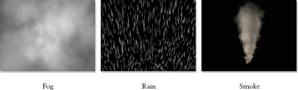
Figure 3-30 Classic particle system examples
The particle system creates the item of interest by generating a huge number of particles, which are typically given some built-in motion such as the smoke example in Figure 3-30. In addition to this inherent motion, sims can be added to stir things up. For example, a wind force could by applied to the smoke particles and cause the smoke to drift off to the right. Turbulence could then be added to the wind to swirl the smoke particles. When you add sims to particle systems then throw in advanced lighting and rendering capabilities you begin to see how these separate systems combine together to build a progressively more sophisticated and photorealistic image.
There is one surprising aspect shared by both particle systems and sims, and that is you cannot start rendering them on frame one. Consider, for example, the smoke in Figure 3-30. On frame one the particles are just starting out and have not begun rising yet so they are just sitting on the floor. The smoke may not achieve the full form you see here until, say, frame 100. Only then can the image render begin. In actual practice, the process of outputting the rendered images does begin on frame one, but the particle system and the sim have actually been started on frame −100 (minus 100). This way the particles have 100 frames to populate the screen and take on their full form before the first image is output.
The compositing process itself is not really affected when working with sims because they are just another way to animate 3D objects. The compositing program does not know or care which agent—man or machine—moved those objects. Particle systems, however, represent a different case. They are typically amorphous and often semi-transparent or even glowing and the particle system software must generate an appropriate alpha channel. The compositor must also make creative decisions as to how to composite the particle element—a typical composite, an add-mix, a screen operation, or some other image combining strategy.
3.7 WORKING WITH PREMULTIPLIED CGI
There is a bit of a technical issue about compositing CGI that needs to be addressed, and that is the issue of premultiplied and unpremultiplied CGI. To understand this issue we will need to dive inside the CGI rendering process for a moment. So why do we care about the grizzly innards of a CGI render? There are three reasons. The first is that you need to get this issue right in order to properly composite, color correct, and transform CGI elements. Second, getting this wrong adds dark edges to your CGI composites which in turn spawns a cascade of compensating errors in a frantic attempt to make them go away. Third, you may get work in a visual effects facility that surprises you by handing you unpremultiplied CGI to composite, so this information will help you to avoid that “deer caught in headlights” look.
Some of the difficulty of this subject comes from the unfortunate use of the awkward CGI terms premultiply and unpremultiply. It might help to realize that “premultiply” merely means that the RGB image has been multiplied by the alpha channel like we saw in section 3.1.1 Scaling the Background above, while “unpremultiply” means that it hasn’t. To see how scaling the RGB code values of the CGI element by multiplying it with its alpha channel affects our compositing, we now dive inside the rendering of a CGI object.
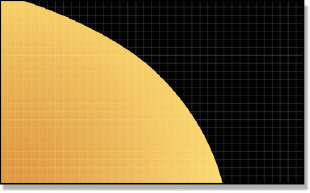
Figure 3-31 Actual geometry
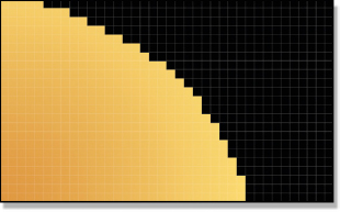
Figure 3-32 Unpremultiplied
Our story starts deep inside the 3D program where the actual geometry of the CGI object resides, visualized in Figure 3-31 as a closeup of a curved surface. At this point it has not been rendered so it doesn’t know or care about pixels. But when it comes time to be rendered, the resulting image must be divided up into discreet pixels, which are represented by the feint lines in Figure 3-31. The problem that the rendering program has is that at the edges of the geometry it cuts across pixel boundaries only partially covering them. The edge may cover one pixel by 30%, but another by 90%.
This problem is universally solved by breaking the render into three steps. The first step is to render the edge of the geometry as if it covered all of its pixels by 100%. This produces an image like the unpremultiplied image in Figure 3-32 where the edges are jaggy. It is called unpremultiplied because it has not yet been scaled by its alpha. Don’t worry, we are not done yet. The second step is to render the alpha channel shown in Figure 3-33. This channel represents the percentage of each pixel that is covered by the geometry. If the geometry covers a pixel by 100%, its alpha pixel will be 100% white. If the edge of the geometry covers a pixel by 30% its alpha pixel will be 30% white, and so on.
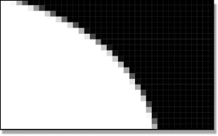
Figure 3-33 Alpha channel
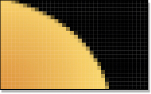
Figure 3-34 Premultiplied
The last step is to multiply the alpha channel (Figure 3-33) by the unpremultiplied version (Figure 3-32) of the render to produce the premultiplied version shown in Figure 3-34. This is the familiar form we normally get CGI delivered in. However, it is not the best form for color correcting the CGI. The unpremultiplied version is.
3.7.1 Color Correcting
That’s right—you want to perform color correction operations on the hideously jaggy unpremultiplied version of the CGI shown in Figure 3-32. The reason is that if you perform color correction operations on the premultiplied version (Figure 3-34) it can introduce color artifacts around the edges of the composited CGI. Why this happens is too messy to go into in an introductory book like this, but you will find all the gory details in my more advanced book Digital Compositing for Film and Video if you would really like to know.
So, if you are only given the premultiplied CGI, how do you get back to the unpremultiplied version? Remember how multiplying the unpremultiplied version by the alpha channel created the premultiplied version? This is a reversible process, so we can simply divide the premultiplied version by the alpha channel to revert back to the unpremultiplied version. This is referred to as unpremultiplying the CGI. The whole procedure, then, is first to divide the CGI by its alpha channel, perform the color correction, and then re-multiply the results by the alpha channel. All compositing programs offer such capabilities, but you may have to rummage through the manual to discover what your software calls it. One more point—all this multiplying and dividing of RGB values is hard on 8-bit images so they should be promoted to 16 bits prior to the unpremultiply operation. They can then be restored to 8 bits after the re-multiply operation if needed.
Having said all this about how to properly color correct CGI, let me now say it is OK to skip all of it if you are only making minor color corrections. Perhaps you only need to increase the brightness a bit or tap down the gamma. If the color corrections are small then the introduced errors are small and will not be noticeable. My advice is to try the color correction first on the premultiplied CGI, and then inspect the results carefully. You will often get away with it. To be safe, you could apply an exaggerated version of the color correction (twice the intended brightness, for example) then check for problems. If none are found, dial it back to the real setting and move on.
3.7.2 Transformations and Filters
While color correction operations should always (technically) be done on unpremultiplied versions of the CGI, all transformations (move, scale, rotate, etc.) and filters (blurs, median filters, etc.) should be done on the premultiplied version. If transformations or filters are applied to the unpremultiplied version, edge artifacts can show up in the composite. Why this happens is another arduous story, so we can’t get into it in this book. It’s just the rule. But we can see what will happen.
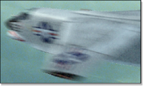
Figure 3-35 Unpremultiplied
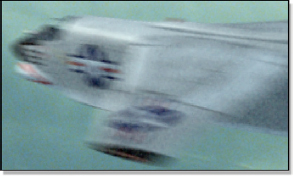
Figure 3-36 Premultiplied
The unpremultiplied jet in Figure 3-35 is an example of the edge artifacts that are introduced by simply rotating it 10 degrees, and then re-multiplying it for the final composite. Some of the pixels around the outer edge of the jet have become badly brightened, especially on the top and bottom edges. Compare that with the premultiplied version in Figure 3-36, which has very nice edge pixels. In some compositing programs the edge artifacts may be dark instead of light, depending on how they perform the unpremultiply operation. Tragically, the dark version of this artifact can look very similar to the artifact introduced by a very common mistake, which we will examine next.
3.7.3 The Common Mistake
Most compositing programs assume that the CGI you are compositing is premultiplied. However, virtually all of them allow you to switch the compositing operation for either premultiplied or unpremultiplied CGI. If you tell the composite operation that the CGI is unpremultiplied, then it will apply a premultiply operation during the composite. However, if you have performed an unpremultiply operation for color correction you may or may not have reapplied the premultiply operation prior to the composite operation, so it will have to be set for … something or other.
This can get confusing. The common mistake is to inadvertently tell the compositing operation to apply a premultiply operation to CGI that is already premultiplied. If that happens, the edges of the CGI will turn dark like the double premultiplied edges example in Figure 3-37. The example in Figure 3-38 is set up correctly, while Figure 3-37 sports the dark edges of a double premultiply operation. The reason this happens is because the premultiply operation naturally darkens the edges. If the CGI is unpremultiplied (like Figure 3-32) then this is a good thing. If the edges are already premultiplied (like Figure 3-34) then this is a bad thing and you wind up with the double darkened edges of Figure 3-37.
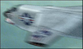
Figure 3-37 Double premultiplied edges
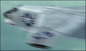
Figure 3-38 Normal edges
If you see dark edges like this around your CGI composite you can usually assume that the premultiply operation has been applied twice and start troubleshooting your composite accordingly. The most likely fix is to go into the composite operation and find the button to press to tell it NOT to perform a premultiply operation. However, sometimes the edges of the CGI are naturally dark and you are not sure if things are set up correctly. Fear not, there is a simple test that you can perform to confirm that you have set up the composite correctly (or not).
Simply switch out the background image with a plate of zero black so that the CGI is composited over the zero black plate. If the composite is set up correctly the black composite can be compared with the original CGI element (which is already over zero black) and toggling between the two in the image viewer will show that they are identical. If the black composited version appears to shrink around the edges compared with the original, then there is a double premultiply. To be sure, there are other compositing problems that can also produce similar looking dark edges, but this is one of the most common causes so it is the first place to look.
3.8 3D COMPOSITING
A recent trend in compositing visual effects is the addition of 3D compositing to the compositor’s job description. 3D compositing is not to be confused with compositing 3D, where 3D objects have been rendered by the 3D department, and then the images given to the 2D department to composite. 3D compositing actually has a limited 3D system built into the 2D compositing software so the compositor can render 3D objects himself to include in the composite. In this first section we will gain an understanding of what 3D compositing is, then in the subsequent sections we will see what you can do with it. It turns out that there is a staggering number of really cool things that can be done with 3D compositing.
One of the main applications of 3D compositing is to rephotograph live action elements with a 3D camera that duplicates the live action camera used to photograph the original scene. These live action elements can be moving clips, photographic stills, Adobe Photoshop paintings, or anything else made up of pixels. Actual 3D objects can also be included in the scene and rendered with lights and surface properties. Since the intent of the 3D compositing is mainly to rephotograph other pictures with matching camera moves, it is not a full-up 3D animation system like Maya. It is a very restricted subset of all that the 3D animation systems can do.
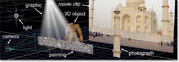
Figure 3-39 A typical 3D compositing scene
Figure 3-39 illustrates a typical 3D compositing scene. The scene contains a painting of the rock wall, a photograph of the tower, a 3D object to be rendered, plus a graphic element to make the light rays. The 3D scene includes a light to illuminate the 3D object, the movie clip for the background, and the 3D camera to rephotograph it all. If the camera is locked off (not moving) then this scene might be done as a straightforward 2D composite. However, most visual effects scenes have moving cameras so rephotographing these elements together in the correct 3D space results in all of the elements moving with the correct perspective and parallax.
(Download the folder at www.compositingVFX.com/CH03/3D Compositing to get these images and try your hand at compositing them.)
3.8.1 The 3D Compositing Environment
What’s in a 3D compositing system is illustrated in Figure 3-40 from a state-of-theart compositing program (Nuke). There are simple geometric primitives (spheres, cubes, cards, cylinders) which can be placed within a 3D environment. Texture maps (images) can be attached to them, and then a 3D camera is placed in the scene to render the results. Lights can be placed in the scene, and shaders (surface attributes) can be assigned to the geometry. To be sure, large and complex 3D objects that were created in sophisticated 3D programs can be imported along with their cameras, lights, and texture maps.
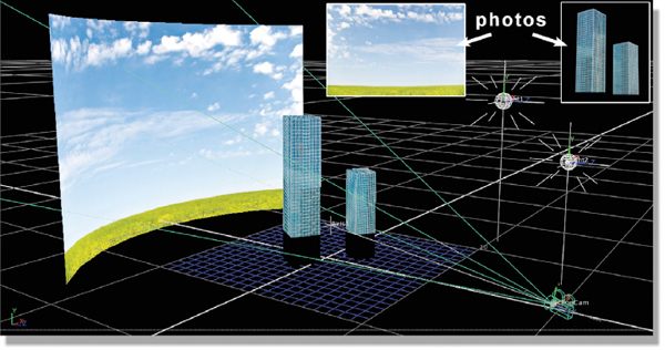
Figure 3-40 The simplified 3D world within a compositing program
As an illustration of the power of 3D compositing, consider the shot illustrated in Figure 3-40. The only things imported were the two photos in the white insets: the sky and buildings. These were then projected onto simple cubes and cylinders and then photographed with a moving camera. The result is the 3D scene with the camera orbiting around the two buildings shown in Figure 3-41. And it looks totally photorealistic because it was created with photographs. This shot only took a couple hours to set up so this is an extremely efficient way to make a 3D shot.
(To see a movie of this shot download www.compositingVFX.com/CH03/Figure 3-41.mov)

Figure 3-41 The movie clip rendered from the 3D setup in Figure 3-40
3.8.2 Placing 3D in Live Action
Placing 3D objects in live action is a staple of the visual effects industry and a core requirement for compositing. Without 3D compositing the CGI would have to be rendered in the 3D department and then handed to the 2D department for compositing. If there were any changes required—and there are always changes required—the compositor would have to communicate that to the 3D artists who would then re-render the CGI and hand it back to the compositor. With 3D compositing the compositor renders his own 3D and composites it directly. If there are any changes needed the compositor makes those changes and re-composites. It is a much tighter workflow: more efficient, and less expensive.
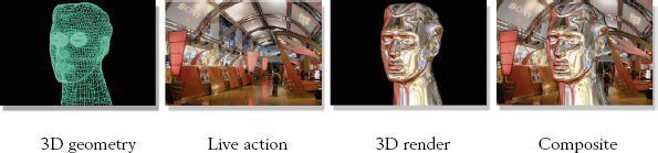
Figure 3-42 3D rendered and composited into live action
Figure 3-42 illustrates a 3D compositing workflow where a 3D object is to be placed in a live action environment. It must be pointed out that the 3D compositing program has only limited 3D capabilities, so it is not capable of modeling or animating the 3D head shown here. That is done in the 3D department. However, the compositor can bring very complex 3D geometry into his compositing program, then using the live action clip, perform the 3D render, and then composite it over the live action background.
3.8.3 Placing Live Action in 3D
The other staple of 3D compositing is placing live action in 3D environments. Here the live action characters are filmed on a bluescreen or greenscreen and then keyed out and composited in an entirely synthetic world created in 3D. This is done when the “world” they are to be integrated into is too complex, dangerous, or expensive to be built as a physical set.
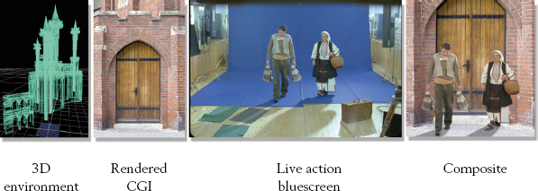
Figure 3-43 Live action composited within a 3D environment
The basic ingredients are illustrated in Figure 3-43. The 3D department has modeled the 3D environment (an elaborate medieval castle in this example), texture mapped it, and added 3D lighting. The CGI is then rendered using a 3D camera that matches the moves of the live action camera. The live action is represented here by the bluescreen plate in Figure 3-43. Finally, the CGI renders and keyed out bluescreen characters are composited together.
There are two different workflows that might be used for this type of shot. The CGI can be rendered by the 3D department so that the compositors get the finished rendered images to composite, or the 3D database describing the castle geometry, texture maps, lights, and camera is given to the compositor to do the rendering himself in the 3D compositing program. If the 3D department does the render and gives the images to the compositor then the live action is effectively being placed over the CGI background as a normal 2D composite and it is not really 3D compositing. If, however, the 3D database is given to the compositor then the live action elements can be placed within the 3D environment like the example in Figure 3-43. This is 3D compositing and is especially effective when the live action must interact with the 3D environment by touching, walking on it, or interactive lighting.
3.8.4 Set Extensions
The introduction of photorealistic CGI made an entirely new visual effect possible, namely set extension. The basic idea is to construct just a very small portion of the required set on the back lot or on a sound stage—just the part where the characters have to walk or interact with the set. A 3D extension of this set is then constructed that exactly matches the edges of the physical set and extended as far as the director needs it to make the shots. For this technique to work the CGI set extension must perfectly match the look and lighting of the live action set. Hence the need for truly photorealistic CGI.
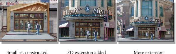
Figure 3-44 A set extension from back lot to big screen
How this works is illustrated in Figure 3-44. The first panel shows the small piece of the actual set built on the back lot, just enough for the characters to walk around. This is then filmed and the film digitized and given to the 3D department to build the 3D set extension. The 3D geometry, texture maps, cameras, and lights are then given to the 2D department which can render the 3D set extensions and composite the live action portion in. In addition to adjusting the lighting and adding other interactive effects between the live set and the 3D extensions, such as shadows and lighting, the compositor can also “adjust” the 3D to compensate for any small alignment errors or drift.
There are several huge advantages to this approach. First, very large, complex, and elaborate set extensions can be built in the computer that would be hopelessly expensive or even utterly impossible in the real world. Second, the 3D set can be blown up, set alight, disintegrated, melted, digested, folded, spindled and mutilated, or treated with any other effect you might imagine, which again would be utterly impossible or hopelessly expensive to do with a real set. Third, the 3D set can be revised, altered, or extended endlessly to satisfy the constantly expanding creative whims of the director. Can you imagine knocking down half of a huge physical set and rebuilding it because the director got an idea for a cool new shot? Or what if the dramatic pullout the director had in mind looked too wimpy, so the set had to be doubled in size? Try that in the real world!
The major modern miracle that makes it possible to put 3D into live action, live action into 3D, set extensions, or any of a long list of other visual effects that combines elements of live action and 3D into the same shot is camera tracking. It is the “glue” that binds the 3D world to the live action world. In order for a 3D object to appear together with a live action element they must both share identical camera moves and lenses. This, it turns out, is a non-trivial problem. I have, in the early days of my visual effects career, tried to match a 3D camera to a live action plate by hand because camera tracking software had not been invented yet. It is a maddening task simply because there are an infinite number of possible combinations of camera location, orientation, and lenses that would appear to match the live action.
None of this is a problem if you have a locked-off shot, of course. You can line up the camera of your 3D object for a good match and then press the render button and go home. Where things go awry quickly is if the camera is moving. While the initial camera lineup may have looked good, as soon as things start to move any erroneous 3D camera movement will cause the 3D objects to drift and squirm in a most disturbing way. The eye, being more sensitive to motion than any other visual stimulant, instantly locks onto the errant objects and spots the fraud.
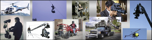
Figure 3-45 A million ways to move a modern camera
But no movie director worth his riding crop will want locked-off visual effects shots. Cameras are no longer limited to the tracks and dollies of yesteryear. Now they ride on great unmanned booms 50 feet into the air, on the front and back of camera cars, they are hand-held, there are steady-cams, gyro-stabilized helicopter cams, cable cams, even a “birdy cam” that rides on a miniature remote control helicopter (check out Figure 3-45). There have never been so many ways to move a camera around to get that truly cool shot. And there has never been a greater need to “reverse engineer” what the live action camera move is so that it can be matched in the 3D part of the picture.
Camera tracking used to be the province of the “match move” department, a special collection of geeks that scurry around late at night working their incantations on ultra-expensive camera tracking software with exotic names like “Boujou,” “Voodoo,” “SynthEyes,” and others. While the match move department is still alive and well, the paradigm shift in compositing is that there are now very capable camera trackers integrated into commercial compositing programs. Not as crafty or powerful as the uber-expensive dedicated programs, but capable of doing a yeoman’s job for most basic shots. Today’s compositor is now a match move artist too. So let us take a look at how camera tracking software actually works.
Camera tracking is actually a two-stage process. The first stage is the actual tracking, where the computer rummages through all the frames in the shot searching for valid “landmarks” in the scene that it can lock onto and follow for a good portion of the shot. These “landmarks” are called tracking targets. The second stage is the “solve,” where the computer grinds on the tracking data it collected to “reverse engineer” the camera’s position, orientation, and lens for each frame of the shot. The digital artist actually assists the computer during both stages, which is where the artist’s experience and talent have a powerful affect on the results.
During the tracking stage the artist can delete tracking points that are confusing the computer and plant some of his own to guide it along. During the solve stage the artist can give the computer any known information about the scene (the size of an object, the distance from the camera to a landmark, the type of lens used, etc.) to help guide the computer towards a successful camera solve. Tragically, in most situations the digital artist will have no information from the scene and must make his best guesses. In spite of this, modern camera tracking software can solve most shots with great accuracy and even provide the type of lens used as well as information about the lens distortion.
3.8.5.1 Tracking the Shot
Here is the first key point about camera tracking—the camera must be moving in order to do camera tracking. It must be moving because the tracking software uses the parallax shift of multiple tracking targets in the picture in order to triangulate the target’s location in 3D space. No camera movement, no parallax. The second key point is that the tracking software only locks onto static objects—the corners of buildings, the landmarks on a mountain—and ignores moving objects like people and cars.
Figure 3-46 depicts a simple scene where a moving live action camera is photographing a coffee table. Note the two black markers on the corners of the coffee table. These are tracking points that the tracker has chosen because they stand out in the scene and move smoothly during the shot. On the right you can see three frames that show how the two tracking markers are moving over the length of the shot. Of course, with a real shot there will be dozens if not hundreds of tracking markers and there will be much more than three frames.
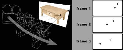
Figure 3-46 A moving camera sees tracking points from different angles
Once the tracking is done we are ready for the camera solve. The computer runs forwards and backwards through the tracking data multiple times using successive refinement to converge on its best solution for the camera data. The camera data has two parts—the camera’s move in 3D space plus the lens characteristics. In addition to the camera data it also generates what is called the “point cloud.” Each of the trackable targets in the scene has been triangulated into 3D space so the computer knows their XYZ coordinates. This collection of 3D points is exported along with the camera data and displayed in the 3D portion of the compositing software (or a 3D program). Figure 3-47 illustrates the point cloud and the “reverse engineered” camera move for all three frames of our imaginary shot.
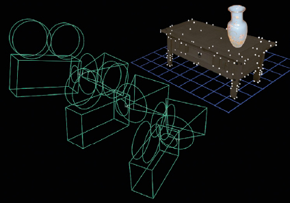
Figure 3-47 The point cloud used to line up 3D objects with the live action
The purpose of the point cloud is to give the digital artist reference points in 3D space to line up the 3D objects. In the case of the coffee table point cloud in Figure 3-47, if we wanted to place a Ming vase on the live action coffee table we would use the point cloud to determine exactly where the table top is, place our vase on it, and then render it with the moving 3D camera that matches the camera move in the live action scene. The vase would then be in the right position and change its viewing angle exactly like it would had it been sitting on the real coffee table. And that is the point—to be able to “copy” a live action camera move into the 3D world and use it to seamlessly add 3D objects to live action scenes.
3.8.6 Small 3D Tasks
We’ve seen how camera tracking and 3D compositing are used to create sophisticated visual effects shots where 3D animation and live action are brought together. But these examples were for large, complex “money” shots. What about the little things? Can camera tracking and 3D compositing be used for the myriad of little problems that compositors have to solve every day? But of course.
There are a thousand little ways the compositor can use his 3D compositing environment to good effect, but we will choose just one typical example to play with. Figure 3-48 shows an ordinary traveling car shot where the camera is simply driving by looking up at the Wells Fargo building. The mission here is to re-dress the building from the evil Wells Fargo big bank monopoly to the evil Starbucks corporate coffee conglomerate. Let’s take a look at the workflow—and keep in mind that this will all be done in the modern 2D compositing department without bothering the match move department or the 3D department.

Figure 3-48 Original building
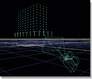
Figure 3-49 Point cloud with camera solve
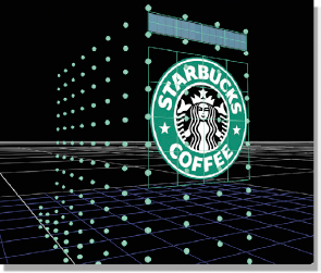
Figure 3-50 Graphics positioned with 3D point cloud

Figure 3-51 Final 3D composite
We start with the original building clip of 100 frames in Figure 3-48 and apply the camera tracking software to produce the point cloud with camera solve shown in Figure 3-49. We now have a matching camera move in the 3D world plus the point cloud that provides “landmarks” in the 3D world that we can use to line up our graphic elements.
Next, we fire up Adobe Photoshop and grab one frame of the clip to crop out the row of windows just below the “Wells Fargo” signage in the original clip. We will lay this row of windows right on top of the Wells Fargo sign to hide it. Somewhere we get a Starbucks logo and prep it in Photoshop with an alpha channel. We now have all of the pieces for our shot.
Referring to Figure 3-50, using the point cloud as a lineup reference we place the row of windows over the Wells Fargo sign and position the Starbucks logo on the side of the building. Some lights and material properties are applied to the logo so it will appear to be in the same light space as the shady side of the building. The cropped windows need no such treatment as they already match perfectly because they are cropped from the original plate. The render then creates 100 frames of the cropped windows and logo perfectly lined up to the original plate. These rendered elements are then composited over the original clip to produce the final 3D composite shown in Figure 3-51.
This entire process would have only taken a couple of hours. One more small detail to attend to, however. The original clip was 35mm film, so we have a noticeable amount of moving film grain which our cropped windows and logo lack. They look “dead” in the shot and will immediately attract attention to themselves as the eye goes to motion first. Both elements will need to be regrained during the composite so their grain structure will match the original plate.
The picture I am trying to paint about 3D compositing is that it is a major paradigm shift for the world of compositing as it represents a massive increase in both the range of compositing effects possible and the technical and artistic requirements placed on the compositor. Not only can 3D compositing be used for large and elaborate set extension shots but it is also very helpful for many of those little things like making clean plates that make up the daily lives of compositors. It also represents a major shift in the entire production pipeline of visual effects as some of the work traditionally done in the 3D department is now being shifted into the 2D department where it can be done faster and cheaper. Compositors that want to future-proof their careers will learn 3D compositing.
*Solid gold man courtesy of Tom Vincze.