
First of all, is it “stereo” or is it “3D?” The movie posters and home TV sets all say “3D,” but the cinematographers, VFX artists, editors, and colorists all call it “stereo.” The terminology is different depending on who you are talking to. If you are talking to someone on the projection or display end of the pipeline (theaters or home TV) they will call it “3D.” If you are talking to someone in production or post-production (cinematography, editing, visual effects, colorists) they will call it “stereo.” Some have even taken to calling it “stereo 3D” or “S3D” just to cover all their bases.
The filmmaking industry is all a-buzz about 3D movies. It represents a major new viewing experience for moviegoers and has the added advantage of actually enhancing the movie experience when properly done. It also gives the theater a competitive advantage over watching Blu-ray HD movies on a home theater system (until there is 3D for the home, anyway). While 3D movies have had at least two incarnations in the past, its “golden era” in the 50s then a “revival” in the 80s, this time 3D movies are here to stay. Here’s why.
Historically (Figure 14-1), 3D movies were notoriously difficult and outrageously expensive to produce and project using 35mm film. Most 35mm cameras were bigger than an old fashion TV set, and a stereo rig with two 35mm cameras was the size of a refrigerator while the monstrous IMAX stereo camera rig is the size of a Volkswagen. There was also the mounting, aligning, and synchronizing of two mechanical cameras, then the beam splitters or mirrors required to get the two cameras closer together than their camera boxes and lenses will permit while losing a full stop of light. The total package weighed more than a female Russian shot-putter could lift.
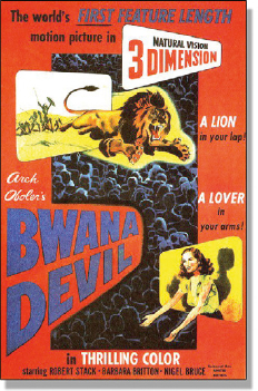
Figure 14-1 Classic 3D movie circa 1952
And that’s just the cameras. Next we have double the film and developing costs (non-trivial expenses) and double the editing hassle and double the dailies projection problems. When the movie goes to a theater there will have to be two prints (left and right eye) at around $2500 each. Then the theater will need two projectors (theater owners HATE to buy equipment) which will have to be synchronized and their lenses and lamps matched. If a print breaks then both prints have to have the same frame cut out so they still match. Sheesh! What a hassle.
Today, however, due to the digitization of the entire movie business the stereo production process is much easier and of higher quality. Even if a movie is shot on 35mm film the first thing that is done is to digitize it. The dailies are digital, the editing is digital, and, of course, the visual effects are all digital. A digital production pipeline results in a much higher-quality movie than an all-film process could ever be.
One of the key developments encouraging stereo movies is that theatrical projection is now going digital. The same projector that displays stereo can also display regular movies. No extra equipment to purchase. No dual prints to purchase for projection. Along with this goes much higher-quality stereo projection technology using polarized light and glasses instead of the funky old red and blue anaglyph glasses of Bwana Devil days. In short, the digital process has made stereo movies practical, high quality, and reasonably economical. That’s why I say they are here to stay this time.
14.2 STEREOGRAPHY
Let us take a moment to understand stereography, the process of creating and projecting a stereo movie. The physical world is 3D. It is the human visual system that perceives it in stereo. The human ability to perceive the depth of a scene in the real world is actually made up from several different visual cues, but the one cue that is used for a stereo movie is “stereopsis”—seeing a scene from two slightly different points of view from two eyes spaced about 2.5 inches apart (the “interpupillary” distance—the distance between the pupils). Figure 14-2 illustrates this principle.
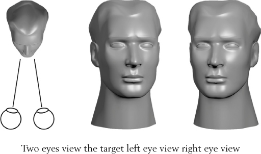
Figure 14-2 Stereopsis—the binocular sense of depth
The two slightly offset eyes produce two slightly different views of the scene which the brain “fuses” together by matching the features between them in a spectacular example of biological image processing. If there is no fusion, there is no stereo perception. If the features don’t match, there will be no fusion. The offset or “disparity” between matched features is the depth cue to the brain. It uses these disparities to sort the various surfaces in the scene into their relative depth positions and voila! You have a stereo image.
Part of the perception of stereo is the convergence of the eyes, which is the angle between the eyes’ line of sight as they lock onto a target. But the human eyes do more than converge on a target. They also focus on that same target. So the eyes have two separate responses to a 3D scene—convergence and focus—which work together when we look at a 3D object in the real world.
The 3D movie projector is always focused on the screen, of course. As objects change depth in the scene the convergence shifts in and out of the screen, but the focus is locked at the screen plane. As a result, a 3D movie is an unnatural act to the brain because the convergence and focus are not locked together like in the real world. This is difficult for some people to do, so they get headaches or eyestrain. Indeed, about 15% of the general population cannot do this trick at all so they cannot see the 3D in a 3D movie.
14.2.1 Stereo Cinematography
While many 3D movies are made with 3D CGI like Shrek (see why we say “stereo” here?), live action stereo movies are photographed with stereo camera rigs. A movie shot with one camera can be converted to stereo in a process called “stereo conversion” which we will look in Section 14.4 Stereo Conversion. A movie can even be made as a “checkerboard” production where some scenes are shot in stereo and others are shot flat then converted to stereo later in post-production. Either way, shooting a movie in stereo is fraught with problems.
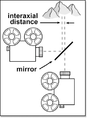
Figure 14-3 Stereo camera rig setup
Recalling that the interpupillary distance between human eyes is about 2.5 inches, for a scene to be filmed with “natural” stereo depth the distance between the centers of the two camera lenses needs also to be about 2.5 inches. When talking about the distance between the camera lenses the interpupillary distance is renamed the interaxial distance. The problem is that camera bodies are much too wide so when put side by side their interaxial distances are much greater than 2.5 inches. This is the reason for all the mirrors and beam splitters. They allow the cameras to be positioned as close together as needed.
Figure 14-3 illustrates a stereo camera rig setup using a half-silvered mirror. The position of the two cameras can be adjusted so that the interaxial distance is anywhere from zero to a foot. Of course, the light level is cut down and polarized reflections are seen by one camera but not the other and if there is the slightest misalignment all is lost. Plus the film must be exactly the same batch and the lenses—don’t get me started about the lenses! Since the lenses must also match perfectly it is very difficult to use zoom lenses with stereo cinematography.
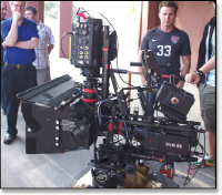
Figure 14-4 A RED camera stereo rig
Of course modern cinematography is moving away from 35mm film towards digital capture with the RED, Viper, Genesis, and other digital cinema cameras. Check out the gnarly dual RED camera stereo rig in Figure 14-4. Digital capture helps the problem—a little. There are still disturbing variations in the light sensors and lenses. The ultimate solution is perfectly integrated stereo digital cinema cameras calibrated at the factory. There are already one or two models available now, with more coming.
While the “correct” interaxial distance is 2.5 inches to mimic human eyes, the stereographer can push this to a degree. The brain knows that the eyes are 2.5 inches apart (European brains know their eyes are 62–65 millimeters apart) so the brain judges the size of objects in a scene based on this known reference. If the interaxial distance is increased too much then the brain says you must be a big head looking at a small object. This is called “hyperstereo,” which shrinks the perceived size of the objects in the picture. Conversely, “hypostereo” is setting the interaxial distance too small, which signals the brain that a small head is looking at a large object thus increasing its perceived size.

Figure 14-5 Stereo camera setups
I heard a great story some years ago about some freshman cinematographer hired to do a stereo shot of the Grand Canyon by helicopter. To “punch up” the stereo effect the hapless DP set the cameras 10 feet apart. The results were disastrous because it made the Grand Canyon look like a kid’s toy. True story.
A critical issue when shooting stereo is how the stereo cameras are aligned with each other as shown in Figure 14-5. The cameras may be converged (“toe in”) on an item of interest or they may be mounted parallel, which means they are essentially converged at infinity. Each of these arrangements has its religious supporters and detractors.
If the cameras are converged then their image planes have a bit of “keystoning” built into them as shown at the top of Figure 14-5. This means that the left and right eye images do not exactly overlap each other and there are regions of the left eye that there is no matching image for the right eye. The amount of keystoning is usually minor so a fix is rarely required, but you should know about it anyway. If the cameras are mounted parallel then the left and right views are shifted horizontally from each other, also shown at the top of Figure 14-5. Each of these problems can be fixed in post but that is another production step, more cost, and slight image degradation. The human brain, of course, has none of these problems as it has superior image processing “wetware.”
For a movie captured in stereo to look right the two cameras must be perfectly aligned with matching lenses and film stock (or image capture chips). While everyone strives for this, a surprising number of things can go wrong. One critical issue when shooting stereo is that there must not be any vertical offset. Both cameras must match at the top and bottom of the scene. Any vertical offset ruins the stereo effect, causes eyestrain, and must be fixed in post (more time, cost, and degradation). It is also essential that the cameras be horizontally parallel (not tilted to each other).
14.2.2 Viewing Stereo
Once you have the left and right eye views the next challenge is how to project the correct view to each eye in such a way that the other eye does not see it. It turns out that this is a non-trivial problem. One of the oldest, cheapest, and poorest-quality methods is “anaglyph”—the old red and blue (cyan, really) glasses (see Figure 14-6). If you have a pair of anaglyph glasses now would be a good time to get them out and try them on the stereo image in Figure 14-7. Anaglyph suffers from a number of deficiencies. Color purity and brightness are reduced, and with high contrast images there will be “ghosting” where one eye’s view “leaks” into the other eye.
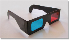
Figure 14-6 Anaglyph glasses

Figure 14-7 Anaglyph stereo image
For theatrical viewing the preferred technology is polarized light and glasses. These are referred to as “passive” glasses because they require no electronics. This is mainly because the audience will need a couple hundred glasses so they need to be inexpensive. The quality is much better than anaglyph, but there is a loss of brightness through the polarized filters.
For a workstation doing stereo visual effects the preferred technology is “active” glasses, which have LCD shutters synced to the monitor. With a high-speed monitor (and a matching high-performance video card) the monitor is actually rapidly alternating (120 times a second) between the left and right views. Since the active glasses are electronic they are expensive, costing well over $100 a pair. This is reasonable for an artist and a client viewing a monitor, but not so reasonable for a theater seating 250.
14.2.3 Stereo Space
Stereo space refers to the apparent location of objects in the 3D scene relative to the screen. Objects may appear (glasses on) to be in screen space (behind the screen, Figure 14-8), at the screen, or in theater space (in front of the screen, Figure 14-9).

Figure 14-8 Image in screen space
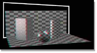
Figure 14-9 Image in theater space
An object’s screen parallax is what determines its apparent location in stereo space. Referring to Figure 14-10 (glasses on) positive parallax positions the object behind the screen like the small head on the left. Zero parallax positions it at the screen level, and negative parallax puts it in front of the screen. (To see a movie of this shot download www.compositingVFX.com/CH14/Figure 14-10.mov)
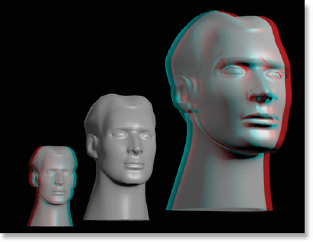
Figure 14-10 The screen parallax
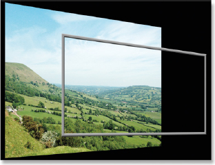
Figure 14-11 The stereo “window”
A core concept in the presentation of a 3D movie is the stereo “window” (Figure 14-11). The idea is that the movie screen in the theater is a “window” through which you are viewing the 3D world outside. This is a very natural perception as our brains have evolved to ignore the edges of windows as we focus on the scene outside. They didn’t really evolve for windows since they are a fairly recent invention. They actually evolved to ignore the tree near our face as we focus on the tiger in the distance, but this handy adaptation works nicely for modern windows too.
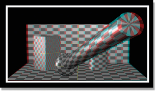
Figure 14-12 Object in screen space
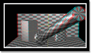
Figure 14-13 Floating window
Most 3D movies are designed to be mostly in screen space, the most natural presentation of the scene. However, there are times when the director wants to thrust something startling in your face so he moves it into theater space by giving it positive parallax. However, there is a danger lurking here.
Consider Figure 14-12 (glasses on), a scene that is mostly in screen space with an object that is thrusting into theater space. It appears perfectly fine with no artifacts. However, in Figure 14-13 the thrusting object suddenly suffers from a stereo display artifact called a “floating window.” The problem is that it has clipped the side of the frame on the right. As a result, the right eye view (blue) is just inside the frame while the left eye view (red) is cropped at the edge. This means that there is missing left eye information so the brain cannot fuse this part of the picture. As a result, this part of the picture appears to be in a ghostly, floating window. To see this more clearly, look at Figure 14-13 one eye at a time, first with the blue eye then the red eye. The red eye is cropped at the frame edge.
14.2.4 Convergence
You will hear a lot about convergence when working with stereo. Convergence is the point in Z where the eyes converge, or intersect, to meet at the same point. Figure 14-14 illustrates how the point of convergences defines the parallax by tracing the left and right lines of sight as red and blue lines. Positive parallax puts the apparent depth of an object behind the screen with the red component of an anaglyph image shifted to the left at the screen. Negative parallax puts it in front with the red component shifted right at the screen. The very important zero parallax positions an object right on the screen with no red/blue “ghosting.” We saw this relationship between the color shifts and their apparent depth earlier in Figure 14-10.
The zero parallax is very important because it defines the screen plane. When looking at an anaglyph image any objects that have no red/blue ghost outline are at zero parallax and are on the screen plane. Shifting the parallax of an object will move that object in and out of the screen. This becomes very important for stereo compositing and stereo conversion as we often need to adjust the parallax of the various objects in the frame to create a good stereo experience for the audience. You will hear the terms “setting the convergence” or making an object “the point of convergence.” This really means to set the object on the screen plane with zero parallax.
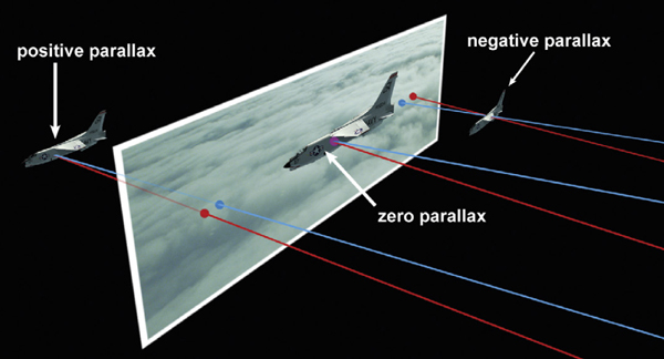
Figure 14-14 Convergence and parallax
The explosion in stereo movies has, of course, created an explosion in stereo compositing since virtually all of the stereo movies are visual effects rich. Not sure what you could do with a stereo romantic comedy. This section focuses on how the stereo theories above apply to creating stereo visual effects. The critical issue for a stereo compositor is to understand the principles of stereography in order to produce shots that will not offend the audience’s eye. Not only do we have to avoid introducing “stereo errors” such as floating windows, but we must also identify and fix stereo problems with the elements that we have been given to composite.
Fixing stereo problems begins with the live action plates. There is a surprisingly long list of things that can go wrong with stereo capture so in the next section we will see what they are and how to fix them. Stereo adds another dimension to compositing greenscreen (and bluescreen) shots so stereo issues involved with keying, painting and rotoscoping are also covered.
14.3.1 Prepping the Stereo Plates
Before beginning any stereo visual effects shot the stereo plates must be prepared. And by prepared, I mean fixed. In Section 14.2.1 Stereo Cinematography, a few of the problems with shooting stereo footage were mentioned. Here we will take a much closer look at those problems and how to fix them. As of this printing the only stereoscopic workflow plug-ins available are Ocula from The Foundry, the makers of Nuke. Where appropriate, the applicable Ocula plug-in will be mentioned.
• Vertical alignment—if one of the two stereo cameras is pointed slightly up or down relative to the other then the vertical alignment between the left and right views will be off. The effect can be seen in Figure 14-15 with the offset marked by the short white lines. Note that vertical alignment can easily be seen with the naked eye without glasses on an anaglyph version of the stereo pair. When viewed with anaglyph glasses the two views become difficult to fuse and look “floaty” and disturbing. Figure 14-16 shows the vertical alignment fixed. Much easier to look at. The obvious fix for vertical alignment may be to simply shift one view vertically, but it may be more complicated than that. The image may actually be off-scale in Y or some other more complicated distortion. Be sure to look at the entire image, not just the rooftops. Use the Ocula plug-in VerticalAligner.

Figure 14-15 Vertical alignment off
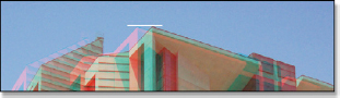
Figure 14-16 Vertical alignment corrected
• Rotational alignment—every effort is made to mount the cameras perfectly parallel to each other so as to not introduce any rotation of one view relative to the other. This is not hard in a side-by-side arrangement, but as we saw earlier the cameras have to be mounted perpendicular to each other. It’s very easy to have a slight error in this type of mounting. While perhaps not noticeable at the center of the picture where everyone is watching, a rotational misalignment gets progressively worse as you move out to the edges. Check out Figure 14-17 with the anaglyph glasses to see how hard the rotational misalignment is on your eyes as you look at the left and right edges.
The obvious fix is to rotate one of the views to correct the rotational misalignment. This was done for Figure 14-18 so you can see how much better the edges of the frame are to the eyes. See if you can figure out how to spot the rotational misalignment clues in the red/blue fringes of the bad anaglyph in Figure 14-17.
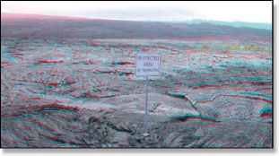
Figure 14-17 Rotational misalignment
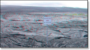
Figure 14-18 Rotation corrected
• Keystoning—we saw earlier in Figure 14-5 that converging or “toeing in” the stereo cameras introduces keystoning into the left and right views. An illustration of this capture problem is shown in Figure 14-19. This can introduce a vaguely disturbing appearance to the stereo pair since the misaligned features will not fuse. Corner pinning can be used to remove keystoning. If not, use the Ocula plug-in VerticalAligner (works for keystoning too).

Figure 14-19 Keystoning from converged cameras
• Color mismatch—the color and exposure of the stereo pairs must obviously be very close without one of them being lighter, darker or off-hue. Unfortunately there is a long list of possible culprits here including slightly different exposures between the two cameras, different responses of the camera light sensors (or film stock), and slightly different amounts of light entering the lenses of the cameras pointed in slightly different directions.
The crude fix is, of course, get out your color grading tools and make them match. However, these color differences can be complex and may require sophisticated image processing tools. Histogram matching can help if the content is suitable, but some shots will require more sophisticated solutions. Use the Ocula plug-in ColourMatcher.
• Polarized reflections—when light reflects off of glass or wet streets or shiny surfaces of any kind it usually becomes partially polarized. When a scene is photographed with two cameras using a beam splitter the beam splitter will pass the polarized light to one camera but block it to the other. As a result, one camera will have hotter reflections and even an overall haze compared with the other. This is a tough one to fix as the polarized reflections will be in some areas of the frame and not others so a single global fix such as color correction or histogram matching will not do the trick. Use the Ocula plug-in ColourMatcher.
• Lens flares—the problem here is that a lens flare is hugely affected by the angle of the lens to the light source. By definition the stereo cameras are capturing light sources at slightly different angles so the lens flares will be different in each view, resulting in the audience’s inability to fuse the flare.
It is extremely difficult to paint or composite one stereo flare to match another. Sometimes the only fix is to remove the flare from both views. If the client absolutely has to have the flare, then replacing it with a similar one might be required. But at least the compositor will now have control over the flare element and can easily make the two views match.
• Lens distortions—while every effort is made to use matched lenses in stereo rigs, they cannot be perfect matches. This will introduce slight differences in the lens distortion of each view, introducing an inconsistency in projection. Zoom lenses are particularly difficult to keep matched.
The “fix” is to shoot camera charts for each lens so a distortion map can be created for correcting the left and right plates individually.
Beyond repairing photographic defects in the captured stereo pair, there can also be changes made for artistic reasons. What happens is that on location the director had a vision of how to shoot the shot, but in post it either did not look as expected or cuts badly with the shots before or after. Either way, changes can be made to the interaxial distance, the convergence, or both.
• Reconvergence—the original stereo pair in Figure 14-20 has a very wide interaxial distance and is converged at the far background. (To view a high resolution version see www.compositingVFX.com/CH14/Figure 14-20.tif) Looking at the image without the anaglyph glasses, the tree in the center far background has no red/blue ghosting so that is the point of convergence. Everything forward of that is pushing into theater space which can be seen with the glasses on. Note also the ghosting on the big tree on the left due to the high contrast of the dark tree against the bright sky as well as the floating window effect.
Figure 14-21 (glasses on) has been reconverged to place the very front of the path at the bottom of the screen so that now everything from there on back goes into screen space (see Figure 14-21.tif). It is also a more comfortable and natural image to look at with no floating window. Remember our stereo window on the world in Figure 14-11?
The reconvergence was done simply by shifting the two views left and right until the red/blue ghosting disappeared from the path. However, notice how it has introduced a problem on the left and right frame edges. The shifted images no longer cover the full frame, which introduces the colored strips on the left and right screen edges. Changing the convergence will require the image to be scaled up a bit to push these artifacts out of frame.
Figure 14-20 Original stereo pair
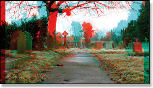
Figure 14-21 Reconverged
• Interaxial distance—as we noticed in Figure 14-20 the interaxial distance was very wide, so we would like to reduce that. This is a non-trivial image processing problem. We can’t just shift the image left or right like with reconvergence. The scene needs to be seen from a slightly different camera angle, shifting the scene parallax of each view as if the cameras were picked up and moved several inches closer together.
What is needed here is a very sophisticated image processing tool. The Ocula plug-in InteraxialShifter can do this. It performs a complex image analysis on the stereo pair, then renders the new views as seen from the new camera locations. When we are done we get the result shown in Figure 14-22, a much reduced interaxial distance (see Figure 14-22.tif). Note that there is far less red/blue ghosting (glasses off) compared with the original in Figure 14-20. Notice also that it is a lot easier to look at (glasses on). Unfortunately this operation can introduce artifacts that will have to be painted out.
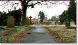
Figure 14-22 Interaxial distance reduced
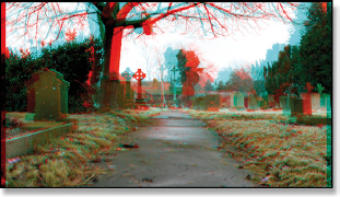
Figure 14-23 Interaxial distance reduced and reconverged
The final example in Figure 14-23 has both the reduced interaxial distance and it has been reconverged (see Figure 14-23.tif). It is now the most pleasant version of all to look at (glasses on). Again we can see that there are artifacts at the left and right edges that will require a zoom to fix. Keep in mind that much can be learned about a stereo pair by looking at the anaglyph version without any glasses.
14.3.2 Compositing Greenscreen Shots
Compositing a stereo greenscreen (or bluescreen) shot is not necessarily twice the work. Assuming that the compositor is using a compositing program set up for stereo work then much of the left/right issues are automatically taken care of. For example, if a blur operation is added the stereo-compliant compositing program will automatically blur both views by the same amount. Not only will a non-stereo-compliant program require two blur nodes, but the compositor must always remember that if the blur is changed for one view the other view must be manually changed to match. Not only is this inefficient production but it also invites mistakes.
There are two big considerations when compositing a stereo job. The first is fine-tuning all of the image processing operations for each view individually. As we saw in Section 14.3.1 Prepping the Stereo Plates above, there is an alarming amount of variability between the supposedly identical left and right views. If one view is slightly out of focus then that view will need a bit less blur than the other. Fortunately, stereo-compliant compositing programs also have provisions for breaking out one of the views for custom treatment.
The other, far more delicate consideration when compositing a stereo job is to avoid introducing stereo errors. Sometimes the live action plates are just shot wrong for the intended visual effect. The stereo compositing artist must be able to spot the unsuitable plates early in the game and fix them before dozens of man-hours are invested in them.
When it comes to keying the greenscreens you can rarely just copy the keyer settings for the other view. As we saw in the prepping plates section above there are several things that can affect the brightness and color of the views, and brightness and color are exactly what keyers key on. You will set up a good key for one view, then check the other view and invariably have to tweak it more than you would like to. If you can balance the color and brightness beforehand with the techniques cited above you will save yourself some keying time. A typical greenscreen stereo pair is shown in Figures 14-24 and 14-25.
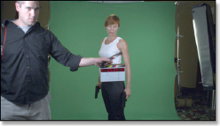
Figure 14-24 Greenscreen left view

Figure 14-25 Greenscreen right view
One other keying problem with stereo shots is sizzling mattes. In a “mono” composite sizzling matte edges are distracting, but not a visual disaster. In a stereo composite the sizzling pixels add a new chattering “Z” component to the composite that is very distracting. A related phenomenon called a masking error is demonstrated below in Section 14.3.2.3 Paint and Roto.
14.3.2.2 Floating Windows
Figure 14-26 shows an anaglyph version (glasses on) of the stereo pair above. (To view a high resolution version see www.compositingVFX.com/CH14/Figure 14-26.tif) The entire scene has positive parallax so it is converged behind the screen and appears comfortably on the other side of the stereo window. However, it has had its convergence fixed. Now check out Figure 14-27, which is how the shot looked right out of the RED camera (see Figure 14-27.tif). The guy on the left is hard to look at because he is now one of those floating windows that we saw in Figure 14-13. His negative parallax places him in front of the screen and he is clipping the edge of the stereo “window frame.”
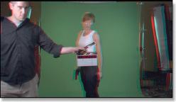
Figure 14-26 Greenscreen anaglyph
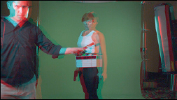
Figure 14-27 Floating window!
The eyestrain is caused by the fact that there are areas of his body that are visible in one view but missing from the other. Take another look at the left and right views in Figure 14-24 and Figure 14-25 and you can see that the right view cuts off much more of his side than the left view. This unshared area is not a problem if the object has positive parallax and lives in screen space because that puts it “outside the window.” which is a natural thing for us binocular humans. However, the same unshared area becomes a major disturbance when the object has negative parallax putting it inside the window. It is now very unnatural and unpleasant to look at. The brain cannot fuse this part of the picture and complains bitterly.
An interesting side note about floating windows is that they are less objectionable at the top and bottom edges of the screen. Even though the negative parallax has thrust it into theater space, because there is no unshared picture content like at the sides of the frame it offends the eye much less. Compare the red/blue ghosting in Figure 14-26 and Figure 14-27 with the convergence and parallax illustration in Figure 14-14. You can see how the positive and negative parallax translates between the illustration and the two pictures.
Compositing greenscreen shots invariably entails some paint and roto work. The big issue here, of course, is now there are twice as many frames to paint and roto as with a standard “mono” job. In addition to that, the paint and roto work must be done much more carefully so it takes yet again more time. It is very easy to introduce stereo errors if the paint or roto does not line up properly. Remember that the brain is fusing the two views so the paint pixels in one view must correlate correctly with the paint pixels in the other view. There are actually two kinds of stereo errors that can be made—one of masking and the other of content. Allow me to illustrate.

Figure 14-28 Original plate
Figure 14-29 A masking error
Figure 14-28 (glasses on) represents a stereo plate that needs to have the Starbucks logo removed from a wall. No problem. We will draw a simple roto shape then cobble in another piece of the wall to cover up the offending logo.
To see an example of a masking error, look closely at Figure 14-29 (glasses on) and you will see a faint “glass ring” floating above the wall where the outside edge of the logo used to be. This artifact was introduced by the left and right roto mask edges being slightly misaligned. The misaligned mask edges cause misaligned picture content in a ring around the replaced logo which cannot be fused causing the visual depth confusion. While the problem is not too offensive in this static image, if the camera were moving it would leap off the screen.
Figure 14-30 A content error
Figure 14-30 shows an error in content, meaning that a slightly different piece of the wall was used for each eye. The brain successfully fuses the mismatched pieces and concludes that this area is at a different depth than the rest of the wall. This is easily seen, even on a static image like this. Note that these problems are not visible to the naked eye (glasses off) on the anaglyph versions.
14.3.3 Compositing CGI
When compositing CGI for a “mono” shot the live action plate has to be camera tracked so the 3D department can render the CGI with a matching camera move—and almost all VFX shots have camera moves these days. For a stereo shot there are obviously two cameras to track—twice the fun. The problem becomes the inevitable small errors in the camera tracking data. For a mono shot the effect would be to cause the CGI character to drift and squirm in the composite, a common problem for which we compositors have many fixes.
For a stereo shot, however, the effect would be much more than drift and squirm. It would also introduce “Z” errors where the character would appear to drift closer and further from the camera. To add to the fun, it is usually ambiguous which of the two views is wrong, making it double tough to fix.

Figure 14-31 Ocean too close to screen
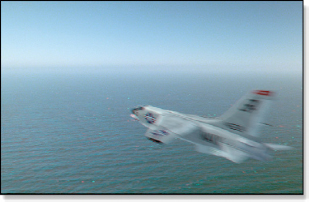
Figure 14-32 Ocean pushed much further back
The same concern for floating windows that was discussed in the greenscreen section above applies to CGI compositing, of course. But there are other issues. Consider Figure 14-31 where a CGI jet has been composited over a live action ocean. The problem with this composite is that the ocean has zero parallax right at the bottom of the screen, which gives the impression that the camera is inches above the water despite the obvious scale of the waves. As a direct consequence, the jet appears to be just a few feet above the water. (To view a high resolution version see www.compositingVFX.com/CH14/Figure 14-31.tif)
In Figure 14-32 the ocean plate has been reconverged to give it a positive parallax at the bottom of the screen pushing it much further back from the camera (see Figure 14-32.tif). Now the jet appears to be a believable few hundred feet above the water. These are exactly the kind of tweaks the compositor will have to make to the live action when compositing CGI in order to end up with a believable composite. And don’t forget to consider the stereo depth of the previous and next shots that cut up against this one.
14.4 STEREO CONVERSION
The current rage for stereo feature films has also ignited a related industry, stereo conversion. In this process a movie that was shot “flat” with one camera is put through an arduous post-production process to turn it into a stereo 3D film. As we will see shortly, this is a very labor-intensive process with much of the labor being in the massive amount of roto work required. As a result, much stereo conversion is being done offshore, largely in India with China not far behind. Even if the conversion is done in the USA, the labor-intensive roto work is usually done offshore.
Many stereo 3D movies are actually produced using the “checkerboard” method where some scenes are shot in stereo and others are converted to stereo in post-production. Each approach, shooting in stereo and converting to stereo, has its advantages and drawbacks so the decision is made scene by scene as to which method to use and they are intercut in the final movie (hence the “checkerboard”). The big advantage of stereo conversion is that it is possible to set the stereo depth and convergence of each shot for best artistic results since its stereo is being constructed from scratch.
Doing a stereo conversion on a feature film is a non-trivial project, and not just from the labor standpoint. There are definite technical issues to address as well as a variety of artistic issues to get right. In this section we will take a close look at the entire stereo conversion process.
14.4.1 The Rubber Sheet Method
While there are several approaches to stereo conversion, the simplest and most pervasive is known as the “rubber sheet” method. Simply put, each object in the scene is isolated with a roto, then the depth in the scene is assigned to each roto, then this information is used to extrude a single polygonal mesh in Z, towards the camera. The original frame is projected onto this extruded mesh, then it is rephotographed with two stereo cameras to create the left and right views.
The most common arrangement is to shoot the left view camera straight on to the extruded mesh so the left view is undistorted and requires no touchup. The right view camera is offset a bit by the interaxial distance to rephotograph the extruded mesh slightly off-angle. Shooting off-angle like this introduces some artifacts which must be repaired as part of the normal part of stereo conversion. What these artifacts are and how they are repaired is covered in later sections. To be sure, some conversion processes shift the two cameras equally left and right so that both views produce artifacts that are half as bad and therefore more easily repaired, but again, there are twice as many to repair. Pick your poison.
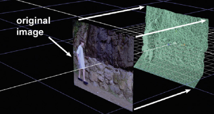
Figure 14-33 Image projected onto an extruded mesh
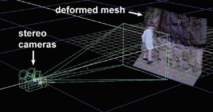
Figure 14-34 Stereo cameras rephotograph the extruded mesh
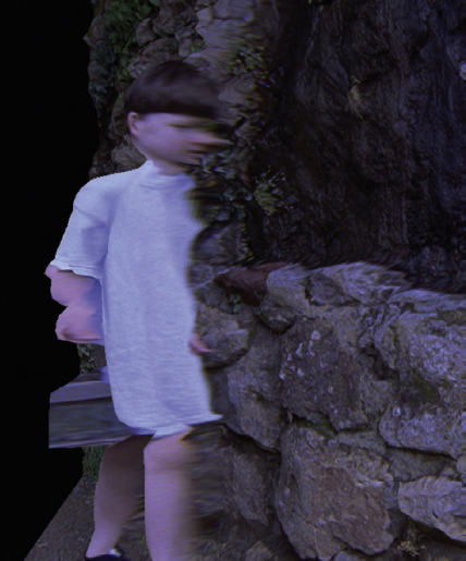
Figure 14-35 Stretched pixels seen off-angle
Figure 14-33 illustrates how the original image is projected onto an extruded mesh. The mesh is extruded by pushing and pulling in Z (towards and away from the camera) to set the depth of the various objects in the scene. Figure 14-34 illustrates how the extruded mesh is then rephotographed with a stereo pair of cameras. (To view a high resolution versions see www.compositingVFX.com/CH14/Figure 14-33.tif and Figure 14-34.tif)
Since the cameras are slightly offset they photograph the same scene from a slightly different angle, which provides the two views for the stereo effect. This trick works because the left camera is square on to the extruded mesh so the image is undistorted. The right camera, however, sees the extrusion slightly off-axis, which also reveals stretching artifacts. An exaggerated off-angle view is shown in Figure 14-35 which clearly shows this dreadful affect. Figure 14-36 shows an anaglyph version (glasses on) of the resulting stereo pair produced by the rubber sheet method. (To see a movie of this shot download www.compositingVFX.com/CH14/Figure 14-36.mov)
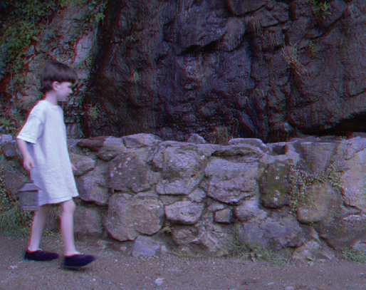
Figure 14-36 Stereo result
The non-rubber sheet methods avoid the artifacts by essentially isolating each object onto its own separate mesh or layer. This mesh is extruded just enough to introduce a pleasing curvature to the surface so the object won’t look like a flat cardboard cutout. The upside of this method is that it produces very high-quality results with far fewer artifacts to repair. The downside is that it is more complicated and therefore more expensive.
14.4.2 Separate Layers
Even with the rubber sheet method objects sometimes need to be placed on their own layer using a separate polygonal mesh. This is done when the rubber sheet method introduces such severe stretching on the projected image that an excessive amount of repair would be required to rework it. The fix is to isolate the object on its own layer. Figure 14-37 shows an example of this arrangement. The isolated object must now have its own matte which is used to turn the mesh surrounding the object invisible in the render.
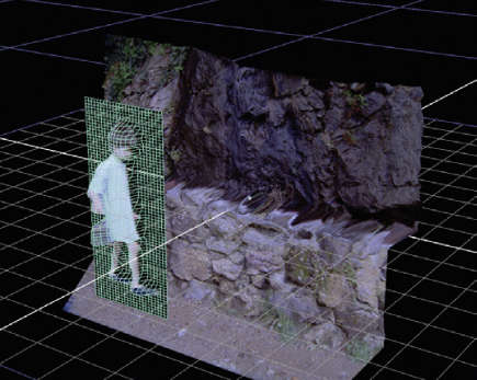
Figure 14-37 An object isolated into its own layer
Some objects need to be placed on separate layers because they are semitransparent such as smoke, dust, fire, or a lens flare. More on the semi-transparent issues in the following section. But the only way to convincingly display a semi-transparent object in a stereo film is to isolate it onto a separate layer and set its depth differently from the background.
14.4.3 The Semi-transparency Problem
There is a common situation in stereo conversion that creates a most vexing problem, and that is semi-transparent objects. A pixel from a semi-transparent object represents two separate objects, each at a different Z depth in the scene. So how can one pixel be at two different depths in the scene? The answer is—it can’t. In order to do it right, this one pixel will have to be separated into two.
The difficulty is that in order to turn the original scene into two separate layers for the composite it must be “de-constructed” into a foreground layer and a background layer for all the semi-transparent regions. To illustrate this we can use the semi-transparent curtains on the left in Figure 14-38 as a case study.
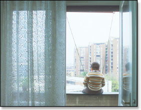
Figure 14-38 The semi-transparency problem
We need a foreground layer that isolates the curtains without the background plus a background layer without the curtains. Also, the curtains need a matte channel that describes their transparency. The problem will be that it is unlikely that there will be any frames available that show the background without the foreground or the foreground without the background so they will both have to be constructed using the same type of compositing techniques used to create clean plates—a non-trivial task.
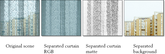
Figure 14-39 Solving the semi-transparency pixel problem
Figure 14-39 illustrates just how vexing the workflow is to separate the foreground from the background for a semi-transparent element. The original scene in the left panel shows the background building through a section of the semi-transparent curtains, showing how they are mixed together in one layer. The next panel shows the separated curtain RGB image and next to that is the separated curtain matte which provides the transparency for the various folds in the curtains. The right panel shows the separated background image without any curtain on it. Again, these layers had to be built from scratch.
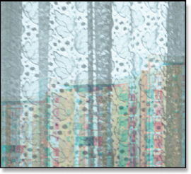
Figure 14-40 Anaglyph version of semi-transparency example
Now that we have all the pieces for our semitransparent example the curtain is assigned a Z depth a few feet from the camera and the background a Z depth a few hundred yards from the camera. When these two elements are rendered with the stereo cameras the curtain and background will shift relative to each other to introduce the stereo depth. An anaglyph version of the result is shown in Figure 14-40 (glasses on). You can see that the buildings look to be in the far distance.
As you can see, semi-transparency is a real problem for the stereo conversion process. It can be difficult and time-consuming to create the separate layers from the original plate. Here are some typical examples of semi-transparency problems:
• Fire
• Dust
• Smoke
• Lens flares
• Objects out of focus
• Motion blurred objects
• Reflections on windows.
14.4.4 Rotoscoping
In order to assign different depths to all of the objects in a scene each object must first be isolated, and that means rotoscoping. Each part of the target has to have a separate roto so that the individual parts can be given their own depth. How the depth is actually assigned will be covered shortly.
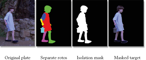
Figure 14-41 Rotoscoping used to isolate objects in the scene
The roto elements are illustrated in Figure 14-41. Starting with the left panel, the original plate, the next panel shows how separate rotos are drawn for each body part. (To see a colorful movie of the separate rotos download www.compositingVFX.com/CH14/Figure 14-41.mov) The next panel shows them combined into a single isolation mask that is used to composite the target if placed on a separate layer. When the isolation mask is applied to the original plate we get the masked target in the right panel ready for compositing.
One critical difference in stereo conversion roto compared with a typical isolation roto used to mask off a target is where the roto spline edge is placed. With an isolation roto the edge is placed 1–2 pixels inside the target. With most stereo conversion processes the roto needs to be 1–2 pixels outside the target. The reason is that it is better to pull a bit of the background forward to the edge of the character than to push the edge of the character back into the background. Often such an artifact will go unnoticed. But if a paint fix is required it is much easier to paint the background than the character.
The roto example in Figure 14-41 was chosen because it was simple and would tell the story well. However, most shots are far more complex requiring much more rotoscoping. A worst-case example can be seen in Figure 14-42. This city shot with all of the baroque building detail and wandering masses of people also has a big camera boom-down so the perspective is changing continuously for the entire shot. This represents a huge rotoscoping task as it would require literally hundreds of rotos per frame for the length of the shot. No wonder most of this roto work is sent offshore where labor costs are lower.
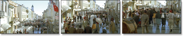
Figure 14-42 An extremely complex roto problem
Most of the movies that are converted to stereo are heavy VFX films. Those visual effects were made from 3D CGI elements that were rendered with an alpha channel in order to be composited over the background plate. Heck, sometimes even the background plate is a CGI element. The point here is that those VFX shots already have “rotos” rendered for the CGI, namely their alpha channels. Logic would dictate that when a VFX heavy film is converted to stereo the VFX studios would provide the alpha channels for the VFX shots to avoid having to hand-draw rotos that already exist. But no, this is often not the case.
I have often asked why this is so, but all I get are shrugs and rolling eyes. No one seems to know. But I do have a theory. Once the VFX of a show are done the jobs are archived and stored away. It can be difficult and time-consuming to dig them out. The VFX studio will not do it for free. The studio will not pay for it. So the stereo conversion studio draws them all over again. One day the process will mature where handing the VFX alpha channels over for the stereo conversion will be the standard operating procedure.
14.4.5 Keying and Painting
As we saw in the section above, rotoscoping is the main method of isolating objects for depth grading. While buildings are easy to rotoscope, cars are more difficult, and people and animals are much more difficult. But there are some things that simply cannot be rotoscoped because their outlines are far too complex and they shift and change too much. Wispy hair blowing in the wind, for example, or water gushing from a broken pipe, or a leafy tree on a windy day. These represent hopeless rotoscoping tasks. So how are we going to create mattes for these elements?
They will have to be keyed out. The problem is that these target objects are not shot on nice bluescreens or greenscreens where they can be conveniently keyed. They are what I call an “uncontrolled” keying problem with the keying targets over random background colors. This situation requires the cleverest of keying techniques to isolate the targets. One common method is a luma-key, which works nicely if you are keying out a black cat against a bright sky, but has trouble in most real-world situations.
If you can’t roto it or key it you might try to paint it. The “wispy hair in the wind” problem cited above would probably be paintable. The problem with paint is that it is just as labor intensive as roto, and it is very difficult to do well. Painted mattes want to chatter and dance about creating a very distracting visual “noise” in the final composite. Basically, paint should be the isolation method of last resort when nothing else will work. There are situations where roto or keying simply will not work, but painting can always be made to work—eventually—given enough time. In worst-case scenarios when a target object is simply impossible to roto, key, or paint, it is removed completely and replaced with a new element, either CGI or live action.
14.4.6 Creating the Depth Map
In Section 14.4.1 The Rubber Sheet Method, I alluded to extruding a polygonal mesh. In this section we will see how this is done using displacement mapping. Displacement mapping is a common CGI technique where the vertices of a polygonal surface are shifted (displaced) based on an image (the map). Brighter parts of the map displace the vertices more, darker parts less. Simply by painting a grayscale displacement map in Photoshop one can create some nice mountainous terrain, for example.
Using this technique for extruding the polygonal mesh, the basic idea is that a “depth map” is created that uses grayscale values to shift the polygonal mesh towards or away from the stereo cameras.
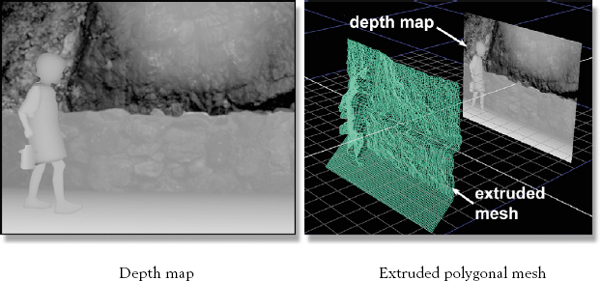
Figure 14-43 Depth map used to deform the polygonal mesh
Figure 14-43 illustrates the technique. The depth map on the left has bright areas that are to come towards the camera and dark areas that are to recede. The panel on the right shows the extruded polygonal mesh resulting from the depth map. This displacement in Z is just enough so that when the texture map is projected onto the polygonal mesh, then photographed from two slightly different angles, it will produce the stereo effect. The big trick is making the depth map.
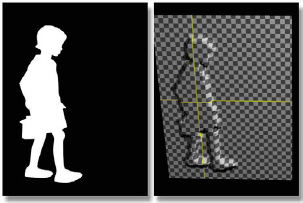
Figure 14-44 Flat depth map
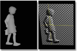
Figure 14-45 Contoured depth map
Not only does each roto have to have its own gray value to determine its Z depth in the scene, but it must also give the surface a rounded or contoured appearance if it is a non-flat object like a person, animal, or tree. Figure 14-44 illustrates what happens if this is not done. The character looks like a flat cardboard cutout because, well, it is. Figure 14-45 shows a more sophisticated approach where each roto is given a variable gray value brighter in the center and darker around the edges to give the resulting extruded mesh a rounded or contoured appearance. Of course, this adds yet another level of complexity to creating the depth map. A simple cheat, the one done here, is to apply a blur to the individual roto pieces imparting a gradient darkening the outer edge. Each roto is then color graded to fit into its place in Z.
In the real world there is no observable stereo effect for objects greater than 100–200 feet from the viewer, but there are religious differences about this maximum stereo difference too. The point here is that there is a maximum distance beyond which the objects do not need to be isolated and given a separate Z depth. They can all be placed on one layer in the scene. Wisdom dictates that this maximum distance be determined for each scene before beginning roto work to avoid doing more work than is needed.
14.4.7 Stereo Paint
Virtually every frame of a stereo conversion will need at least some stereo paint. Since the left eye is normally used as the reference, meaning that the left view camera shoots it straight on, the left view normally looks fine. The right view camera, however, being shifted over to the right, sees the extruded geometry slightly off-angle. This generates two different problems—the edge pixel stretching and revealed background.
As we saw in Figure 14-35, when the image is projected over the extruded polygonal mesh the pixels are stretched in Z on those surfaces that are not perpendicular to the camera. For the left view this is normally not seen. The right view, however, can see them, and they must be fixed by painting them out. Often this is just a few pixels wide and how objectionable it is varies with the scene content. Sometimes the problem is deemed unobjectionable and not fixed. The revealed background, however, is a much bigger issue.
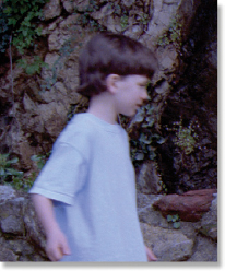
Figure 14-46 Left view
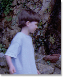
Figure 14-47 Right view shifted left
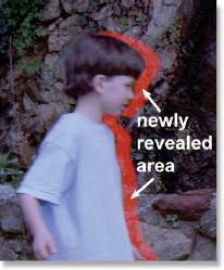
Figure 14-48 Area requiring stereo paint
Consider Figure 14-46, which shows the left camera view of our demo shot. Note the position of the boy relative to the background. The right camera view in Figure 14-47 shows how the boy has shifted to the left. This means that the right camera can now see parts of the background that were covered up in the left view. This newly revealed background must be restored by stereo paint. Figure 14-48 has the area that needs to be restored marked in red.
Sometimes the area to be restored is larger than stereo paint can handle. In that case compositing techniques must be used to lift pieces of the background from nearby frames and lay them in to restore the newly revealed background.
When restoring these background pixels, either by painting or compositing, great care must be taken. It is very easy to introduce small misalignments between the right and left eyes which will destroy the stereo effect because the misaligned pixels will not fuse in the brain. Taking great care means taking a lot of time, so stereo paint is yet another time-consuming labor-intensive aspect to the stereo conversion process.
14.4.8 Clean Plates
A “clean plate” is a standard VFX term that refers to a plate that has had an object in the foreground removed. For example, if you had a photograph of your mom in front of your new car, and you removed your mom from the picture, the remaining car and surrounding background would be the clean plate. Doing this for a single photograph is trivial using Photoshop. Doing this for a clip with 750 moving frames can be very difficult.
Sometimes it is simply better and faster to make a clean plate to replace the entire background, then composite the foreground objects over it rather than trying to paint out all of the artifacts. Figure 14-49 illustrates this approach. First, the foreground object(s) are isolated with a very nice alpha channel, then a clean plate is made for the background. The foreground is placed on its own layer so it can be rephotographed with the offsetting right camera without any revealed background problems or any stretched edge pixel problems. This is a very clean workflow.
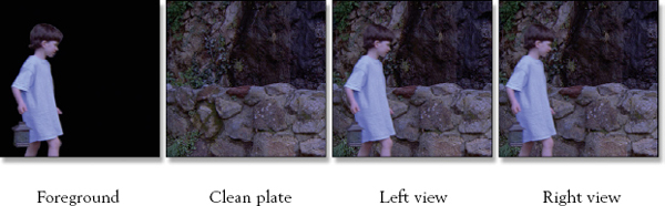
Figure 14-49 Using a clean plate to create left and right views
However, creating a clean plate for a shot is a non-trivial and time-consuming task. It also requires some reasonably skilled visual effects compositors. The roto work and stereo paint can be done by less skilled artists. Creating a clean plate often requires the full range of visual effects techniques such as motion tracking, corner pinning, match move, grain matching, color matching, and so on.
14.4.9 Depth Grading
The final step in the stereo conversion process is the depth grading. This is the process of assigning various objects in the scene their Z depth by setting the grayscale value of the different roto mattes. It gets its name from “color grading” which is a similar artistic process to adjusting the color of a scene, where depth grading is adjusting the depth in a stereo scene. There are a number of technical and artistic issues involved with depth grading. One of the biggest issues is to simply avoid giving the audience eyestrain, migraines, or seizures.
One of the problems with depth grading a movie being converted to stereo (as opposed to one originally shot in stereo) is the pace of editing. A stereo movie does not want fast cuts. The visual adjustment from cut to cut can become annoying to the audience when there are lots of short scenes and frequent cuts. The editing pace must be slower for a stereo movie, but there is no re-cutting the original movie when converting it to stereo. The depth grader is stuck with it. So he must be sensitive to this issue and use creative solutions to minimize it.
14.4.9.1 The Depth Budget
The depth budget is the distance between the minimum and maximum comfortable viewing depths for the audience. This total “depth span” differs from shot to shot depending on the lens used, the interaxial distance, the convergence of the shot, and the size of the movie screen. Yes, a stereo movie seen on IMAX (60 foot screen) will have to be depth graded differently than the version seen on your 52-inch flat panel.
Once the depth budget is set the various objects in the scene can be distributed within it. These are two separate issues. The first, how much depth you have in a scene, is illustrated with the two different depth grades in Figure 14-50 and Figure 14-51. If you have anaglyph glasses, you can see a very large difference in the depth grading for the same scene. Whether a scene should be deep or shallow is largely an artistic choice, but it is also influenced by the previous and next scenes that cut up against it.
The brain takes a moment to gather in a scene immediately after a cut to sort it into its apparent stereo depth. If you cut from a deep scene like Figure 14-50 to a shallow one like Figure 14-51 the transition is hard on your viewers’ eyes. Stereo converted shots must be depth graded to ease the transition between cuts or you risk irritating the audience. In some cases the depth grading might even be subtly changed over the length of a shot to ease the audience into the next shot.

Figure 14-50 A deep depth grade
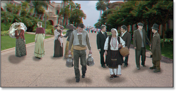
Figure 14-51 A shallow depth grade
A related issue is the depth of the focus object from cut to cut. If a shot has the focus object (the item the director wants the audience to look at) located very near the screen, then in the next shot it snaps back into deep Z, the audience will get a visual whiplash trying to reconverge on it. This is called the “dashboard” effect, named after focusing your eyes on the dashboard of your car, then abruptly switching your view to the road ahead. Your eyes (and brain) will take a moment to make the adjustment. This is not a nice thing to do to your audience.
14.4.9.2 Convergence
Setting the convergence is another critical component of depth grading. Convergence is where the left and right views meet (converge) with no horizontal offset. This places an object exactly on the movie screen, neither in front nor behind it. If you look at an anaglyph image without the glasses a converged object will have no red or blue “ghost” around it because the two views are exactly on top of each other. In Figure 14-52 the scene is converged on the front couple so they appear at the screen plane and everything else is behind them in screen space. (To view a high resolution version see www.compositingVFX.com/CH14/Figure 14-52.tif) Everything except the small bit of ground surface in front of them, of course.
The depth grading has been changed in Figure 14-53 to change the convergence to the four ladies in the background (see Figure 14-53.tif). Since this puts them on the screen plane, the four guys and the front couple have popped forward of the screen and are now in theater space. It also means that the ground plane from the ladies forward is also in theater space, and that’s a problem. We now have a significant floating window.
The situation is even more severe in Figure 14-54 as the convergence point is now the far horizon (see Figure 14-54.tif). This has thrust all of the characters and the ground plane into theater space and the floating window problem is very severe. The floating window is not as objectionable on the background part of the scene (the ground and grass in this example) because the audience’s attention will be focused on the characters (hopefully). Where it will leap off the screen is if one of the characters were to move out of frame crossing the left or right edge. Yikes!

Figure 14-52 Converged on front couple
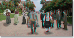
Figure 14-53 Converged on four ladies

Figure 14-54 Converged on the horizon
14.4.9.3 Setting the Depth of Objects
OK, you’ve set your scene depth and established your convergence for the shot, so the last thing to do is to position the various objects in Z space. The key to this step is to estimate where in Z the object is located by inspecting the original flat plate, and then replicate that in the stereo version. It may not be so critical for an object such as a bird flying in the sky as there is no clear visual cues to lock its position in Z. However, with people walking on the ground you darn well better place them at the same Z depth as the ground plane they are walking on. The grayscale value of the depth map directly underneath the character’s feet is sampled then that value is assigned to the character’s feet. The character’s body is then depth graded relative to the feet.
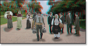
Figure 14-55 Ladies depth graded towards front
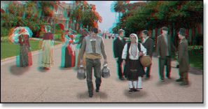
Figure 14-56 Ladies depth graded towards rear
The consequences of failing to accurately “lock” characters to their ground plane is illustrated first in Figure 14-55 where the ladies are graded way too far forward. In fact, they are located at the same Z as the front couple and appear to float. The opposite mistake is illustrated in Figure 14-56 where the ladies have been incorrectly graded too deep into screen space. The odd thing is that their X and Y locations are absolutely correct in both illustrations but they still look like they don’t belong.
Getting objects wrongly positioned in Z has a disturbing effect on the viewer. As you can see in both Figure 14-55 and Figure 14-56 the ladies are in their correct location in X and Y relative to the background plate. They are not too high or off to the side, so they are correctly positioned on the ground plane which provides one important visual cue as to their depth. But their depth grading is wrong, which provides a conflicting visual cue to their depth. It is conflicting visual cues that create stereo errors and disturb the audience. Good depth grading is all about consistent depth cues.